Article

Integration of Methane Reforming and Chemical Looping Technologies for Power Generation from Waste Plastic: Technical and Economic Assessment

1
Chemical Engineering Department, King Fahd University of Petroleum and Minerals, Dhahran 31261, Saudi Arabia
2
Interdisciplinary Research Center for Hydrogen Technologies and Carbon Management (IRC-HTCM), King Fahd University of Petroleum and Minerals, Dhahran 31261, Saudi Arabia
*
Author to whom correspondence should be addressed.
Sustainability 2024, 16(12), 5082; https://doi.org/10.3390/su16125082
Submission received: 25 April 2024 / Revised: 11 June 2024 / Accepted: 12 June 2024 / Published: 14 June 2024
(This article belongs to the Special Issue Progress in Sustainable and Clean Energy Technologies)

Abstract

:
An imperative environmental concern is escalating due to the widespread disposal of plastic waste in oceans and landfills, adversely impacting ecosystems and marine life. In this context, sustainable methods for plastic waste utilisation were evaluated, particularly for power generation. Two case studies were developed to assess the potential utilisation of waste plastic, specifically polyethylene and polypropylene, by integrating gasification with steam methane reforming (SMR) alongside two oxygen-supplying techniques for combustion including cryogenic air separation (ASU) and chemical looping combustion (CLC) for case 1 and case 2, respectively. For this, thorough process simulations of both case studies were performed to obtain detailed material and energy balances. The techno-economic analysis was performed to assess the economic performance of the processes by estimating levelized cost of electricity (LCOE). The results indicated that case 2 is more efficient (5.4%) due to the lower utility requirement of the CLC process as compared to ASU. Consequently, case 2 generated a LCOE of USD 137/MW. It was also seen from the results that the power output is directly proportional to the methane input while the increase in gasifier temperature enhances the H2 and CO content in syngas.

1. Introduction

Polymers and plastics are widely used around the world due to their versatility and cost-effective manufacturing processes. They offer practical qualities such as lower density, chemical resistance, durability, and affordability compared to traditional materials such as wood, metals, and ceramics. Since 1950, plastic production has expanded, and as of the beginning of the twenty-first century, it reached a global total of 200 million tonnes. Due to industrial activity and societal lifestyle preferences, the yearly production of plastic surpassed 400 million tonnes by the end of 2019 [1].
According to a study, the United States currently produces 2 billion tons of municipal solid waste (MSW), and by 2050, it is predicted that the country will produce 3.4 billion tons of plastic garbage annually [2]. Given that the majority of solid and plastic trash is either disposed of in landfills or discharged into the ocean, this has become a global concern. As a result, the environment and marine life have been impacted. Polyethylene and polypropylene make up 29.6% and 18.9%, respectively, of the most commonly used plastic wastes, while the remaining polymers account for 51.5% [2]. Plastic trash incineration has been a popular alternative to landfilling; however, it is extremely damaging to the environment as it releases CO2 and other hazardous gases. Most of these gases are greenhouse gases, which can alter the climate on a global scale.
Unchecked accumulation of non-recycled plastic waste poses significant environmental hazards, and this issue carries substantial implications for the Kingdom of Saudi Arabia (KSA). By 2035, the KSA expects to earn USD 32 billion dollars a year through recycling waste plastic [3]. KSA is putting a strong emphasis on the country’s sustainable development by enacting reuse, recycling, and reconstituting policies regarding waste plastic. To promote sustainable development, the SIRC and SABIC have partnered with the Saudi Arabian government.
To avoid polluting the ecosystem and to provide clean energy for a sustainable future in line with the sustainable development goals provided by United Nations, mitigation of the unchecked disposal of plastic waste is desirable. One key approach in this regard is the circular economy, which includes the recycling and reutilising of waste material. Many recycling methods have been studied and proposed for the recycling of waste plastic. Pyrolysis, for instance, converts plastic waste into valuable fuel, potentially contributing significantly to sustainable growth [4,5]. Quaternary techniques offer a short-term solution for reducing the lifespan of plastic materials. Given that Europe accounts for 19% of the global plastic waste production, which totalled 299 million tonnes in 2013 [3], tertiary recycling is strongly advised. Whilst 26% of the plastic waste in Europe can be recycled through primary or secondary processes, waste plastic can be turned into fuel or syngas for sustainable development, and tertiary recycling may be quite advantageous in this case [6]. In this regard, the thermochemical recycling of waste plastics is the method that is most practical for not only minimizing solid waste disposal but also for producing several significant fuels and chemicals [7,8]. More specifically, gasification processes at a commercial scale can convert waste plastic into syngas which can be thus utilised in chemicals production, biofuels production such as for bioethanol, hydrogen production after RWGS, and electricity production [9,10,11]. Additionally, gasification is a mature technology with lower environmental emissions as compared to combustion [8]. Thus, due to its wide range of application and environmental benefits, gasification was selected as the conversion process in this study.
Recent studies on the subject have mostly been limited to the syngas production, whereas for power generation, additional processing of the syngas is required [12,13]. A combined-cycle power plant (CCPP) plays a crucial role in this scenario, producing energy and electricity through a combination of steam and gas turbines [14]. The combustion of fuel, such as syngas, powers the gas turbine, generating electricity and producing steam that drives the steam turbine, further contributing to electricity production. This system incorporates the Brayton and Rankine cycles to enhance energy recovery, minimize heat losses, and optimize electricity generation [15]. The heat recovery steam generation section (HRSG) is a pivotal component, seamlessly integrating both the steam and gas turbines into a heat recovery system.
To achieve greater efficiency and carbon dioxide removal, CCPPs with chemically looping combustion (CLC) systems show significant promise. In the CLC process, fuel undergoes combustion in the presence of an intermediate agent, often a metal oxide [16,17]. This oxidized fuel and intermediate are cycled between two fluidized bed reactors, with the metal oxide undergoing reduction in a dedicated reactor. Subsequently, the fuel undergoes exothermic oxidation in the designated reactor [18]. The system’s advantage lies in the production of by-products that do not contain diluents, differentiating it from conventional combustion processes.
The primary objective of this study was to develop a feasible model for power generation through waste plastic. For this, two hybrid models were conceptualized including (1) gasification + SMR with air separation unit (ASU) and (2) gasification + SMR with CLC model for power generation as an effort to enhance economic feasibility. To evaluate the proposed models, detailed process simulations were performed on Aspen Plus V11 to obtain the material and energy balance for these processes. When these balances were obtained, a techno-economic analysis was performed to identify the most feasible process. A discounted cash flow model was developed to generate the cash flows of the project and estimate the key economic parameters such as levelized cost of electricity (LCOE) and net present value (NPV). Key technical parameters were identified through these analysis, which were then employed in sensitivity analysis to determine the impact of their variation on power output.

2. Process Simulation and Model Development

2.1. Development of Case Studies

Two different case studies were conceptualized to comprehensively investigate the power generation using waste plastic utilising various oxygen-supplying techniques. The developed case studies included (1) gasification + SMR with ASU and (2) gasification + SMR with CLC. A brief description and the process flow diagrams of each case are detailed below.

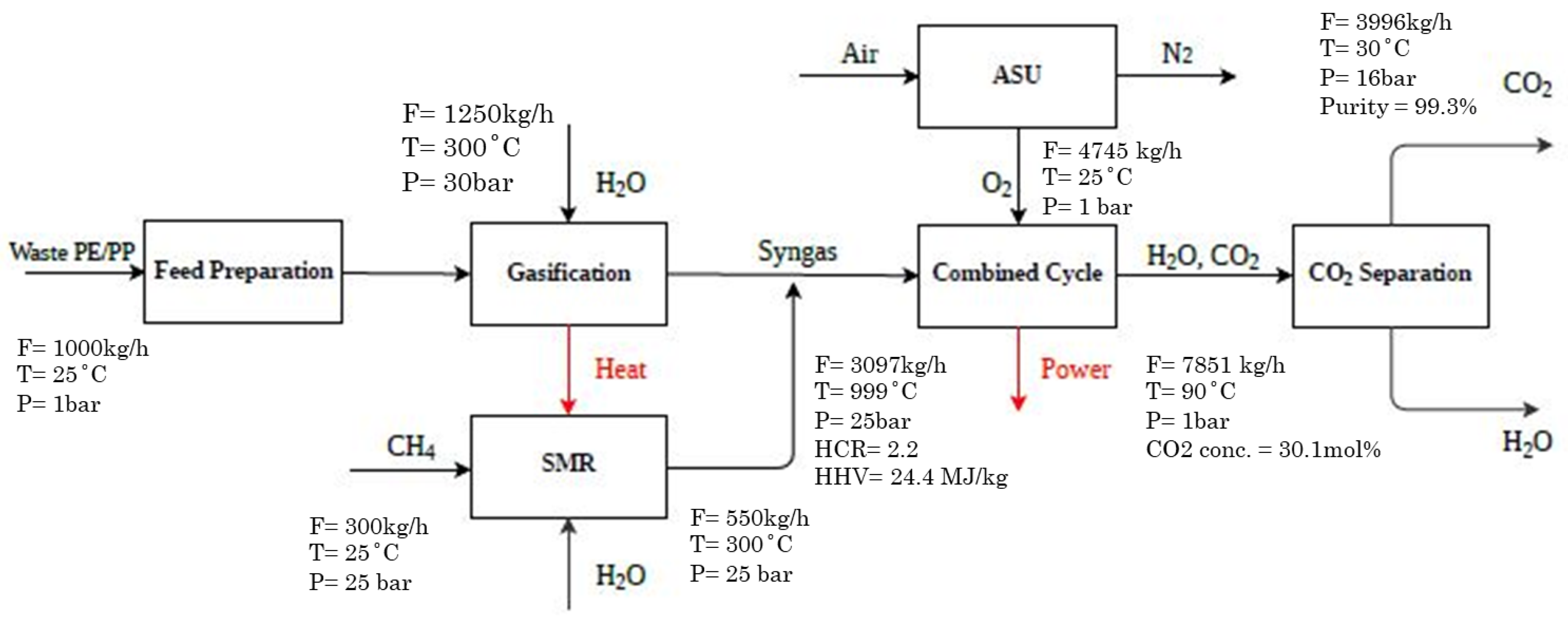
2.1.1. Case 1 (Base Case)

Case 1 consisted of a feed preparation unit, entrained flow gasifier, steam methane reformer, air separation unit, combined cycle, and a carbon purification unit as shown in Figure 1. Before being sent to the gasifier, the feed preparation machine dehumidifies and shreds the plastic feed. The steam gasification unit, operating at 1300 °C and 25 bar, is charged with the prepared plastic feed and gasified by means of steam [19]. The gasifier converts the solid plastic into gaseous components generating syngas and solid residue. The outlet stream at 1300 °C is used to preheat the feed for the SMR to minimize the heating load of the unit. The same amount of waste plastic (1000 kg/h) and natural gas (300 kg/h) were fed into the gasifier and reformers, respectively, to provide equal grounds for comparison. Furthermore, steam-to-plastic (1.25:1) and steam-to-methane (1.83:1) ratios were also kept constant in both cases for the two processes [12].
Once syngas is produced, the combined cycle unit burns syngas using pure oxygen to drive the gas turbine (GT) in order to generate electricity. Pure oxygen is provided to avoid the addition of the carbon capture unit downstream of the power generation process and its energy penalty. For this, ASU is used to separate the oxygen using cryogenic temperatures of −196 °C [20,21]. The outlet flue gases of the GT are still at high temperatures, which are passed through an HRSG to produce superheated steam at 300 °C and 30 bar [22]. The steam generated in the HRSG powers the steam turbine, producing additional power as a result. Carbon dioxide, a byproduct of the process, is eliminated using a straightforward cooling and knock-out drum and subsequently compressed and dehydrated to achieve the selling grade purity of 99.5%.

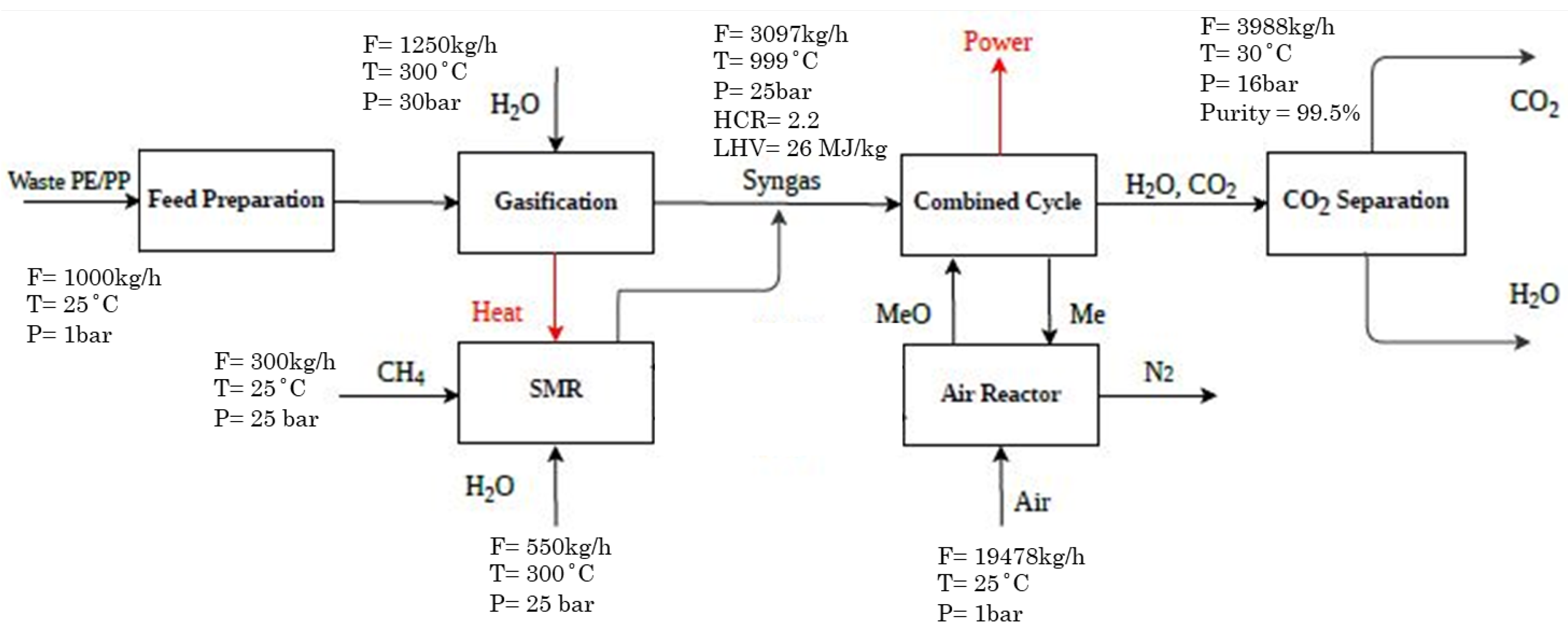
2.1.2. Case 2 (Alternative Case)

In this case, the source of oxygen for the combustion in the gas turbine was changed from ASU to CLC, with the rest of the process kept as it is as shown in Figure 2. CLC is a unique concept which allows the process to be operated with impurities while still providing easy separation and purification of the final product [15,23]. It is based on the inherent reactivity of metal oxides to facilitate the separation of hydrogen from water while avoiding the direct contact of hydrogen with air [24]. This unique process neither requires the upstream nor the downstream CO2 removal, providing economic and environmental savings [24].
In CLC, fuel is burned in the presence of an intermediate agent, typically a metal oxide, which undergoes reduction and oxidation in two fluidized bed reactors [25,26]:
F e 2 O 3 + H 2 F e O + H 2 O
F e 2 O 3 + C O F e O + C O 2
The resulting CO2 is separated from oxygen-rich metal oxide using a cyclone, and the metal oxide is recycled. This process offers advantages over traditional combustion, as byproducts do not contain diluents.

2.2. Development of Simulation Model

To materialize the suggested models, they were simulated using Aspen Plus V11. PP and PE were introduced as the non-conventional components through a definition of their ultimate and proximate analysis, as presented in Table 1 [12]. The Peng–Robinson equation of state model was used to estimate the properties of the involved components and phase equilibrium calculations. RYield was used to simulate the gasification process generating the simple components from the waste plastics. RGibbs was used to model the SMR calculating the products based on the minimization of the Gibbs free energy. To visualize the gas turbine HRSG, a combination of Rstoic, turbine, and HeatX were used for accurate representation.
Based on the material and energy balance obtained from the process simulation, various technical parameters were estimated to yield a comprehensive comparison between the two cases. First the syngas production and its HCR were computed using the following formula:
H C R = M o l e   f l o w   r a t e   o f   h y d r o g e n   i n   s y n g a s M o l e   f l o w   r a t e   o f   c a r b o n   m o n o x i d e   i n   s y n g a s
Secondly, a more important parameter providing a wholistic view of the two process was calculated, i.e., process efficiency, through the following formula:
ɳ = E l e c t r i c i t y   p r o d u c e d L H V P P + L H V P E + L H V N G + U t i l i t i e s   c o n s u m e d × 100
where PP is polypropylene, PE is polyethylene, and NG is natural gas.

2.3. Techno-Economic Analysis

An economic analysis of the two cases was performed to analyse their feasibility in the current market. The economic analysis consisted of capital and manufacturing costs. The assumptions used in the analysis are summarised in Table 2.
Installed costs of general equipment were calculated through Aspen plus cost analyser, whereas the specialised equipment, such as reactors, was scaled with the help of previous studies [27,28] using the following formula [29,30]:
I n s t a l l e d   C o s t = ( N e w   C a p a c i t y R e f e r e n c e   C a p a c i t y ) n × R e f e r e n c e   i n s t a l l e d   C o s t × ( C E P C I 2023 C E P C I R e f )
where n is the scaling factor. These installed costs were then used to calculate the total CAPEX using multiple factors as summarised in Table 3.
The OPEX was computed based on the raw material (CRM), utility (CUT), wastewater treatment (CWT), labour (COL), and other direct operating expenses including maintenance (2% of FCI) and laboratories charges (10% of COL). The formula for OPEX is as follows:
O P E X = 0.28 F C I + 2.73 C O L + 1.23 ( C U T + C W T + C R M )
The net present value (NPV) and the rate of return on investment were estimated as follows [29]:
N P V = n = 0 20 ( C a s h   F l o w ) n ( 1 + r ) n
where r is the discount rate, and n is the project life. The calculation of MSP involves an iterative process where the electricity price is adjusted until the project’s NPV reaches equilibrium at zero. Finally, the calculation of LCOE was performed to compare the proposed process with the conventional power generation process. The equation used for LCOE is as follows:
L C O E = N P V   o f   t o t a l   c o s t   o v e r   l i f e   t i m e N P V   o f   e l e c t r i c a l   e n e r g y   p r o d u c e d   o v e r   l i f e   t i m e

3. Results

3.1. Technical Analysis with Stream Compositions

Detailed material and energy balances of both cases were obtained from the simulations performed on Aspen Plus, as shown in Table 4. With the same input flows as described in Section 2.1.1, the gasifier generated a constant 2250 kg/h of syngas, with an HCR of 1.86. Both cases implementing the same reforming technique produced the same amount of syngas, i.e., 850 kg/h, with an HCR of 3.5.
When combined with the syngas produced from the gasifier, the HCR for both cases were reduced to 2.2 due to the lower HCR of the gasifier outlet stream. The combined syngas was burnt in the presence of 5 mol% excess oxygen in the combustion chamber of gas turbine to achieve complete combustion. The combustion produced 7633 kg/h of flue gas at 1500 °C and 1454 °C, respectively. The difference in the temperature of the flue gas resulted in slightly different power outputs for the two cases, as shown in Table 5. Finally, the cooled flue gas from the HRSG was separated in the knockout drum to generate 3996 kg/h of CO2 with a purity of 99.5 mol%.

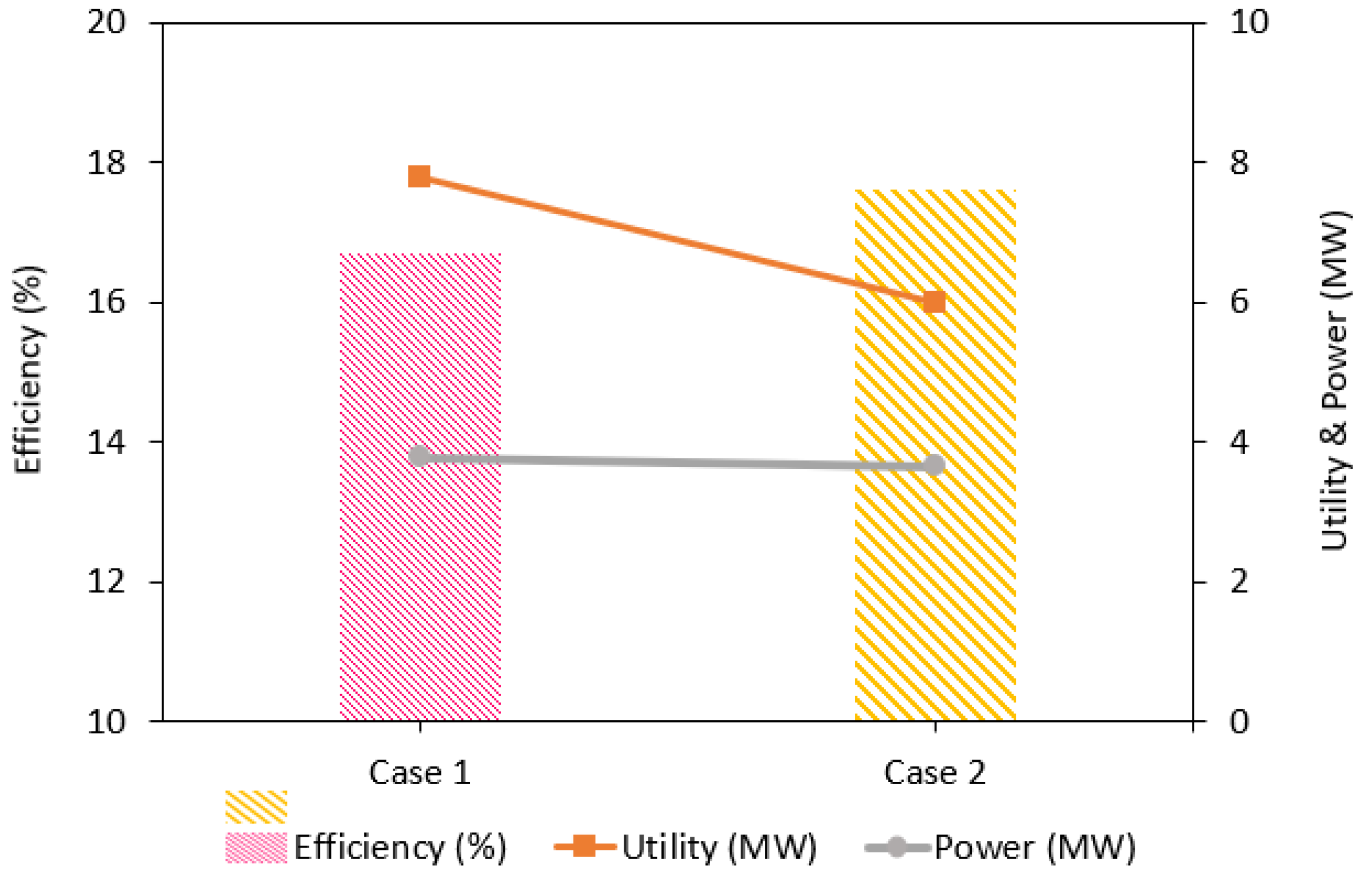
3.2. Process Performance Analysis

Key performance parameters were estimated through process simulation and technical analysis, as presented in Table 5. As the cases utilised same syngas production techniques and input flows, the syngas and its HCR were equal in both cases. The divergence lay in the combustion process, as although both cases utilised a 5 mol% of excess oxygen for combustion, the flue gases produced emerged at different temperatures. In case 1, which utilised oxygen through ASU, an outlet stream of 1500 °C was generated, whereas in case 2, the temperature was slightly lower at 1454 °C. The probable reason for this difference lies in the inclusion of metal in the CLC which absorbs some heat of combustion during the process.
Additionally, the utility requirement of the two processes varied due to the difference in the way oxygen was supplied for the combustion. ASU, being the energy intensive process, resulted in higher utility requirement of 7.8 MW. On the other hand, case 2, utilising CLC, required 23.1% less utility for its operation, as shown in Figure 3. As a result of the combination of these factors, although case 1 generated 3.4% more electricity, case 2 exhibited a 5.4% higher efficiency.

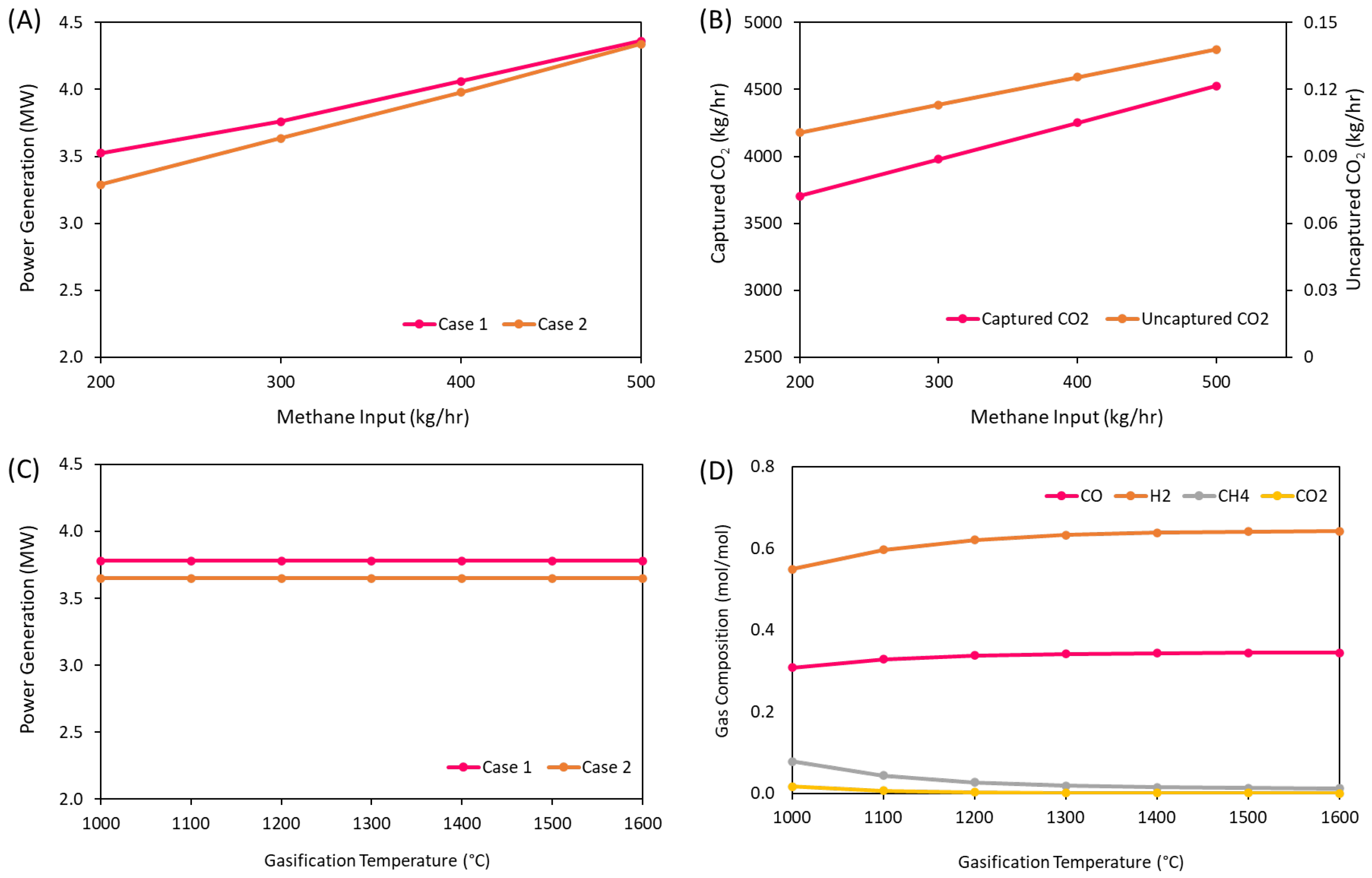
3.3. Impact of Operational Conditions on Process Performance

Initially, a sensitivity analysis of the power output against the methane input was performed. Figure 4 shows a linear increase in power production with the increase in the CH4 input in SMR for both scenarios. The linear trend gives us the indication that the process efficiency and economic would remain same with the increase in capacity. However, the graph shows that case 2 has a steeper trend. It starts with a lower power generation output but matches the capacity of the case 1 at 500 kg/h methane input. This indicates that the efficiency difference between the two scenarios will keep on increasing with the increase in the methane input.
Secondly, the effect of the gasifier temperature on the syngas composition was evaluated. The graph shows an exponential increase in H2 and CO (desired) components in the syngas exiting from gasifier until approximately 1300 °C and vice versa for the CH4 and CO2. After 1300 °C, the trend becomes steady, which emphasize that the further increase in the gasifier temperature does not help in increasing the desired components.
After that, impact on power generation can be observed with the variation in gasifier operating temperature. The graph shows no variation in the overall power production with the increase in the gasifier’s temperature. This is due to the fact that although the increase in temperature converts the CH4 produced during the gasification into H2 and CO, the overall combustible components remain the same, and in turn, the power produced due to the combustion remains the same. However, it is important to note that the form of combustibles (either H2 or CH4) does not affect the material and energy balance, but it is important for the designing phase where the pipelines, equipment, burners, etc., are specifically designed for a certain component. Inclusion of a component for which the equipment is not designed will result in operational problems and hazards.

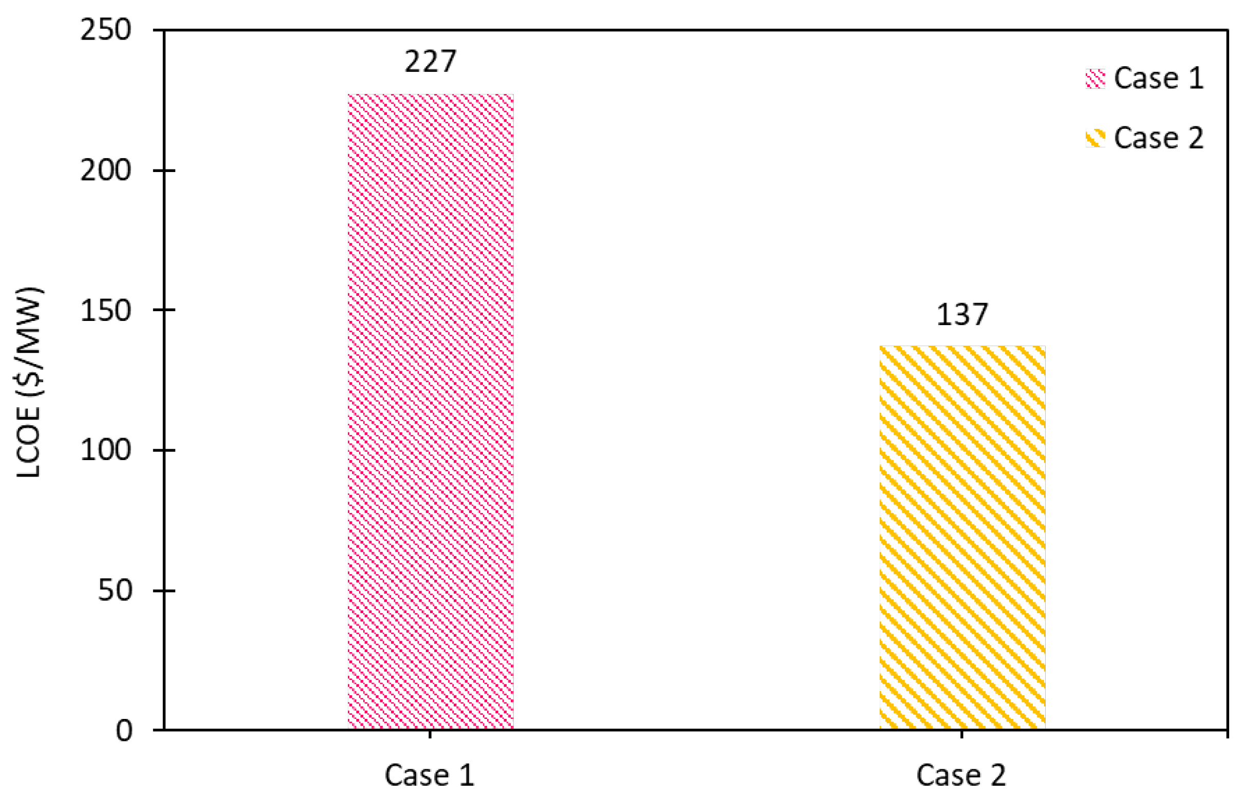
3.4. Economic Analysis

The economic analysis of the studied cases was performed to assess the economic viability of the power generation processes in the current market. First, the CAPEX and OPEX for both cases were calculated, as shown in Table 6. Notably, the calculation shows a significant difference between the CAPEX of the developed cases. However, the OPEXs of both the cases were quite consistent with each other. The observed difference in the CAPEX is primarily due to the higher capital investment required for the ASU, whereas the CLC is relatively cheaper in construction. On the other hand, although case 2 requires fewer overall utilities as compared to case 1, the cost of utilities is slightly higher for the same case. This is due to the fact that the case 2 has a higher contribution of heating utility, which typically incurs higher expenses than does the cooling utility. As a result, the overall cost for case 2 slightly exceeds that of case 1.
A cost breakdown of CAPEX and OPEX of the developed cases is shown in Figure 5. Figure 5A shows the constituents of the CAPEX contributing to the total value, with equipment installation costs emerging as the primary contributor at 52.3% for both cases. On the other hand, the utilisation of waste plastic as a raw material minimises the raw material cost as compared to other constituents of the OPEX. Therefore, it makes the utility costs as the main economic driver in the OPEX, followed by the labour cost.
Base on the economic cashflows, LCOE was calculated for the two scenarios, providing a good parameter for direct comparison with the current electricity prices as shown in Figure 6. Due to a significant difference in the CAPEX of the cases, LCOE for the case 1 was significantly higher than rest of the cases, yielding an absolute value of USD 227/MW, whereas the case 4 (USD 131/MW) proved to be most economical among the competitors.
To rate and compare various wastes and their respective recycling processes for specifically power generation purposes, the literature was consulted. The LCOE for various cases is summarized in Table 7. At the first glance, it can be concluded that the recycling of waste is not a cheap process, specifically for power generation. Only one out of five processes yielded a LCOE below USD 100/MW. Process 1 resulted in exceptionally high cost because it employed fuel cell from gasified waste instead of CCPP. Apart from waste type and recycling process, waste utilisation also depends upon the supply chain and handling of the waste, which can improve the economics if done properly. As seen from the data, two MSW processing studies employing anaerobic digestion resulted in significantly different results. Furthermore, anaerobic digestion using landfill gas has a limited life span with varying landfill gas production which effects its performance. Lastly, the comparison shows that the LCOE of the present study employing gasification had the second lowest value, which indicates that it warrants further exploration and that it is feasible for power generation.

4. Conclusions

The study conducted a comprehensive evaluation of the power generation potential derived from waste plastic, employing gasification and methane reforming techniques. This research sheds light on the efficacy of waste plastic utilisation for power generation, providing valuable insights into key process parameters, LCOE and CO2 savings. The two developed case studies differed in their oxygen-supplying techniques due to which the power output and the process efficiency varied. Techno-economic analysis showed that the case 1, utilising ASU, required 23.1% more utilities, thereby resulting in 5.4% lower efficiency despite its higher power output. Consequently, case 2 generated a lower LCOE of USD 137/MW, whereas both cases effectively mitigated CO2 emissions by avoiding almost 3996 kg/h of CO2. Additionally, sensitivity analysis highlighted a direct relationship between power output and methane input, while an increase in gasifier temperature enhanced the H2 and CO content in syngas. Interestingly, gasifier temperature exhibited a flat response on power output due to the same level of combustibles, indicating no significance for the power generation process. Lastly, the comparison of LCOE with the previous studies showed that the current process is more compatible and shows the potential of sustainable power generation. However, it is essential to conduct more research to further improve the design to optimize the LCOE. Furthermore, government and industrial support is required for performing scale-up studies and practical demonstration.

Author Contributions

Conceptualization, F.A. and U.A.; methodology, F.A. and U.A.; software, F.A. and U.A.; validation, F.A.; formal analysis, F.A.; investigation, F.A. and U.A.; resources, F.A. and U.A.; data curation, F.A.; writing—original draft preparation, F.A.; writing—review and editing, F.A.; visualization, F.A.; supervision, U.A.; project administration, U.A. All authors have read and agreed to the published version of the manuscript.

Funding

The authors would like to acknowledge the support provided by the Deanship of Research Oversight and Coordination (DROC) and Interdisciplinary Research Center for Hydrogen Technologies and Carbon Management (IRC-HTCM) at King Fahd University of Petroleum & Minerals (KFUPM) for funding this work through project no. INHT2418.

Institutional Review Board Statement

Not applicable.

Informed Consent Statement

Not applicable.

Data Availability Statement

Data are contained within the article.

Conflicts of Interest

The authors declare no conflicts of interest.

References

  1. Ritchie, H.; Roser, M. Plastic Pollution. 2018. Available online: https://ourworldindata.org/plastic-pollution#citation (accessed on 24 April 2024).
  2. Almohamadi, H.; Alamoudi, M.; Ahmed, U.; Shamsuddin, R.; Smith, K. Producing hydrocarbon fuel from the plastic waste: Techno-economic analysis. Korean J. Chem. Eng. 2021, 38, 2208–2216. [Google Scholar] [CrossRef]
  3. Ahmed, U.; Zahid, U.; Jeong, Y.S.; Lee, C.-J.; Han, C. IGCC process intensification for simultaneous power generation and CO2 capture. Chem. Eng. Process. Process Intensif. 2016, 101, 72–86. [Google Scholar] [CrossRef]
  4. Shah, H.H.; Amin, M.; Iqbal, A.; Nadeem, I.; Kalin, M.; Soomar, A.M.; Galal, A.M. A review on gasification and pyrolysis of waste plastics. Front. Chem. 2023, 10, 960894. [Google Scholar] [CrossRef]
  5. Zhang, Y.; Ji, G.; Ma, D.; Chen, C.; Wang, Y.; Wang, W.; Li, A. Exergy and energy analysis of pyrolysis of plastic wastes in rotary kiln with heat carrier. Process Saf. Environ. Prot. 2020, 142, 203–211. [Google Scholar] [CrossRef]
  6. Erkiaga, A.; Lopez, G.; Barbarias, I.; Artetxe, M.; Amutio, M.; Bilbao, J.; Olazar, M. HDPE pyrolysis-steam reforming in a tandem spouted bed-fixed bed reactor for H2 production. J. Anal. Appl. Pyrolysis 2015, 116, 34–41. [Google Scholar] [CrossRef]
  7. Santos, S.M.; Assis, A.C.; Gomes, L.; Nobre, C.; Brito, P. Waste Gasification Technologies: A Brief Overview. Waste 2022, 1, 140–165. [Google Scholar] [CrossRef]
  8. Arena, U. Process and technological aspects of municipal solid waste gasification A review. Waste Manag. 2012, 32, 625–639. [Google Scholar] [CrossRef]
  9. Midilli, A.; Kucuk, H.; Topal, M.E.; Akbulut, U.; Dincer, I. A comprehensive review on hydrogen production from coal gasification: Challenges and Opportunities. Int. J. Hydrogen Energy 2021, 46, 25385–25412. [Google Scholar] [CrossRef]
  10. Saebea, D.; Ruengrit, P.; Arpornwichanop, A.; Patcharavorachot, Y. Gasification of plastic waste for synthesis gas production. Energy Rep. 2020, 6, 202–207. [Google Scholar] [CrossRef]
  11. Rizwan, M.; Saif, Y.; Almansoori, A.; Elkamel, A. Optimal processing route for the utilization and conversion of municipal solid waste into energy and valuable products. J. Clean. Prod. 2018, 174, 857–867. [Google Scholar] [CrossRef]
  12. Al-Qadri, A.A.; Ahmed, U.; Jameel, A.G.A.; Zahid, U.; Usman, M.; Ahmad, N. Simulation and Modelling of Hydrogen Production from Waste Plastics: Technoeconomic Analysis. Polymers 2022, 14, 2056. [Google Scholar] [CrossRef]
  13. Williams, J.M.; Bourtsalas, A.C. Assessment of Co-Gasification Methods for Hydrogen Production from Biomass and Plastic Wastes. Energies 2023, 16, 7548. [Google Scholar] [CrossRef]
  14. Xu, H.; Shi, B. Design and System Evaluation of Mixed Waste Plastic Gasification Process Based on Integrated Gasification Combined Cycle System. Processes 2022, 10, 499. [Google Scholar] [CrossRef]
  15. Consonni, S.; Lozza, G.; Pelliccia, G.; Rossini, S.; Saviano, F. Chemical-Looping Combustion for Combined Cycles With CO2 Capture. J. Eng. Gas Turbine Power 2006, 128, 525–534. [Google Scholar] [CrossRef]
  16. Joshi, A.; Shah, V.; Mohapatra, P.; Kumar, S.; Joshi, R.K.; Kathe, M.; Qin, L.; Tong, A.; Fan, L.S. Chemical looping-A perspective on the next-gen technology for efficient fossil fuel utilization. Adv. Appl. Energy 2021, 3, 100044. [Google Scholar] [CrossRef]
  17. Di Giuliano, A.; Capone, S.; Anatone, M.; Gallucci, K. Chemical Looping Combustion and Gasification: A Review and a Focus on European Research Projects. Ind. Eng. Chem. Res. 2022, 61, 14403–14432. [Google Scholar] [CrossRef]
  18. Ghosh, S.K. Energy Recovery Processes from Wastes, 1st ed.; Springer: Singapore, 2020. [Google Scholar] [CrossRef]
  19. Al-Qadri, A.A.; Ahmed, U.; Jameel, A.G.A.; Ahmad, N.; Zahid, U.; Zein, S.H.; Naqvi, S.R. Process design and techno-economic analysis of dual hydrogen and methanol production from plastics using energy integrated system. Int. J. Hydrogen Energy 2023, 48, 10797–10811. [Google Scholar] [CrossRef]
  20. The Linde Group, Air Separation Plants. 2018. Available online: https://www.linde-engineering.com/products-and-services/process-plants/air-separation-plants (accessed on 24 April 2024).
  21. Khan, A.; Abbas, A.; Dickson, R. Towards a low-carbon future: Exploring green urea synthesis for sustainable agriculture. Green Chem. 2024, 26, 1551–1565. [Google Scholar] [CrossRef]
  22. Montiel-Bohórquez, N.D.; Agudelo, A.F.; Pérez, J.F. Modelling of an Integrated Plasma Gasification Combined Cycle power plant using Aspen Plus. J. King Saud Univ. Eng. Sci. 2022, in press. [Google Scholar] [CrossRef]
  23. Bahzad, H.; Shah, N.; Mac Dowell, N.; Boot-Handford, M.; Soltani, S.M.; Ho, M.; Fennell, P.S. Development and techno-economic analyses of a novel hydrogen production process via chemical looping. Int. J. Hydrogen Energy 2019, 44, 21251–21263. [Google Scholar] [CrossRef]
  24. Kong, F.; Swift, J.; Zhang, Q.; Fan, L.-S.; Tong, A. Biogas to H2 conversion with CO2 capture using chemical looping technology: Process simulation and comparison to conventional reforming processes. Fuel 2020, 279, 118479. [Google Scholar] [CrossRef]
  25. Czakiert, T.; Krzywanski, J.; Zylka, A.; Nowak, W. Chemical Looping Combustion: A Brief Overview. Energies 2022, 15, 1563. [Google Scholar] [CrossRef]
  26. Qing, M.; Jin, B.; Ma, J.; Zou, X.; Wang, X.; Zheng, C.; Zhao, H. Thermodynamic and economic performance of oxy-combustion power plants integrating chemical looping air separation. Energy 2020, 206, 118136. [Google Scholar] [CrossRef]
  27. Wu, W.; Xu, H.; Shi, B.; Kuo, P.-C. Techno-economic analysis of plastic wastes-based polygeneration processes. Chem. Eng. Process. Process Intensif. 2023, 184, 109297. [Google Scholar] [CrossRef]
  28. Farajollahi, H.; Hossainpour, S. Macroscopic model-based design and techno-economic assessment of a 300 MWth in-situ gasification chemical looping combustion plant for power generation and CO2 capture. Fuel Process. Technol. 2022, 231, 107244. [Google Scholar] [CrossRef]
  29. Turton, R.; Bailie, R.C.; Whiting, W.B.; Shaeiwitz, J.A. Analysis, Synthesis and Design of Chemical Processes, 3rd ed.; Prentice Hall: Upper Saddle River, NJ, USA, 2013. [Google Scholar] [CrossRef]
  30. Khan, M.A.; Abbas, A.; Dickson, R. A strategy for commercialization of macroalga biorefineries. Renew. Sustain. Energy Rev. 2023, 187, 113703. [Google Scholar] [CrossRef]
  31. van der Roest, E.; van der Spek, M.; Ramirez, A.; van der Zwaan, B.; Rothenberg, G. Converting Waste Toilet Paper into Electricity: A First-Stage Technoeconomic Feasibility Study. Energy Technol. 2017, 5, 2189–2197. [Google Scholar] [CrossRef]
  32. U.S. Department of Energy. Waste-to-Energy from Municipal Solid Wastes. 2019. Available online: www.energy.gov/eere/bioenergy (accessed on 1 June 2024).
  33. Pheakdey, D.V.; Van Quan, N.; Xuan, T.D. Economic and Environmental Benefits of Energy Recovery from Municipal Solid Waste in Phnom Penh Municipality, Cambodia. Energies 2023, 16, 3234. [Google Scholar] [CrossRef]
  34. Nubi, O.; Morse, S.; Murphy, R.J. Prospective Life Cycle Costing of Electricity Generation from Municipal Solid Waste in Nigeria. Sustainability 2022, 14, 13293. [Google Scholar] [CrossRef]
Figure 1. Block flow diagram of power generation from waste plastic utilising steam methane reforming (SMR) and air separation unit (ASU).
Sustainability 16 05082 g001
Figure 2. Block flow diagram of power generation from waste plastic utilising steam methane reforming (SMR) and chemical looping (CLC).
Sustainability 16 05082 g002
Figure 3. Correlation of the utility requirement and power generation of process efficiency for the developed scenarios.
Sustainability 16 05082 g003
Figure 4. Sensitivity analysis of (A) power generation and (B) captured and uncaptured CO2 against methane input, (C) power generation, and (D) captured and uncaptured CO2 against gasification temperature.
Sustainability 16 05082 g004
Figure 5. Breakdown of (A) capital expenditures (CAPEX) and (B) operating expenditures (OPEX).
Sustainability 16 05082 g005
Figure 6. Levelized cost of electricity (LCOE) for the developed cases.
Sustainability 16 05082 g006
Table 1. Ultimate and proximate analysis of polyethylene and polypropylene used in the study [12].
ComponentsPolyethylenePolypropylene
Ultimate analysis (wt%)
Moisture content0.020
Ash content0.150.70
Volatile matter99.8399.30
Proximate analysis (wt%)
Carbon content85.8186.23
Hydrogen content13.8612.28
Nitrogen content0.120.62
Sulphur content0.060.17
Ash content0.150.70
LHV (Lower heating value) MJ/kg38.0444.70
Table 2. Assumed parameters for the economic analysis.
Assumed ParametersValue
Costing year2023
Plant operational life20 years
Construction period2 years
Operating hours/year8000
Depreciation of general plant7 years
Discount rate 8% per year
Tax rate15% per year
Table 3. Factors used for calculation of total capital investment. ISBL—inside battery limit.
Economic FactorsValues
Total direct cost (TDC)
Warehouse4% of ISBL
Site development9% of ISBL
Additional piping4.5% of ISBL
Total indirect cost (TIDC)
Field expenses10% of TDC
Prorateable costs10% of TDC
Project contingency10% of TDC
Home office and construction10% of TDC
Other costs10% of TDC
Capital expenditures (CAPEX)
Working capital (WC)5% of FCI
Fixed capital investment (FCI)TDC + TIDC
Land6% of (Installed costs)
Table 4. Operating parameters and stream compositions at the exit of each unit.
Plastic
Feed
Steam to
Gasifier
Gasifier OutletMethane to SMRReformer OutletGT Outlet
(Flue Gas)
ST Outlet
(Steam)
CO2 Purification
Case 1/2Case 1/2Case 1/2Case 1/2Case 1Case 2Case 1Case 2Case 1Case 2Case 1Case 2
T (°C)2530013002590090075672849493030
P (bar)13025253030110.10.11616
Mass flow (kg/hr)100012502250300850850763376333070287039963996
Mole (%)
PE50-----------
PP50-----------
H2--63.3-67.267.2------
CO--34.1-19.119.1------
CO2--0.11-2.42.429.430.1--99.599.5
H2O-1000.57-11.211.268.269.81001000.30.3
O2------2.3---0.20.2
CH4--1.84100--------
Table 5. Key process parameters obtained from process simulation and technical analysis.
Process ParametersCase 1Case 2
Syngas production (kg/h)30973097
Syngas HCR2.22.2
Syngas HHV (MJ/kg)25.925.9
Syngas temperature (°C)15001454
Minimum utility required (MW)7.86.0
Power production (MW)3.783.65
Process efficiency (%)16.717.6
CO2 captured (kg/h)39963996
Table 6. Summary of capital and operating expenditures of the two case studies.
Case 1Case 2
CAPEX calculation (M$)
Equipment and installation cost23.7010.51
Direct cost4.151.84
Indirect cost13.926.17
Working and land cost3.511.56
Total CAPEX45.2820.08
OPEX calculation (M$/yr)
Labor Cost0.590.59
Raw material cost0.010.01
Utility cost1.071.09
Total OPEX1.681.70
LCOE ($/MW)227137
Table 7. Validation and comparison of the levelized cost of electricity from various wastes. MSW—municipal solid waste; LFGTE—landfill gas to energy.
TWaste TypeLCOE ($/MW)Recycling ProcessReference
1Waste toilet paper203Gasification[31]
2MSW170Anaerobic digestion[32]
3MSW93Anaerobic digestion[33]
4MSW160LFGTE[34]
5Waste plastic137Gasification
Disclaimer/Publisher’s Note: The statements, opinions and data contained in all publications are solely those of the individual author(s) and contributor(s) and not of MDPI and/or the editor(s). MDPI and/or the editor(s) disclaim responsibility for any injury to people or property resulting from any ideas, methods, instructions or products referred to in the content.

