Article

Study on Critical Width of Semi-Coal Rock Roadway of Shallow-Buried Thin Coal Seam Based on Coal Side Self-Stabilization

1
School of Energy Engineering, Xi’an University of Science and Technology, Xi’an 710054, China
2
Institute of Rock Burst Prevention and Control, Xi’an University of Science and Technology, Xi’an 710054, China
*
Author to whom correspondence should be addressed.
Sustainability 2024, 16(13), 5689; https://doi.org/10.3390/su16135689
Submission received: 27 May 2024 / Revised: 27 June 2024 / Accepted: 2 July 2024 / Published: 3 July 2024

Abstract

:
In the context of a shallow-buried thin coal seam, the surrounding rock deformation in the semi-coal rock roadway is comparatively small, resulting in self-stabilization of the two sides of the roadway without the need for support when the roadway is below a critical width. This study focuses on the transportation roadway of the 2107 working face in the Anzhe Coal Mine, employing a combination of laboratory tests, field tests, theoretical analyses, and numerical simulations. A mechanical model for the layered roof of the semi-coal rock roadway in a shallow-buried thin coal seam is developed, along with a calculation formula for determining the critical width of such roadways. The study also initially examines the correlation between the critical width and factors such as the tensile strength of the roof, the buried depth of the roadway, and the thickness of the immediate roof strata under conditions where the coal sides of the roadway are self-stabilizing. The results showed the following. (1) The calculation formula has good applicability for typical shallow-buried mine roadways in the Niuwu mining area and shallow-buried semi-coal rock roadways with coal thickness below 0.7 m under similar geological conditions. The critical width is related to the tensile strength of the roof, the buried depth of the roadway, and the thickness of the immediate roof strata. The degree of influence is determined by the thickness of the immediate roof strata > the tensile strength of the roof > the buried depth of the roadway. Among these, the tensile strength of the roof, the thickness of the immediate roof strata, and the critical width are basically in a positive exponentially increasing relationship, and the buried depth of the roadway and the critical width are basically in a negative exponentially decreasing relationship. (2) The on-site measurement of the loose circle on both sides of the roadway revealed that the rock mass loose circle had a thickness of 0.2 m, while the coal loose circle had a thickness ranging from 0.6 m to 0.7 m, aligning closely with the results obtained from theoretical calculations. The thickness of the coal loose circle on both sides served as the basis for determining the critical width of the semi-coal rock roadway in the shallow-buried thin coal seam. The calculated critical width of the roadway was 2.9 m, whereas the actual width measured was 2.4 m. Consequently, the two sides of the roadway are deemed capable of self-stabilization in the unsupported state. (3) Following the optimization of the support scheme, engineering analysis indicates that the roof and floor exhibit a maximum convergence of 46.3 mm, while the two sides show a maximum convergence of 18.4 mm. It is observed that the surrounding rock of the roadway satisfies the safety requirements for production. This study can provide theoretical support and a scientific basis for the stability discrimination of two sides and surrounding rock control of semi-coal rock roadways in shallow-buried thin coal seams under similar conditions.

1. Introduction

The safe and efficient mining of shallow thin coal seams is one of the main technical problems in the mining field [1]. A shallow-buried thin coal seam has the characteristics of thick topsoil overburden, thin roof bedrock [2,3,4], and the inevitable occurrence of a semi-coal rock roadway in the mining process. As a kind of special anisotropic surrounding rock structure, a semi-coal rock roadway has the characteristics of heterogeneity and stratification. The strength of coal and rock mass on both sides is quite different, and there are sedimentary structural planes distributed between layers. As a result, the deformation and failure characteristics of surrounding rock after roadway excavation are different from those of conventional roadways [5], which brings a certain degree of hidden danger to the stability control of surrounding rock in a semi-coal rock roadway. As an indispensable part of the production system, the safety and reliability of roadways [6,7,8,9] and the determinants of sufficient support are directly related to the efficient mining of a coal seam [10,11].
Numerous scholars, both domestically and internationally, have undertaken thorough investigations into the deformation mechanism of semi-coal rock roadways and the methods for controlling the surrounding rock. Wang et al. [5] elucidated the deformation mechanism of semi-coal rock roadways by examining the impact of mechanical parameters of coal rock structural planes on coal side stability. Jin et al. [12] identified the instability mechanism of surrounding rock in deep semi-coal rock roadways through an investigation of stress and deformation failure patterns under various primary controlling factors, such as coal–rock interface position and dip angle. Yu et al. [13] introduced a comprehensive support technology centered on a “truss anchor cable” by investigating the deformation mechanism and control techniques of semi-coal rock roadways. Wang et al. [14] utilized Abaqus version 6.4 software to enhance the design of jointed coal and rock roadway support schemes, analyzing and summarizing the structural damage evolution of the supporting rock mass. Du et al. [15] unveiled the deformation and instability mechanisms of soft and highly deformable coal rock roadways through field engineering surveys and laboratory experiments, proposing an optimized combined support solution. Yan et al. [16] established that the deformation and failure of surrounding rock in semi-coal rock roadways resulted from the interplay between surrounding rock strength and the support system by investigating the appropriate bolt support technology for semi-coal rock roadways near coal seam groups. Wang et al. [17] employed numerical analysis techniques to investigate bolt support parameters, addressing the support effectiveness and predictive evaluation challenges of semi-coal rock roadways. Li et al. [18] identified the loose circle range of surrounding rock through drilling and non-metallic ultrasonic detection methods and determined a rational support strategy for semi-coal rock roadways through FLAC3D simulation analysis. Qiu et al. [19] found that the inadequate support strength of a roadway’s side and roof impacted the control effectiveness of surrounding rock in a coal rock roadway through an examination of surrounding rock failure characteristics. Cui et al. [20] utilized a finite difference program to assess and compare the support efficacy of various support strategies for semi-coal rock roadways, leading to the identification of appropriate support parameters. Li et al. [21] introduced a high-strength pre-tightening support approach involving anchor beams, nets, and ropes in critical areas, following an investigation into the failure patterns of surrounding rock due to principal stress variations during semi-coal rock roadway excavation. Wang et al. [22] proposed a novel combined support system for semi-coal rock roadways by scrutinizing the discontinuous structure of surrounding rock and its incompatible deformation in such roadways. Wang et al. [23] elucidated the roof movement characteristics of gob-side entry retention in semi-coal rock by examining roof cutting and pressure relief techniques in thin-coal-seam working faces. Pan et al. [24] determined that the primary failure mode of a composite specimen was predominantly coal, following an analysis of the deformation traits and loading failure patterns of composite bodies with varying coal:rock height ratios.
In summary, existing research on the stability of surrounding rock in semi-coal rock roadways primarily focuses on the strength disparities between coal and rock or the structural interfaces between coal and rock strata. There are few studies on the stability of surrounding rock of a semi-coal rock roadway in shallow-buried thin coal seams based on the critical width under the condition of self-stability of the coal side. The authors take the transportation roadway of 2107 working face in Anzhe Coal Mine as the engineering background, considering the structural characteristics of layered roof, a mechanical model of a layered roof of a semi-coal rock roadway in a shallow-buried thin coal seam is established, and the interaction relationship between fractured coal of the two sides and roof is analyzed. The calculation formula of the critical width of semi-coal rock roadway in shallow-buried thin coal seam is given. The range of the loose circle of roadway-surrounding rock is determined by field measurement, and the theoretical research results are verified. Based on the support theory of the surrounding rock loose circle and the analysis of critical width, the control scheme of surrounding rock is optimized. The support effect is analyzed by numerical simulation and verified by field support practice. This provides reference for the stability discrimination of two sides and surrounding rock control of semi-coal rock roadways in shallow-buried thin coal seam under similar conditions.

2. Project Profile

Anzhe Coal Mine, situated in the Niuwu mining area, represents a prototypical shallowly buried mine. Its primary focus is on extracting coal from the No. 3 coal seam, characterized by its stability, featuring a slight dip angle ranging from 0° to 3° and a thickness varying between 0.52 m and 0.68 m. Specifically, the 2107 working face within the mine is positioned in the southern sector of the No. 2 panel area, with ground elevations spanning from +1040 m to +1307 m, and the coal seam floor elevation ranges from +1032 m to +1034 m. The working face is designed to have a width of 100 m, a height of 0.6 m, and a length of 1350 m. Both the roadway and the open-off cut are excavated along the roof of the No. 3 coal seam, featuring a rectangular section with dimensions of 2.4 m in width and 2.2 m in height. The total excavation area measures 5.52 m2, with a net area of 5.28 m2.
According to the field observation statistics, less rock deformation occurs during the excavation and mining of roadways, with no occurrences of rib spalling, floor heave, roof fall, or bolt breakage. The roof of the working face primarily consists of thin-layer sandy mudstone and medium- to fine-grained sandstone interspersed with mudstone and coal seams. The floor predominantly comprises medium- and fine-grained sandstone, which is not prone to floor heave. The mechanical properties of the coal and rock determined through laboratory testing are detailed in Table 1.

3. Shallow-Buried Thin-Coal-Seam Semi-Coal Rock Roadway-Surrounding Rock Stability Analysis

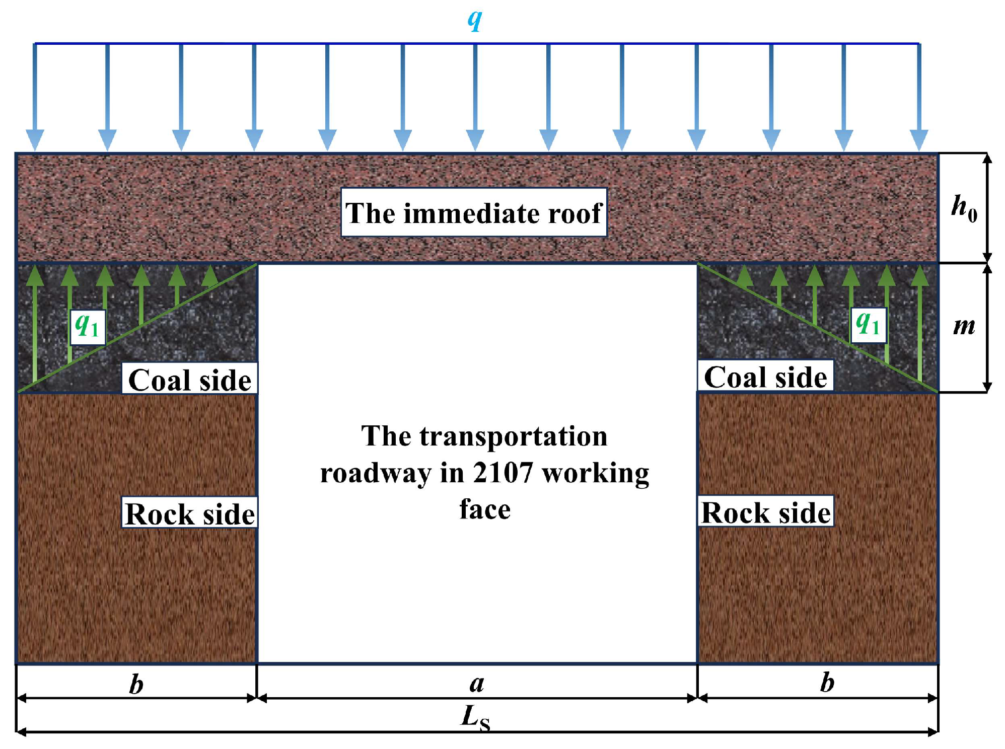
3.1. Analysis of Mechanical Properties of Layered Roof in Semi-Coal Rock Roadway of Shallow Thin Coal Seam

Research has proved that the surrounding rock of a roadway has the capacity to self-stabilize in a certain state, enabling it to resist the normal ground stress action [25]. An interactive relationship exists between the roadway’s two sides and its roof. The stability of the roadway’s two sides can diminish the extent of collapse in the roof area and reduce the difficulty associated with roof support. Similarly, the stability of the roof lessens the pressure on the roadway’s two sides, thereby fostering the stability of the two sides. The roof structure of the transportation roadway within the 2107 working face of Anzhe Coal Mine is characterized by a layered composition of sandy mudstone, siltstone, and mudstone, arranged sequentially. This structure is subjected to both vertical and horizontal ground stresses, rendering it susceptible to delamination [26]. The difference in the strength of coal and rock mass within a semi-coal rock roadway can exacerbate bending deformations in the roof strata. This can lead to increased extrusion at the top corners of the coal on both sides, causing further crushing and resulting in rib spalling. Consequently, this weakens the support provided by the two sides of the roadway, intensifying the separation between roof strata. Ultimately, if the tensile stress surpasses the limit of tensile strength, roof accidents may occur. The surrounding rock of the roof and the rock mass on both sides of the transportation roadway in the 2107 working face are hard and stable, and the coal of the two sides has local damage. According to the theory of bearing structure of roadway-surrounding rock [27], it can be seen that the fractured coal and rock mass still have residual strength and certain bearing capacity. In order to judge the stability of roadway-surrounding rock under the condition of a shallow-buried thin coal seam, it is necessary to analyze the interaction between the fractured coal of the two sides and the roof under the condition of no support.
It is postulated that the failure progression of the stratified roof occurs in an upward manner, layer by layer, starting from the first layer. Following the failure of the first layer, the mechanical models of the subsequent layers are assumed to be similar to the first layer, with the primary distinction being a variation in thickness. The roof structure is treated as an infinitely long plate [28], and the immediate roof strata are simplified as a plane strain model [29], with the rock masses on both sides considered as fixed bases, as illustrated in Figure 1. Within the diagram, a is the width of the roadway; b is the width of the fractured coal of the two sides, expressed as the maximum thickness of the coal loose circle of the two sides; m is the thickness of the coal of the two sides; q is the load of overlying strata; q1 is the fractured coal support load, which is regarded as non-equivalent load; h0 is the thickness of the immediate roof strata; γ0 is the average bulk density of the immediate roof strata; and Ls represents the length of the constructed mechanical model, that is, Ls = a + 2b. The roadway roof experiences fixed constraints from the rock mass at both ends, with equivalent reaction forces and bending moments at each end [30]. The fixed constraints at the left end are denoted by the force F0 and bending moment M0, while the release of the fixed constraints at the right end is substituted by the reaction forces Fa+2b and bending moments Ma+2b, resulting in a corresponding statically determinate beam [31], which is regarded as a cantilever beam Ls, as shown in Figure 2a. The shear force and bending moment of the beam are solved by the section method. The left end of the Ls section along the x section is studied, and the force is shown in Figure 2b.
It is obtained from the mechanical equilibrium in the vertical direction that:
q + γ 0 h 0 × a + 2 b = q 1 b
From the calculation, the shear force on the cantilever beam is:
F s = F 0 + 1 2 q 1 x q x ;   x ( 0 , b )
F s = F 0 + 1 2 q 1 b q x ;   x ( b , b + a )
F s = F 0 + 1 2 q 1 b + 1 2 q 1 x b a q x ;   x ( b + a , b + 2 a )
F 0 = q a + 2 b 2
The bending moment of each point on the corresponding cantilever beam is calculated by the shear force. According to the calculation results, the bending moment in the middle of the roadway roof is the largest:
M max = q 24 a + 2 b 2 q + γ 0 h 0 6 b a + 2 b
Let A = q/24, B = (q + γ0h0)/6, then:
M max = A a + 2 b 2 B b a + 2 b
The tensile strength of the roof σtmax in the unsupported condition is:
σ tmax = M max W = 6 A a + 2 b 2 B b a + 2 b h 0 2
In the formula, Mmax is the maximum bending moment of the roof and W is the section flexural modulus [32], W = h02/6.
From Ls = a + 2b, we get:
L s = 9 B 2 b 2 + 6 A h 0 2 σ tmax + 3 B b 6 A
a max = 9 B 2 b 2 + 6 A h 0 2 σ tmax + 3 B b 6 A 2 b
When the tensile stress on the roof does not exceed the tensile strength, a state of equilibrium is achieved between the overlying strata load and the support load of the fractured coal beneath it. In this balanced state, the fractured coal of the two sides can withstand the pressure from the roof above and maintain stability. By analyzing the above formula, amax is defined as the critical width of the semi-coal rock roadway in the shallowly buried thin coal seam, which is used to judge the stability of the two sides of the roadway. It is the maximum excavation width of the roadway where the coal sides of the semi-coal rock roadway in shallowly buried thin coal seam can maintain self-stability without support.
As the main part of the critical width calculation formula of the semi-coal rock roadway in shallowly buried thin coal seam, the thickness of the coal loose circle of the two sides directly affects its size, and it should be in a reasonable range to discuss the critical width. If the thickness of the coal loose circle of the two sides exceeds the allowable range for the instability of the surrounding rock, the critical width does not exist. The coal sides of the semi-coal rock roadway in the shallowly buried thin coal seam cannot maintain self-stability without support. To make the critical width meaningful, it is necessary to first determine the thickness of the coal loose circle of the two sides.
The loose circle of the surrounding rock is in a loose state of rupture caused by the stress of the surrounding rock exceeding the strength of the surrounding rock [33]. It belongs to a part of the stress limit equilibrium zone, and the width of the stress limit equilibrium zone increases approximately proportionally to the thickness of the coal seam [34]. The greater the thickness of the coal seam, the greater the stress limit equilibrium zone. During the excavation process of the semi-coal rock roadway, due to the continuous change in the thickness of the coal seam, the surrounding rock structure of the two sides of the roadway is constantly changing, and the thin coal seam generally has the problem of large thickness change and unstable occurrence [35]. Therefore, for the thin-coal-seam semi-coal rock roadway, it is necessary to discuss the relationship between the surrounding rock loose circle’s thickness and the coal seam’s thickness. Here, the thickness of the surrounding rock loose circle is approximately equal to the width of the fracture zone, and the theoretical thickness of the coal loose circle of the two sides is calculated by the width of the fracture zone.
Following the excavation of the roadway, the coal and rock mass located in the fracture zone and plastic zone of the roadway’s two sides reach a state of stress limit equilibrium. The cohesion and internal friction angle at the interface between the coal and rock mass within the semi-coal rock roadway are lower compared to those of the surrounding areas. Consequently, the coal within the limit equilibrium zone tends to be pushed out from the two sides of the roadway. By defining the horizontal rightward shear stress on the coal interface as τxy and setting the cohesion and internal friction angle of coal relative to the slip surface of the rock mass as c0 and φ0, respectively, with x0 representing the width of the stress limit equilibrium zone, σx the average horizontal stress across the entire thickness of the coal at x = x0, P0 the horizontal pressure on the interface between the stress limit equilibrium zone and the elastic zone, and P1 the support resistance of the coal side, a calculation model for the interface stress of the coal of the roadway side is formulated, as illustrated in Figure 3.
At the junction of the limit equilibrium zone and the elastic zone, the following is obtained:
σ y | x = x 0 = K γ H σ x | x = x 0 = C K γ H
In the formula, K is the stress concentration coefficient, γ is the average bulk density of overlying strata, H is the average burial depth of the roadway, and C is the lateral pressure coefficient at the elastic–plastic interface.
The limit equilibrium interface horizontal force is:
P = P 0 P 1 = m C K γ H P 1
The stress in the vertical direction of the coal in the plastic zone of the roadway side can be expressed as [36]:
σ y = P β 2 cosh β x sinh β x 0 c 0 cot φ 0
Among which:
x 0 = 1 2 β ln 2 c 0 + k γ H tan φ 0 + P β 2 c 0 + k γ H tan φ 0 P β
β = K s m E
In the formula, Ks is the tangential stiffness coefficient of the interface between the coal and the rock mass, which represents the shear force required to generate unit shear displacement on the surface of the coal per unit length. E is the elastic modulus of the coal.
When the pressure on the roof of the roadway surpasses the coal’s compressive strength, it causes the coal to fracture on both sides. This results in a reduction in vertical stress below the initial rock stress level, while the boundary conditions are met at the interface between the fractured zone and the plastic zone:
σ y | x = L b = γ H
Combining Equations (13) and (16), the width of the fracture zone Lb, that is, the thickness b of the coal loose circle of the two sides, is:
b = L b = 1 β ln B + B 2 1
In the formula, B = 2 sinh β x 0 P β c 0 + γ H tan φ 0 .
Here, only the relationship between the thickness of the coal seam m and the thickness of the coal loose circle b of the two sides is analyzed in detail. According to the geological data of the 2107 working face of Anzhe Coal Mine, the relevant parameters are taken as follows: γ = 2.45 t/m3, H = 90 m, K = 2, C = 1.1, E = 2.36 GPa, Ks = 1.2 GPa/m, and P1 is 0 without support. The cohesion and internal friction angle of the coal–rock interface measured by the direct shear test are c0 = 0.76 MPa and φ0 = 12°, respectively. The influence of coal seam thickness m on the thickness b of the coal loose circle of two sides is drawn, as shown in Figure 4.
It can be seen from Figure 3 that when the coal thickness is less than 0.7 m, the thickness of the coal loose circle of the two sides is within 1 m. When the coal thickness exceeds 0.8 m, the thickness of the coal loose circle of the two sides exceeds 1.5 m, and the increased range becomes larger, reaching the thickness range of the large loose circle. At this time, the lithology of the surrounding rock is unstable [37], and the coal sides of the semi-coal rock roadway cannot maintain self-stability without support. For the shallowly buried and extremely thin-coal-seam roadway with coal thickness below 0.7 m, the thickness of the coal loose circle of the two sides is small, and the lithology of the surrounding rock is relatively stable.
The transportation roadway of the 2107 working face in Anzhe Coal Mine belongs to the semi-coal rock roadway of shallowly buried extremely thin coal seam. The average thickness of the coal seam is 0.6 m, and the theoretical calculation result of the thickness of the coal loose circle of the two sides is 0.64 m. The average bulk density of overlying strata γ is 2.45 t/m3, the average bulk density of immediate roof strata γ0 is 2.25 t/m3, the average buried depth of roadway H is 90 m, the thickness of immediate roof strata h0 is 1.2 m, and the tensile strength of roof σtmax is 2.78 MPa. After calculation, the critical width amax of the transportation roadway in the 2107 working face is 3.02 m, and the actual width of the roadway is 2.4 m, which is less than the critical width. Therefore, the coal sides of the roadway can maintain self-stability without support. A mining roadway under similar conditions in this mine can refer to the critical width to set the upper limit of the excavation width of the roadway.

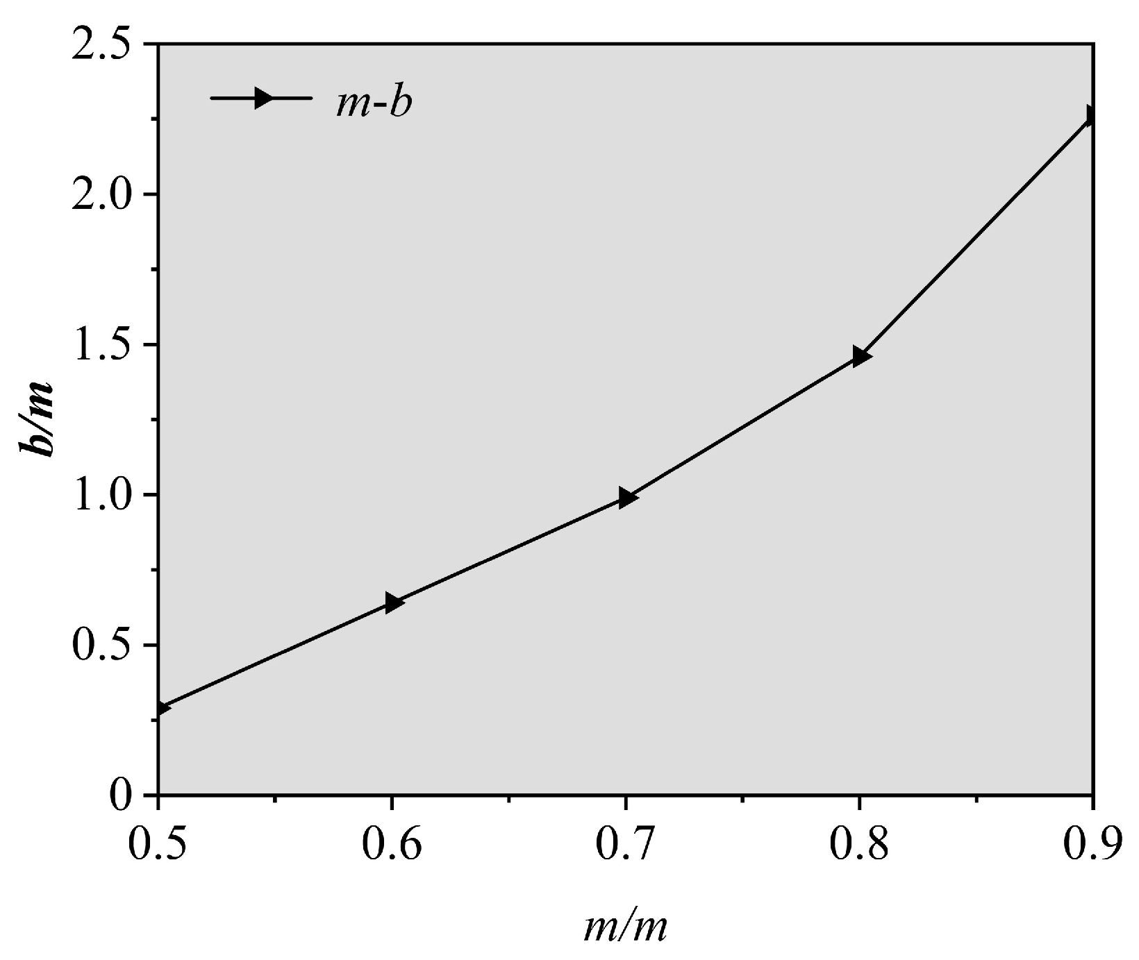
3.2. Analysis of Influencing Factors of Critical Width under Self-Stabilization Condition of Coal Side

When the theoretical thickness of the coal loose circle of the two sides of the semi-coal rock roadway in the shallow-buried thin coal seam is within the reasonable range of the critical width, the coal sides can maintain self-stability. At this time, the critical width amax is mainly related to the roof tensile strength σtmax, coefficients A and B, and the thickness of the immediate roof strata h0, where the coefficients A and B are determined by the buried depth of the roadway H. Therefore, only the three main influencing parameters of the roof tensile strength σtmax, the buried depth of the roadway H, and the thickness of the immediate roof strata h0 are specifically analyzed. With the transportation roadway of the 2107 working face as the background and taking the thickness b of the coal loose circle of the two sides as 0.64 m, the main parameters of influence on the critical width amax influence diagram are drawn, as shown in Figure 5.
It can be seen from Figure 5a that the tensile strength of the roof σtmax and the critical width amax are basically in a positive exponential relationship. When the tensile strength of the roof is larger, the critical width also increases, but the increase gradually decreases. The critical width is greater than the actual width of the roadway of 2.4 m, and the tensile strength of the roof σtmax is required to be above 1.5 MPa when other parameters remain unchanged. Therefore, when the tensile strength of the roof σtmax increases from 1.5 MPa to 6 MPa, the critical width amax increases from 2.40 m to 4.21 m, an increase of 42.99%.
It can be seen from Figure 5b that the buried depth of the roadway H and the critical width amax are basically in a negative exponential relationship. The larger the buried depth of the roadway, the smaller the critical width, and as the buried depth of the roadway increases, the critical width decreases. In the case of other parameters remaining unchanged, it is required that the buried depth of the roadway H be less than 150 m, so when the buried depth of the roadway H increases from 50 m to 150 m, the critical width amax decreases from 3.92 m to 2.47 m, which is reduced by 36.99%.
It can be seen from Figure 5c that the thickness of the immediate roof strata h0 and the critical width amax are also basically in a positive exponential relationship. The critical width increases with the increase in the thickness of the immediate roof strata, and the increase is increasing. In the case of other parameters remaining unchanged, it is required that the thickness of the immediate roof strata h0 be greater than 0.9 m. Therefore, when the thickness of the immediate roof rock layer h0 increases from 0.9 m to 1.8 m, the critical width amax increases from 2.42 m to 4.31 m, an increase of 43.85%.
Through analysis of the above examples, it can be seen that the calculation formula of the critical width of the semi-coal rock roadway in the shallow-buried thin coal seam has good applicability to the typical shallow-buried mine roadways in the Niuwu mining area and shallow-buried semi-coal rock roadways with coal thickness below 0.7 m under similar geological conditions. Through analysis of the control variable, the degree of influence of each parameter of the critical width calculation formula under the condition of self-stability of coal sides is: thickness of the immediate roof strata > tensile strength of the roof > buried depth of the roadway.

4. Field Test Verification of Loose Circle

4.1. Loose Circle Test Equipment
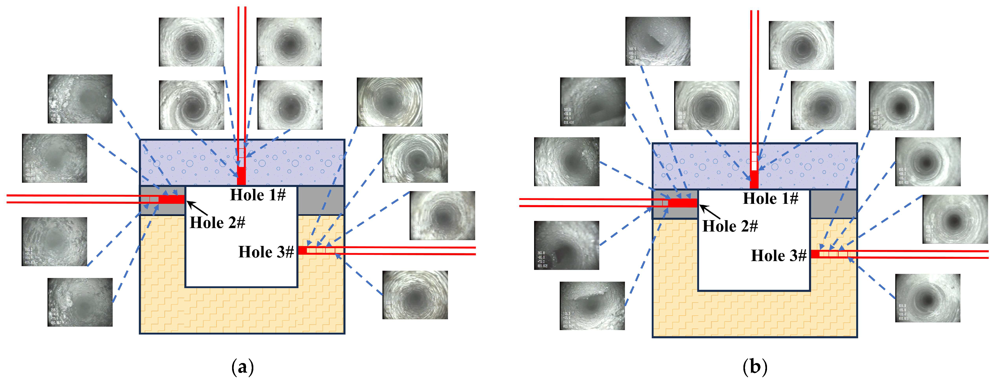
To confirm the precision of the calculated thickness of the coal loose circle and assess the stability of the surrounding rock, the loose circle test utilizes the intrinsically safe YTJ20 mine borehole peeper. This peeper is equipped with a 20-megapixel panoramic camera, as depicted in Figure 6.

4.2. Station Layout

In order to comprehensively reflect the characteristics of the loose circle of the surrounding rock in the transportation roadway of the 2107 working face, two sets of stations are arranged in the roadway. Stations P 1 to P 2 are arranged sequentially from the tunneling head of the roadway. Station P 1 is located at the head of the tunneling, 400 m away from the roadway mouth, and station P 2 is located at 50 m behind station P 1. The station layout is shown in Figure 7. Three boreholes are constructed in each station. Hole 1 is located in the middle of the roadway roof, hole 2 is located in the middle of the coal on the first side of the roadway, and hole 3 is located in the middle of the rock mass on the other side. The diameter of the borehole is 28–32 mm and the depth is 6 m.

4.3. Analysis of Measured Results

After the analysis and processing of the measured data, the results of the loose circle range of the roadway-surrounding rock of the two groups of station sections are attained, as shown in Figure 8, and these results are shown in Table 2. The gray solid and pattern-filling parts in the diagram represent the coal body and rock body, respectively. The red-filled part in each borehole represents the broken range of the inner wall of the borehole. A peep image is taken every 0.1–0.2 m from the borehole.
According to the field results of the transportation roadway in the 2107 working face, the rock mass of the two sides of the roadway belongs to the type I small loose circle [38], which is a stable surrounding rock and has no obvious weathering in the service life. The coal of the two sides belongs to a type II loose circle, which is a relatively stable surrounding rock. The measured values are in good agreement with the theoretical calculation results. The thickness of the coal loose circle of the two sides is much larger than the thickness of the rock mass loose circle. The thickness of the loose circle of the two sides should be based on the coal. The maximum thickness of the coal loose circle of the two sides is 0.7 m. The calculated critical width after the measured correction is 2.9 m. The actual width of the roadway is still less than the critical width, and the two sides can self-stabilize without support.

5. Optimization of Support Scheme

5.1. Supporting Scheme Correction and Parameters

Based on the classification and support suggestions of the roadway-surrounding rock loose circle proposed by Professor Dong Fangting [38] and the relevant provisions of Article 58 of the Coal Mine Safety Regulations (2022) [39], the actual width of the transportation roadway in the 2107 working face is less than the critical width. The two sides may not be supported, and the roof can only be supported by bolts.
The original support design of the transportation roadway in the 2107 working face adopts anchor beam support. If the roof is broken, anchor net support is adopted. The anchor rod is rounded steel with a diameter of 16 mm and a length of 1600 mm. Each anchor rod is anchored by two volumes of MSK2335 resin anchoring agent. The anchoring length is not less than 700 mm, and the exposed length is 50–100 mm. The tray uses an arched steel tray with a specification of 100 × 100 × 10 mm. The row spacing between the roof bolts is 700 × 900 mm, the spacing between the two sides of the bolts is 300 mm and 700 mm, respectively, and the row spacing is 900 mm. The anchor beam is a steel bar with a diameter of 10 mm and a length of 2.4 m. Each pair is welded into a group. Each group is fastened in the same straight line with the four anchors during support, and the steel bar is pressed inside the tray. The current support design removes the two-side support, and the roof support parameters are consistent with the original scheme. The specific section and support parameters are shown in Figure 9.

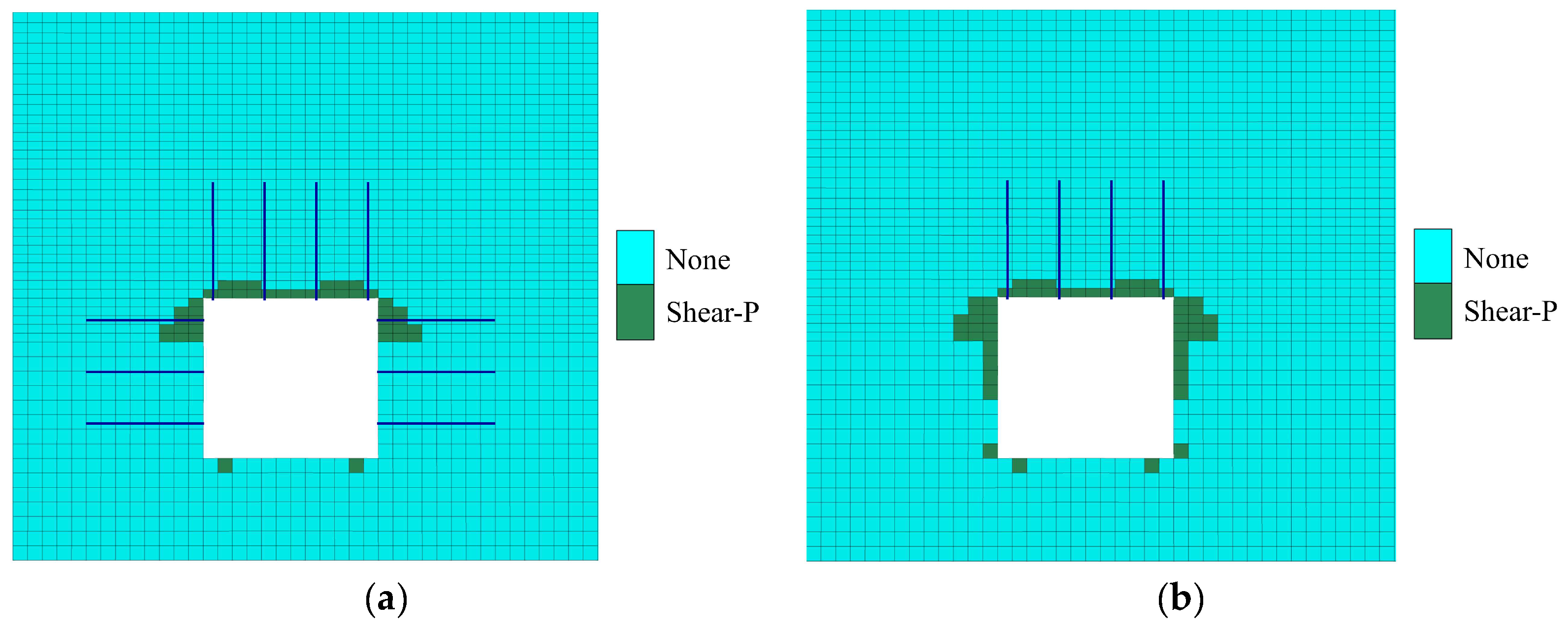
5.2. Numerical Model and Simulation Scheme

To verify the safety and rationality of the support scheme, a three-dimensional geologic numerical model of the transportation roadway of the 2107 working face was constructed using FLAC3D 6.0 software, as depicted in Figure 10. The model’s dimensions measure 40 m in the X direction, 20 m in the Y direction, and 30 m in the Z direction, with a total of 142,240 units and 152,878 nodes. The model is surrounded by fixed displacement constraints, with immovable boundaries at the base and unrestricted boundaries at the top. Reflecting the geological production conditions of the 2107 working face, a vertical stress of 1.50 MPa was applied to the upper boundary of the model to replicate the overlying strata’s weight. The initial stress equilibrium was determined using the Mohr–Coulomb constitutive model [40], with the rock mechanical parameters utilized detailed in Table 1.

5.3. Simulation Results and Analysis

From Figure 11, it can be seen that there is no significant change in the plastic zone of the surrounding rock in the test section of the roadway compared with the original support. The plastic zone of the roof under the current support scheme is 0.4 m, and the plastic zone of coal of the two sides is 0.6 m, which is consistent with the field measurement results. Under the radial tensile action of the bolts, there is no tensile stress area and no tensile failure.
Under the two support schemes, the numerical simulation results of the surface displacement of the roadway-surrounding rock are shown in Table 3.
Under the current support scheme, the convergence of the roof and floor of the roadway is 45.68 mm, and the convergence of the two sides is 19.25 mm. The deformation of the surrounding rock of the roadway is still very small when the two sides are not supported, which can meet the support requirements. The displacement field of the roadway-surrounding rock under the supporting scheme is shown in Figure 12.

6. Engineering Application Effect

The field engineering application was carried out in the test section of the transportation roadway of the 2107 working face. During the roadway excavation, the surface displacement monitoring station of the surrounding rock of the roadway was effectively monitored by the “cross point distribution method”. Items monitored included the relative displacement of the roof and floor and the two sides. Monitoring lasted for 1 month, and the results are shown in Figure 13.
According to the monitoring results of the surface displacement of the rock surrounding the roadway, the deformation had grown to large at day 15, then gradually decreased from day 15 to 25. After 25 days, the convergence of the roof and floor of the roadway and the two sides was basically stable. The maximum convergence of the roof and floor was 46.3 mm, and the maximum convergence of the two sides was 18.4 mm. The average deformation rates were 1.54 mm/day and 0.61 mm/day, respectively, and the deformation rate gradually decreased, indicating that the deformation of the rock surrounding the roadway had stabilized. The overall support effect of the roadway is shown in Figure 14, and there is no obvious deformation in the roadway. The optimized support scheme still effectively controlled the deformation of the surrounding rock, reduced the support cost to a certain extent, and accelerated the excavation, but at the same time reduced the safety factor of the roadway. Therefore, mine pressure monitoring of the roadway should be strengthened during the whole service period of the roadway. If the surface displacement of the surrounding rock increases significantly, reinforcement support should be carried out expeditiously and continuous monitoring should be carried out to ensure the stable, safe, and efficient use of the roadway.

7. Conclusions

(1)
Based on the structural characteristics of the layered roof of the transportation roadway in the 2107 working face of Anzhe Coal Mine, the roof is analyzed as an infinitely long plate, and the mechanical model of the layered roof of the semi-coal rock roadway in the shallowly buried thin coal seam is established. By analyzing the interaction between the fractured coal of the two sides and the roof, the calculation formula of the critical width of the semi-coal rock roadway in the shallow-buried thin coal seam is given to determine the stability of the two sides. The critical width of the semi-coal rock roadway in the shallow thin coal seam is defined as the maximum excavation width of the roadway where the coal sides can maintain self-stability without support. The thickness of the coal loose circle of the two sides increases with the increase in thickness of the coal seam. When the thickness is increased to a certain extent, the surrounding rock is unstable, and the critical width of the semi-coal rock roadway in shallow-buried thin coal seam does not exist.
(2)
By establishing the calculation model of the interface stress of the coal of the two sides, the expression of the thickness of the coal loose circle of the two sides is derived, and the theoretical thickness of the coal loose circle of the two sides of the 2107 working face is 0.64 m. Through case analysis, the calculation formula of the critical width of the semi-coal rock roadway in the shallow-buried thin coal seam has good applicability to typical shallow-buried mine roadways in the Niuwu mining area and shallow-buried semi-coal rock roadways with coal thickness below 0.7 m under similar geological conditions. The critical width under the condition of self-stability of the coal sides is mainly related to the three parameters of the tensile strength of the roof, the buried depth of the roadway, and the thickness of the immediate roof strata. The degree of influence of each parameter is: thickness of the immediate roof strata > tensile strength of the roof > buried depth of the roadway.
(3)
The loose circle of surrounding rock is measured on the coal and rock mass of the two sides of the roadway. The thickness of the rock mass loose circle of the two sides is 0.2 m, and the thickness of the coal loose circle of the two sides is 0.6–0.7 m. The measured values were consistent with the theoretical calculation results. The thickness of the loose circle of the two sides is based on the coal, and the maximum thickness of the coal loose circle of the two sides is 0.7 m. After calculation, the actual width of the roadway is 2.4 m, less than the critical width of 2.9 m, and the two sides of the roadway can maintain self-stability without support.
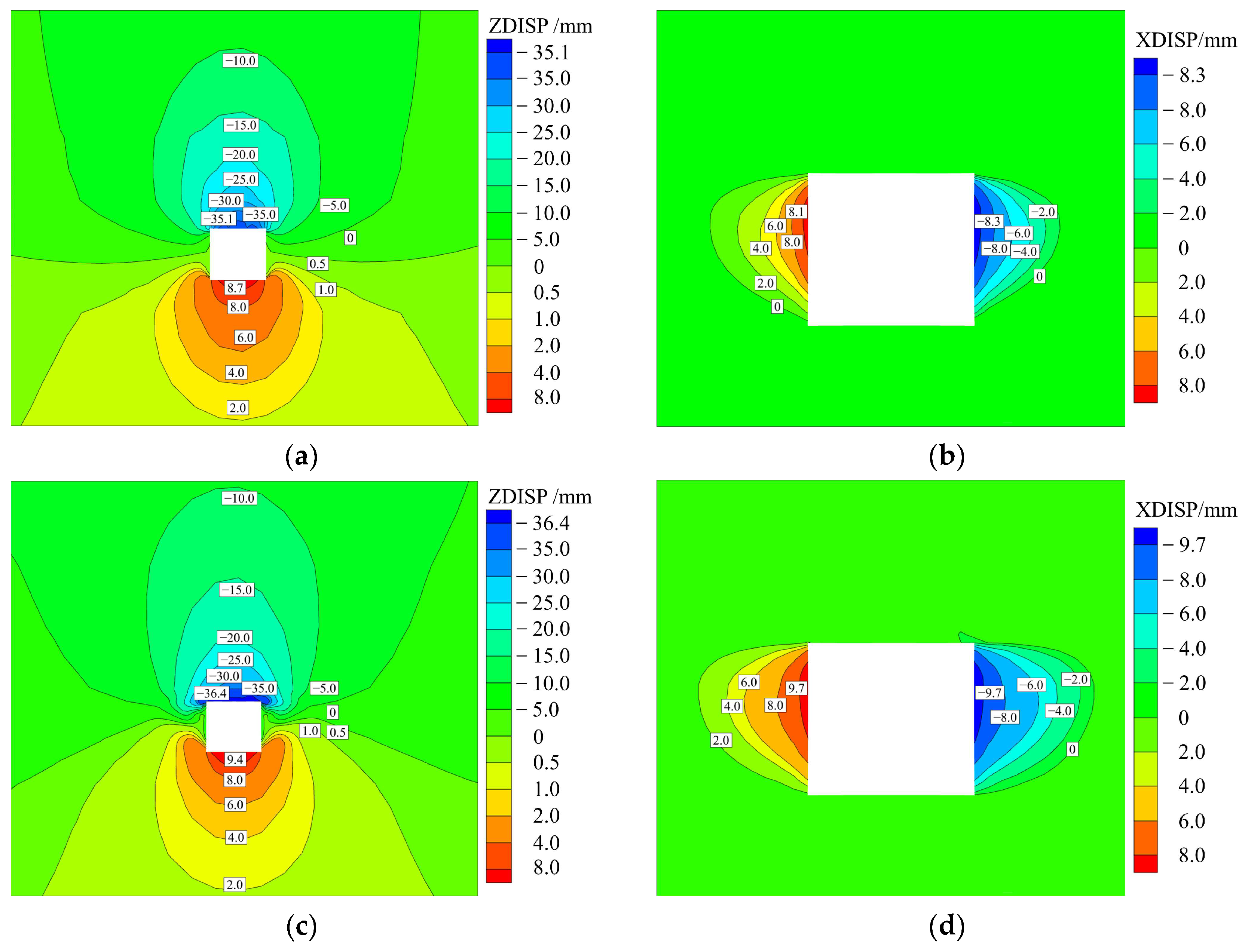
(4)
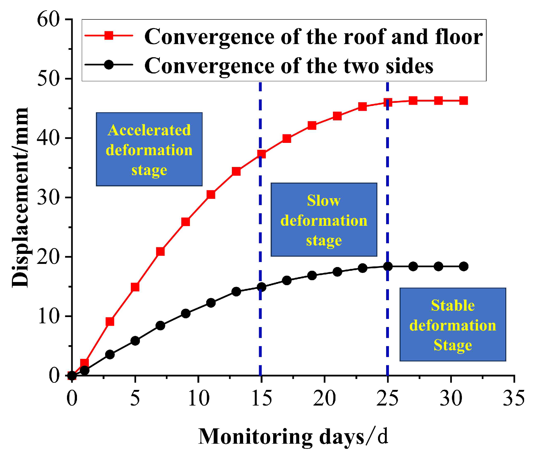
Based on the theory of surrounding rock loose circle support and critical width analysis, the support scheme is optimized, and its safety and rationality are verified by numerical simulation. The plastic zone of the roof is 0.4 m, the plastic zone of the two sides is 0.6 m, the convergence of the roof and floor is 45.68 mm, and the convergence of the two sides is 19.25 mm, which is not much different from the original support effect. The field engineering application shows that the period of influence of roadway excavation is about 25 days, the maximum convergence of the roof and floor is 46.3 mm, and the maximum convergence of the two sides is 18.4 mm. The optimized support scheme still effectively controls the deformation of the roadway-surrounding rock and can meet the requirements of safe production.

Author Contributions

Conceptualization, H.W. and Y.L.; methodology, L.L.; software, G.Y.; validation, L.J.; formal analysis, H.W.; investigation, Y.L.; resources, L.L.; data curation, Y.L.; writing—original draft preparation, H.W.; writing—review and editing, L.L.; visualization, Y.L.; supervision, G.Y.; project administration, H.W.; funding acquisition, H.W. All authors have read and agreed to the published version of the manuscript.

Funding

This research was funded by the National Natural Science Foundation of China (grant 51974231).

Institutional Review Board Statement

Not applicable.

Informed Consent Statement

Not applicable.

Data Availability Statement

Data will be made available on request.

Conflicts of Interest

The authors declare no conflicts of interest.

References

  1. Ren, B.; Ding, K.; Wang, L.G.; Jiang, C.Y.; Guo, J.X. Research on an Intelligent Mining Complete System of a Fully Mechanized Mining Face in Thin Coal Seam. Sensors 2023, 23, 9034. [Google Scholar] [CrossRef] [PubMed]
  2. Huang, Q.X.; He, Y.P.; Cao, J. Experimental Investigation on Crack Development Characteristics in Shallow Coal Seam Mining in China. Energies 2019, 12, 1302. [Google Scholar] [CrossRef]
  3. Huang, Q.X.; He, Y.P. Research on Overburden Movement Characteristics of Large Mining Height Working Face in Shallow Buried Thin Bedrock. Energies 2019, 12, 4208. [Google Scholar] [CrossRef]
  4. Huang, Q.X.; Zhou, J.L.; Mang, L.T.; Tang, P.F. Double key strata structure analysis of large mining height longwall face in nearly shallow coal seam. J. China Coal Soc. 2017, 42, 2504–2510. [Google Scholar]
  5. Wang, M.; Xiao, T.Q.; Gao, J.; Liu, J.L. Deformation mechanism and control technology for semi coal and rock roadway with structural plane under shearing force. J. Min. Saf. Eng. 2017, 34, 527–534. [Google Scholar]
  6. Li, C.Z. Study on surrounding rock deformation and control technology of mining roadway in shallow coal seam. Coal Chem. Ind. 2022, 45, 40–45. [Google Scholar]
  7. Han, C.; Yuan, Y.; Ding, G.; Li, W.; Yang, H.; Han, G. The Active Roof Supporting Technique of a Double-Layer Flexible and Thick Anchorage for Deep Withdrawal Roadway under Strong Mining Disturbance. Appl. Sci. 2023, 13, 12656. [Google Scholar] [CrossRef]
  8. Wang, X.J.; Tang, J.Z.; Li, Y.M.; Fu, Q. The Failure Law and Combined Support Technology of Roadways with Weak Surrounding Rock in Deep Wells. Appl. Sci. 2023, 13, 9738. [Google Scholar] [CrossRef]
  9. Wei, X.; Shahani, N.M.; Zheng, X.; Wang, J.; Wang, Y.; Chen, C.; Ren, Z. The Retention and Control Technology for Rock Beams in the Roof of the Roadway: A Case Study. Processes 2023, 11, 1593. [Google Scholar] [CrossRef]
  10. Liu, C.; Wang, F.T.; Zhang, Z.Y.; Zhu, D.X.; Hao, W.H.; Tan, T.K.; Zhang, X.T.; Zhu, C.G. Surrounding Rock Deformation Mechanism and Control Technology for the Roadway in the Fault-Disturbed Zone under Special-Shaped Coal Pillars. Processes 2023, 11, 3264. [Google Scholar] [CrossRef]
  11. Zhu, R.J.; Yue, X.Z.; Gao, Y.D.; Liu, X.S.; Li, X.B.; Xie, C.C.; Wang, K. Study on the Stress Evolution and Strengthening Support Timing of the Retracement Channel under the Super-Thick Nappe. Sustainability 2023, 15, 15677. [Google Scholar] [CrossRef]
  12. Jin, G.; Wang, L.G.; Li, Z.L.; Zhang, J.H. Study on the gateway rock failure mechanism and supporting practice of half-coal-rock extraction roadway in deep coal mine. J. Min. Saf. Eng. 2015, 32, 963–967. [Google Scholar]
  13. Yue, W.J.; Feng, T.; Wang, W.J.; Liu, H.; Ma, P.Y.; Wang, P.; Li, R.H. Deformation mechanism control principle and technology of soft half coal rock roadway. Chin. J. Rock. Mech. Eng. 2014, 33, 658–671. [Google Scholar]
  14. Wang, J.X.; Sheng, J.; Chen, Z.H. Study into Damage Mechanics of Anchoring Reinforced Roadway in Jointed Coa l Rock Mass. J. Min. Saf. Eng. 2009, 26, 203–207. [Google Scholar]
  15. Duo, S.H.; Yue, W.J.; Zhang, T.L.; Zhao, J.F. Deformation mechanism and support technology of soft and extremely fractured coal-rock roadway with large deformation. Coal Sci. Technol. 2016, 44, 15–21. [Google Scholar]
  16. Yan, D.H.; Cheng, Z.H.; Liu, Y.; Jiang, X.Q.; Du, Z.F.; Yao, J.G. Study on bolt support technology of semi coal rock roadway in Shaqu Mine. Coal Sci. Technol. 2020, 48 (Suppl. S1), 12–17. [Google Scholar]
  17. Wang, H.; Li, Y.C.; Zhao, W.J. Excavation stability analysis and support parameter evaluation of semi-coal rock roadway. Saf. Coal Mines 2008, 11, 56–59. [Google Scholar]
  18. Li, J.F.; Guo, W.Y.; Zhang, C.L.; Cheng, C.X.; Liu, J.K.; Zhou, G.L. Supporting Technology of Fully Mechanized Half-coal Rock Mining Roadway in Thin Seam. Saf. Coal Mines 2013, 44, 97–103. [Google Scholar]
  19. Qiu, W.H.; Kong, L.H.; Zhao, S.K.; Zhang, S.X.; Wang, H.M. Failure Characteristics and Control of Surrounding Strata of Coal and Rock Roadway. Saf. Coal Mines 2017, 48, 202–205. [Google Scholar]
  20. Cui, Q.L.; Wu, J.X. Parameters Optimization of Bolting in Mining Coal-Rock Roadway Under Shallow Overburden. Coal Eng. 2015, 47, 48–50. [Google Scholar]
  21. Li, Z.L.; Wang, L.G.; Lu, Y.L.; Li, W.S.; Wang, K. Effect of principal stress rotation on the stability of a roadway constructed in half-coal-rock stratum and its control technology. Arab. J. Geosci. 2021, 14, 292. [Google Scholar] [CrossRef]
  22. Wang, H.; Jiang, C.; Zheng, P.Q.; Zhao, W.J.; Li, N. A combined supporting system based on filled-wall method for semi coal-rock roadways with large deformations. Tunn. Undergr. Space Technol. Inc. Trenchless Technol. Res. 2020, 99, 103382. [Google Scholar] [CrossRef]
  23. Wang, E.Y.; Chen, X.D.; Yang, X.J. Research and Application of an Innovative 110 Mining Method in Gob-Side Half Coal Rock Entry Retaining. Shock. Vib. 2021, 2021, 8228604. [Google Scholar] [CrossRef]
  24. Pan, B.; Yue, W.J.; Shen, W.B. Experimental Study on Energy Evolution and Failure Characteristics of Rock–Coal–Rock Combination with Different Height Ratios. Geotech. Geol. Eng. 2020, 39, 425–435. [Google Scholar] [CrossRef]
  25. Huang, Q.X.; Zheng, C. Theory of self-stable ring in roadway support. Rock. Soil. Mech. 2016, 37, 1231–1236. [Google Scholar]
  26. Wang, H.S.; Zhang, D.S.; Li, S.G.; Wang, L.; Wu, L.Z. Rational width of narrow coal pillar based on the fracture line location of key rock B in main roof. J. Min. Saf. Eng. 2014, 31, 10–16. [Google Scholar]
  27. Wang, B.; Wang, W.J.; Zhao, F.J.; Fan, B.J.; Tang, H.X. Study of bolt anchoring effect based on self-bearing characteristics of roadway surrounding rock. Rock. Soil. Mech. 2014, 35, 1965–1972. [Google Scholar]
  28. Li, L.; Bai, J.B.; Xu, Y.; Xiao, T.Q.; Wang, X.Y.; Zhang, K.X. Research on rock control of roadway with complex roof driven along goaf. J. Min. Saf. Eng. 2011, 28, 376–383. [Google Scholar]
  29. Bai, J.B.; Hou, C.J. On bolting support of roadway in extremely soft seam of coal mine with complex roof. J. Rock. Mech. Geotech. Eng. 2001, 1, 53–56. [Google Scholar]
  30. Qian, M.G.; Shi, P.W.; Xu, J.L. Ground Pressure and Strata Control, 2nd ed.; China University of Mining and Technology Press: Beijing, China, 2015; pp. 75–76. [Google Scholar]
  31. Wang, Z.X.; Hou, K.P.; Sun, H.F. Study on limit span of roadway. China Min. Mag. 2023, 32, 112–117. [Google Scholar]
  32. Liu, Y.T.; Han, Q.Q.; Pang, T.; He, H.D.; Zhang, S.J. Equalizing Reinforcement Support Design and Application in Stratified Roof Roadway. Saf. Coal Mines 2014, 45, 139–141. [Google Scholar]
  33. Song, H.W.; Guo, Z.H.; Zhou, R.Z.; Dong, F.T.; Zhang, S.J. The basic viewpoint of roadway support theory in a loose circle of surrounding rock. Mine Constr. Technol. 1994, 45, 3–9. [Google Scholar]
  34. Hou, C.J.; Ma, N.J. Discussion on stress and limit equilibrium zone of coal body in two gangs of coal seam roadway. J. China Coal Soc. 1989, 4, 21–29. [Google Scholar]
  35. Gao, S.G.; Gao, D.Y.; OuYang, Y.B.; Chai, J.; Zhang, D.D.; Ren, W.Q. Intelligent mining technology and its equipment for medium thickness thin seam. J. China Coal Soc. 2020, 45, 1997–2007. [Google Scholar]
  36. Yu, Y.X.; Hong, X.; Chen, F.F. Study on load transmission mechanism and limit equilibrium zone of coal-wall in extraction opening. J. China Coal Soc. 2012, 37, 1630–1636. [Google Scholar]
  37. Guo, Z.H.; Dong, F.T. Surrounding rock loose circle and roadway support. J. Min. Saf. Eng. 1995, Z1, 111–114. [Google Scholar]
  38. Dong, F.T.; Song, H.W.; Guo, Z.H.; Lu, S.M.; Liang, S.J. Support theory of roadway surrounding rock loose circle. J. China Coal Soc. 1994, 1, 21–32. [Google Scholar]
  39. State Administration of Work Safety. Coal Mine Safety Regulations; Coal Industry Press: Beijing, China, 2022. [Google Scholar]
  40. Pu, L.; Liu, Y.J.; Cai, Y.B.; Sun, Z.; Zhou, X. Study on Active Support Parameters for Surrounding Rock with Ultra-Large Span Open-Off Cut in Thick Coal Seam. Appl. Sci. 2023, 13, 12804. [Google Scholar] [CrossRef]
Figure 1. The 2107 working face transport roadway layered roof mechanical model diagram.
Sustainability 16 05689 g001
Figure 2. Mechanical model analysis diagram. (a) The corresponding statically determinate beam of the mechanical model of the cantilever beam; (b) section stress analysis.
Sustainability 16 05689 g002
Figure 3. Coal interface stress calculation model of roadway side.
Sustainability 16 05689 g003
Figure 4. The relationship between the thickness m of the coal seam and the thickness b of the coal loose circle of the roadway side.
Sustainability 16 05689 g004
Figure 5. Relationship between main influence parameters and amax. (a) The relationship between σtmax and amax (H = 90 m h0 = 1.2 m); (b) The relationship between H and amax (σtmax = 2.78 MPa h0 = 1.2 m); (c) The relationship between h0 and amax (σtmax = 2.78 MPa H = 90 m).
Sustainability 16 05689 g005
Figure 6. YTJ20 borehole peeper.
Sustainability 16 05689 g006
Figure 7. Schematic diagram of station layout.
Sustainability 16 05689 g007
Figure 8. The 2107 working face transport roadway-surrounding rock loose circle results. (a) Station P1; (b) station P2.
Sustainability 16 05689 g008
Figure 9. Roadway test section support section diagram.
Sustainability 16 05689 g009
Figure 10. Three-dimensional numerical model.
Sustainability 16 05689 g010
Figure 11. Distribution of plastic zone of roadway-surrounding rock. (a) Original support plastic zone; (b) current support plastic zone.
Sustainability 16 05689 g011
Figure 12. Displacement cloud diagram before and after optimization of the support scheme. (a) Vertical displacement of original support; (b) horizontal displacement of original support; (c) vertical displacement of optimized support; (d) horizontal displacement of optimized support.
Sustainability 16 05689 g012
Figure 13. Displacement variation curve of rock surface surrounding the roadway.
Sustainability 16 05689 g013
Figure 14. Supporting effect of roadway test section: (a) 400 m of roadway; (b) 600 m of roadway; (c) 850 m of roadway; (d) head of roadway excavation.
Sustainability 16 05689 g014aSustainability 16 05689 g014b
Table 1. Mechanical parameters of coal and rock.
Rock FormationElastic
Modulus/GPa
Poisson
Ratio
Internal
Friction
Angle/(°)
Cohesion/MPaTensile
Strength/MPa
Density
/kg·m−3
Fine-grained sandstone16.670.1738.1917.904.222500
Medium-grained sandstone16.550.1940.3216.138.442400
Mudstone3.120.1836.002.851.362230
Siltstone19.220.1436.6012.253.362600
Sandy mudstone8.420.1232.406.892.782460
Coal seam2.360.1135.192.270.881350
Fine-grained sandstone16.670.1738.1917.904.222500
Medium-grained sandstone16.550.1940.3216.138.442400
Table 2. The 2107 working face transport roadway-surrounding rock loose circle results.
StationBore HoleThickness of Loose CircleSurrounding Rock ClassificationLithology of Surrounding Rock
P 1Hole 10.4 mStabilizing surrounding rock
Hole 20.6 mRelatively stable surrounding rock
Hole 30.2 mStabilizing surrounding rock
P 2Hole 10.2 mStabilizing surrounding rock
Hole 20.7 mRelatively stable surrounding rock
Hole 30.2 mStabilizing surrounding rock
Table 3. Surrounding rock surface displacement of roadway.
SchemeRoof Subsidence
/mm
Floor Heave
/mm
Left Side
/mm
Right Side
/mm
Original support35.098.658.078.21
Optimized support36.379.319.619.64
Disclaimer/Publisher’s Note: The statements, opinions and data contained in all publications are solely those of the individual author(s) and contributor(s) and not of MDPI and/or the editor(s). MDPI and/or the editor(s) disclaim responsibility for any injury to people or property resulting from any ideas, methods, instructions or products referred to in the content.

