Article

Augmented Two-Stage Hierarchical Controller for Distributed Power Generation System Powered by Renewable Energy: Development and Performance Analysis

by
Javed Khan Bhutto
Department of Electrical Engineering, College of Engineering, King Khalid University, Abha 61421, Saudi Arabia
Sustainability 2024, 16(14), 5872; https://doi.org/10.3390/su16145872
Submission received: 28 April 2024 / Revised: 30 June 2024 / Accepted: 4 July 2024 / Published: 10 July 2024

Abstract

:
The sustainable development of an area is highly reliant on a reliable electrical energy supply. Microgrids are important in integrating distributed energy resources (DERs) using power electronic converters. However, microgrid control becomes challenging with the increasing number of distributed generators and loads. With the conventional droop control method, power contributions from DER converters cannot be accurately shared due to a mismatch of line impedances. In this paper, an augmented hierarchical control mechanism is proposed to solve the issues mentioned above. This hierarchical control mechanism consists of primary and secondary controllers. The primary stage utilized the droop controller to improve optimal power flow, mainly for the resistive network. The secondary stage is based on an improved methodology to compensate for the voltage and frequency variations during small and large signal disturbances. Moreover, the modelling and analysis for PMSG-based wind energy conversion systems are also presented. The response of the primary controller for active and reactive power sharing is investigated. The analysis emphasizes the demonstration of optimal power-sharing under normal and abnormal conditions for the considered load. Finally, the suggested robust controller’s performance is evaluated in a MATLAB environment, and simulation results show the proposed scheme’s superiority under different operating conditions. The frequency is stable at 50 Hz after a 50 KW load is added.

1. Introduction

Energy from sources that can support present operations without jeopardizing future energy needs or mitigating climate change is required for development to be deemed sustainable. The energy needs of the present are satisfied by sustainable energy sources, which also preserve the potential for future power generation. There has been a major shift in the energy landscape due to growing worries about resource depletion, climate change, and environmental degradation. Using power electronic converters in this situation requires integrating distributed energy resources (DERs) in a significant way. However, as the number of distributed generators and loads increases, controlling an integrated system becomes more difficult [1,2]. Droop control, which offers autonomous and balanced power distribution, was proposed by researchers for microgrids. Unfortunately, because of a mismatch in line impedances, power contributions from DER converters cannot be precisely shared with the usual droop control method. A communication-based, centralized control mechanism is essential to resolving the aforementioned problems. The primary and secondary controllers of an improved communication-based hierarchical control mechanism are presented in this study. The droop controller is employed by the primary stage to enhance the best power flow, primarily for the resistive network. The secondary stage uses an enhanced process to adjust for voltage and frequency fluctuations caused by both minor and major signal disruptions. Lastly, the performance of the introduced robust controller is assessed in a MATLAB environment, and outcomes findings demonstrate the excellence of the recommended technique in various operational scenarios. A ground-breaking technology called microgrids (MGs) has been developed to improve the infrastructure for electric power.

1.1. Literature Review

In today’s scenario, the energy sector is steadily moving toward the era of smart grids (SGs) to attain greener, resilient, reliable, and efficient power networks. Unlike a single DG unit, microgrids can provide better energy management over distribution networks and ensure better reliability for critical loads, especially when main-grid power is unavailable. The microgrid concept is crucial for integrating DG units into the grid. Both islanded mode (IM) and grid-connected mode (GCM) should be supported by a microgrid. Microgrids have a range of uses, such as controlling the flow of electricity through distribution networks in the event of a grid failure [3]. The power flow issue for islanded droop-regulated microgrids has been written about by many authors. Because droop management is resilient and does not require high-bandwidth transmission, it is widely used for DGs operating in parallel. Droop control makes it possible for DGs to run concurrently. The primary factors influencing droop control are the load characteristics and the line’s impedance. Droop control is unreliable because differences in line impedance can affect voltage and frequency. By mimicking suitable line impedance behaviors, the virtual impedance (VI) can be utilized in conjunction with droop control to increase dependability. In contrast, the VI control methods rely on the utilization of real-time line impedance data, which is not always available. Furthermore, it might not be feasible to adjust the inverter’s output impedance to be mostly inductive or resistive using VI approaches because the line might contain both inductive and resistive components. A hierarchical control system for effective power management and coordinated control of a solitary MICROGRID was presented in [4]. The secondary stage uses a high-bandwidth communication-based controller to compensate for the active power management handled by the primary stage. [5] proposed a hybrid energy storage system control mechanism with a self-recovery capacity for the DC bus voltage. Proportional-integral regulation was used to reduce the DC bus drop voltage, and virtual droop control was utilized to achieve low- and high-frequency power decomposition. With this approach, energy supply and storage might remain consistent even in the face of frequent power spikes. Simulations using MATLAB/Simulink (R2023b) were used to test the proposed control strategy. In order to address demand generation inconsistency and DC bus voltage constraints, a novel method based on variable structural management for power-sharing between batteries and supercapacitors was introduced in [6]. The solution outperformed conventional control methods in terms of peak DC bus voltage changes, as demonstrated by the simulation results. The results were experimentally verified using a real-time hardware-in-loop simulator based on field-programmable gate arrays. A DC micro-grid power-sharing plan was proposed in [7] to guarantee that distributed battery energy units maintain a steady state of charge (SoC). The droop coefficients were computed taking into account the SOC values, and accurate power sharing was achieved by employing BEU virtual power ratings that were adjusted to SOC levels. As part of a power-sharing and control system, [8] proposed a fuel cell stack, an ultra-capacitor module, a solar array, and other loads. The optimal power sharing and energy management system was in charge of overseeing and managing the overall coordination of the PV and FC systems, as well as the loads and controllers of the electrolyzes and ultra-capacitor storage systems. A linear weighted summation approach with adjustable weights was presented in [9] as a method for balancing the two main optimization goals of a hybrid energy storage system, namely SoC reserve and power loss reduction. The technique aims to reduce energy loss, preserve the SC charge level, and distribute power among multiple energy storage components while solving a MOP and achieving the best ratio of power distribution between the SC and the battery.
Assuming that communication was possible, it was strongly advised to use the secondary control to support the droop control by adjusting for variations in frequency and voltage [10,11]. Other studies have been carried out under the same general topic using the hierarchical control structure, which consists of primary, secondary, and, in some cases, even tertiary control [12,13,14]. A hierarchical control system was described in [15] for the coordinated management and active power control of a single microgrid. The principal step was intended to perform active power management, while the secondary step was set up to employ high-bandwidth communication to counteract fluctuations in voltage and frequency. An improved droop mechanism with a simple communication link was described in [16] to maximize the sharing of reactive power in an independent microgrid. There were two actions involved in the execution of this approach. A low-bandwidth signal is first utilized to adjust the droop control’s voltage bias. In the second phase, the voltage magnitude is raised to its starting value by making up for the voltage drop. In [17], a hierarchical control for frequency stability in different microgrids was introduced. Three temporal zones were created for the control structure: the first, second, and third zones, which were categorized as short-term, long-term, and transient perturbations, respectively. In [18,19], the centralized or decentralized hierarchical methods for a microgrid were discussed, and subsequent directions for microgrid hierarchical control were forecast. The majority of study investigations for islanded microgrids that are published in the literature did not take into account the smooth transfer between both linked and isolated modes [20]. Moreover, the P V / Q f droop technique—which is the recommended approach to apply in cases when the circuit impedance is predominantly resistive—was not covered concerning the hierarchical control structure. The idea of distributed collaborative operation of parallel renewable-based DG is presented in [21], whereas the control and management of distributed energy systems are discussed in [22]. Hierarchical MPC control for improved performance of MG is present in [23].

1.2. Contributions

The introduction of some renewable energy sources is a key source of sustainable energy due to the increasing electric load demands in recent years. As a result, non-traditional energy sources such as solar and wind energy must be used to meet energy demands. This work proposes the modelling and simulation of a wind energy conversion system to achieve a continuous power supply. The goal of this technology’s development is to enhance power transfer to the load in a range of weather scenarios. Additionally, a MATLAB/Simulink model and simulation of a microgrid based on a wind energy conversion system are evaluated for multiple case studies. Presenting a hierarchical controller for enhancing frequency response in several operating modes is the main objective of this work. Additionally, the suggested controller enables the best possible power sharing amongst DGs in a range of operating modes. The results show how the recommended controller’s insight features help to maintain the best possible power flow under different conditions.
  • Proposes the modelling and simulation of a wind energy conversion system to achieve a continuous power supply.
  • Design a two-stage hierarchical controller for enhancing frequency response in several operating modes.
  • A MATLAB/Simulink model and simulation of a microgrid based on a wind energy conversion system are evaluated for multiple case studies.
This is how the rest of the article is organized: Section 2 describes the detailed construction of the WECS-based Microgrid Model. The control strategies for parallel-functioning DGs are presented in Section 3. These include hierarchical control of microgrids with primary and secondary control and operating modes of transition, droop control, and virtual impedance droop control. Section 4 presents the case study and related findings. Section 5 concludes this task and is followed by references.

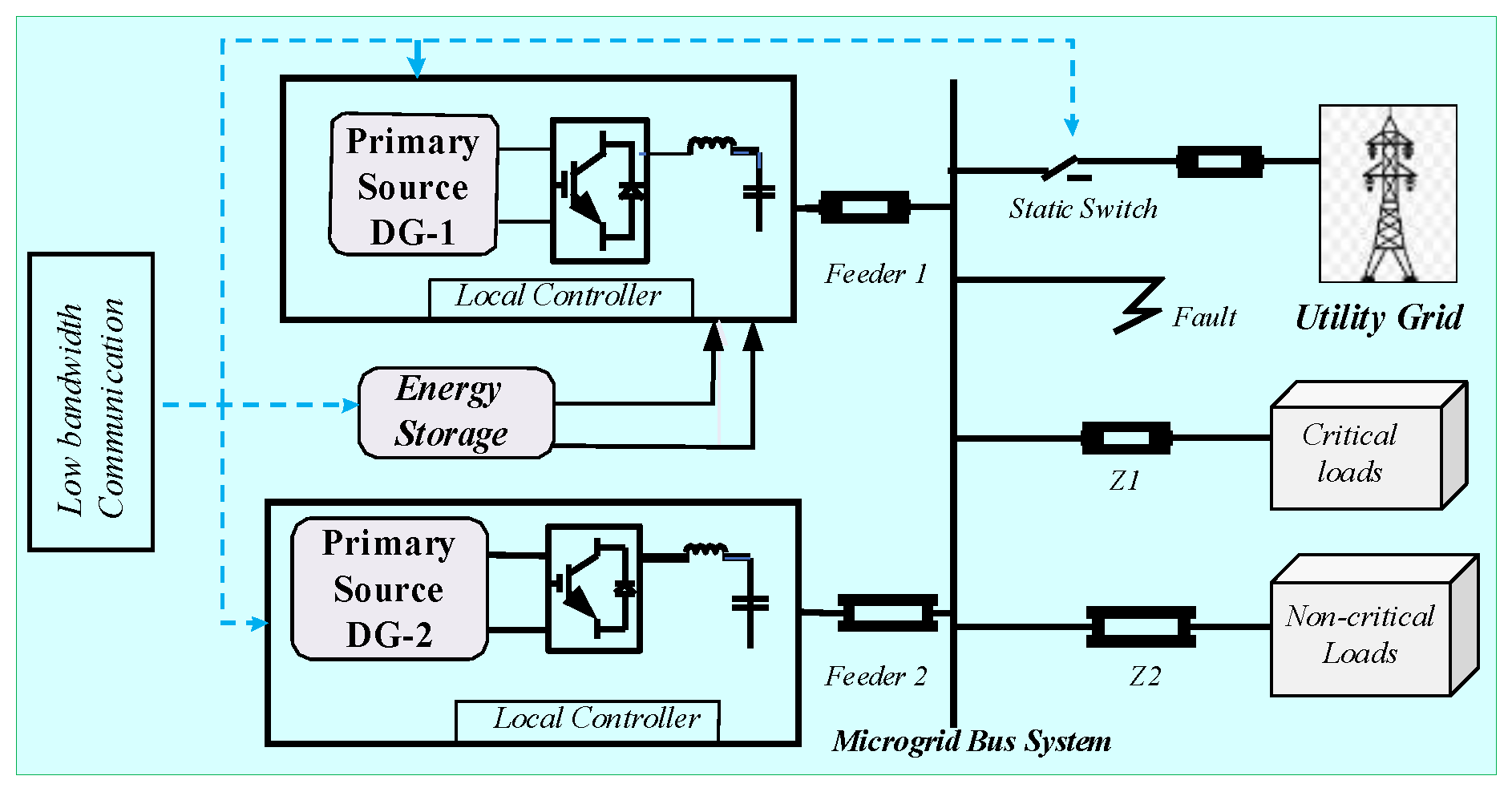
2. WECS-Based Microgrid Model

Figure 1 represents the layout of the proposed system, where wind resources are used to generate a sustainable power supply. For integrating DG units into a microgrid, it is essential to understand the operational characteristics of the DG units and microgrid during GCM and IM modes of operation. The typical grid-tied microgrid configuration, consisting of two types of DG units, loads, and battery energy storage system (BESS), is considered and is depicted in Figure 1. The aggregated model is considered and modelled in MATLAB/SIMULINK software (R2023b) environment. To keep the voltage level constant at the load end, the pulses of the inverter are varied using a controller and pulse width modulation (PWM) technique. The system uses a simple LC filter, which maintains the power quality at the load side within IEEE Std 2030.7-2017 [24].

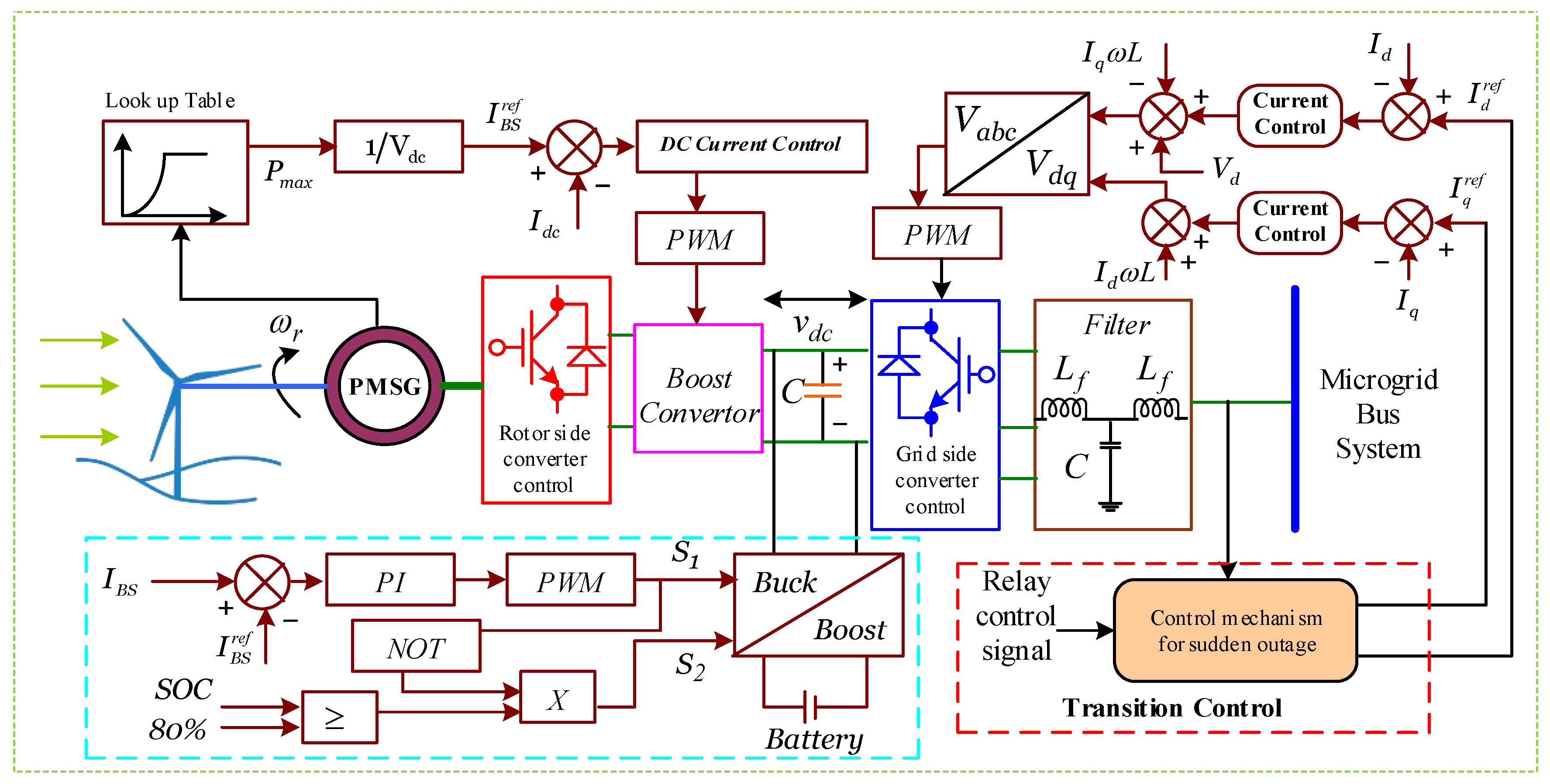
2.1. Modelling of ESSs-Backed DG1

The analogous model of the DG unit integrated with an energy storage system linked to the PCC and equipped with an output LCL filter is depicted in Figure 2. This arrangement functions as a master unit; the structure is inexpensive and simple. The master units are typically categorized as DG, BESS, or BESS integrated with DG [25]. The microgrid may only run in islanded mode for a brief period of time when BESS is utilized as the master controller because BESS gradually drains its power [26]. Consequently, in this work, the combination of DG and ESS is modelled to function as master controllers. Renewable energy sources like solar and wind turbines are best suited for this strategy [27]. The master units DG or ESS of a microgrid in island mode function in V/f control mode, setting both voltage and frequency references for other DGs in PQ control mode. The main grid provides voltage and frequency references for the microgrid in order for the grid-tied operation of the microgrid system to function. In the event of a utility-side anomaly, the micro-grid can quickly transition from grid-tied to island mode [28].
The modelling of DG1 is shown in Figure 2; here, the boost converter’s control utilizes a lookup table of wind turbine characteristics to attain maximum power. The control of the buck/boost converter simultaneously attempts to control the battery current on both sides and maintain a constant DC-link voltage. The battery will be required as long as DG1 controls voltage and frequency in islanded mode. With a rated power of 300 kWh and an operating voltage of 800 V, the current I b s r e f is set to be:
I b s r e f = K p , b s 800 V b s + K p , b s 800 V b s d t
The K p , b s and K p , b s are the gains of the current controller, and V b s is the operating voltage of the battery energy storage. During islanded mode, the grid-side converters maintain V / f constant for the microgrid load. On the other hand, the power converter has the necessary active power to charge the battery during GCM and transfers excess active power to the grid. The current references are produced by two distinct current control loops. During the autonomous mode of operation, two-stage hierarchical control is used in the first loop to modify the current references [16,29]. In grid-tied mode, the second loop primarily depends on the battery’s charge status (SOC). The next part provides a general explanation of both control loops. The voltage and current references are transformed to d q form. Ignoring the impact of the filter capacitor yields the output voltage from the voltage control loop [30].
V d o u t = V d + K i d I d r e f I d d t ω L i q + K p d I d r e f I d
V q o u t = ω L i q + K i q I q r e f I q d t + K p q I q r e f I q
The filter inductor’s compensation element is denoted by ω L i q , while the control gains for the direct and quadrature current controllers are represented by K p d , K i d , K p q and K i q .

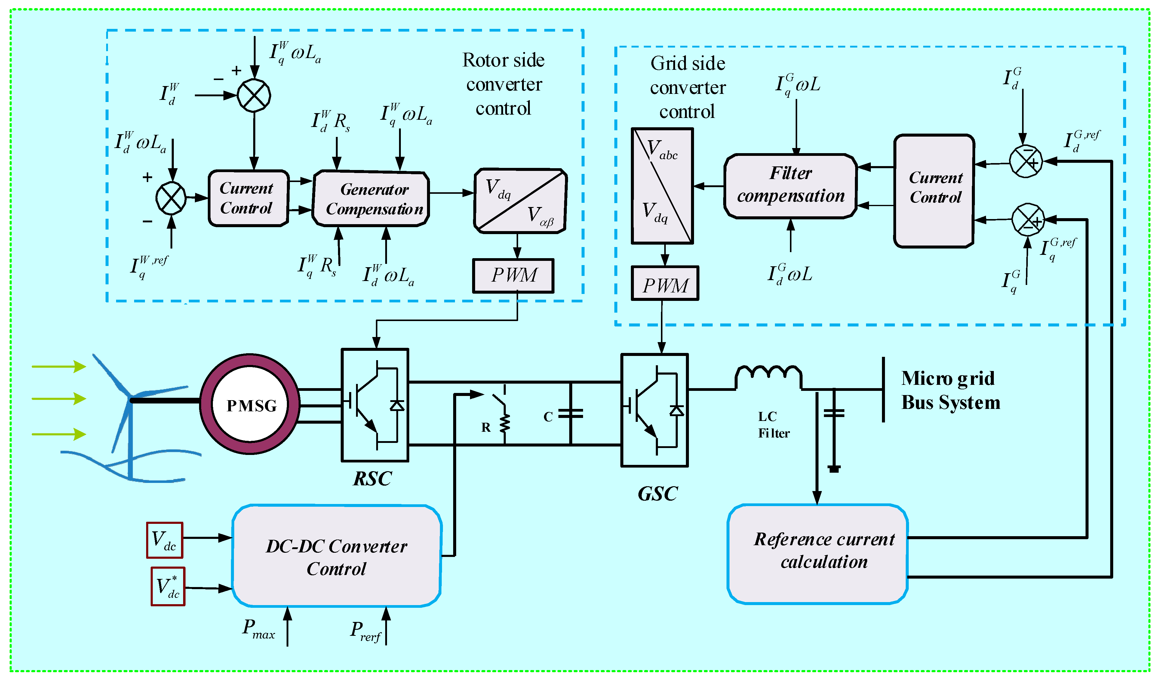
2.2. Control Scheme for PMSG Based DG2

DG2 used regulated converters on both sides of the apparatus, as seen in Figure 3. The wind turbine’s maximum power is extracted via the stator side converter. The used wind turbine’s reference torque can be expressed as [31,32]
T r e f e = K p T ω r r r f ω r + K i T ω r r r f ω r d t
where ω r r r f is speed reference of the rotor, and K p T , K i T , are the torque regulator’s control gains. Using the rotor speed ω r as indicated in Figure 3, the maximum active current I q is calculated using the MPPT technique. In the d q reference frame, the reference current of this converter is written as
I q M r e f = 2 T e r e f 3 P φ B ; I d M r e f = 0
P stands for the number of pole pairs, φ B for magnetic flux, and T e r e f for the electrical torque reference value in Equation (5). In grid-connected mode, the grid sets the frequency of the DG units [33]. By altering the set frequency, which will change the power angle between the main grid and the microgrid, new active power setpoints can be created. Concerning every mode of microgrid operation, the DG2 GSC has particular objectives. Nonetheless, maintaining DC-link voltage and adding as much active power as feasible to the microgrid bus system are the goals of grid-tied operation. Thus, the d q reference frame’s current components are set to be
I d G r e f = K i d c V d c * V d c d t + K p d c V d c * V d c ; I q G r e f = 0
where V d c * and V d c are the preset and actual DC-link voltages, respectively; the proportional and integral gains of the DC-link voltage regulator are denoted by K p d c , and K i d c , respectively.
Sometimes the active power generated exceeds both the DG1 battery’s usable capacity and the load demand. A proposed adaptive control system aims to eliminate power imbalances that may occur during autonomous mode [34].
I d G r e f = m i n K p , b s 800 V b s + K p , b s 800 V b s d t 2 P r e q 3 V
In Equation (7), P r e q is total active power needed for microgrid loads. The required reactive current reference is evaluated by utilizing the surplus power held within the DC-link capacitor. The reactive current available is shown in Equation (8).
I q a v l = I d G r e f 2 2 P r e q 3 V d 2
A PI regulator is used to adjust the reactive current reference to maintain available reactive current less than the required reactive current.
I q G r e f = K p r Q r e q Q a v l + K i r Q r e q Q a v l d t
Here, Q r e q must be constrained by Q a v l . As a result, if adaptive control is used to adopt the necessary active current, the DC-link voltage controller is disabled. In this case, a chopper converter is used to charge the capacitor in the DC-link.

2.3. Battery Energy Storage System

Microgrids can sustain grid stability, while the high penetration of renewable energy resources (wind, photovoltaics) makes it difficult to offer dependable power due to intermittency and variation difficulties. Distributed energy storage (DES) can be quite helpful in these situations for improving security, dependability, and stability. One DG unit combined with a BESS combo is used as the master unit in this study. During the inverter’s grid-forming process, this combination is crucial [11].

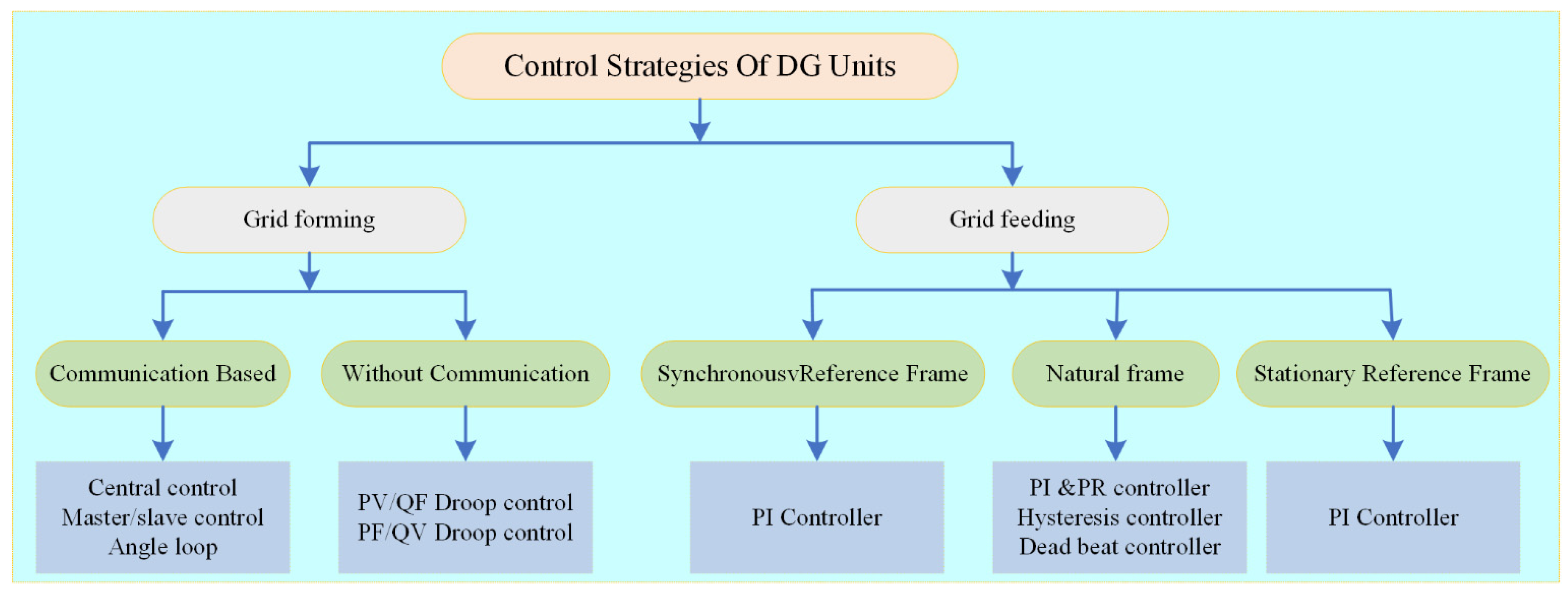
3. Control Strategies for Parallel Operating DGs
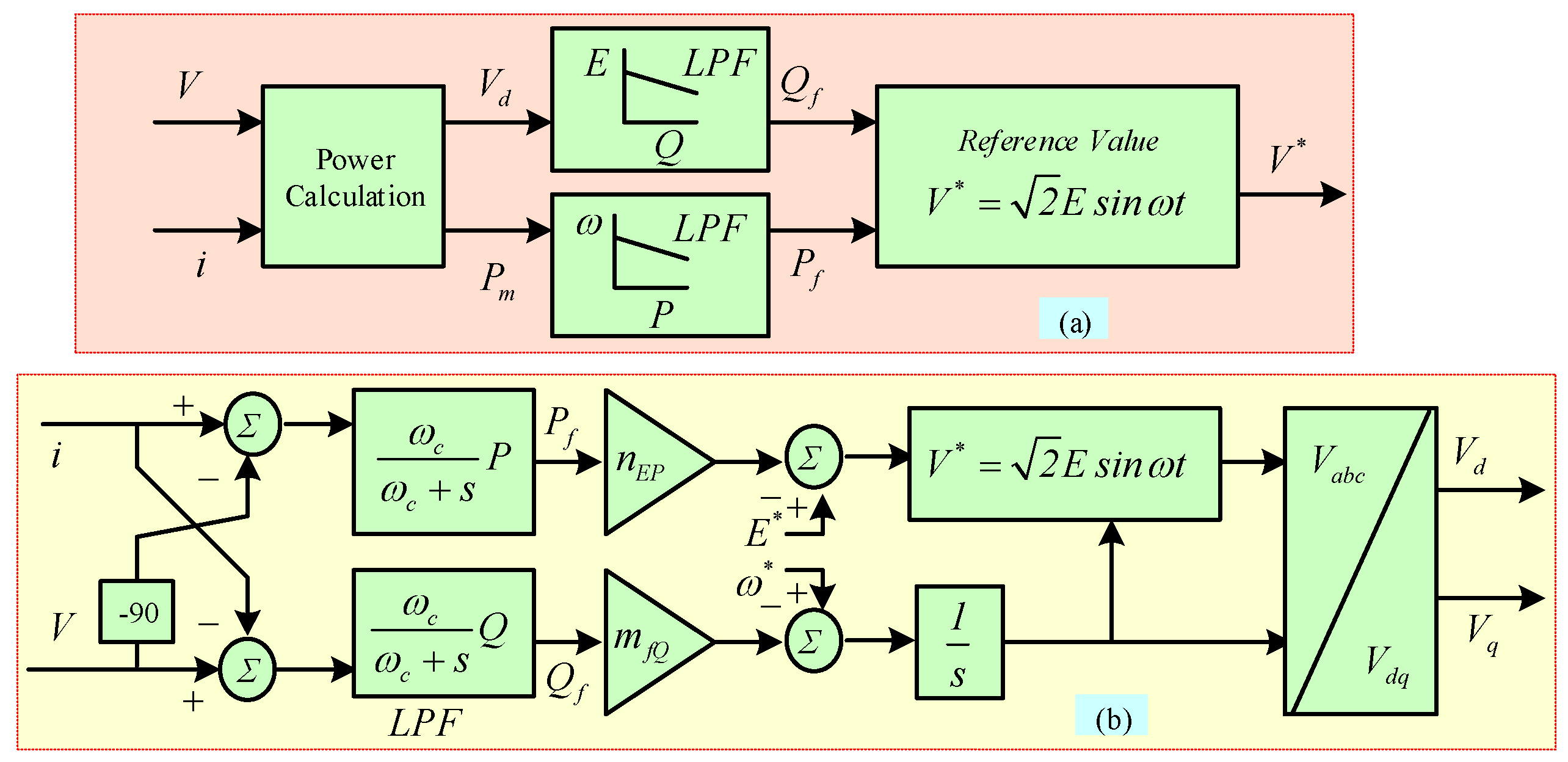
One crucial aspect of microgrid operation is the microgrid energy management system (MEMS), which is the mechanism for microgrid control. It includes the control features that make up a microgrid, which is a self-governing system that may run alone or in conjunction with the main distribution grid and connect and disconnect with ease. The droop control method is commonly used to provide active power sharing, as seen in Figure 4.

3.1. Droop Control

P / f droop control was used by synchronous generators in the transmission system to control speed [35]. In order to precisely distribute power across several generators and limit the amount of mechanical power input, each generating unit monitors and reduces its speed. The generated active power, P , is drooped proportionately to the measured frequency, f , in the traditional P / f droop control method [36]. In converter-based microgrids, measuring active power is simpler than measuring frequency, therefore f is drooping as a function of P . For a certain generating unit i , the P / f and Q / V droops are displayed in Equations (10) and (11).
ω i = ω r e f + K f P i P i r e f
V i = V r e f + K Q , V Q i Q i r e f
Here, K f and K Q , V are the droop constants, and PLL measures the actual frequency of the microgrid, and the measurement value is compared with the nominal frequency [37]. According to the droop control gradient, any frequency mismatch is interpreted as power changes [38]. The droop control method is a communication-free operation and works in plug-and-play integration with good reliability [39].

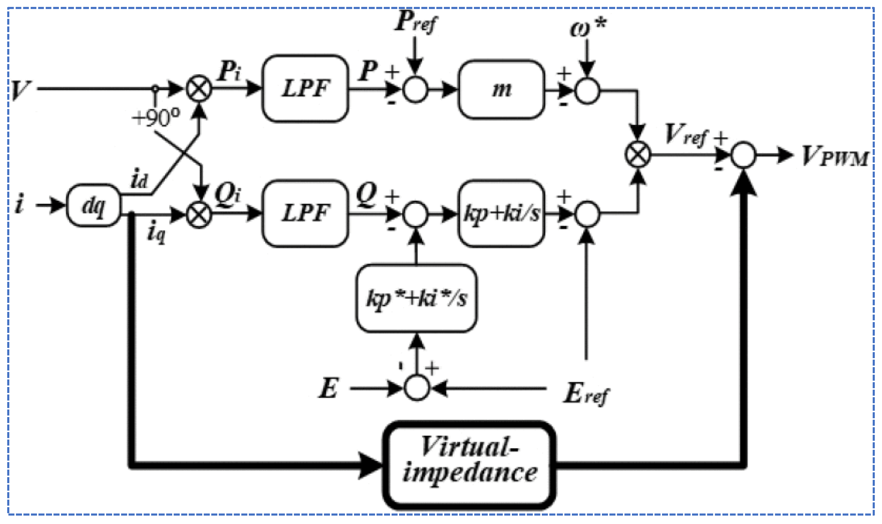
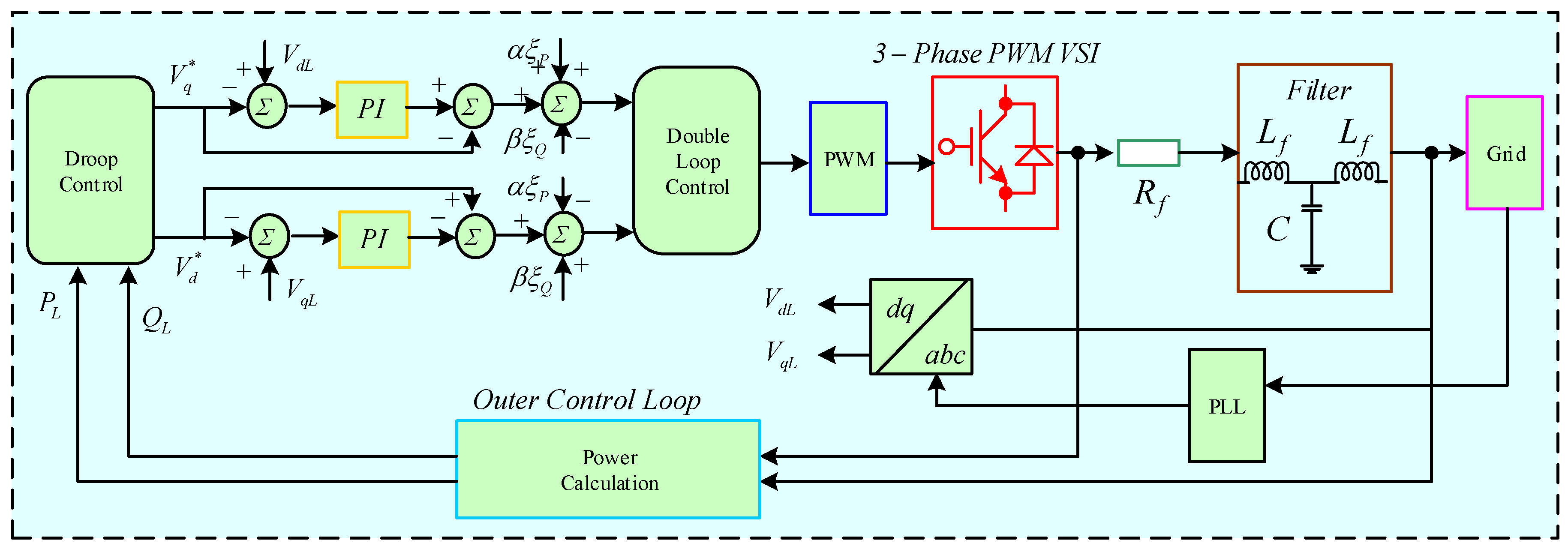
3.2. Virtual Impedance Control

The traditional droop control can be enhanced using a virtual impedance (VI) to get around the coupling problem between active and reactive power. The VI method’s basic idea is to simulate line inductance by deducting a virtual voltage drop from the voltage reference, as shown in Figure 5. Inverters in a microgrid can share active and reactive power more effectively thanks to the virtual impedance (VI) droop management algorithm [40]. As seen in Figure 5, the control designer for VI droop control can alter the effective impedance between the inverter and the load. The current flow in the feeder impedance branch is measured, and the result is multiplied by the suitable impedance that the designer selected. The converter’s voltage reference is changed via the adjusted impedance [41]. The designer duplicates an actual system impedance under steady-state conditions by simulating impedance as a quasi-stationary virtual impedance. Since the real impedances behave differently during the transient period, an increase in the rate of change in current will result in an increase in the voltage drop across the inductor [42]. On the other hand, the voltage quality could deteriorate as a result of adding virtual impedance [43]. To achieve appropriate power sharing, the literature offers yet another sophisticated method based on hierarchical control.

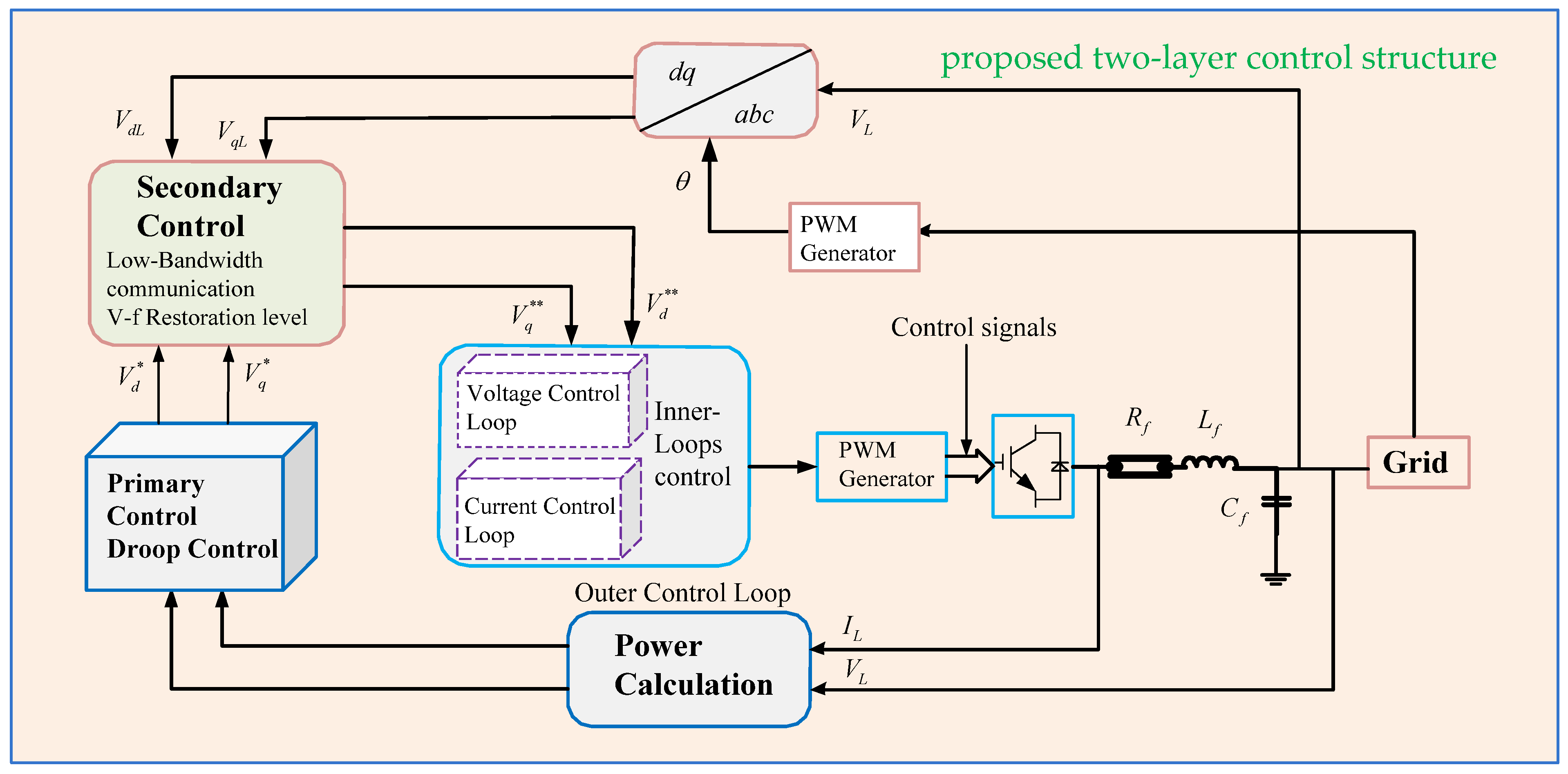
3.3. Hierarchical Control of Microgrid

This article proposes a hierarchical control technique based on two-level energy storage to achieve optimal power flow and adaptable microgrid operation.

3.3.1. Proposed Hierarchical Control Mechanism

A two-level energy storage based hierarchical control approach is developed to guarantee the microgrid operates properly; this helps to maintain system stability, as illustrated in Figure 6. Here, the primary objective is to instantly modify the distributed generators’ reference signal in accordance with the intended results. Additionally, for the grid-tied operation of microgrid, the internal control layers oversee synchronization between the microgrid and the external grid [44]. The next subsection provides a thorough overview of primary and secondary controllers.

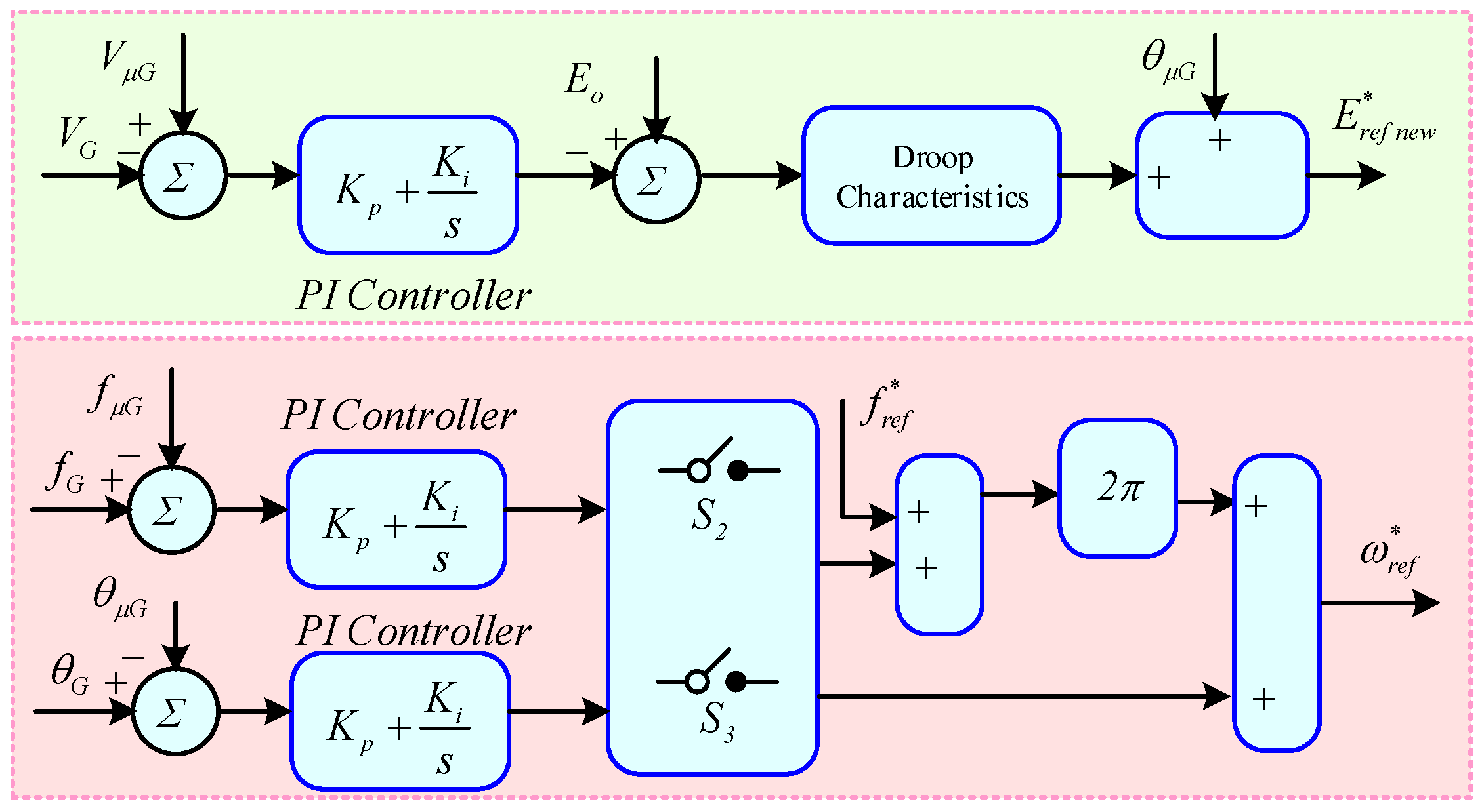
3.3.2. Primary Controller

Inverter-based DGs use droop control to emulate the synchronous generator’s behavior [45]. To comprehend the fundamentals of conventional droop techniques, have a look at the comparable circuit of a VCVSI connected to an AC bus, as illustrated in Figure 7 [46].
Assume that an effective line impedance of Z is created by combining the output impedances of the line and the converter. The following formula is used to compute the complex power delivered to the common AC bus [46].
P = V g E i n v Z c o s θ δ V g 2 Z c o s θ Q = V g E i n v Z s i n θ δ V g 2 Z s i n θ
The preceding equation can be simplified to if the operative line impedance Z θ is assumed to be entirely inductive θ = 90°.
P = V g E i n v Z s i n δ Q = V g E i n v Z c o s δ
E i n v and V g stand for the grid voltage and the inverter output voltage, respectively. The droop control for the system with resistive line impedance is shown in Figure 8. It is possible to express the droop expressions as (14) and (15), respectively.
E i n v * = E i n v + D n E P P m e a s u r e d
ω * = ω + D m f Q Q m e a s u r e d
Here, droop slopes, as defined in (14) and (15), are represented by D n E P and D m f Q , respectively, and the current voltage and frequency are represented by E i n v * and ω * . Thus, as shown in (16) and (17), P m e a s u r e d and Q m e a s u r e d , respectively, indicate the measured active and reactive powers.
D n E P = V m a x V m i n P m a x
D m f Q = ω m a x ω m i n Q m a x
P m e a s u r e d = ω c ω c + s P
Q m e a s u r e d = ω c ω c + s Q

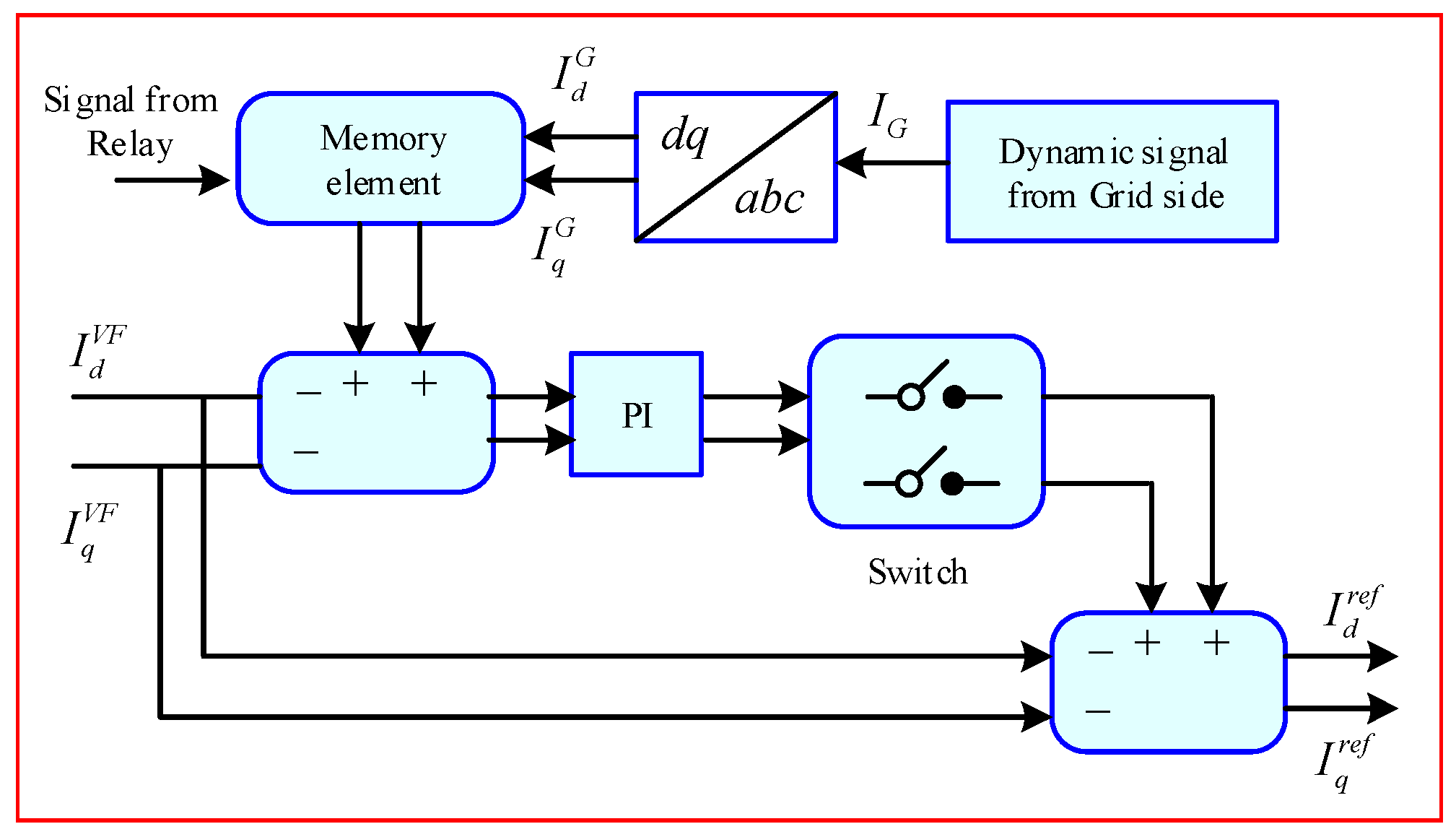
3.3.3. Secondary Controller

The primary internal controller is subordinate to the microgrid central controller at the second level of control. In this case, the primary objective is to modify the distributed generators’ reference points within a microgrid. In grid-connected operations, the internal control also oversees synchronization between the microgrid and utility grid [47]. The droop control may cause a departure from the nominal values in the event of abrupt changes in load. In this context, low-bandwidth communication-based secondary controller is designed to address these issues [48]. This controller regulates variation in voltage and frequency during sudden load variation [49]. Three-phase instantaneous voltages and frequency is converted into synchronously rotating reference frame to make computations easier, as represented in Figure 9.
The direct and quadrature voltages can be calculated as follows:
I q G r e f = K i d c V d c * V d c d t + K p d c V d c * V d c
T e * = K i T ω r * ω r d t + K p T ω r * ω r
Here, V d c * stands for the adjusted voltage references in d q form, and K i d c and K p d c represent the secondary stage controller gains. Because it lessens the steady-state inaccuracy caused by the first stage, this method is more effective than the traditional secondary method. Table 1 provides the controller gain parameters. In this step, the updated voltage references are acquired, as specified in Equations (22) and (23).
V d * * = V d * ω L i q + K p d s e c V d * V d L + K i d s e c V q * V q L d t
V q * * = V q * + K p q s e c V d * V d L + K i d s e c V q * V q L d t

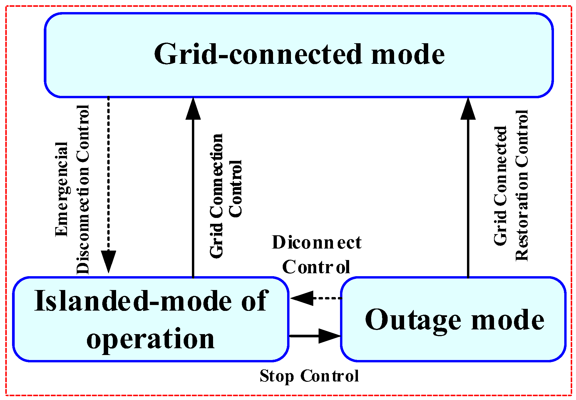
3.3.4. Seamless Mode Transition

For DGs1, the mode transition is mainly discussed [50,51]. Through a load pick-up strategy, the microgrid can restore voltage and frequency for an islanded mode of operation thanks to the grid forming function of the converter [52]. Figure 10 depicts a microgrid’s operating modes. The main grid can quickly and dominantly adjust both frequency and voltage, thus switching from isolated to grid-connected modes—or vice versa—just requires flipping the static switch on or off. As can be seen in Figure 11, the STC continuously checks the state of the microgrid and the utility grid. It has attempted to restart the plant, synchronize the frequency of the system, and supply power to the main grid. At this stage, a few details need to be taken into account, like reactive power balance, transient voltage commutation, balancing power generation, starting sequence, and DGs unit coordination. Lastly, we observed the process of switching a microgrid between grid-connected, islanded, and shutdown modes of operation [53].

3.3.5. Grid-Connected to the Islanded Operating Paradigm

In this shift, two factors are crucial. The primary objective of DG1 for the grid-tied operation of a microgrid is to inject available active power and estimate the active power needed to charge the battery. The first step is the prompt diagnosis of the issue to prevent system deterioration and appropriate adaptation to mode transition. For main grid synchronization, the phase-locked loop (PLL) is employed in this instance. As a result, the following formula can be used to get current references:
I d r e f = I D G 1 I c h B i f S O C B 20 % 0   i f 20 % S O C B 90 % I c h B i f   20 % S O C B 90 %
Here, I c h B and I D G 1 stand for the current that the battery is charging and the output current of the rectified PMSG, respectively. The reactive current in grid-connected mode is zero. Consequently, the utility grid provides the reactive load. The microgrid must cut its connection to the utility and function independently in the event of any abrupt abnormal conditions, such as a fault or a significant frequency variation. When the inputs of the PI controller reach zero, the compensator needs to be disabled in order for the current regulator to operate in the grid-forming mode. Consequently, the following can be used to determine the current references.
I d r e f = K p , d , s e c V d * * V d + K i , d , s e c V d * * V d d t
I q r e f = K p , q , s e c V q * * V q + K i , q , s e c V q * * V q d t
The (25) and (26) can therefore be expressed as,
I d G F = K p , d , s e c V d * * V d + K i , d , s e c V d * * V d d t
I q G F = K p , q , s e c V q * * V q + K i , q , s e c V q * * V q d t
Thus, for an inverter running in grid-forming mode, I d G F and I q G F represent the direct and quadrature current references. On the other hand, for direct and quadrature current regulators, the proportional and integral gains are, respectively, K p , d , s e c , K i , q , s e c , K i , d , s e c and K p , q , s e c .

3.3.6. Islanded Mode to Grid-Tied

During mode transition, a large transient current may be generated. It may result in equipment damage, so specific resynchronization must be performed before the grid-tied operation to enhance a smooth transition of mode transformation [50]. This article proposes a microgrid inverter pre-synchronization control approach based on droop control. The pre-synchronization method is an excellent way to bring microgrid’s synchronizing components under the confines of their prominent grid contemporaries [54]. To synchronize with the utility grid, the instantaneous amplitude of the V and f components in droop control needs to be updated. The new preset reference voltage E n e w * and droop control’s angular frequency ω n e w * are shown in Figure 12.
V G , V μ G , f G , f μ G , θ G , θ μ G are the grid and microgrid side voltages, frequencies, and phase angles, respectively. The synchronizing time is reduced by accurate tuning of gains for PI controllers. As shown in Figure 12, the voltage component’s PI gains can be adjusted individually. Furthermore, because of their mutual influence, the PI gains of the phase angle and frequency components are set together. When the inputs of the PI controllers equal zero, the M G will reconnect to the main grid via the static switch, changing the control strategy simultaneously. An L P F extracts the main grid voltage with the fundamental frequency during synchronization because the main grid voltage frequently contains specific harmonics [55]. In this transition, it is important to note that the droop control outputs in d q reference form serve as the references for the second stage. Disabling the secondary step during the synchronization process is not necessary.

4. Simulation Results and Discussions

The simulations are conducted and verified with MATLAB/Simulink for the proposed system, considering an improved power-sharing strategy. Table 2 and Table 3 provide the parameters with respect to the DGs rating as well as the controller settings. Three instances were examined in this research project in order to examine how faults and variations in load affect the stability of the system and the suggested controller’s ability to share power.

4.1. Proposed Cases

The impact of a three-phase severe fault is analyzed on optimal power sharing and small-signal stability for the proposed hierarchical control mechanism of the WECS-based microgrid. This research addressed three cases to study the impact of the controller on microgrid stability and optimal power flow. The controller’s insight, performance, and system capability during severe faults have been investigated in various conditions. The optimal power-sharing is analyzed for the following cases, which are described as:
  • Case 1: Smooth mode transition
  • Case 2: Sudden load variation
  • Case 3: Fault analysis

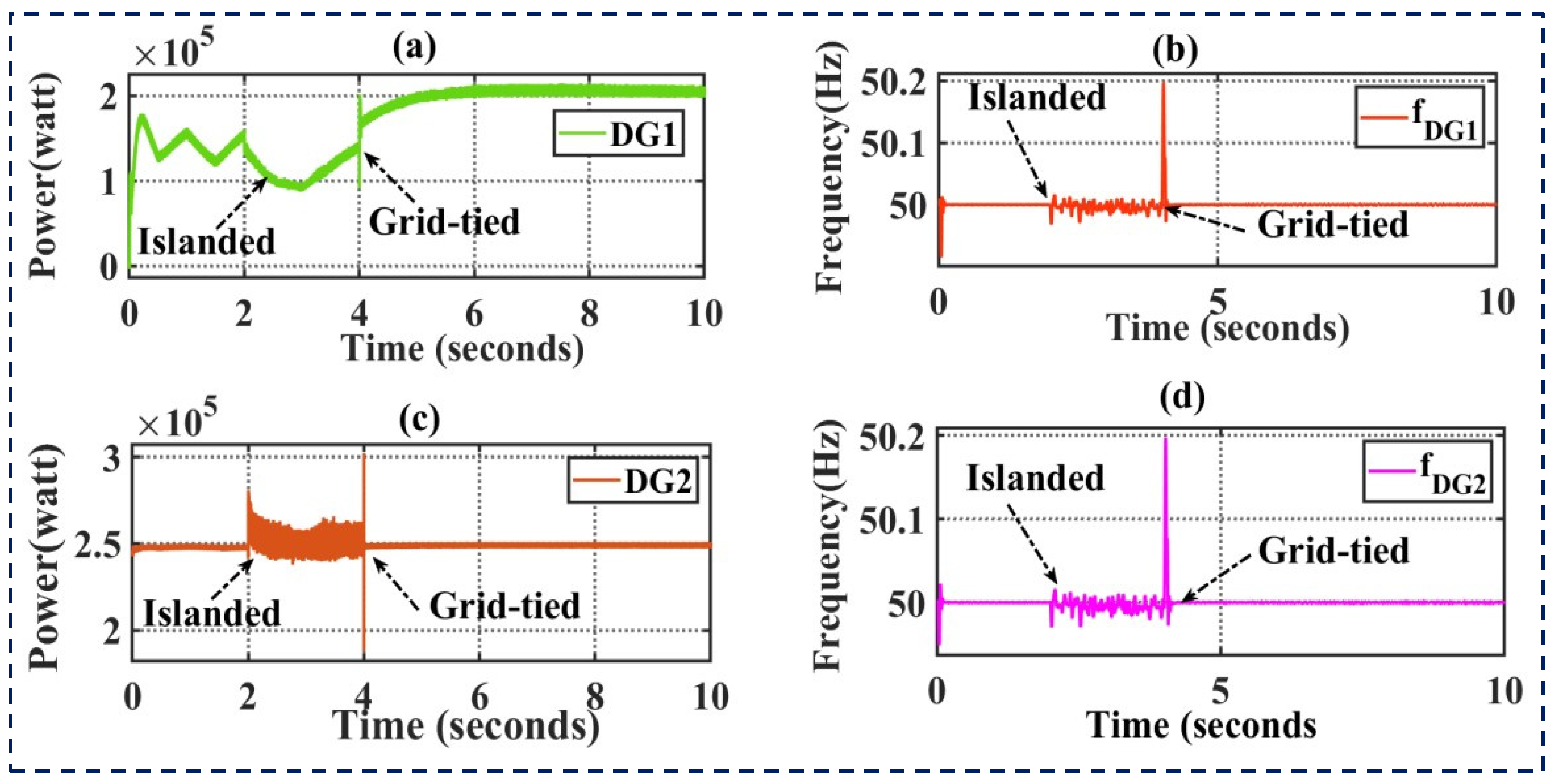
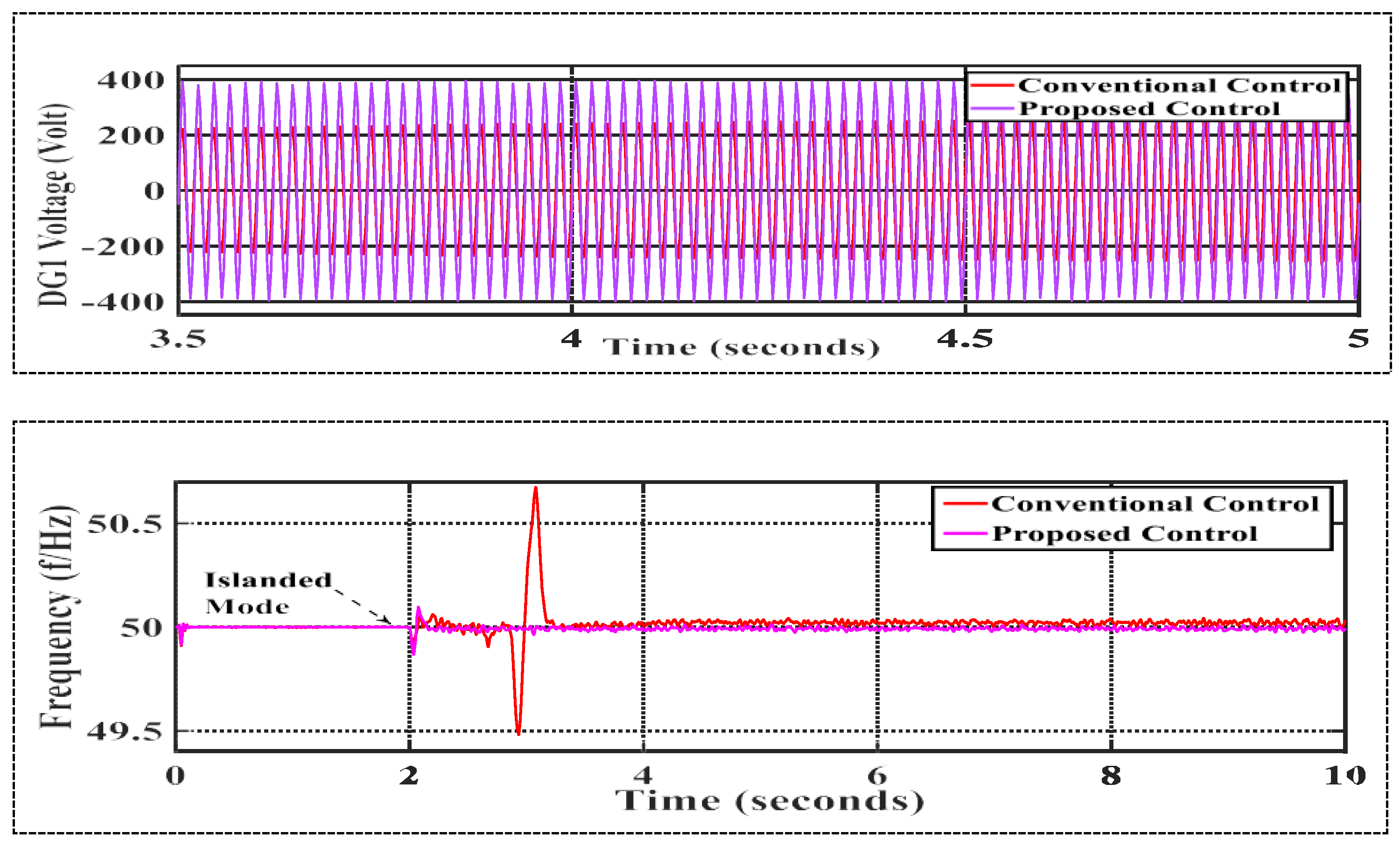
4.2. Seamless Mode Transition

The electric grid outage is planned to happen at t = 2 s. In order to prevent load shedding, the control strategy DG1 switches to the grid-forming technique for the duration of the outage. During this time, microgrid-generated power is adequate to feed the local load. The active power-sharing between DG1 and DG2 at the point of common coupling (PCC) during mode transition is depicted in Figure 13a,c. The frequency response of DG1 and DG2 at the point of common coupling (PCC) during mode transition is displayed in Figure 13b,d. Restoration performance of the secondary controller: using conventional and suggested controller, DG1 power flow is displayed in Figure 14a, voltage response in Figure 14b, current response in Figure 14c, and frequency response in Figure 14d. It is discovered that the suggested method lowers the massive current transient, as illustrated in Figure 14b.

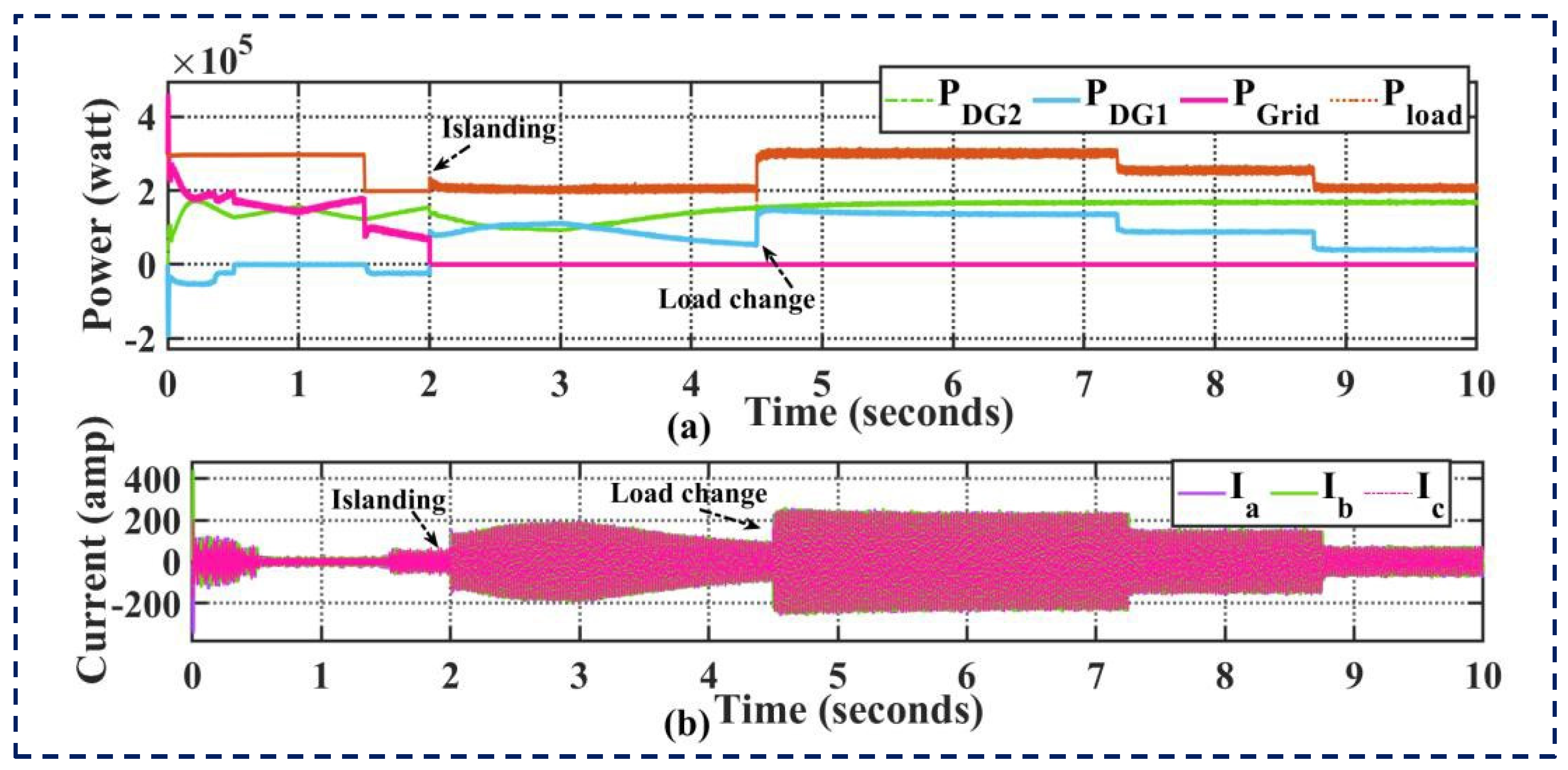
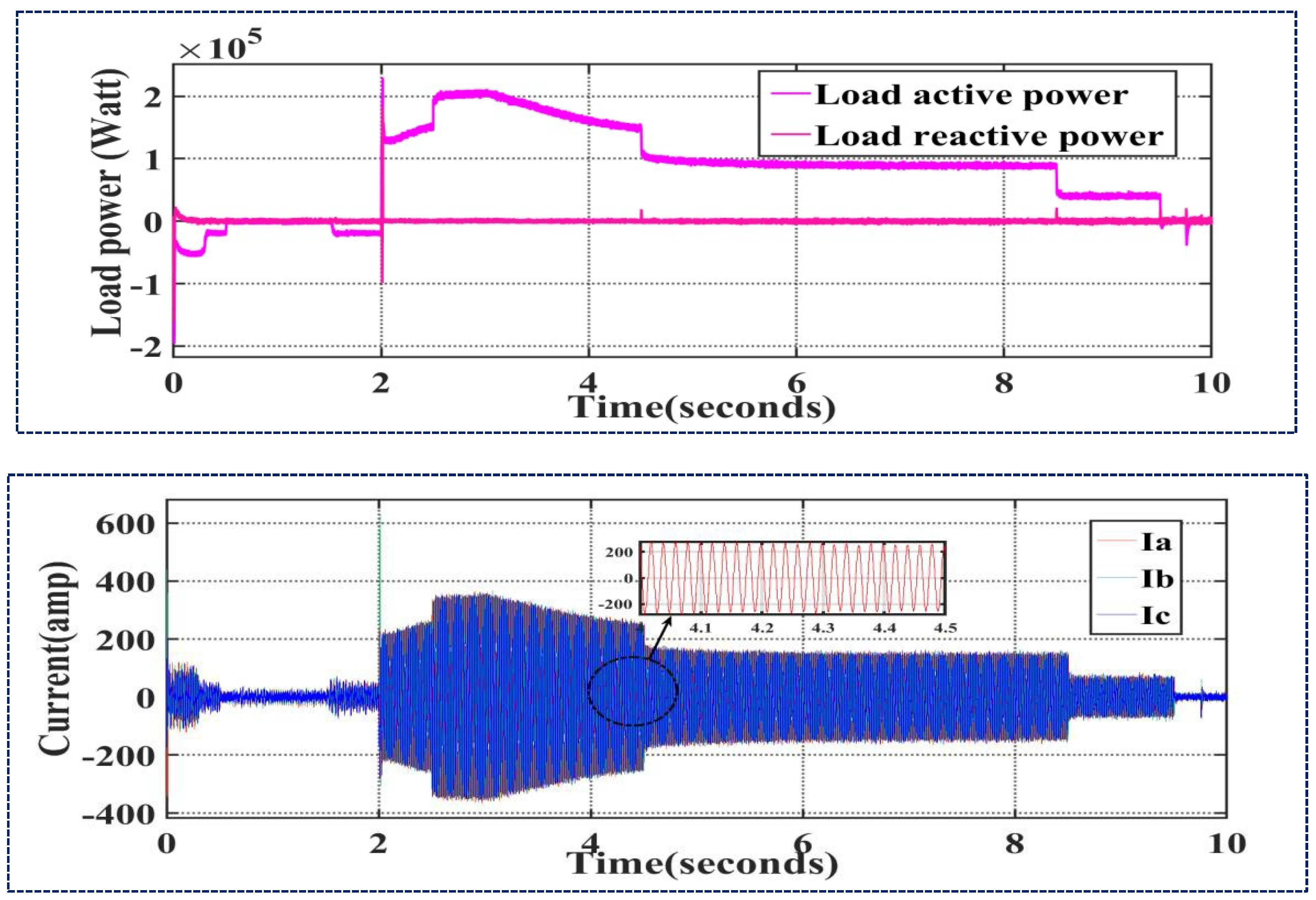
4.3. Effects of Large Changes in Load

Generally speaking, a frequency deviation results from any power variation in the load or generation. Wind turbine generators having constant speed offer a low inertia level, typically between 2 s to 4 s. This is possible because fixed speed wind turbines are directly coupled with the system, and their speed depends on the system frequency. If demand is lower than a generation, frequency increases, and if demand is higher than available power, then frequency decreases. When a mismatch in electrical power is present in the system, the connected generators will have to increase or decrease their speed.
To assess the impact of load variations on the suggested controller, a 50-kW active load is added at t = 2.5 s and subtracted at t = 3 s. Figure 15 shows the restoration’s performance of the proposed controller during balanced load change: (a) Power sharing of DGs, and (b) Load current. The simulation results show smooth power flow during load variation, and overshoots of load current are evidently dampened, as represented in the result. If the load is disconnected from the network, then it leads to an increase in frequency. Therefore, a frequency control mechanism is implemented to mitigate the frequency deviation right after the disturbance of the loads. In the Simulink model, the DG1 and energy storage are assumed to support the frequency. A microgrid’s performance may generally be increased by both a diesel unit and a battery; however, a battery normally has faster control overactive and reactive power than a diesel unit. A total of 50 kW of loads are disconnected at t = 2.75 s; therefore, frequency rises to control it. Similar to wind, DG units can lower their power in order to facilitate frequency responsiveness. A 50 kW load is added at t = 3 s; in this scenario, the frequency starts to decrease, and the DG units cannot support frequency response if they are unable to raise their output. By raising its active power during this time, the battery can sustain the frequency. Figure 16 illustrates how well the suggested controller restored the load with a balanced change in load: Load power (a) and load current (b).

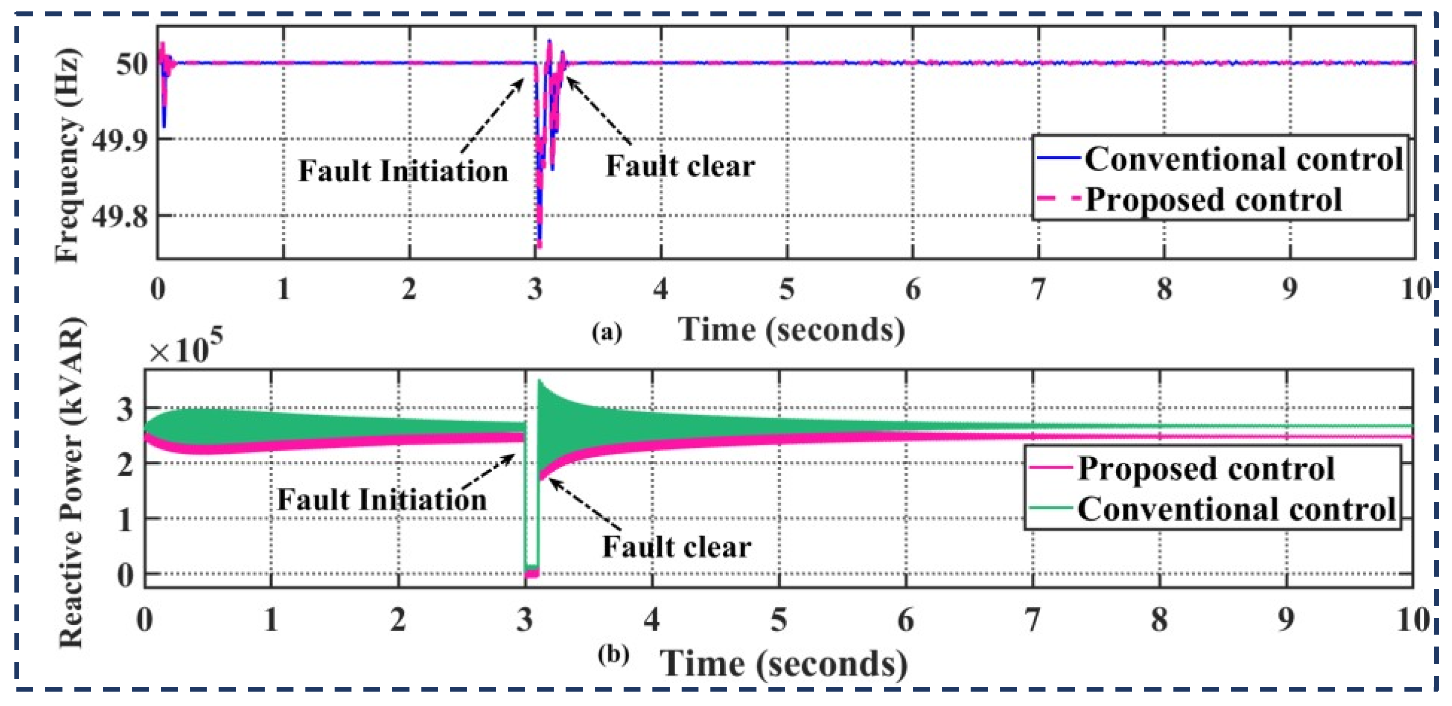
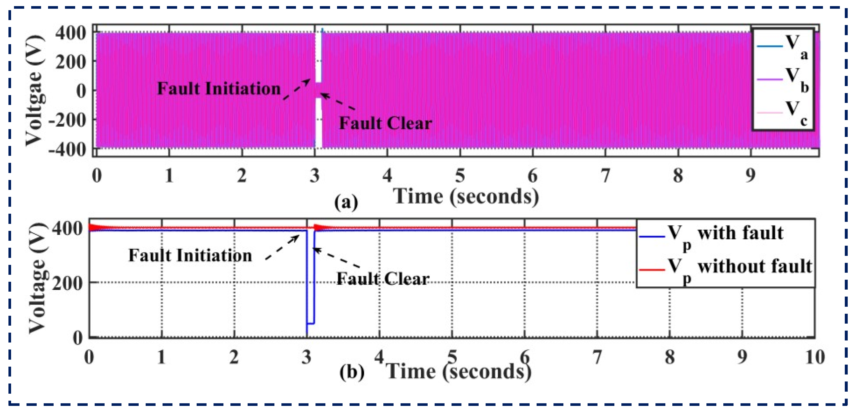
4.4. Performance Analysis during a Three-Phase Fault (Short-Circuit Fault)

One of the most serious defects in the electric system is a short-circuit in a three-phase system. To model the performance of the suggested controller, a three-phase short-circuit fault is applied on the grid side. For a period of two seconds, the problem occurred at t = 3 and was resolved at t = 3.2. The restoration of the secondary stage’s performance during the three-phase fault is depicted in Figure 17 as (a) frequency response and (b) reactive power posture. The suggested controller performance for the restoration during a three-phase fault is depicted in Figure 18: responses in terms of voltage (a) and current (b). The microgrid works in islanded mode and disconnects from the main grid in the event of a fault in the main grid. Additionally, this is known as unintentional islanding. Power deficits in both active and reactive domains could occur during the malfunctioned state. The necessary power and upkeep were provided by the controllers linked to the BESSs. As illustrated in Figure 17, the controller therefore controls the microgrid’s power balance and frequency stability during faulted situations. The ESS supplies the appropriate amount of reactive power to the PCC in order to stabilize the voltage in the event of a short-duration voltage malfunction in the main grid. The circuit breakers in Detroit’s microgrid instantly cut it off from the main grid and put it in island mode in the event of a serious outage in the main grid or power quality.

5. Conclusions

This study offers a strong hierarchical control framework that microgrids can use to achieve ideal power flow and smooth transitions between islanded and grid-tied modes of operation. Here, each of the two DGs has a distinct goal. The DG1 unit, which is coupled to the BESS, regulates frequency stability while the system is in the islanded mode of operation. In contrast, DG2 is operated with grid-integrated adaptive control to avoid power imbalance during load changes or excess power generation. Moreover, this study also focuses on optimal power sharing during load variation and abnormal conditions like faults. The proposed secondary controller enables the microgrid system to operate in a stable region. The outcome analysis demonstrates how hierarchical control systems can improve the system’s transient stability during a three-phase fault. The simulation results demonstrate how well the suggested secondary controller restores voltage and frequency irregularities brought on by the primary control. It is concluded that the simulation results demonstrate the effectiveness of the suggested methodology, both for the two-mode transition formulations that are described and for rapid changes in load that compare favorably to the current control method.
By integrating hybrid renewable integrated systems with real-time climate controls, the impact of the increased energy demand can be managed. A more appropriate approach to this problem would be to identify specific study sites where these resources are abundant. Finding specific study sites where these resources are abundant would be a more appropriate approach to this problem. Considering the different modes of operation of hybrid systems, an analysis of the techno-economic behavior of grid-connected systems may be interesting. Achieving sustainable energy for both communities in the country would be an entirely new venture and probably lead to a new era of research. Thus, current work opens new scopes of study, optimizing multi-objective research from a multidisciplinary perspective.

Funding

The author extends their appreciation to the Deanship of Scientific Research at King Khalid University, Saudi Arabia for funding this work through the Research Group Program under Grant No: RGP 2/55/45.

Institutional Review Board Statement

Not applicable.

Informed Consent Statement

Not applicable.

Data Availability Statement

Data are contained within the article.

Conflicts of Interest

The author declares that they have no known competing financial interests or personal relationships that could have appeared to influence the work reported in this paper.

References

  1. Guerrero, J.M.; Kandari, R. Microgrids Modeling, Control, and Applications, 1st ed.; Academic Press: Cambridge, MA, USA, 2021; p. 268. ISBN 9780323854634. [Google Scholar]
  2. Farhangi, H.; Joos, G. Microgrid Planning and Design: A Concise Guide; Wiley-IEEE Press: Hoboken, NJ, USA, 2019; p. 256. ISBN 9781119453505. [Google Scholar]
  3. Ren, L.; Zhang, P. Generalized Microgrid Power Flow. IEEE Trans. Smart Grid 2018, 9, 3911–3913. [Google Scholar] [CrossRef]
  4. Agundis-Tinajero, G.; Segundo-Ramírez, J.; Visairo-Cruz, N.; Savaghebi, M.; Guerrero, J.M.; Barocio, E. Power flow modeling of islanded AC microgrids with hierarchical control. Int. J. Electr. Power Energy Syst. 2019, 105, 28–36. [Google Scholar] [CrossRef]
  5. Keerthana, M.; Manoharan, P.S.; Ravi, A. Design of Control Strategy for Battery-Supercapacitor Hybrid Storage System. In Proceedings of the 2022 7th International Conference on Communication and Electronics Systems (ICCES), Coimbatore, India, 22–24 June 2022; pp. 798–803. [Google Scholar] [CrossRef]
  6. Singh, P.; Lather, J.S. Variable structure control for dynamic powersharing and voltage regulation of DC microgrid with a hybrid energy storage system. Int. Trans. Electr. Energy Syst. 2020, 30, e12510. [Google Scholar] [CrossRef]
  7. Hoang, K.D.; Lee, H.-H. Accurate Power Sharing with Balanced Battery State of Charge in Distributed DC Microgrid. IEEE Trans. Ind. Electron. 2019, 66, 1883–1893. [Google Scholar] [CrossRef]
  8. Kamal, T.; Hassan, S.Z.; Espinosa-Trujillo, M.J.; Li, H.; Flota, V. An optimal power sharing and power control strategy of photovoltaic/fuel cell/ultra-capacitor hybrid power system. J. Renew. Sustain. Energy 2016, 8, 035301. [Google Scholar] [CrossRef]
  9. Jiang, W.; Zhang, L.; Zhao, H.; Huang, H.; Hu, R. Research on power sharing strategy of hybrid energy storage system in photovoltaic power station based on multi-objective optimization. IET Renew. Power Gener. 2016, 10, 575–583. [Google Scholar] [CrossRef]
  10. Mahmud, M.A.; Hossain, M.J.; Pota, H.R.; Oo, A.M.T. Robust Nonlinear Distributed Controller Design for Active and Reactive Power Sharing in Islanded Microgrids. IEEE Trans. Energy Convers. 2014, 29, 893–903. [Google Scholar] [CrossRef]
  11. Shafiee, Q.; Guerrero, J.M.; Vasquez, J.C. Distributed Secondary Control for Islanded Microgrids—A Novel Approach. IEEE Trans. Power Electron. 2014, 29, 1018–1031. [Google Scholar] [CrossRef]
  12. Lu, X.; Guerrero, J.M.; Sun, K.; Vasquez, J.C.; Teodorescu, R.; Huang, L. Hierarchical Control of Parallel AC-DC Converter Interfaces for Hybrid Microgrids. IEEE Trans. Smart Grid 2014, 5, 683–692. [Google Scholar] [CrossRef]
  13. Kumar, A.; Bhadu, M. Wide-area damping control system for large wind generation with multiple operational uncertainty. Electr. Power Syst. Res. 2022, 213, 108755. [Google Scholar] [CrossRef]
  14. Baghaee, H.R.; Mirsalim, M.; Gharehpetian, G.B. Power Calculation Using RBF Neural Networks to Improve Power Sharing of Hierarchical Control Scheme in Multi-DER Microgrids. IEEE J. Emerg. Sel. Top. Power Electron. 2016, 4, 1217–1225. [Google Scholar] [CrossRef]
  15. Wu, D.; Tang, F.; Dragicevic, T.; Vasquez, J.C.; Guerrero, J.M. Autonomous Active Power Control for Islanded AC Microgrids with Photovoltaic Generation and Energy Storage System. IEEE Trans. Energy Convers. 2014, 29, 882–892. [Google Scholar] [CrossRef]
  16. Han, H.; Liu, Y.; Sun, Y.; Su, M.; Guerrero, J.M. An Improved Droop Control Strategy for Reactive Power Sharing in Islanded Microgrid. IEEE Trans. Power Electron. 2015, 30, 3133–3141. [Google Scholar] [CrossRef]
  17. Zhao, Z.; Yang, P.; Guerrero, J.M.; Xu, Z.; Green, T.C. Multiple-Time-Scales Hierarchical Frequency Stability Control Strategy of Medium-Voltage Isolated Microgrid. IEEE Trans. Power Electron. 2016, 31, 5974–5991. [Google Scholar] [CrossRef]
  18. Kumar, A.; Bhadu, M.; Arabi, A.I.A.; Kamangar, S.; Bhutto, J.K.; Ali, M.A.; Kumar, S. Optimized robust control for improving frequency response of delay dependent AC microgrid with uncertainties. Electr. Power Syst. Res. 2024, 229, 110138. [Google Scholar] [CrossRef]
  19. Han, Y.; Shen, P.; Zhao, X.; Guerrero, J.M. Control Strategies for Islanded Microgrid Using Enhanced Hierarchical Control Structure with Multiple Current-Loop Damping Schemes. IEEE Trans. Smart Grid 2017, 8, 1139–1153. [Google Scholar] [CrossRef]
  20. Guerrero, J.M.; Matas, J.; de Vicuna, L.G.; Castilla, M.; Miret, J. Decentralized Control for Parallel Operation of Distributed Generation Inverters Using Resistive Output Impedance. IEEE Trans. Ind. Electron. 2007, 54, 994–1004. [Google Scholar] [CrossRef]
  21. Ding, B.; Li, Z.; Li, Z.; Xue, Y.; Chang, X.; Su, J.; Jin, X.; Sun, H. A CCP-based distributed cooperative operation strategy for multi-agent energy systems integrated with wind, solar, and buildings. Appl. Energy 2024, 365, 123275. [Google Scholar] [CrossRef]
  22. Li, Z.; Su, S.; Jin, X.; Xia, M.; Chen, Q.; Yamashita, K. Stochastic and Distributed Optimal Energy Management of Active Distribution Networks within Integrated Office Buildings. CSEE J. Power Energy Syst. 2024, 10, 504–517. [Google Scholar] [CrossRef]
  23. Taher, A.M.; Hasanien, H.M.; Ginidi, A.R.; Taha, A.T.M. Hierarchical Model Predictive Control for Performance Enhancement of Autonomous Microgrids. Ain Shams Eng. J. 2021, 12, 1867–1881. [Google Scholar] [CrossRef]
  24. IEEE 2030.7-2017; IEEE Standard for the Specification of Microgrid Controllers. IEEE: Piscataway, NJ, USA, 2018; pp. 1–43. [CrossRef]
  25. La Bella, A.; Cominesi, S.R.; Sandroni, C.; Scattolini, R. Hierarchical Predictive Control of Microgrids in Islanded Operation. IEEE Trans. Autom. Sci. Eng. 2017, 14, 536–546. [Google Scholar] [CrossRef]
  26. Vasquez, J.C.; Guerrero, J.M.; Miret, J.; Castilla, M.; de Vicuña, L.G. Hierarchical Control of Intelligent Microgrids. IEEE Ind. Electron. Mag. 2010, 4, 23–29. [Google Scholar] [CrossRef]
  27. Li, Y.W.; Kao, C.-N. An Accurate Power Control Strategy for Power-Electronics-Interfaced Distributed Generation Units Operating in a Low-Voltage Multibus Microgrid. IEEE Trans. Power Electron. 2009, 24, 2977–2988. [Google Scholar] [CrossRef]
  28. Micallef, A.; Apap, M.; Staines, C.S.; Zapata, J.M.G. Secondary control for reactive power sharing and voltage amplitude restoration in droop-controlled islanded microgrids. In Proceedings of the 2012 3rd IEEE International Symposium on Power Electronics for Distributed Generation Systems (PEDG), Aalborg, Denmark, 25–28 June 2012; pp. 492–498. [Google Scholar] [CrossRef]
  29. De Brabandere, K.; Bolsens, B.; Van den Keybus, J.; Woyte, A.; Driesen, J.; Belmans, R. A Voltage and Frequency Droop Control Method for Parallel Inverters. IEEE Trans. Power Electron. 2007, 22, 1107–1115. [Google Scholar] [CrossRef]
  30. Jahanpour-Dehkordi, M.; Vaez-Zadeh, S.; Mohammadi, J. Development of a Combined Control System to Improve the Performance of a PMSG-Based Wind Energy Conversion System Under Normal and Grid Fault Conditions. IEEE Trans. Energy Convers. 2019, 34, 1287–1295. [Google Scholar] [CrossRef]
  31. Liao, K.; Pang, B.; Yang, J.; He, Z. Output Current Quality Improvement for VSC with Capability of Compensating Voltage Harmonics. IEEE Trans. Ind. Electron. 2024, 71, 9087–9097. [Google Scholar] [CrossRef]
  32. Li, S.; Haskew, T.A.; Swatloski, R.P.; Gathings, W. Optimal and Direct-Current Vector Control of Direct-Driven PMSG Wind Turbines. IEEE Trans. Ind. Electron. 2012, 27, 2325–2337. [Google Scholar] [CrossRef]
  33. Engler, A.; Soultanis, N. Droop control in LV-grids. In Proceedings of the 2005 International Conference on Future Power Systems, Amsterdam, The Netherlands, 18 November 2005; pp. 1–6. [Google Scholar] [CrossRef]
  34. Bidram, A.; Davoudi, A. Hierarchical Structure of Microgrids Control System. IEEE Trans. Smart Grid 2012, 3, 1963–1976. [Google Scholar] [CrossRef]
  35. Fan, B.; Li, Q.; Wang, W.; Yao, G.; Ma, H.; Zeng, X.-J.; Guerrero, J.M. A Novel Droop Control Strategy of Reactive Power Sharing Based on Adaptive Virtual Impedance in Microgrids. IEEE Trans. Ind. Electron. 2022, 69, 11335–11347. [Google Scholar] [CrossRef]
  36. Ling, Y.; Li, Y.; Yang, Z.; Xiang, J. A Dispatchable Droop Control Method for Distributed Generators in Islanded AC Microgrids. IEEE Trans. Ind. Electron. 2021, 68, 8356–8366. [Google Scholar] [CrossRef]
  37. Sevostyanov, N.A.; Gorbunov, R.L. Control Strategy to Mitigate Voltage Ripples in Droop-Controlled DC Microgrids. IEEE Trans. Ind. Electron. 2023, 38, 15377–15389. [Google Scholar] [CrossRef]
  38. Alghamdi, B.; Cañizares, C.A. Frequency Regulation in Isolated Microgrids through Optimal Droop Gain and Voltage Control. IEEE Trans. Smart Grid 2021, 12, 988–998. [Google Scholar] [CrossRef]
  39. Keyvani-Boroujeni, B.; Fani, B.; Shahgholian, G.; Alhelou, H.H. Virtual Impedance-Based Droop Control Scheme to Avoid Power Quality and Stability Problems in VSI-Dominated Microgrids. IEEE Access 2021, 9, 144999–145011. [Google Scholar] [CrossRef]
  40. Sharma, S.; Iyer, V.M.; Bhattacharya, S. An Optimized Nonlinear Droop Control Method Using Load Profile for DC Microgrids. IEEE J. Emerg. Sel. Top. Ind. Electron. 2023, 4, 3–13. [Google Scholar] [CrossRef]
  41. Perez, F.; Damm, G.; Verrelli, C.M.; Ribeiro, P.F. Adaptive Virtual Inertia Control for Stable Microgrid Operation Including Ancillary Services Support. IEEE Trans. Control Syst. Technol. 2023, 31, 1552–1564. [Google Scholar] [CrossRef]
  42. Wang, K.; Yuan, X. Stability Analysis of the Virtual Inductance for LCL Filtered Droop-Controlled Grid-Connected Inverters. IEEE J. Emerg. Sel. Top. Power Electron. 2022, 10, 2685–2698. [Google Scholar] [CrossRef]
  43. Cao, W.; Han, M.; Zhang, X.; Guan, Y.; Guerrero, J.M.; Vasquez, J.C. An Integrated Synchronization and Control Strategy for Parallel-Operated Inverters Based on V–I Droop Characteristics. IEEE Trans. Ind. Electron. 2022, 37, 5373–5384. [Google Scholar] [CrossRef]
  44. Imran, R.M.; Wang, S. Enhanced Two-Stage Hierarchical Control for a Dual Mode WECS-Based Microgrid. Energies 2018, 11, 1270. [Google Scholar] [CrossRef]
  45. Ahmed, M.; Meegahapola, L.; Vahidnia, A.; Datta, M. Adaptive Virtual Impedance Controller for Parallel and Radial Microgrids with Varying X/R Ratios. IEEE Trans. Sustain. Energy 2022, 13, 830–843. [Google Scholar] [CrossRef]
  46. Fan, L. Control and Dynamics in Power Systems and Microgrids; CRC Press: Boca Raton, FL, USA, 2017. [Google Scholar]
  47. Li, X.; Wen, C.; Chen, C.; Xu, Q. Adaptive Resilient Secondary Control for Microgrids with Communication Faults. IEEE Trans. Cybern. 2022, 52, 8493–8503. [Google Scholar] [CrossRef] [PubMed]
  48. Adibi, M.; van der Woude, J. Secondary Frequency Control of Microgrids: An Online Reinforcement Learning Approach. IEEE Trans. Autom. Control 2022, 67, 4824–4831. [Google Scholar] [CrossRef]
  49. Habibi, S.I.; Sheikhi, M.A.; Khalili, T.; Abadi, S.A.G.K.; Bidram, A.; Guerrero, J.M. Multiagent-Based Nonlinear Generalized Minimum Variance Control for Islanded AC Microgrids. IEEE Trans. Power Syst. 2024, 39, 316–328. [Google Scholar] [CrossRef]
  50. Talapur, G.G.; Suryawanshi, H.M.; Xu, L.; Shitole, A.B. A Reliable Microgrid with Seamless Transition Between Grid Connected and Islanded Mode for Residential Community with Enhanced Power Quality. IEEE Trans. Ind. Appl. 2018, 54, 5246–5255. [Google Scholar] [CrossRef]
  51. Agyekum, E.B.; Nutakor, C. Feasibility study and economic analysis of standalone hybrid energy system for southern Ghana. Sustain. Energy Technol. Assess. 2020, 39, 100695. [Google Scholar]
  52. D’silva, S.; Shadmand, M.; Bayhan, S.; Abu-Rub, H. Towards Grid of Microgrids: Seamless Transition between Grid-Connected and Islanded Modes of Operation. IEEE Open J. Ind. Electron. Soc. 2020, 1, 66–81. [Google Scholar] [CrossRef]
  53. Das, S.; Singh, B. Self-Synchronizing Control Enabling Disruption-Free Operation and Seamless Mode Transitions in Wind–Solar Based Hybrid AC/DC Microgrid. IEEE Trans. Ind. Appl. 2023, 59, 4797–4807. [Google Scholar] [CrossRef]
  54. Gao, M.; Chen, M.; Zhao, B.; Li, B.; Qian, Z. Design of Control System for Smooth Mode-Transfer of Grid-Tied Mode and Islanding Mode in Microgrid. IEEE Trans. Ind. Electron. 2020, 35, 6419–6435. [Google Scholar] [CrossRef]
  55. de Araujo Ribeiro, R.L.; de Oliveira Alves Rocha, T.; de Sousa, R.M.; dos Santos, E.C.; Lima, A.M.N. A Robust DC-Link Voltage Control Strategy to Enhance the Performance of Shunt Active Power Filters without Harmonic Detection Schemes. IEEE Trans. Ind. Electron. 2015, 62, 803–813. [Google Scholar] [CrossRef]
Figure 1. Layout of system under study.
Sustainability 16 05872 g001
Figure 2. Control configuration of DGs 1.
Sustainability 16 05872 g002
Figure 3. Configuration control scheme for PMSG-based DG2.
Sustainability 16 05872 g003
Figure 4. Various control strategies for DG units.
Sustainability 16 05872 g004
Figure 5. Virtual impedance-driven droop management.
Sustainability 16 05872 g005
Figure 6. A microgrid’s proposed two-layer control structure.
Sustainability 16 05872 g006
Figure 7. Diagram in single lines showing a DG unit attached to the PCC bus.
Sustainability 16 05872 g007
Figure 8. Utilized droop control strategy (a) power measurement, (b) droop controller.
Sustainability 16 05872 g008
Figure 9. Secondary control strategy.
Sustainability 16 05872 g009
Figure 10. Operation modes of a microgrid.
Sustainability 16 05872 g010
Figure 11. Transition control for the unplanned outage.
Sustainability 16 05872 g011
Figure 12. Real power and reactive power compensator with pre-synchronization.
Sustainability 16 05872 g012
Figure 13. Seamless transition: (a) Power sharing of DG1 (b) Frequency response of DG1 (c) Power-sharing of DG2 (d) Frequency response of DG2.
Sustainability 16 05872 g013
Figure 14. Restoration’s performance of secondary controller (a) DG1 power flow (b) Voltage response of DG1 (c) Current response of DG1 (d) Frequency response of DG1.
Sustainability 16 05872 g014aSustainability 16 05872 g014b
Figure 15. Restoration’s performance of proposed controller during balanced load change: (a) Power sharing of DGs (b) Load current.
Sustainability 16 05872 g015
Figure 16. The suggested controller’s performance restoration during a balanced load change is measured by two factors: load power and load current.
Sustainability 16 05872 g016
Figure 17. Restoration’s performance of secondary stage during 3-phase fault: (a) Frequency response (b) Reactive power posture.
Sustainability 16 05872 g017
Figure 18. Restoration’s performance of proposed controller during 3-phase fault: (a) Voltage response, (b) Current response.
Sustainability 16 05872 g018
Table 1. Controller gain parameters.
SymbolValue
ω c 12 rad/s
D n E P 0.0007 V/W
D m F Q 0.0006 rad/s/VAR
K d   s e c p 2.4
K d   s e c i 10
K 1.8
V * 390 V
Table 2. Sizing parameters of the system under study.
System Sizing
EquipmentValues
DG1260 kVA
DG2200 kVA
Battery350 kWh
System Parameter
Grid voltage (L-L)480 V
Grid frequency50 Hz
DG1 LC filter4 mH, 55 F
DG2 LC filter4 mH, 55 F
Table 3. Control parameters of the case study microgrid.
ParametersKpKi
DG1RSC-Current controller -d axis3.2539
RSC-Current controller -q axis1.70.66
RSC-Voltage controller -d axis0.8448
RSC-Voltage controller -q axis0.6774.4
Boost DC current controller0.5713.7
Buck/Boost DC current controller4.661
DG2DG2-GSC-Current controller -q axis5.182
DG2-GSC-DC voltage controller10.662
DG2-Chopper voltage controller2175
DG2-MSC-Current controller -d axis0.35.9
DG2-MSC-Current controller -q axis3.811
DG2-GSC-Current controller -d axis3.811
Pre
synchronization
control-Voltage component0.213.9
control-Frequency component42.3
control-Phase angle component118.5
Disclaimer/Publisher’s Note: The statements, opinions and data contained in all publications are solely those of the individual author(s) and contributor(s) and not of MDPI and/or the editor(s). MDPI and/or the editor(s) disclaim responsibility for any injury to people or property resulting from any ideas, methods, instructions or products referred to in the content.

