Article

Numerical Analysis on Heat Collecting Performance of Novel Corrugated Flat Plate Solar Collector Using Nanofluids

1
School of Automotive Studies, Tongji University, Shanghai 200804, China
2
Clean Energy Automotive Engineering Center, Tongji University, Shanghai 200804, China
3
State Key Laboratory of Automotive Simulation and Control, Jilin University, Changchun 130022, China
4
School of Electrical Engineering and Automation, Harbin Institute of Technology, Harbin 150001, China
*
Authors to whom correspondence should be addressed.
Sustainability 2024, 16(14), 5924; https://doi.org/10.3390/su16145924
Submission received: 11 June 2024 / Revised: 1 July 2024 / Accepted: 8 July 2024 / Published: 11 July 2024
(This article belongs to the Section Energy Sustainability)

Abstract

:
To improve the heat collection performance of flat plate solar collectors, a corrugated flat plate solar collector (CFPSC) with a triangular collector tube was first innovatively designed in this paper. The effect of various nanofluids that are used as working fluid on the heat collection performance of CFPSC was comprehensively analyzed based on the heat collection characteristics test system and numerical simulation model. The results indicate that when CuO and Al2O3 were used as nanoparticles, the heat collection stabilization time of the nanofluids for which ethylene glycol (EG) was used as the base fluid was 12.4~28.6% longer than that of the nanofluids for which water was used as the base fluid. Moreover, when the base fluid was EG, the temperature difference of CuO-EG nanofluid under different radiation intensities was about 5.8~19.2% higher than that of water. Furthermore, the heat collection performance of CuO nanofluids and Al2O3 nanofluids was superior to TiN nanofluids. Specifically, the heat collection of CuO-EG nanofluid was 2.9~4% higher than that of TiN-EG nanofluid at different radiation intensities. Therefore, using nanofluids as a working medium and designing a flat plate solar collector with triangular collector tubes can significantly improve the collector performance.

1. Introduction

Green and low-carbon development has become the overarching trend in global energy evolution [1,2]. Solar energy is a promising sustainable alternative energy because of its abundant resources and no pollutant emission [3,4]. It has become a hot technology for energy saving, low-carbon, and sustainable development, and has been widely used in heat utilization [5,6]. The FPSC is one of the most common technologies for utilizing solar energy [7,8,9]. To improve the heat collection efficiency of the FPSC, the optimization of its structure [10,11,12] and exploration of the heat transfer media [13,14] inside the FPSC are two main research directions.
As an important factor affecting the heal collection performance of solar collectors, nanofluids have been widely used in FPSC due to their good heat transfer characteristics [15,16,17,18]. In fact, nanofluids with nanoparticles directly absorb the incident solar radiation directly, making nanofluids more efficient than water in terms of thermal efficiency [19,20]. Ali [21] and Rehman et al. [22]. studied the influence of heat transfer of nanofluids in heat exchangers by partial differential equations. Choi et al. [23] from Argonne Laboratory proposed the concept of nanofluid in 1995. Researchers used nanofluid as a working fluid and studied the influence of different working fluids on heat collection performance, which provided creative solutions for improving the heat collection efficiency of flat plate solar collectors. Daharmakkan et al. [24] described the advantages of nanofluids in terms of absorption of solar radiation, thermal conductivity, and convective heat transfer performance, which provides reliable proof for nanofluids as working fluids. Deshmukh et al. [25] studied the thermophysical properties of TiN nanofluids with different mass fractions, finding that as the mass fraction increases, the surface tension, kinematic viscosity, and thermal conductivity increase by 0.6%, 4.6%, and 5.9%, respectively. To improve the turbulence of nanoparticles in the base fluid, Ehsan et al. [26] increased the magnetic field in the experiment system and chose Mn-ZnFe2O4/Water nanofluid as working fluid, finding that the average Nusselt number of the working fluid and thermal efficiency of a single-ended all-glass evacuated tube solar collector (SEETSC) increased by 73% and 47%, respectively. Akram et al. [27] studied the thermophysical properties of f-GNPs, ZnO, and SiO2 nanofluids. Experimental results show that the heat collection efficiency increased by 17.4%, 13.05%, and 12.36%, respectively. Mirzaei et al. [28] analyzed the effect of Al2O3-water nanofluid on FPSCs, with the experiment finding that the heat collection efficiency with a volume flow rate of 2 L/min was the highest, which was increased by 23.6% compared with water. Ge et al. [29]. proposed a new two-stage solar collector that combines the flat plate collector and the parabolic trough collector, explored the effects of different nanofluids on its heat collection performance, and compared the economy of the new two-stage solar collector using nanofluids. Struchalin et al. [30] studied a full-size direct absorption solar collector (DASC) using environmentally friendly and low-cost nanofluids and showed that the daily efficiency of the DASC was about 20% higher than that of commercial collectors. Alawi et al. [31] chose pentaethylene glycol-treated graphene nanoplatelet (PEG-GNP) nanofluids as the working fluid, finding that the heat collection efficiency of the collector increased with the increase in mass flow and solar irradiance, but decreased with the increase in the inlet temperature of the collector. Sathish et al. [32] investigated the effect of mixed nanofluids on the performance of flat plate collectors and showed that the mixed nanofluids showed a peak outlet temperature of about 83.2 °C, a higher heat gain of 2385 W, a lower heat loss coefficient of 25.5 W/m2K, and a peak thermal efficiency of 70.4%. Aytaç et al. [33] designed the heat collection test system; when the working fluid was water, it was found the average heat loss coefficient of the heat collection system was 2.32% that of the whole glass vacuum tube heat collector, and when the working fluid was nanofluid, its heat loss coefficient was lower.
Based on the above literature review, although the performance of solar collectors has made great progress, there are still some limitations. First of all, nanofluids, as the working fluid, can significantly improve the heat collection efficiency of FPSCs and reduce heat loss, but there is still a lack of comparisons of heat collection performance among nanofluids. On the other hand, the circular tube is still the main form of the FPSCs. In order to improve its heat collection efficiency, the common optimization method is to change the layout, including adding porous media or setting a honeycomb structure. In fact, it cannot fundamentally change the structure of the collector and then improve the heat collection performance. In view of the limitations of the current research on CFPSCs, the FPSC with a triangular collector tube was firstly designed in this paper, and in order to improve the heat collection performance of the corrugated flat plate collector, nanofluids were used as the working fluid, and the effect of different nanofluids on the heat collection performance of the CFPSCs was analyzed in detail.
The rest of the paper is organized as follows: The research methods, including the heat collecting characteristic experiment test bench for the CFPSC, the design of the FPSC with a triangular collector tube, and the numerical analysis model of CFPSC using nanofluid are presented in Section 2 and Section 3. The detailed comparative analysis of the heat collection performance of the CFPSC is reported in Section 4. Section 5 concludes the paper.

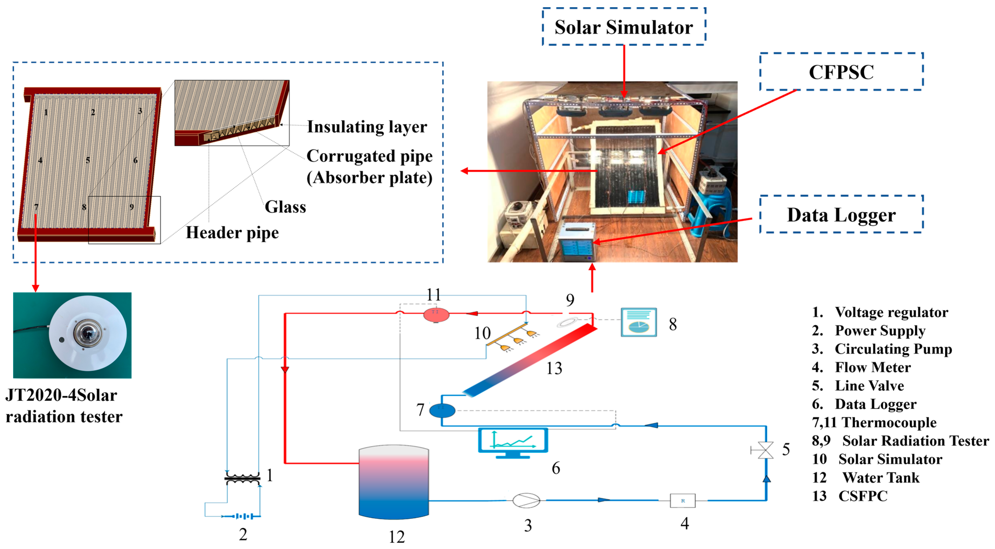
2. Description of Experiment Test Bench

To explore the effect of the CFPSC with the triangular collector tube on the heat collection performance, a test system, including the CFPSC, solar simulator, voltage regulator, circulating pump, etc., was designed, as shown in Figure 1.
As can be seen from Figure 1, the designed CFPSC with triangular collector tubes was the core component of the test system. Due to its complex structure, the main structural parameters of the CFPSC with triangular collector tubes are listed in Table 1.
In the designed test system, the iodine tungsten lamp is used as a solar simulator, which can radiate light very close to the solar spectrum (wavelength range is 0.2~2.7 μm). In order to ensure that all the radiation heat from the CFPSC comes from the solar simulator, the influence of outdoor sunlight should be avoided during the test. In addition, the solar irradiance of the test is changed by the voltage of the iodine tungsten lamp. When the solar irradiance of the measuring point is stable, or the fluctuation is small, it is regarded as the solar irradiance of the measuring point. Finally, the average value of nine measuring points is taken as the actual solar irradiance of the CFPSC. Moreover, the flow state of the fluid is determined according to the Reynolds number. When the work fluid is water, the Reynolds number is calculated as 4437.7, so the flow state is turbulent.

3. Numerical Analysis Model of CFPSC Using Nanofluid

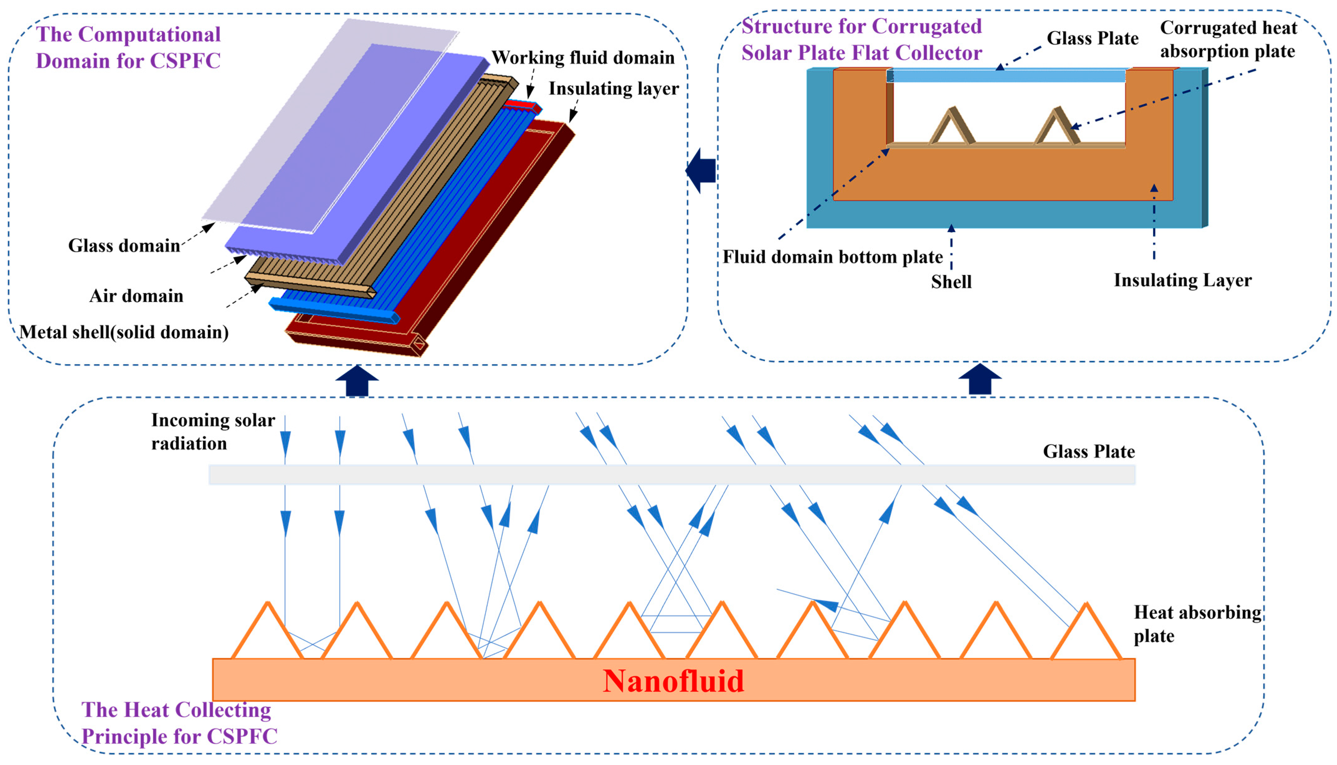
3.1. Computational Domain

In order to analyze the heat collecting performance of CFPSC using nanofluids in detail, a numerical simulation model was established. Figure 2 shows the calculation domain of the numerical model and the schematic diagram of the heat collecting principle of the corrugated plate collector.

3.2. Theoretical Governing Equations and Boundary Conditions

The governing equations for turbulent nanofluid flow inside the CFPSC can be expressed as continuity equation, energy equation, and momentum equation [34], as follows:
Continuity equation:
( ρ V ) = 0
where ρ is the density of the fluid in the working fluid domain, and V = ( u , v , w ) is the velocity field.
Momentum equation:
( ρ V V i ) = P X i + ( μ V i ) + S i
where P is the pressure of the fluid in the working fluid domain, μ is the dynamic viscosity, and the term S is the source term.
Energy equation:
( ρ V C p T ) = ( K T )
where K is the thermal conductivity of the working fluid, C p is the specific heat capacity, and T is the temperature of the working fluid.
The boundary conditions in this paper are listed in Table 2. In this study, the finite volume method was applied to solve the governing equations in the CFPSC using nanofluids. The k ε model was used in this paper. When solving the model, the heat exchange process of the corrugated flat plate collector is considered to be stable; the flow distribution of the corrugated flat plate collectors is assumed to be uniform; the thermophysical properties of the working fluid, air, and solid domain are constant; the emissivity and absorptivity of the absorber and glass do not change with temperature; and the insulation layer is insulated walls.

3.3. Physical Properties of Nanofluids

In this paper, nanofluid was a mixture of nanoparticles and base fluid, whose physical properties can be characterized by the following equations [35,36,37]:
c p , n f = ( 1 f ) ρ b f c p , b f + f ρ n p c p , n p ρ n f
K n f K b f = K n p + 2 K b f 2 f ( K b f K n p ) K n p + 2 K b f f ( K b f K n p )
ρ n f = ( 1 f ) ρ b f + f ρ n p
μ n f = μ b f 1 f 2.5
where c p is the specific heat capacity, ρ is the density of the working fluid, and f is the volume fraction of nanofluids. Also, n f and b f refer to the nanofluid and base fluid, respectively.
In this study, different nanoparticles and base fluids were used to form different nanofluids, and their compositions are shown in Table 3.

3.4. Grid Independence Verification

In the numerical simulation, the number of grids will affect the accuracy of the calculation, so grid independence verification is required, as shown in Table 4. The temperature difference between the inlet and outlet is used as the validation criterion, that is, the temperature difference will not change with the increase in grid number; the errors of the temperature difference of different grids are calculated by Equation (8).
ψ N + 1 = | Δ T N + 1 Δ T N | Δ T N × 100 %
where ψ N + 1 is the error of the N + 1th time; Δ T N + 1 is the temperature difference of the N + 1th time; and Δ T N is the temperature difference of the Nth time.
The calculation results show that the error between the fourth and third times was only 0.4%, and increasing the number of grids had little effect on temperature. Therefore, the number of grids in this paper was about 3.2 million.

3.5. Verification and Analysis

In order to verify the accuracy of the simulation, the heat collection characteristics test for CFPSC using water as the working fluid was conducted, as shown in Figure 1. The simulation temperature difference of the corrugated solar flat plate collector under different radiation conditions was compared with the corresponding experimental temperature difference. The errors under different radiation conditions were calculated by Equation (9). The results are shown in Table 5. It shows that the error of temperature difference was within 10%, which was because the simulation analysis was based on the corresponding assumptions, which cannot be avoided in the experimental process; therefore, the 10% error in this paper is considered acceptable.
ζ = Δ T s i m u Δ T exp Δ T exp × 100 %
where ζ is the error of temperature difference; Δ T s i m u is the simulated temperature difference; and Δ T exp is the experimental temperature difference.

4. Results and Analysis

In this paper, the effects of different nanofluids on the heat collection performance of corrugated flat plate collectors, including heat collection stabilization time, heat collection temperature difference, heat collection amount, and heat collection efficiency, are discussed and analyzed in detail using numerical simulations and compares the heat collection performance of the CFPSC under nanofluids with that with water as the working medium.

4.1. Effect of X-Water Nanofluids on Heat Collection Performance

When the effect of X-water nanofluid with a volume fraction of 0.05% on the heat collection performance was investigated, the glass thickness was set as 4 mm; the mass flow rate was 0.15 kg/s; the inclination angle was 45°; and the solar irradiances were set as 620, 850, 1000, and 1200 W m−2. It is noteworthy that in this section, X-water nanofluids were formed by different nanoparticles (CuO, Al2O3, and TiN) and base fluid (water).

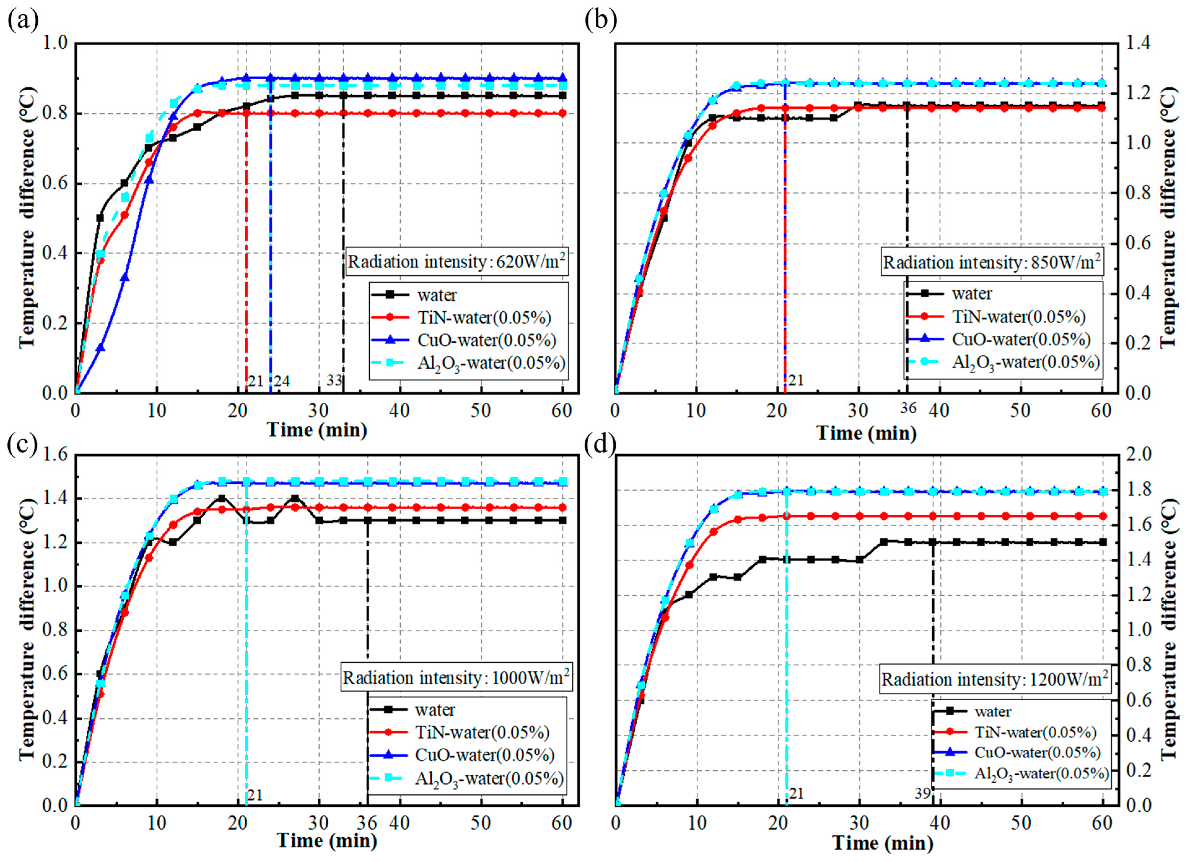
4.1.1. Effect of X-Water Nanofluids on the Stabilization Time of Heat Collection

The effect of X-water nanofluid on the stabilization time of heat collection was first explored, as shown in Figure 3. It can be seen from Figure 3 that different working fluids required different times to achieve heat collection stabilization at different radiation intensities. When the working fluid was water, the stabilization time of heat collection was 33–39 min, while the time to reach heat collection stabilization was shorter when the working fluids were X-water nanofluids. Specifically, when the solar irradiance was lower than 850 W m−2, the stabilization times of heat collection for corrugated flat plate collectors using CuO-water, Al2O3-water, and TiN-water nanofluids were 21, 24, and 24 min, respectively. However, with the increase in solar irradiance, the time of heat collection stabilization for the three different nanofluids tended to be the same, and the time of heat collection stabilization for different nanofluids was 21 min when the solar irradiance exceeded 850 W m−2.

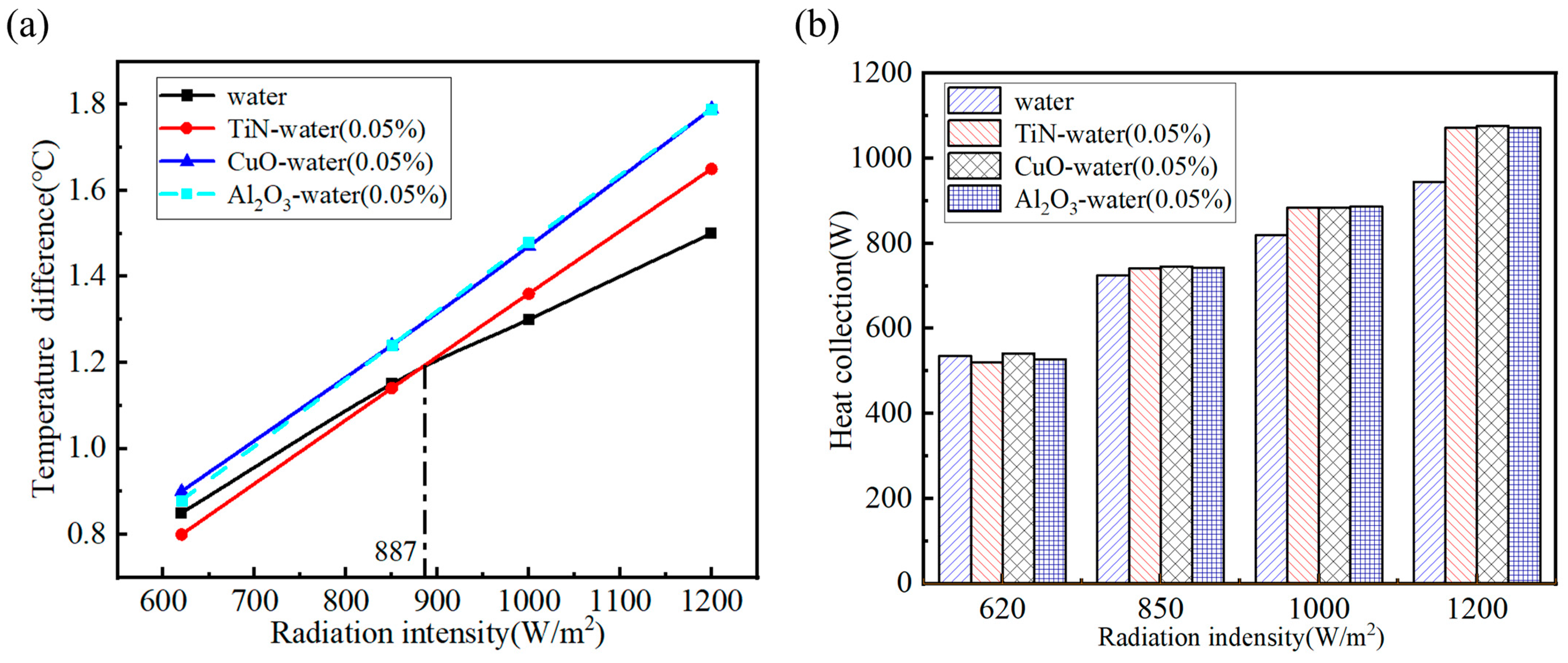
4.1.2. Effect of X-Water Nanofluids on Temperature Difference and Heat Collection

The influence of X-water nanofluids on temperature difference and heat collection is shown in Figure 4. It can be seen from Figure 4a that the temperature differences of corrugated flat plate collector with different mediums, including water, CuO-water, Al2O3-water, and TiN-water nanofluids, was positively correlated with the solar irradiance. The temperature differences of CuO-water nanofluid (Al2O3-water nanofluid) under different radiation intensities were 0.9 °C (0.88 °C), 1.24 °C (1.24 °C), 1.47 °C (1.48 °C), and 1.79 °C (1.79 °C), which was 5.9% (3.5%), 7.8% (7.8%), 13.1% (13.8%), and 19.3% (19.3%) higher than water at the same solar irradiance respectively. Moreover, when TiN-water nanofluid was used as the working medium of the corrugated flat plate collector, the temperature difference was higher than that of water only when the solar irradiance was higher than 887 W m−2. Specifically, when the solar irradiances were 1000 and 1200 W m−2, the temperature differences of TiN-water nanofluid were 1.36 and 1.65 °C, which were 4.6% and 10% higher than that of water, respectively.
Figure 4b shows the heat collection of water and different nanofluids. When the solar irradiance was lower, the temperature differences of CuO-water and Al2O3-water nanofluid were obviously higher than that of water. However, there was no significant difference between the heat collection amount of nanofluids and that of water, or even lower than that of water. The heat collections of TiN-water nanofluid and Al2O3-water nanofluid were 2.9% and 1.5% lower than that of water, respectively, which was mainly due to the variation of heat collection amount by the combined effect of heat collection temperature difference and specific heat capacity of word medium. In addition, with the increase in solar irradiance, the heat collection of nanofluids increased, but there was no significant change in the heat collection among different nanofluids. Taking TiN-water nanofluid as an example, the heat collection levels were −2.9%, 2.2%, 7.9%, and 13.5% higher than that of water at different radiation intensities.

4.1.3. Effect of X-Water Nanofluids on Heat Collection Efficiency

Heat collection efficiency is an important parameter for evaluating the heat performance of the X-water nanofluids. Figure 5 shows the variation in heat collection efficiency of different working fluids with solar irradiance. When the working fluid was water, the heat collection efficiency decreased with the increase in solar irradiance. However, when the working fluids were nanofluids, the variation trend of heat collection efficiency was slightly different. The heat collection efficiency of TiN-water nanofluid and Al2O3-water nanofluid increased with the increase in solar irradiance, but the heat collection efficiency of CuO-water nanofluid first decreased and then increased with the increase in solar irradiance. Although the variation trend of the heat collection efficiency of different nanofluids was different, there was no obvious difference in the heat collection efficiency of nanofluids with the increase in solar irradiance, and the highest heat collection efficiency was about 92%. Moreover, when the solar irradiance was lower than 733 W/m2 and 764 W/m2, the heat collection efficiencies of Al2O3-water nanofluid and TiN-water nanofluid were lower than that of water, respectively. However, under different radiation intensities, the heat collection efficiency of CuO-water nanofluid was higher than that of water, which also indicates that compared with other working fluids, the corrugated flat plate collector using CuO-water nanofluid has better heat collection performance.

4.2. Effect of CuO-X Nanofluids on Heat Collection Performance

According to the analysis in the previous section, it is found that CuO-water nanofluid had better heat collection performance. Therefore, in this section, the heat collection performance of using CuO-X nanofluid as the working medium of the corrugated flat plate collector is investigated. CuO-X represents the nanofluids formed by CuO nanoparticles and different base fluids (water and EG). In conducting comparative tests and analyzing the results, glass thickness of 4 mm, mass flow rate of 0.15 kg/s, inclination angle of 45°, and different radiation intensities (620, 850, 1000, and 1200 Wm−2) were selected as the basic parameters.

4.2.1. Effect of CuO-X Nanofluids on the Stabilization Time of Heat Collection

Figure 6 shows the effect of CuO-X nanofluids formed by different base fluids on the stabilization time of heat collection. As shown in Figure 6, when water was used as the base fluid of nanofluids, and the solar irradiance was 620 W m−2, the time of heat collection stabilization was 24 min, which can be reduced to 21 min under other radiation intensities. Compared with water, the times of heat collection stabilization were shortened by 27.3%, 41.7%, 41.7%, and 46.2%. When EG was used as the base fluid, the time of heat collection stabilization was 27 min under different radiation intensities, which were 18.2%, 25%, 25%, and 30.8% less than that of the corrugated flat plate collector using CuO-water nanofluid.

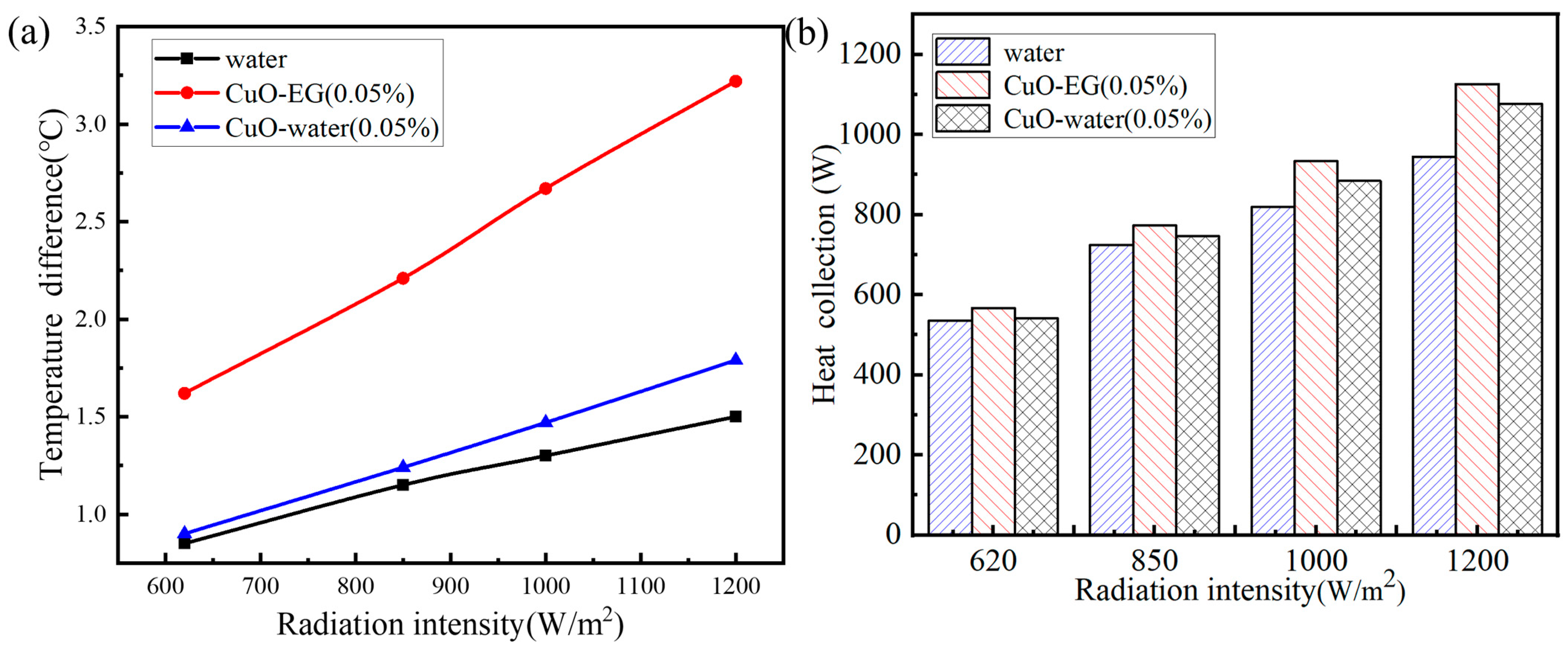
4.2.2. Effect of CuO-X Nanofluids on the Temperature Difference and Heat Collection

Figure 7a,b shows the effect of CuO-X nanofluids formed by different base fluids on the temperature difference and heat collection amount. When water was used as the base fluid, the temperature differences of CuO-water nanofluids under different radiation intensities were 0.9, 1.24, 1.47, and 1.79 °C, which were 1.1%, 3%, 8%, and 13.9% higher than that of water as the working medium of the corrugated flat plate collector, respectively. Moreover, when the solar irradiance was higher than 1000 W/m2, the heat collection was significantly improved, which was because the specific heat capacity of CuO-water nanofluid is lower than that of water, and only when the temperature difference is larger will the heat collection amount increase.
When EG was used as the base fluid, the temperature differences of CuO-EG nanofluids under different radiation intensities were 1.62, 2.21, 2.67, and 3.22 °C, which were 5.8%, 6.7%, 14%, and 19.2% higher than that of water as the working fluid, respectively. Meanwhile, the heat collection amount was obviously improved when CuO-EG was used as the working medium, and the heat collection amounts under different radiation intensities were 567 W, 773 W, 934 W, and 1126 W. Therefore, the nanofluids with EG as the base fluid have better heat collection performance.

4.2.3. Effect of CuO-X Nanofluids on Heat Collection Efficiency

Figure 8 shows the effect of nanofluid with different base fluids on the heat collection efficiency. The heat collection efficiency of CuO-EG (CuO-water) nanofluids decreased first and then increased with the increase in solar irradiance, whose heat collection efficiency was higher than that of water. The heat collection efficiencies of CuO-EG nanofluid under different radiation intensities were 3.9%, 4.3%, 5.2%, and 4.7% higher than that of CuO-water. The maximum heat collection efficiency of the CuO-water nanofluid was 92%, and that of the CuO-EG nanofluid was 96.5%. It also shows that the nanofluids whose base fluid is EG have better heat collection performance.

4.3. Effect of X-EG Nanofluids on Heat Collection Performance

According to the analysis in the previous section, nanofluids whose base fluid is EG have better heat collection performance. Therefore, EG was used as the base fluid in this section. A glass thickness of 4 mm, mass flow rate of 0.15 kg/s, an inclination angle of 45°, and different radiation intensities (620, 850, 1000, and 1200) were selected as the basic parameters. The influence of nanofluids (0.05%) formed by different nanoparticles on heat collection performance was analyzed in detail.

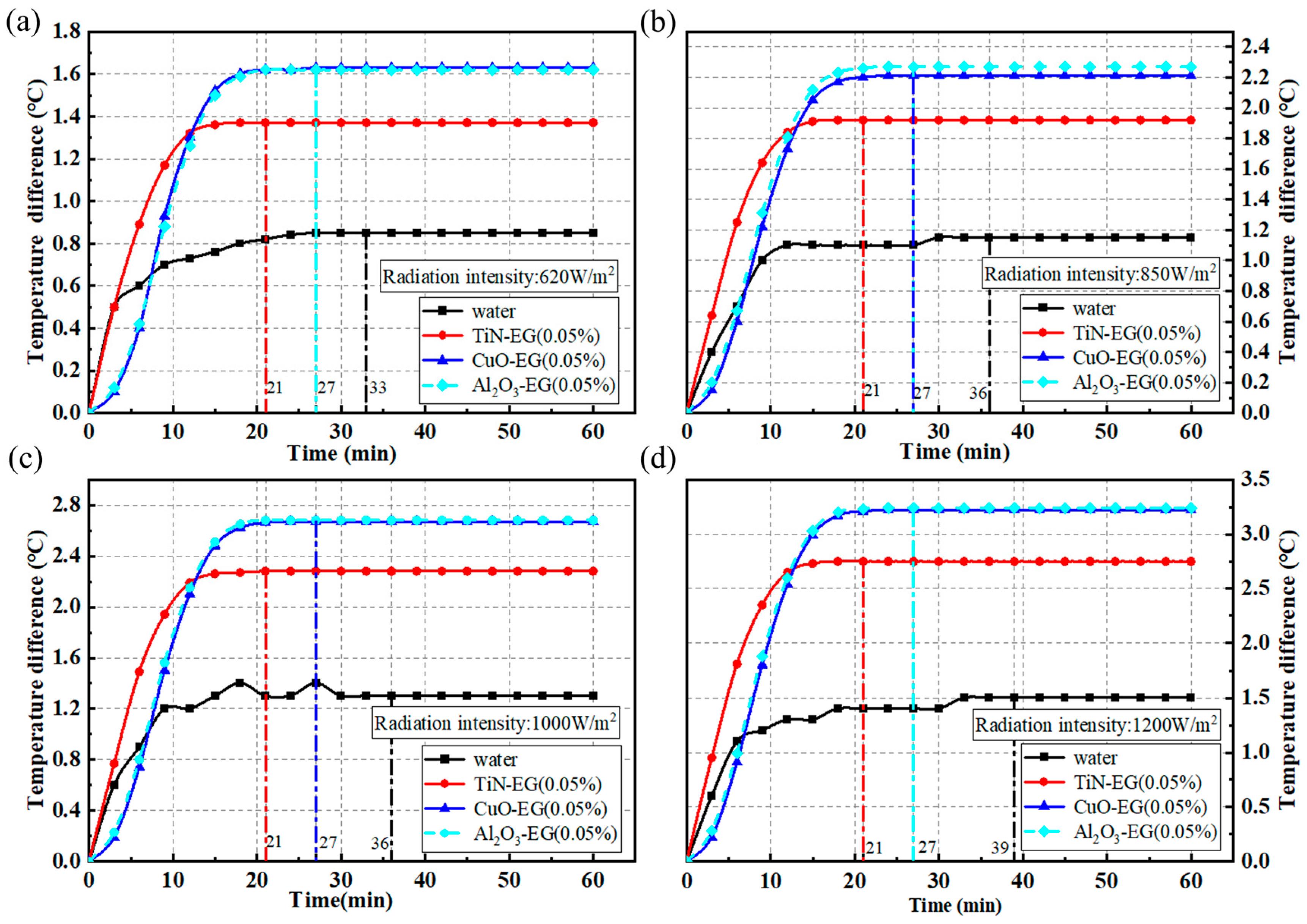
4.3.1. Effect of X-EG Nanofluids on the Stabilization Time of Heat Collection

Figure 9 shows the influence of nanofluids formed by different nanoparticles on the stabilization time of heat collection. The time required for TiN-EG nanofluid to achieve heat collection stabilization at any solar irradiance was 21 min, and the time required for CuO-EG nanofluid and Al2O3-EG nanofluid to achieve heat collection stabilization at solar irradiance was 27 min. Compared with water, the heat collection time of TiN-EG nanofluid was reduced by up to 46.2%, and that of CuO-EG and Al2O3-EG nanofluids by up to 30.8%.

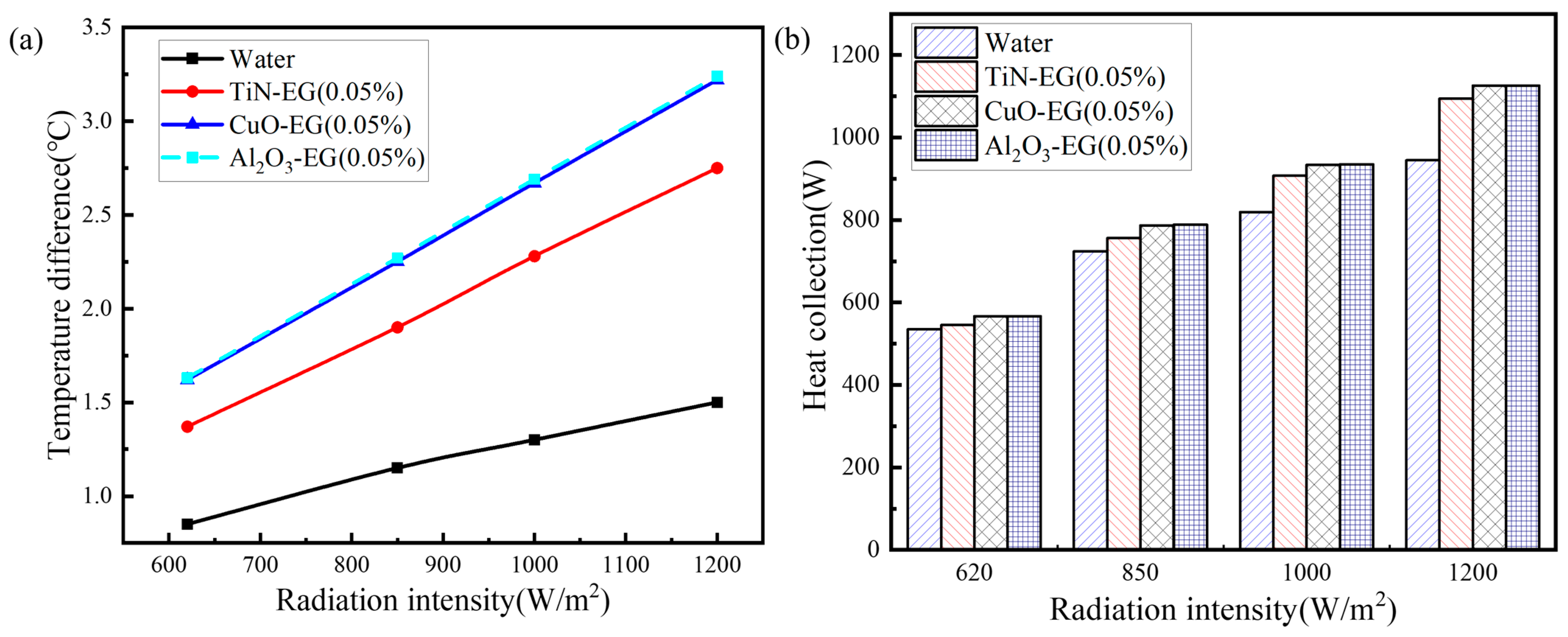
4.3.2. Effect of X-EG Nanofluids on Temperature Difference and Heat Collection

Figure 10a,b shows the effect of X-EG nanofluids on the temperature difference and heat collection amount. As shown in Figure 10, the temperature difference of X-EG nanofluids increased with the increase in solar irradiance. The temperature difference of Al2O3-EG nanofluid at any solar irradiance was almost the same as that of CuO-EG nanofluid, where the temperature differences of CuO-EG nanofluids under different radiation intensities were 1.62, 2.25, 2.67, and 3.22 °C; however, the temperature difference of TiN-EG nanofluid was lower, being 1.37, 1.9, 2.28, and 2.75 °C respectively. Compared with TiN-EG nanofluid, the temperature difference of Al2O3-EG nanofluid and CuO-EG nanofluid increased obviously, but the change in heat collection amount was very small. The heat collection amounts of CuO-EG nanofluid under different radiation intensities were only 3.8%, 4%, 2.9%, and 2.9% higher than that of TiN-EG nanofluid, which was because the temperature difference of CuO-EG nanofluid and Al2O3-EG nanofluid was higher, but their specific heat capacity was relatively lower, so their heat collection amount was not greatly improved.

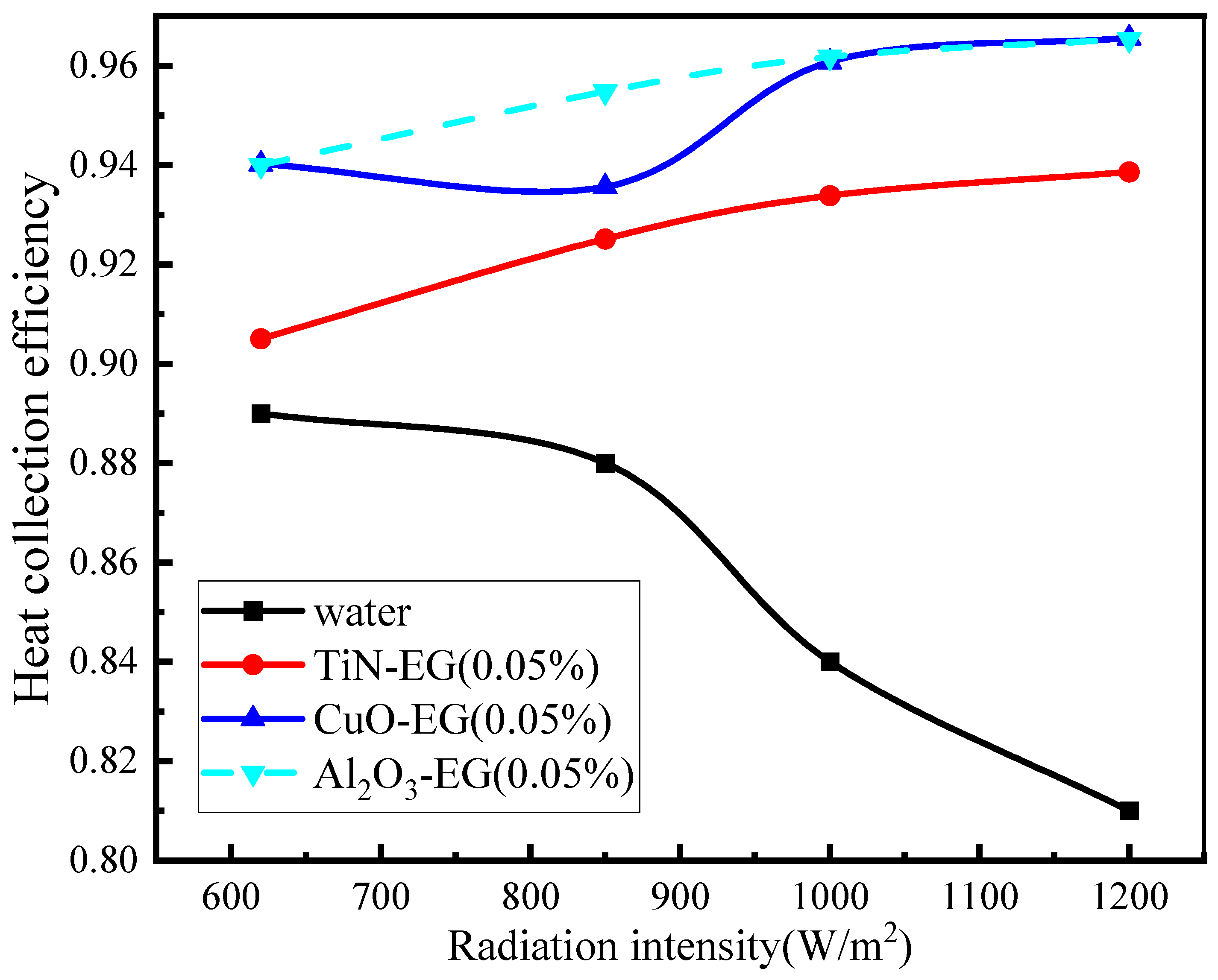
4.3.3. Effect of X-EG Nanofluids on Heat Collection Efficiency

Figure 11 shows the effect of X-EG nanofluids on the heat collection efficiency. The heat collection efficiency of Al2O3-EG nanofluid and TiN-EG nanofluid increased with the increase in solar irradiance. However, the heat collection efficiency of CuO-EG nanofluid first increased and then decreased. Although the trend of the heat collection efficiency of Al2O3-EG nanofluid and CuO-EG nanofluid was different, with the increase in radiation, their heat collection efficiency was the same. The maximum heat collection efficiency was 96.5%; the maximum heat collection efficiency of TiN-EG nanofluid was 93.8%. Compared with water, nanofluids improved the heat collection efficiency of the corrugated flat plate collector. The heat collection efficiencies of TiN-EG nanofluid under different radiation intensities were 1.7%, 5.1%, 11.2%, and 15.3% higher than that of water.

4.4. Effect of Nanofluids of Different Volume Fractions on Heat Collection Performance

According to the analysis in the previous section, nanofluids whose base fluid is EG have better heat collection performance. In this section, the effects of nanofluids with different volume fractions on heat collection performance were analyzed with the glass thickness of 4 mm, mass flow rate of 0.15 kg/s, inclination angle of 45°, and solar irradiance of 620 W/m2 as basic parameters.

4.4.1. Effect of Nanofluids of Different Volume Fractions on the Stabilization Time of Heat Collection

Figure 12 shows the effect of nanofluids of different volume fractions on the stabilization time of heat collection. The stabilization time of TiN-EG nanofluids was 21 min when the volume fractions were 0.025% and 0.05%. However, when the volume fraction was 0.075%, the stabilization time was 27 min. Al2O3-EG nanofluids and CuO-EG nanofluids had the same stabilization time at different volume fractions, both of which were 27 min.

4.4.2. Effect of Different Volume Fractions of Nanofluids on Temperature Difference and Heat Collection Amount

Figure 13 and Figure 14 show the effect of nanofluids with different volume fractions on the temperature difference and heat collection amount. The temperature difference of TiN-EG nanofluids decreased with the increase in the volume fraction of nanoparticles. The temperature differences of TiN-EG (0.025%) nanofluid under different radiation intensities were 1.66, 2.31, 2.74, and 2.31 °C. The temperature difference of TiN-EG (0.075%) nanofluid was the lowest, but the heat collection was opposite. The heat collections under different radiation intensities were 557.4, 773.7, 927.6, and 1118.9 W.
The temperature difference and heat collection of CuO-EG nanofluids and Al2O3-EG nanofluids increased with the increase in volume fraction. However, when the volume fractions were different, there was no significant difference in the temperature difference and heat collection. It indicates that the variation of volume fractions had no great influence on the temperature difference and heat collection of CuO-EG and Al2O3-EG nanofluids.

4.4.3. Effect of Nanofluids of Different Volume Fractions on Heat Collection Efficiency

Figure 15 shows the effect of nanofluids with different volume fractions on heat collection efficiency. When the volume fraction of TiN-EG nanofluid was 0.075%, the heat collection efficiency was the highest, and the value was between 0.93 and 0.96 under different radiation intensities. When the volume fraction of TiN-EG nanofluid was 0.05%, the heat collection efficiency was the lowest, and the range was 0.91–0.94 under different solar irradiance. As for the CuO-EG nanofluid, the heat collection efficiency of CuO-EG nanofluids increased with the increase in volume fractions. The highest heat collection efficiencies of CuO-EG nanofluid under different radiation intensities were 0.94, 0.956, 0.961, and 0.966. In addition, when the solar irradiance was lower than 789 W/m2, the heat collection efficiency of Al2O3-EG nanofluid, whose volume fraction was 0.05%, was the highest; when the solar irradiance was higher than 789 W/m2, the heat collection efficiency of Al2O3-EG nanofluid, whose volume fraction was 0.075%, was the highest.

5. Conclusions

Based on the heat collection characteristics test system and numerical simulation model for CFPSC with the triangular collector tube, the effect of nanofluids on heat collector performance was analyzed, and the main conclusions are as follows:
(1)
The heat stabilization time of nanofluid was less than that of water. The heat stabilization time of TiN-X nanofluid was 18~24 min. Both CuO-X nanofluids and Al2O3-X nanofluids had the same heat stabilization time, which was 24 min, and the variation of volume fraction had no obvious effect on the heat collection stabilization time of CuO-X nanofluids and Al2O3-X nanofluids.
(2)
The heat collection performance of nanofluids whose base fluid is EG was higher than that of nanofluids whose base fluid is water. On the one hand, when the base fluid was water, the temperature differences of CuO-water nanofluids under different radiation intensities were 1.1%, 3%, 8%, and 13.9% higher than that of water; when the base fluid was EG, the temperature differences of CuO-EG nanofluid under different radiation intensities were 5.8%, 6.7%, 14%, and 19.2% higher than that of water.
(3)
The heat collection performance of CuO-water (EG) nanofluids and Al2O3-water (EG) nanofluids was better than that of TiN-water (EG) nanofluids, but there was no significant difference in temperature difference and heat collection between CuO-water (EG) nanofluids and Al2O3-water (EG) nanofluids. When the basefluid was EG, the heat collections of CuO-EG nanofluid were only 3.8%, 4%, 2.9%, and 2.9% higher than that of TiN-EG nanofluid at different radiation intensities. The maximum heat efficiency of CuO-EG nanofluids and Al2O3-EG nanofluids was 96.5%, while the maximum heat efficiency of Tin-EG nanofluids was lower, at 93.8%.
(4)
The temperature difference of TiN-EG nanofluids decreased with the increase in the volume fraction of nanoparticles. However, the variation of volume fraction had no significant effect on the temperature difference and heat collection amount of CuO-EG nanofluids and Al2O3-EG nanofluids. When the volume fraction of TiN-EG nanofluid was 0.075%, the heat collection efficiency was the highest. However, when the volume fraction was 0.05%, the heat collection efficiency was the lowest. The heat collection efficiency of CuO-EG nanofluids increased with the increase in the volume fraction. The heat collection efficiencies of CuO-EG (0.075%) nanofluid under different radiation intensities were 0.94, 0.956, 0.961, and 0.966, respectively.
Based on the above key conclusions, it is important for nanofluids to be used as working fluids for CFPSC with the triangular collector tube to improve heat collection performance. In order to ensure the CFPSC with the triangular collector has the best heat collection performance, the corresponding nanofluid will be prepared for further experimental analysis, and the heat collection performance of CFPSCs under different structural parameters will be compared in the future.

Author Contributions

X.T.—conceptualization, software, validation, writing—original draft; C.T.—software, investigation, writing—review and editing; Y.L.—formal analysis, visualization; C.S.—investigation, resources, writing—review and editing; S.X.—writing—review and editing, supervision, project administration, funding acquisition. All authors have read and agreed to the published version of the manuscript.

Funding

The authors wish to acknowledge for the financial support from the National Key R&D Program of China through grant no. 2017YFB0102802 and by the National Natural Science Foundation of China through grant no. 21776221, for the work reported in this paper.

Institutional Review Board Statement

Not applicable.

Informed Consent Statement

Not applicable.

Data Availability Statement

The data presented in this study are available on request from the corresponding author.

Conflicts of Interest

The authors declare that they have no known competing financial interests or personal relationships that could have appeared to influence the work reported in this paper.

References

  1. Liu, J.; Liu, X.; Xin, J.; Zhang, Y.; Wen, L.; Liang, Q.; Miao, Z. Dual Function of the Third Component in Ternary Organic Solar Cells: Broaden the Spectrum and Optimize the Morphology. Small 2024, 20, e2308863. [Google Scholar] [CrossRef] [PubMed]
  2. Tang, X.; Yang, M.; Shi, L.; Hou, Z.; Xu, S.; Sun, C.; Tang, X.; Yang, M.; Shi, L.; Hou, Z.; et al. Adaptive state-of-health temperature sensitivity characteristics for durability improvement of PEM fuel cells. Chem. Eng. J. 2024, 491, 151951. [Google Scholar] [CrossRef]
  3. Xin, J.; Zhao, C.; Geng, Z.; Xue, W.; Chen, Z.; Song, C.; Yan, H.; Liang, Q.; Miao, Z.; Ma, W.; et al. Elucidate the Thermal Degradation Mechanism of Y6-Based Organic Solar Cells by Establishing Structure-Property Correlation. Adv. Energy Mater. 2024, 2401433. [Google Scholar] [CrossRef]
  4. Rashid, F.L.; Aljibori, H.S.; Mohammed, H.I.; Ameen, A.; Ahmad, S.; Ben Hamida, M.B.; Al-Rubaye, A.H. Recent advances and developments of the application of hybrid nanofluids in parabolic solar collector energy systems and guidelines for future prospects. J. Eng. Res. 2024, in press. [CrossRef]
  5. Sharma, H.K.; Kumar, S.; Verma, S.K. Comparative performance analysis of flat plate solar collector having circular &trapezoidal corrugated absorber plate designs. Energy 2022, 253, 124137. [Google Scholar] [CrossRef]
  6. Gao, M.; Fan, J.; Furbo, S.; Xiang, Y. Energy and exergy analysis of a glazed solar preheating collector wall with non-uniform perforated corrugated plate. Renew. Energy 2022, 196, 1048–1063. [Google Scholar] [CrossRef]
  7. Jiang, Y.; Zhang, H.; You, S.; Fan, M.; Wang, Y.; Wu, Z. Dynamic performance modeling and operation strategies for a v-corrugated flat-plate solar collector with movable cover plate. Appl. Therm. Eng. 2021, 197, 117374. [Google Scholar] [CrossRef]
  8. Tong, Y.; Chi, X.; Kang, W.; Cho, H. Comparative investigation of efficiency sensitivity in a flat plate solar collector according to nanofluids. Appl. Therm. Eng. 2020, 174, 115346. [Google Scholar] [CrossRef]
  9. Sharma, H.K.; Kumar, S.; Kumar, S.; Verma, S.K. Performance investigation of flat plate solar collector with nanoparticle enhanced integrated thermal energy storage system. J. Energy Storage 2022, 55, 105681. [Google Scholar] [CrossRef]
  10. Liu, Y.; Tan, C.; Jin, Y.; Ma, S. Heat collection performance analysis of corrugated flat plate collector: An experimental study. Renew. Energy 2022, 181, 1–9. [Google Scholar] [CrossRef]
  11. Anirudh, K.; Dhinakaran, S. Performance improvement of a flat-plate solar collector by inserting intermittent porous blocks. Renew. Energy 2020, 145, 428–441. [Google Scholar] [CrossRef]
  12. Gao, M.; Wang, D.; Liu, Y.; Wang, Y.; Zhou, Y. A study on thermal performance of a novel glazed transpired solar collector with perforating corrugated plate. J. Clean. Prod. 2020, 257, 120443. [Google Scholar] [CrossRef]
  13. Esmaeili, Z.; Akbarzadeh, S.; Rashidi, S.; Valipour, M.S. Effects of hybrid nanofluids and turbulator on efficiency improvement of parabolic trough solar collectors. Eng. Anal. Bound. Elem. 2023, 148, 114–125. [Google Scholar] [CrossRef]
  14. Geovo, L.; Ri, G.D.; Kumar, R.; Verma, S.K.; Roberts, J.J.; Mendiburu, A.Z. Theoretical model for flat plate solar collectors operating with nanofluids: Case study for Porto Alegre, Brazil. Energy 2023, 263, 125698. [Google Scholar] [CrossRef]
  15. Alawi, O.A.; Kamar, H.M.; Mallah, A.; Mohammed, H.A.; Kazi, S.; Sidik, N.A.C.; Najafi, G. Nanofluids for flat plate solar collectors: Fundamentals and applications. J. Clean. Prod. 2021, 291, 125725. [Google Scholar] [CrossRef]
  16. Balakin, B.V.; Struchalin, P.G. Eco-friendly and low-cost nanofluid for direct absorption solar collectors. Mater. Lett. 2023, 330, 133323. [Google Scholar] [CrossRef]
  17. Aissa, A.; Qasem, N.A.; Mourad, A.; Laidoudi, H.; Younis, O.; Guedri, K.; Alazzam, A. A review of the enhancement of solar thermal collectors using nanofluids and turbulators. Appl. Therm. Eng. 2023, 220, 119663. [Google Scholar] [CrossRef]
  18. Almanassra, I.W.; Manasrah, A.D.; Al-Mubaiyedh, U.A.; Al-Ansari, T.; Malaibari, Z.O.; Atieh, M.A. An experimental study on stability and thermal conductivity of water/CNTs nanofluids using different surfactants: A comparison study. J. Mol. Liq. 2020, 304, 111025. [Google Scholar] [CrossRef]
  19. Sahin, A.Z.; Uddin, M.A.; Yilbas, B.S.; Al-Sharafi, A. Performance enhancement of solar energy systems using nanofluids: An updated review. Renew. Energy 2020, 145, 1126–1148. [Google Scholar] [CrossRef]
  20. Shi, L.; Zhang, S.; Arshad, A.; Hu, Y.; He, Y.; Yan, Y. Thermo-physical properties prediction of carbon-based magnetic nanofluids based on an artificial neural network. Renew. Sustain. Energy Rev. 2021, 149, 111341. [Google Scholar] [CrossRef]
  21. Ali, B.; Siddique, I.; Ahmadian, A.; Senu, N.; Ali, L.; Haider, A. Significance of Lorentz and Coriolis forces on dynamics of water based silver tiny particles via finite element simulation. Ain Shams Eng. J. 2022, 13, 101572. [Google Scholar] [CrossRef]
  22. Rehman, S.U.; Fatima, N.; Ali, B.; Imran, M.; Ali, L.; Shah, N.A.; Chung, J.D. The Casson Dusty Nanofluid: Significance of Darcy–Forchheimer Law, Magnetic Field, and Non-Fourier Heat Flux Model Subject to Stretch Surface. Mathematics 2022, 10, 2877. [Google Scholar] [CrossRef]
  23. Choi, S. Enhancing thermal conductivity of fluids with nanoparticles, developments and applications of non-Newtonian flows. ASME FED 1995, 105, 231. [Google Scholar]
  24. Dharmakkan, N.; Srinivasan, P.M.; Muthusamy, S.; Jomde, A.; Shamkuwar, S.; Sonawane, C.; Sharma, K.; Alrubaie, A.J.; El Shafay, A.; Panchal, H. A case study on analyzing the performance of microplate heat exchanger using nanofluids at different flow rates and temperatures. Case Stud. Therm. Eng. 2023, 44, 102805. [Google Scholar] [CrossRef]
  25. Deshmukh, K.; Karmare, S.; Patil, P. Experimental investigation of convective heat transfer performance of TiN nanofluid charged U-pipe evacuated tube solar thermal collector. Appl. Therm. Eng. 2023, 225, 120199. [Google Scholar] [CrossRef]
  26. Shojaeizadeh, E.; Veysi, F.; Goudarzi, K. Heat transfer and thermal efficiency of a lab-fabricated ferrofluid-based single-ended tube solar collector under the effect of magnetic field: An experimental study. Appl. Therm. Eng. 2020, 164, 114510. [Google Scholar] [CrossRef]
  27. Akram, N.; Montazer, E.; Kazi, S.; Soudagar, M.E.M.; Ahmed, W.; Zubir, M.N.M.; Afzal, A.; Muhammad, M.R.; Ali, H.M.; Márquez, F.P.G.; et al. Experimental investigations of the performance of a flat-plate solar collector using carbon and metal oxides based nanofluids. Energy 2021, 227, 120452. [Google Scholar] [CrossRef]
  28. Mirzaei, M.; Hosseini, S.M.S.; Kashkooli, A.M.M. Assessment of Al2O3 nanoparticles for the optimal operation of the flat plate solar collector. Appl. Therm. Eng. 2018, 134, 68–77. [Google Scholar] [CrossRef]
  29. Ge, Z.; Xiang, Q.; Li, J.; Zhang, S.; Wang, Z.; Xie, J.; Xie, Z.; Yang, F. Thermo-economic analysis of organic Rankine cycle using a new two-stage solar collector with nanofluids. Int. J. Heat Fluid Flow 2024, 107, 109393. [Google Scholar] [CrossRef]
  30. Struchalin, P.G.; Zhao, Y.; Balakin, B.V. Field study of a direct absorption solar collector with eco-friendly nanofluid. Appl. Therm. Eng. 2024, 243, 122652. [Google Scholar] [CrossRef]
  31. Alawi, O.A.; Kamar, H.M.; Mallah, A.; Kazi, S.; Sidik, N.A.C. Thermal efficiency of a flat-plate solar collector filled with Pentaethylene Glycol-Treated Graphene Nanoplatelets: An experimental analysis. Sol. Energy 2019, 191, 360–370. [Google Scholar] [CrossRef]
  32. Sathish, T.; Giri, J.; Saravanan, R.; Ubaidullah, M.; Shangdiar, S.; Iikela, S.; Sithole, T.; Amesho, K.T. Amplifying thermal performance of solar flat plate collector by Al2O3/Cu/MWCNT/SiO2 mono and hybrid nanofluid. Appl. Therm. Eng. 2024, 252, 123692. [Google Scholar] [CrossRef]
  33. Aytaç, I.; Tuncer, A.D.; Khanlari, A.; Variyenli, H.I.; Mantıcı, S.; Güngör, L.; Ünvar, S. Investigating the effects of using MgO-CuO/water hybrid nanofluid in an evacuated solar water collector: A comprehensive survey. Therm. Sci. Eng. Prog. 2023, 39, 101688. [Google Scholar] [CrossRef]
  34. Choudhary, S.; Sachdeva, A.; Kumar, P. Investigation of the stability of MgO nanofluid and its effect on the thermal performance of flat plate solar collector. Renew. Energy 2020, 147 Pt 1, 1801–1814. [Google Scholar] [CrossRef]
  35. Khanafer, K.; Vafai, K. A critical synthesis of thermophysical characteristics of nanofluids. Int. J. Heat Mass Transf. 2011, 54, 4410–4428. [Google Scholar] [CrossRef]
  36. Xuan, Y.; Roetzel, W. Conceptions for heat transfer correlation of nanofluids. Int. J. Heat Mass Transf. 2000, 43, 3701–3707. [Google Scholar] [CrossRef]
  37. Chon, C.H.; Kihm, K.D.; Lee, S.P.; Choi, S.U.S. Empirical correlation finding the role of temperature and particle size for nanofluid (Al2O3) thermal conductivity enhancement. Appl. Phys. Lett. 2005, 87, 153107. [Google Scholar] [CrossRef]
Figure 1. The heat collection characteristics test system for the CFPSC with a triangular collector tube.
Sustainability 16 05924 g001
Figure 2. The numerical calculation model of the CFPSC with a triangular collector tube.
Sustainability 16 05924 g002
Figure 3. Comparative analysis of the heat collection time of X-water nanofluids. (a) Temperature difference at the radiation intensity of 620 W/m2; (b) Temperature difference at the radiation intensity of 850 W/m2; (c) Temperature difference at the radiation intensity of 1000 W/m2; (d) Temperature difference at the radiation intensity of 1200 W/m2.
Sustainability 16 05924 g003
Figure 4. Comparative analysis of temperature difference and heat collection of X-water nanofluids. (a) Temperature difference; (b) Heat collection.
Sustainability 16 05924 g004
Figure 5. Comparative analysis of the heat collection efficiency of X-water nanofluids.
Sustainability 16 05924 g005
Figure 6. Comparative analysis of the stabilization time of heat collection for CuO-X nanofluids. (a) Temperature difference at the radiation intensity of 620 W/m2; (b) Temperature difference at the radiation intensity of 850 W/m2; (c) Temperature difference at the radiation intensity of 1000 W/m2; (d) Temperature difference at the radiation intensity of 1200 W/m2.
Sustainability 16 05924 g006
Figure 7. Comparative analysis of the temperature difference and heat collection of CuO-X nanofluids. (a) Temperature difference; (b) Heat collection.
Sustainability 16 05924 g007
Figure 8. Comparative analysis of the heat collection efficiency of CuO-X nanofluids.
Sustainability 16 05924 g008
Figure 9. Comparative analysis of the heat collection time of X-EG nanofluids. (a) Temperature difference at the radiation intensity of 620 W/m2; (b) Temperature difference at the radiation intensity of 850 W/m2; (c) Temperature difference at the radiation intensity of 1000 W/m2; (d) Temperature difference at the radiation intensity of 1200 W/m2.
Sustainability 16 05924 g009
Figure 10. Comparative analysis of the temperature difference and heat collection of X-EG nanofluids. (a) Temperature difference; (b) Heat collection.
Sustainability 16 05924 g010
Figure 11. Comparative analysis of the heat collection efficiency of X-EG nanofluids.
Sustainability 16 05924 g011
Figure 12. Heat collection time of nanofluids of different volume fractions. (a) Temperature difference of the TiN-EG; (b) Temperature difference of the CuO-EG; (c) Temperature difference of the Al2O3-EG.
Sustainability 16 05924 g012
Figure 13. The temperature difference of nanofluids of different volume fractions. (a) Temperature difference of the TiN-EG; (b) Temperature difference of the Cuo-EG; (c) Temperature difference of the Al2O3-EG.
Sustainability 16 05924 g013
Figure 14. The heat collection of different volume fractions of nanofluids. (a) Heat collection of the TiN-EG; (b) Heat collection of the CuO-EG; (c) Heat collection of the Al2O3-EG.
Sustainability 16 05924 g014
Figure 15. The heat collection efficiency of nanofluids of different volume fractions. (a) Heat collection efficiency of the TiN-EG; (b) Heat collection efficiency of the CuO-EG; (c) Heat collection efficiency of the Al2O3-EG.
Sustainability 16 05924 g015
Table 1. Structure parameters of the CFPSC with a triangular collector tube.
ComponentParam.UnitValue
CFPSCLengthmm1060
Widthmm823
Heightmm50
AbsorberLengthmm1000
Edge lengthmm27
Thicknessmm1
Thermal conductivity W m 1 K 1 397
Quantity-18
Absorptivity-0.98
Insulating layerThicknessmm55
Thermal conductivity W m 1 K 1 0.034
Glass coverLengthmm1400
Widthmm1200
Thicknessmm4
Transmittance-0.92
Table 2. Boundary condition parameters.
Boundary NameBoundary Condition
Inletmass flow inlet
Outletpressure outlet
GlassSemi-transparnet, transmissivity: 0.92
Absorptivity: 0.02
Absorbercoupled
Absorptivity: 0.96
Emissivity: 0.8
Insulation layerAdiabatic
Table 3. The compositions of different nanofluids.
X-Water NanofluidsCuO-X NanofluidsX-EG Nanofluids
Nanoparticlesbase fluidnanoparticlebase fluidsnanoparticlesbase fluid
CuO/Al2O3/TiNwaterCuOwater/EGCuO/Al2O3/TiNEG
Table 4. Variation of temperature difference with the grid.
NNumber Temperature Difference (K)Error ( ψ )
11,756,6650.882
22,306,6440.9032.3%
33,261,3240.9313.1%
44,659,2900.9350.4%
55,925,7660.9340.1%
Table 5. Temperature difference analysis of different radiation intensities.
Solar Irradiance (W/m2)Experimental Value (K)Simulated Value (K)Error ( ζ )
6200.850.939.4%
8501.151.258.7%
10001.341.499.7%
12001.541.689.1%
Disclaimer/Publisher’s Note: The statements, opinions and data contained in all publications are solely those of the individual author(s) and contributor(s) and not of MDPI and/or the editor(s). MDPI and/or the editor(s) disclaim responsibility for any injury to people or property resulting from any ideas, methods, instructions or products referred to in the content.

