
Numerical Study on the Mechanical Performance of a Flexible Arch Composite Bridge with Steel Truss Beams over Its Entire Lifespan


Abstract
:1. Introduction
2. Flexible Arch Composite Bridges with Steel Truss Beams
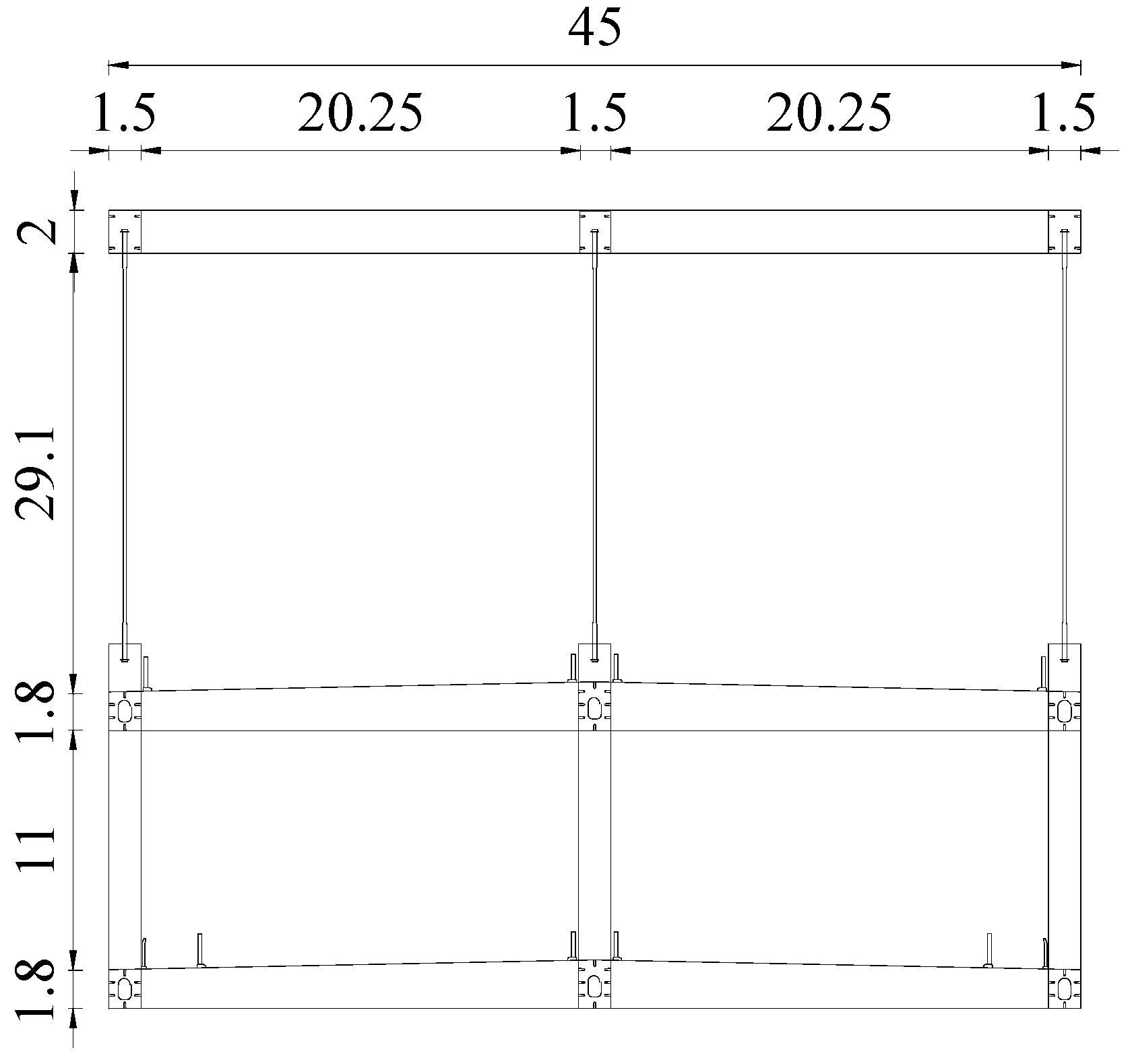
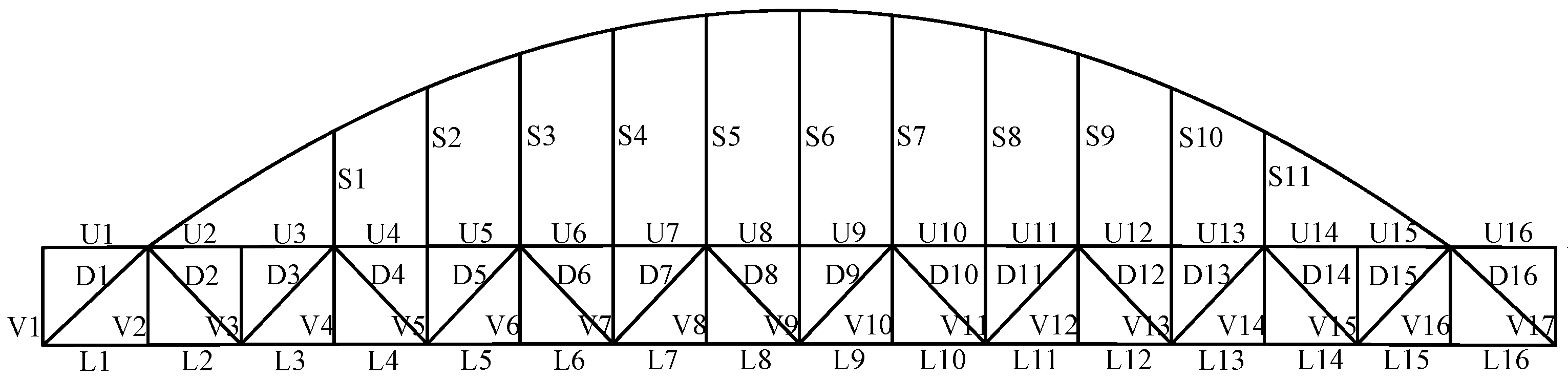
2.1. Bridge Configuration
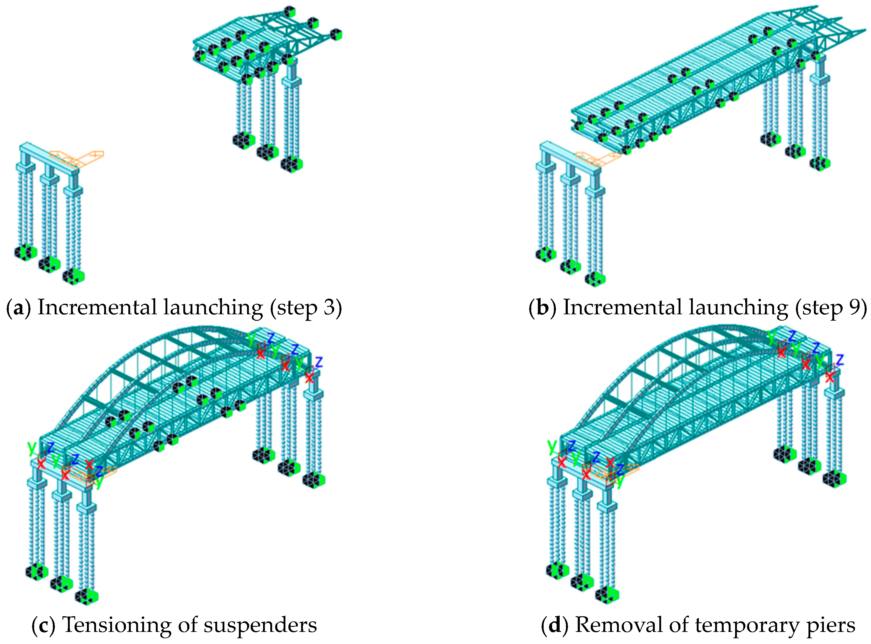
2.2. Construction Procedure
3. Numerical Study
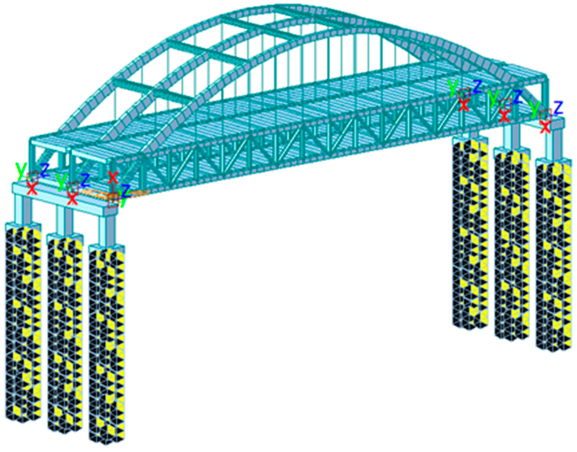
3.1. Numerical Study of the Construction Procedure
3.2. Verification of the Numerical Model
4. Analysis of the Construction Phase
4.1. Incremental Launching
4.2. Installation of Arch Ribs
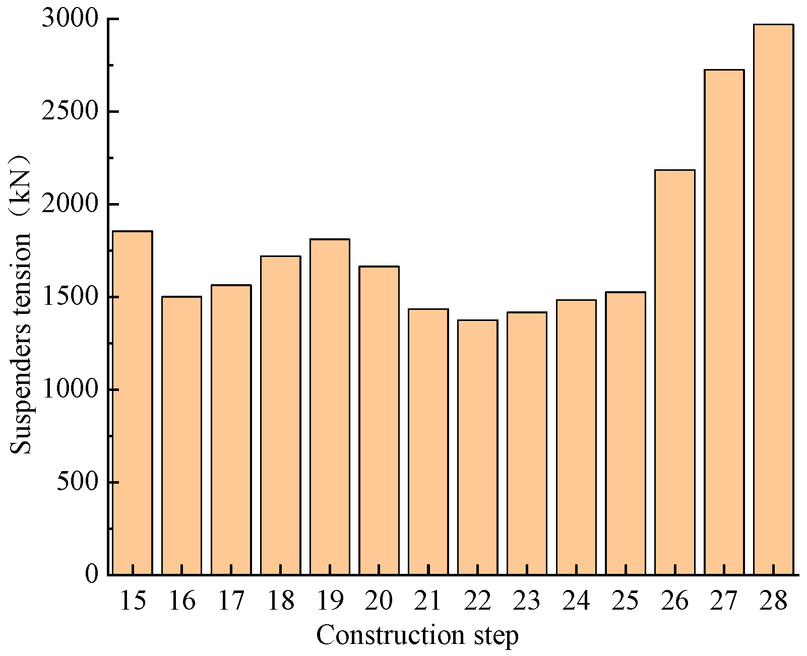
4.3. Tensioning the Suspenders
4.4. Removal of Temporary Piers
4.5. Secondary Dead Load
4.6. Adjusting the Tension in the Suspenders
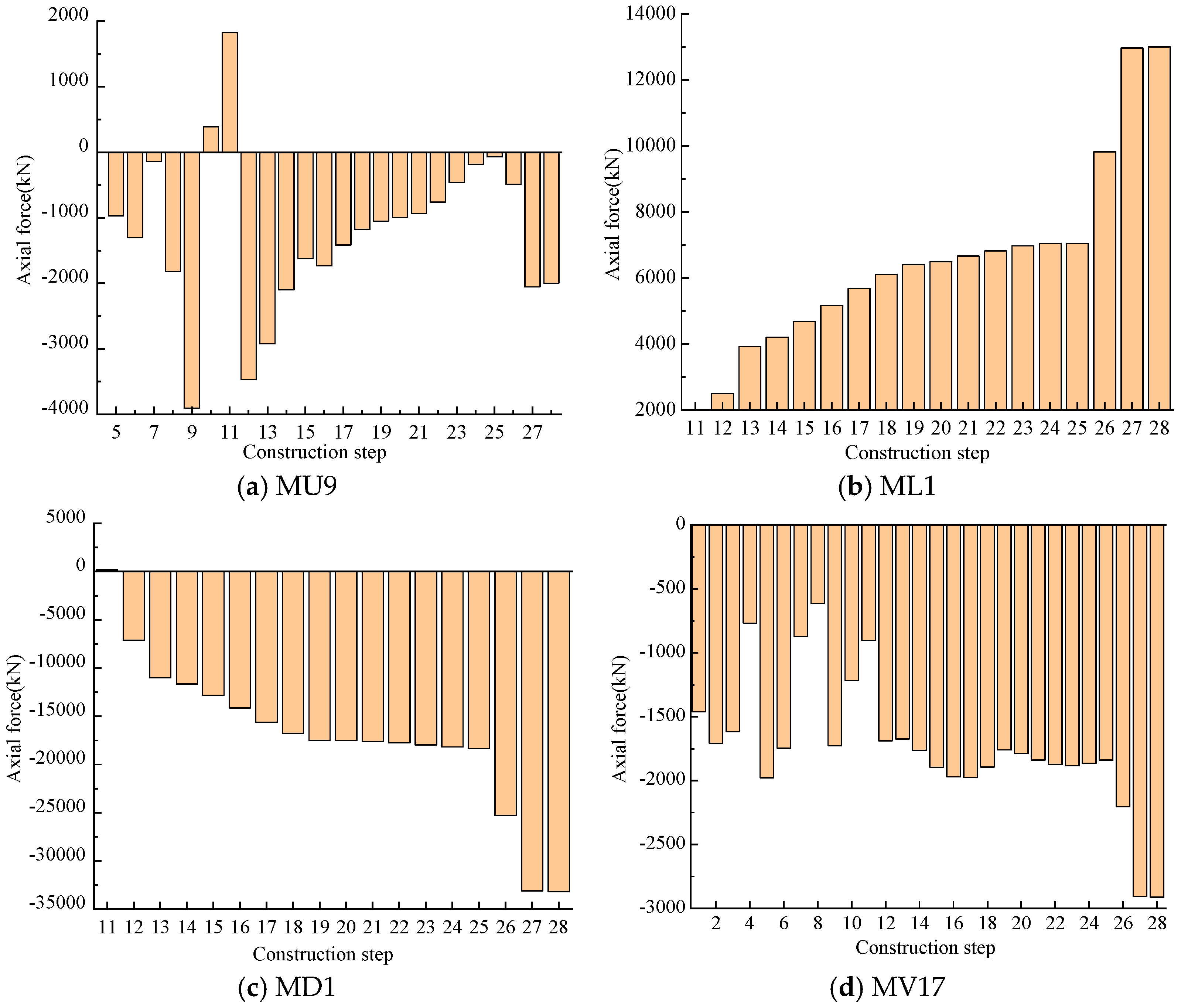
4.7. Axial Forces during Construction
5. Service Period
6. Conclusions
- (1)
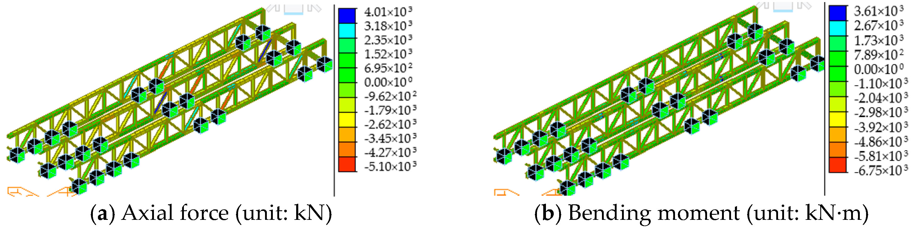
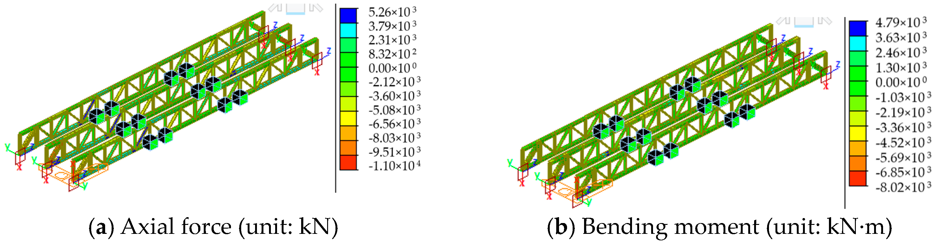
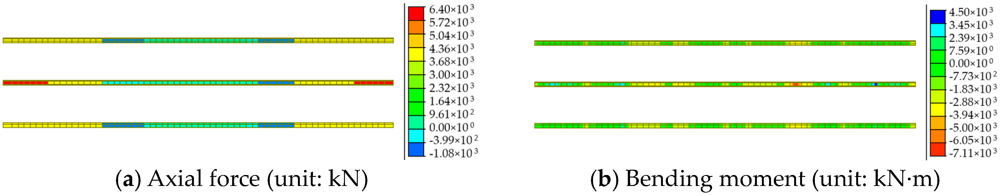
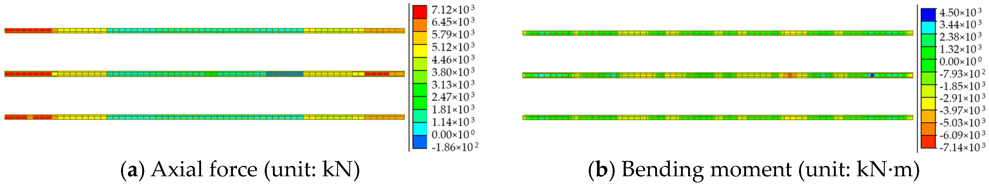
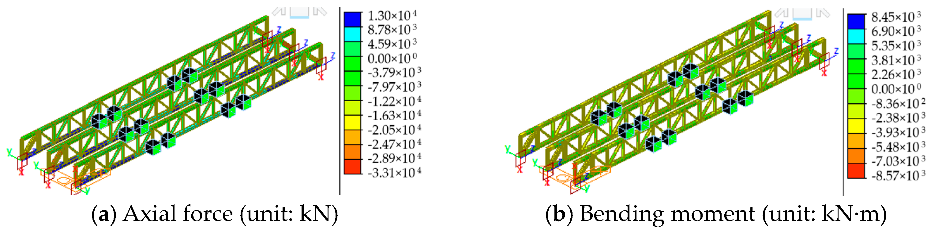
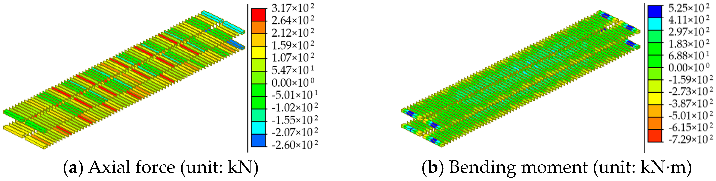
- The axial force and bending moment of the steel truss members increased during incremental launching. The removal of the guide beam and the installation of the permanent supports caused significant changes in the axial force of the critical chords MU9 and ML1 from 1827 kN and 104 kN to −3474 kN and 2492 kN, respectively. The removal of the temporary piers and the bridge deck paving resulted in significant increases in the axial forces to −2057 kN and 12,964 kN, as well as a significant increase to 33,101 kN in diagonal bar MD1.
- (2)
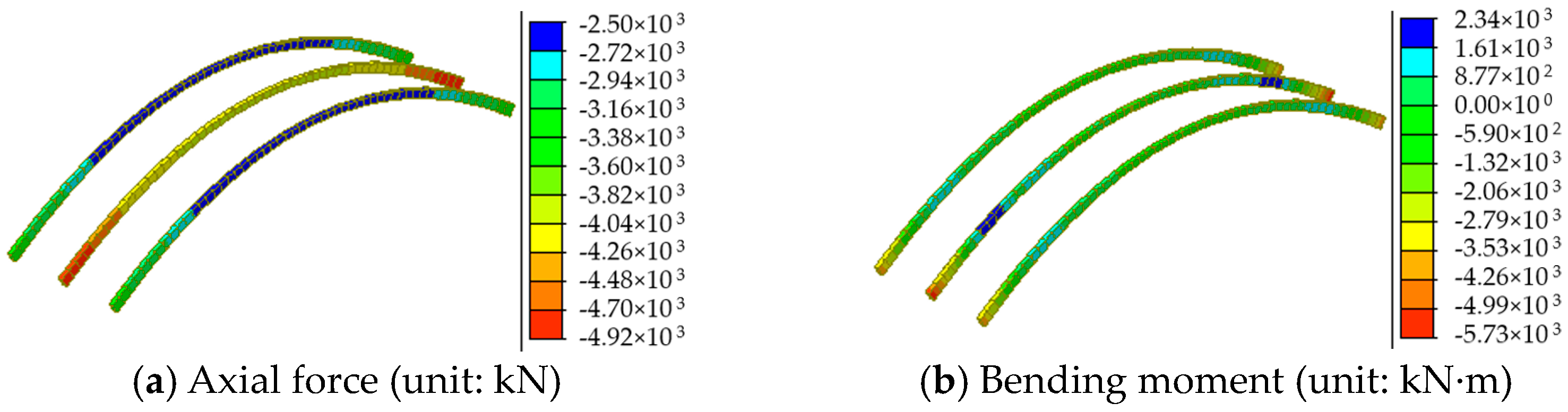
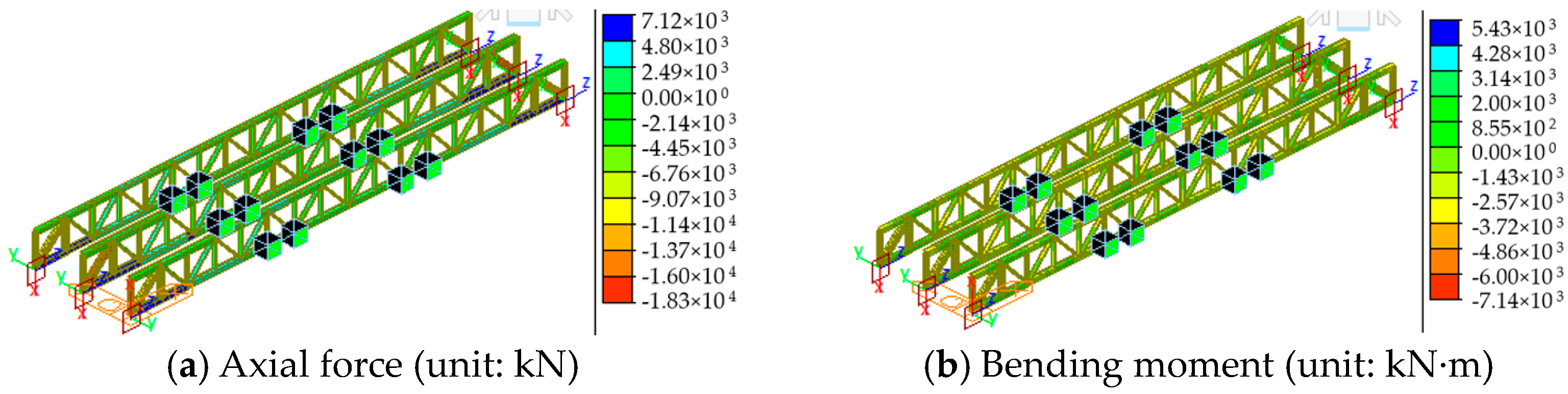
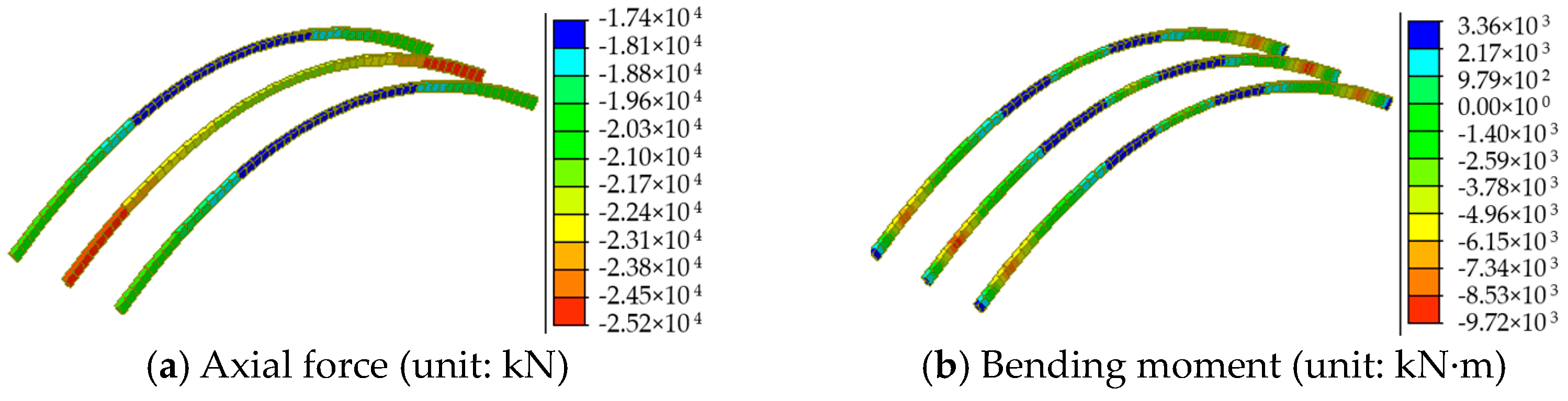
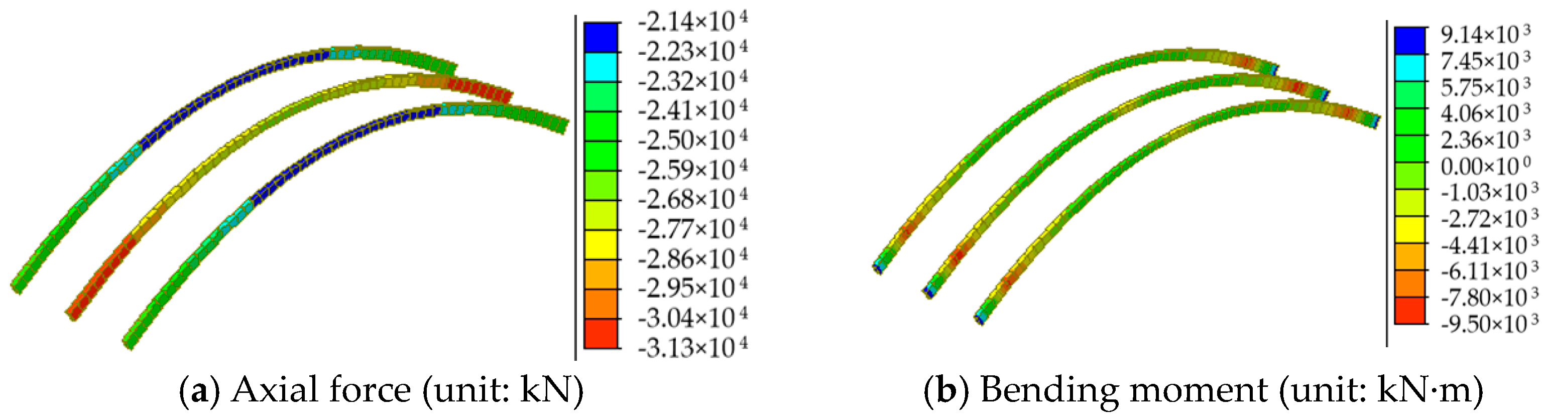
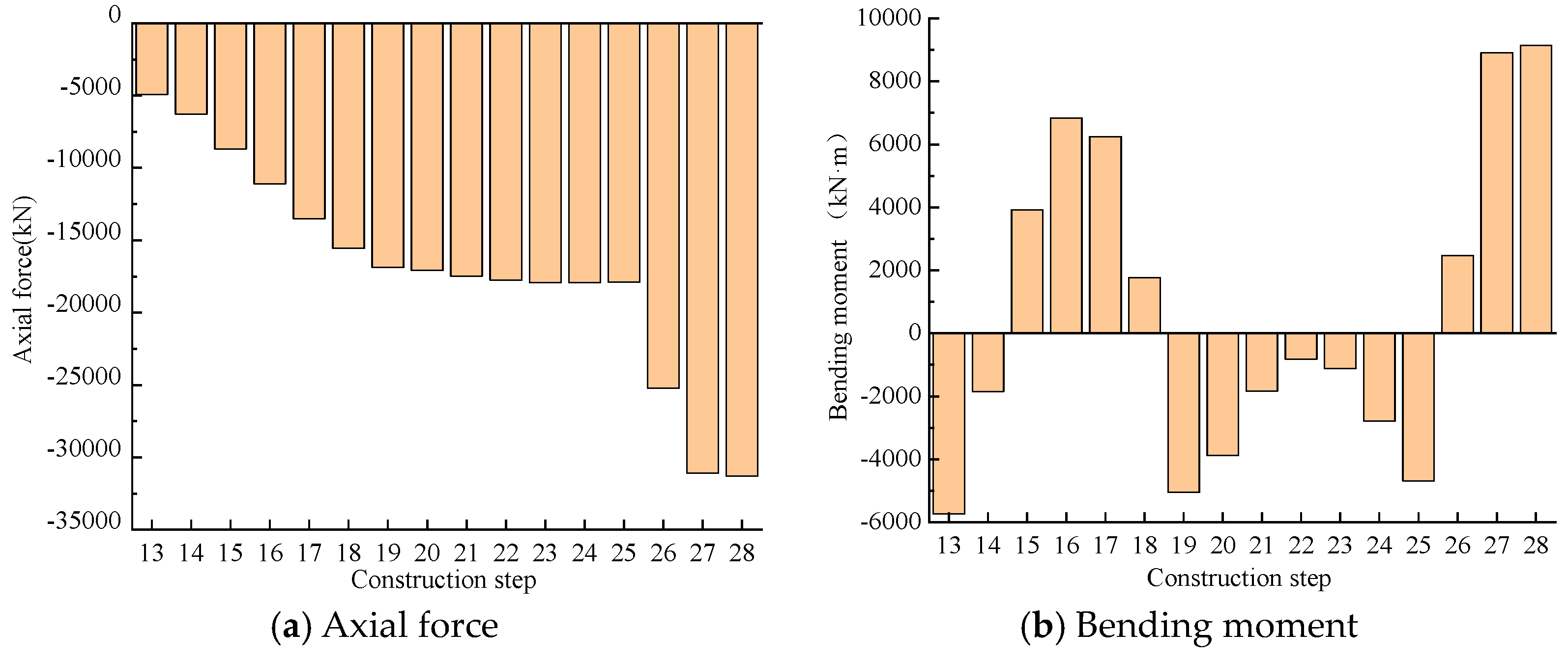
- Tensioning the suspenders caused a significant increase in the compressive axial force at the foot of the middle arch from 4920 kN to 17,909 kN. The removal of the temporary piers caused increases in the forces and bending moment to 31,291 kN and 8908 kN·m, respectively. Therefore, the removal of the temporary piers and bridge deck paving significantly influenced the bridge’s mechanical performance. Thus, monitoring and inspection of critical members is necessary in both construction phases.
- (3)
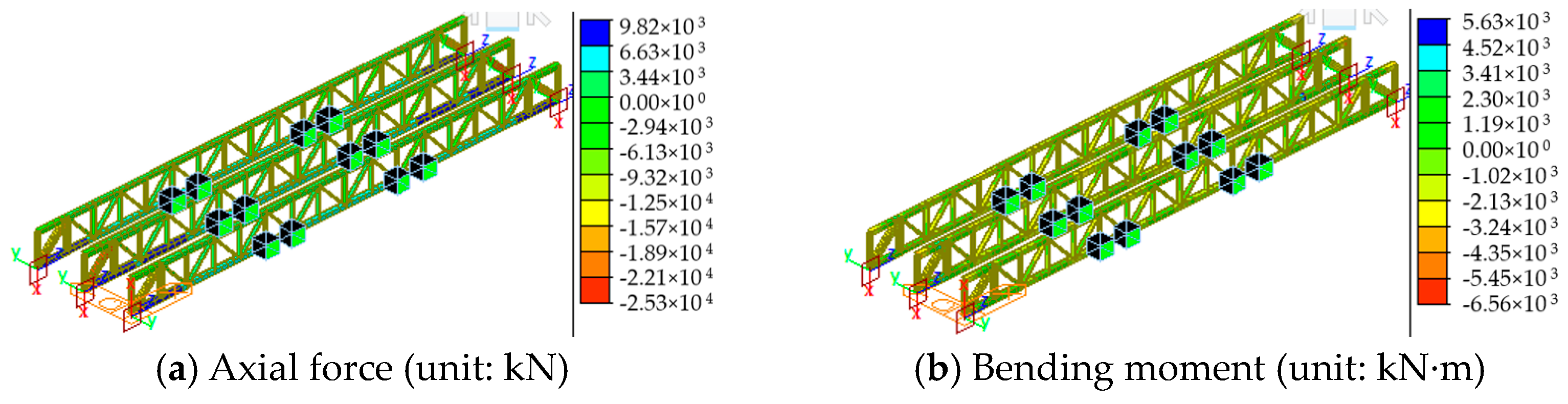
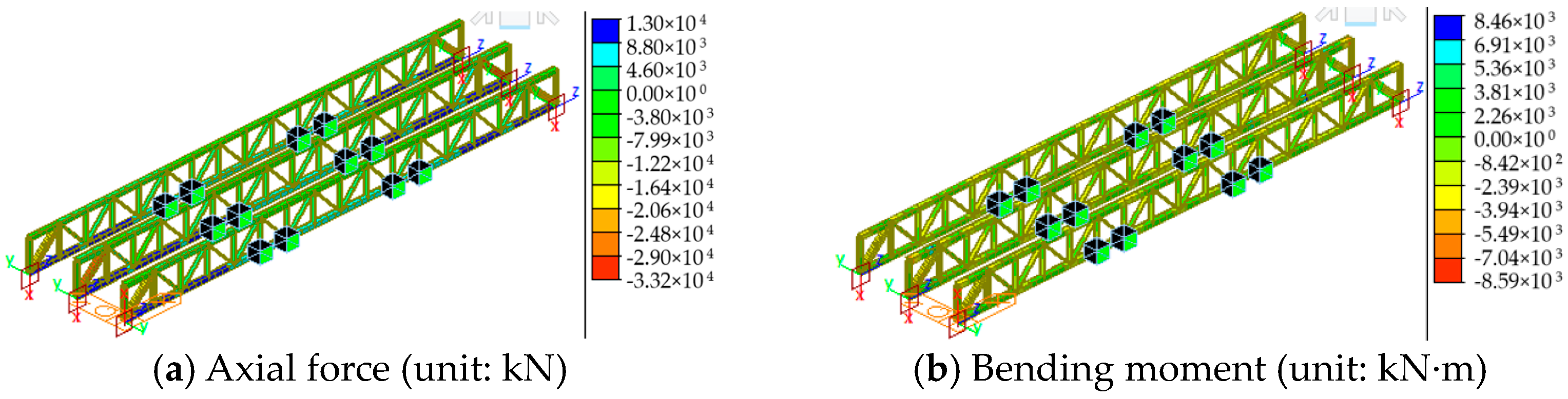
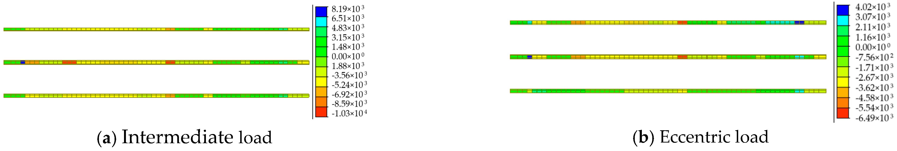
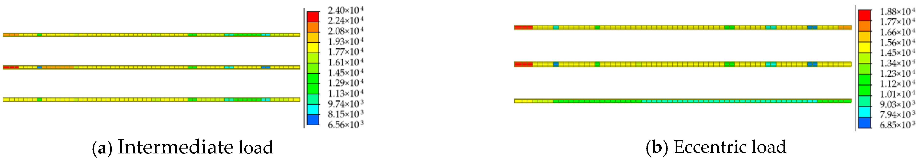
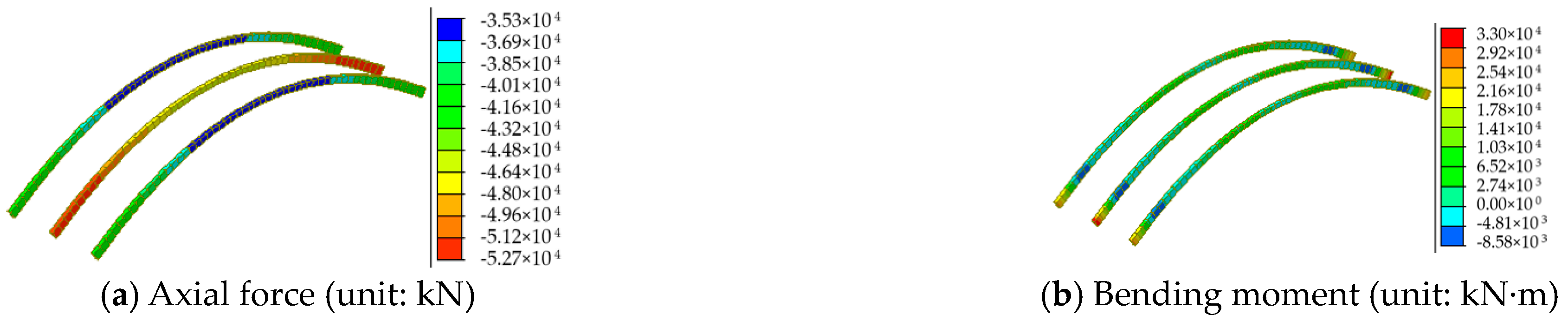
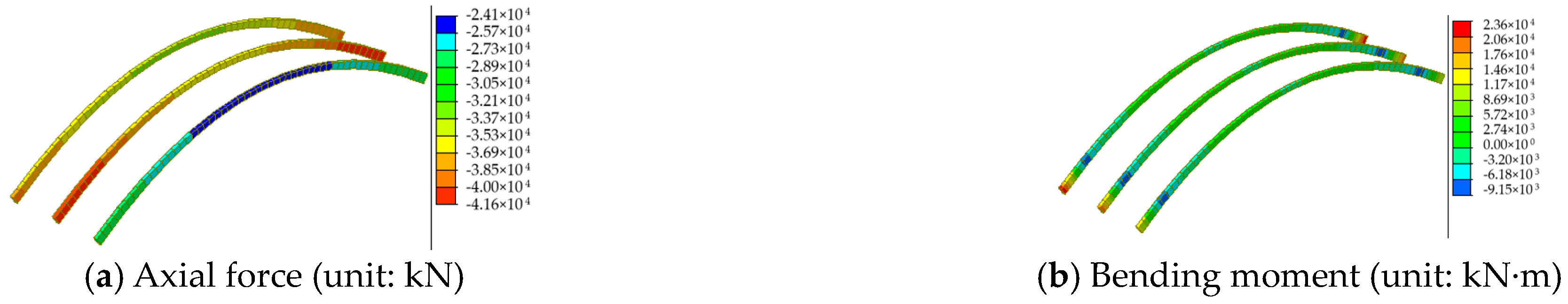
- The axial forces of the critical members, including declining bar MD1 and chords ML1 and MU9, increased by 92%, 85%, and 4.1 times, respectively, in the critical load scenarios. The vehicle loads significantly affected the critical members’ mechanical performance, necessitating monitoring and inspection of these members to increase the bridge’s safety and sustainable service life.
- (4)
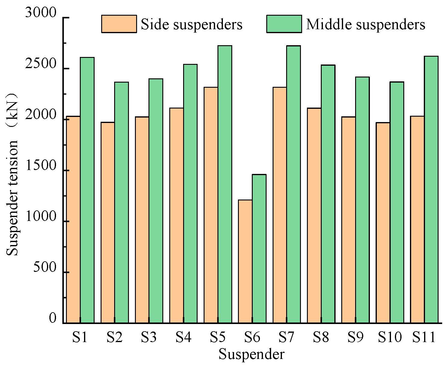
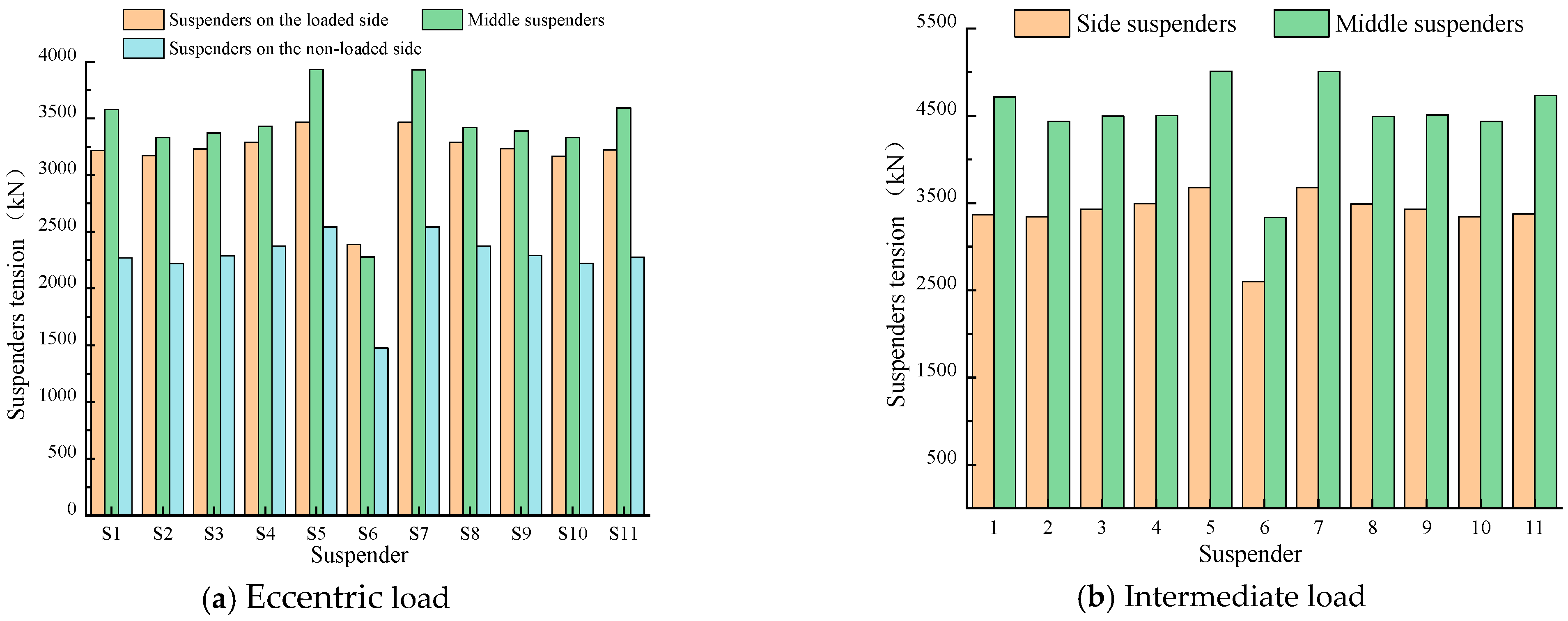
- The suspender tensions and maximum vertical displacement are probably larger than the limit in service stage, triggered by the insufficient longitudinal bending stiffness of truss beams, which could be resolved by increasing the height of these trusses. Besides, the maximum difference in the vertical displacement between the two sides of the bridge under a critical eccentric load was only 0.11 m due to the sufficient bending stiffness of the crossbeams.
Author Contributions
Funding
Institutional Review Board Statement
Informed Consent Statement
Data Availability Statement
Conflicts of Interest
References
- Shen, Z.; Liu, Y.; Liu, J.; Liu, Z.; Han, S.; Lan, S. A Decision-Making Method for Bridge Network Maintenance Based on Disease Transmission and NSGA-II. Sustainability 2023, 15, 5007. [Google Scholar] [CrossRef]
- Parida, S.; Talukdar, S. An Insight to the Dynamic Amplification Factor for Steel Truss Girder Bridge. Int. J. Steel Struct. 2020, 20, 1341–1354. [Google Scholar] [CrossRef]
- Buitrago, M.; Bertolesi, E.; Calderón, P.A.; Adam, J.M. Robustness of steel truss bridges: Laboratory testing of a full-scale 21-metre bridge span. Structures 2021, 29, 691–700. [Google Scholar] [CrossRef]
- Huang, H.; Yang, K. Analysis on load distribution of beam-arch combination system bridge. IOP Conf. Ser. Earth Environ. Sci. 2021, 647, 012214. [Google Scholar] [CrossRef]
- Li, H. Evaluation of safety performance during construction and servicing stages of Liuxi river bridge. Vibroeng. Procedia 2020, 30, 199–204. [Google Scholar] [CrossRef]
- Li, J.; Cui, H.; Ma, Z.; Liu, H.; Hu, Y. Study of impact factor of arch bridge made with continuous composite concrete filled steel tube beams. Bridge Struct. 2023, 18, 89–100. [Google Scholar] [CrossRef]
- Fu, M.; Liang, Y.; Wu, B.; Zhang, L.; Tang, G. Research on Deformation Analysis and Rehabilitation for a Beam–Arch Combination Bridge Suffering an Extreme Temperature Field. Appl. Sci. 2022, 12, 6909. [Google Scholar] [CrossRef]
- Stojanović, V.; Petković, D.M.; Milić, D. Nonlinear vibrations of a coupled beam-arch bridge system. J. Sound Vib. 2020, 464, 115000. [Google Scholar] [CrossRef]
- Shi, Y.; Zhang, Z.; Qin, H.; Zhao, X.; Yang, X. Lateral Seismic Response and Self-Centering Performance of a Long-Span Railway Continuous Beam-Arch Bridge. Shock Vib. 2020, 2020, 4547532. [Google Scholar] [CrossRef]
- He, S.; Zhou, W.; Jiang, Z.; Zheng, C.; Mo, X.; Huang, X. Structural performance of perforated steel plate-CFST arch feet in concrete girder-steel arch composite bridges. J. Constr. Steel Res. 2023, 201, 107742. [Google Scholar] [CrossRef]
- Zhou, X.; Cheng, H.; Wu, G.; Zuo, J.; Peng, S. Structural behavior of CFST arch foots under pumping pressure of concrete infills. Vibroeng. Procedia 2020, 32, 141–146. [Google Scholar] [CrossRef]
- Parisi, F.; Mangini, A.M.; Fanti, M.P.; Adam, J.M. Automated location of steel truss bridge damage using machine learning and raw strain sensor data. Autom. Constr. 2022, 138, 104249. [Google Scholar] [CrossRef]
- Valiullin, D.A.; Chizhov, S.V. Bolted connections stiffness of steel trusses for bridge superstructures. Mag. Civ. Eng. 2022, 114, 11409. [Google Scholar] [CrossRef]
- Nettis, A.; Iacovazzo, P.; Raffaele, D.; Uva, G.; Adam, J.M. Displacement-based seismic performance assessment of multi-span steel truss bridges. Eng. Struct. 2022, 254, 113832. [Google Scholar] [CrossRef]
- Zhu, Q.; Wang, H.; Spencer, B.F., Jr. Investigation on the mapping for temperature-induced responses of a long-span steel truss arch bridge. Struct. Infrastruct. Eng. 2022, 20, 232–249. [Google Scholar] [CrossRef]
- Guo, J.; Zhu, M. Static aerodynamic force coefficients for an arch bridge girder with two cross sections. Wind Struct. 2020, 31, 209–216. [Google Scholar] [CrossRef]
- Yang, Y.; Lin, B.; Zhang, W. Experimental and numerical investigation of an arch–beam joint for an arch bridge. Arch. Civ. Mech. Eng. 2023, 23, 101. [Google Scholar] [CrossRef]
- Shao, X.; He, G.; Shen, X.; Zhu, P.; Chen, Y. Conceptual design of 1000 m scale steel-UHPFRC composite truss arch bridge. Eng. Struct. 2021, 226, 111430. [Google Scholar] [CrossRef]
- Liu, P.; Lu, H.; Chen, Y.; Zhao, J.; An, L.; Wang, Y. Fatigue Performance Evaluation of K-Type Joints in Long-Span Steel Truss Arch Bridge. Metals 2022, 12, 1700. [Google Scholar] [CrossRef]
- Crognale, M.; Potenza, F.; Gattulli, V. Fatigue Damage Identification by a Global-Local Integrated Procedure for Truss-Like Steel Bridges. Struct. Control Health Monit. 2023, 2023, 9594308. [Google Scholar] [CrossRef]
- Banerjee, A.; Mukherjee, A. Methodology for localization of crack in a steel truss bridge model. Sadhana-Acad. Proc. Eng. Sci. 2023, 48, 51. [Google Scholar] [CrossRef]
- Wen, Q.J.; Ren, Z.J. Structural analysis of a large aluminum alloy truss double-arch bridge. Structures 2021, 29, 924–936. [Google Scholar] [CrossRef]
- Qiu, C.; Xie, X.; Pang, M.; Song, H. Structural form and experimental research of truss arch bridge with multi-point elastic constraints. Adv. Struct. Eng. 2021, 24, 3184–3201. [Google Scholar] [CrossRef]
- Xie, R.; Li, M.; Xu, C. Study on the Technical Status of Old Concrete Truss-Arch Bridge Based on Vehicle-Bridge Interaction. Adv. Civ. Eng. 2022, 2022, 9946957. [Google Scholar] [CrossRef]
- Trochymiak, W.; Krygier, A.; Stachura, M.; Jaworski, J. The BIM 5D model of the bridge built using the incremental launching method. Arch. Civ. Eng. 2023, 69, 157–172. [Google Scholar] [CrossRef]
- López, S.; Makoond, N.; Sánchez-Rodríguez, A.; Adam, J.M.; Riveiro, B. Learning from failure propagation in steel truss bridges. Eng. Fail. Anal. 2023, 152, 107488. [Google Scholar] [CrossRef]
- Ren, H.; Fu, Z.; Ji, B.; Zhang, Z. Evaluation of stability behavior of the steel truss-arch composite structure. Structures 2023, 57, 105240. [Google Scholar] [CrossRef]
- Shangguan, B.; Hu, H.; Ning, P.; Su, Q. Mingzhuwan bridge: The largest span three-main-truss steel arch bridge. Struct. Eng. Int. 2023, 33, 89–95. [Google Scholar] [CrossRef]
- Zhang, H.M.; Chen, J.; Liu, Z.Q.; Xiao, J.C. Optimization of Steel Consumption for Prestressed Spatial Arch-Supported Partial Single-Layer Reticulated Shells. Sustainability 2023, 15, 5184. [Google Scholar] [CrossRef]
- Rajchel, M.; Siwowski, T. Fatigue assessment of a 100-year-old riveted truss railway bridge. J. Constr. Steel. Res. 2024, 217, 108662. [Google Scholar] [CrossRef]
- JTG D60-2015; Ministry of Transport of the People’s Republic of China. General Specifications for Design of Highway Bridges and Culverts. China Communication Press Co., Ltd.: Beijing, China, 2015; pp. 26–28. (In Chinese)
- GB/T 18365-2018; General Administration of Quality Supervision, Inspection and Quarantine of the People’s Republic of China. Hot-Extruded PE Protection Paralleled High Strength Wire Cable for Cable-Stayed Bridge. China Quality and Standards Publishing & Media Co., Ltd.: Beijing, China, 2018; pp. 16–18. (In Chinese)
- JTG/T H21-2011; Ministry of Transport of the People’s Republic of China. Standards for Technical Condition Evaluation of Highway Bridges. China Communication Press Co., Ltd.: Beijing, China, 2011; pp. 19–22. (In Chinese)


| Component | Grade | Elasticity Modulus (MPa) | Thickness (mm) | fd (MPa) | fvd (MPa) |
|---|---|---|---|---|---|
| Truss, Arch, Crossbeam, Bridge deck | Q355D | 2.06 × 10⁵ | ≤16 | 305 | 175 |
| 16–40 | 290 | 170 |
| Symbol | Members |
|---|---|
| L/M/RU1-16 | Upper chord |
| L/M/RL1-16 | Lower chord |
| L/M/RV1-16 | Vertical bar |
| L/M/RD1-17 | Diagonal bar |
| L/M/RS1-11 | Suspender |
| Step | Content | Construction Elevation Layout (unit: m) |
|---|---|---|
| 1–3 | The guide beam was installed. Each of the three trusses was assembled and incrementally launched. Each launch covered a distance of 12.2 m. | 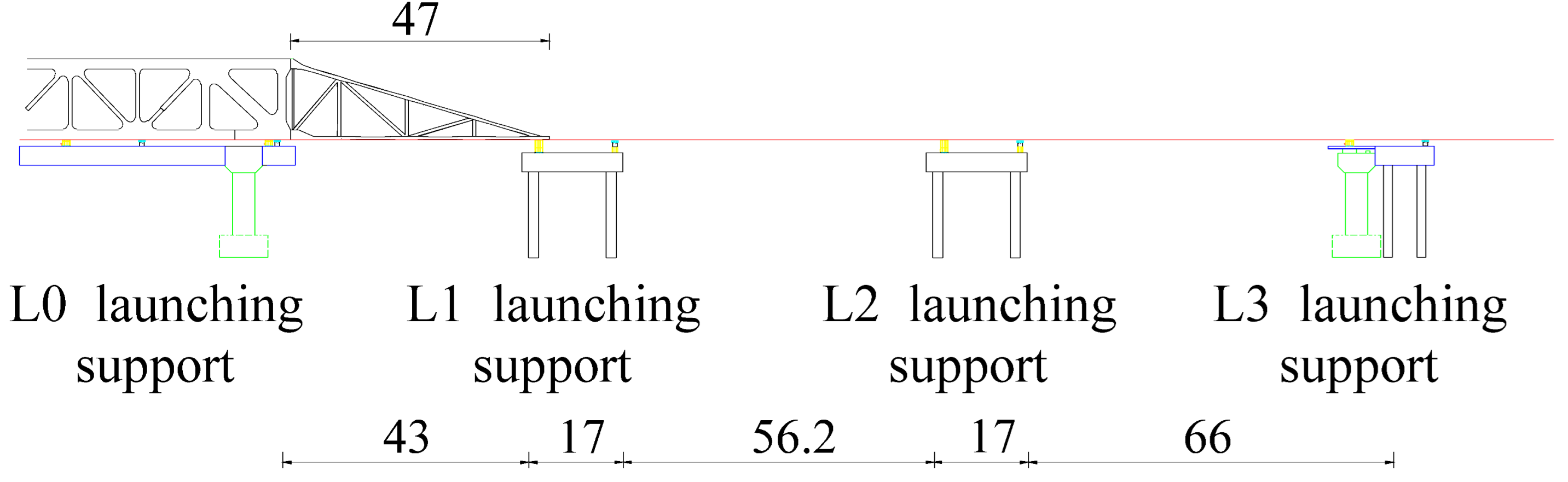 |
| 4–9 | The six trusses were assembled and incrementally launched, with each launch covering a distance of 24.4 m. | 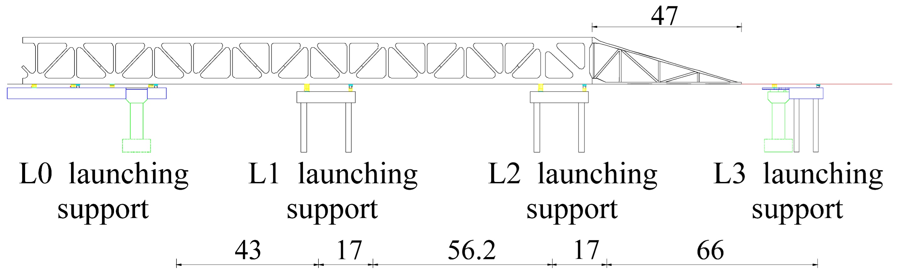 |
| 10–11 | The two trusses were assembled and incrementally launched, with each launch covering a distance of 12.2 m. | 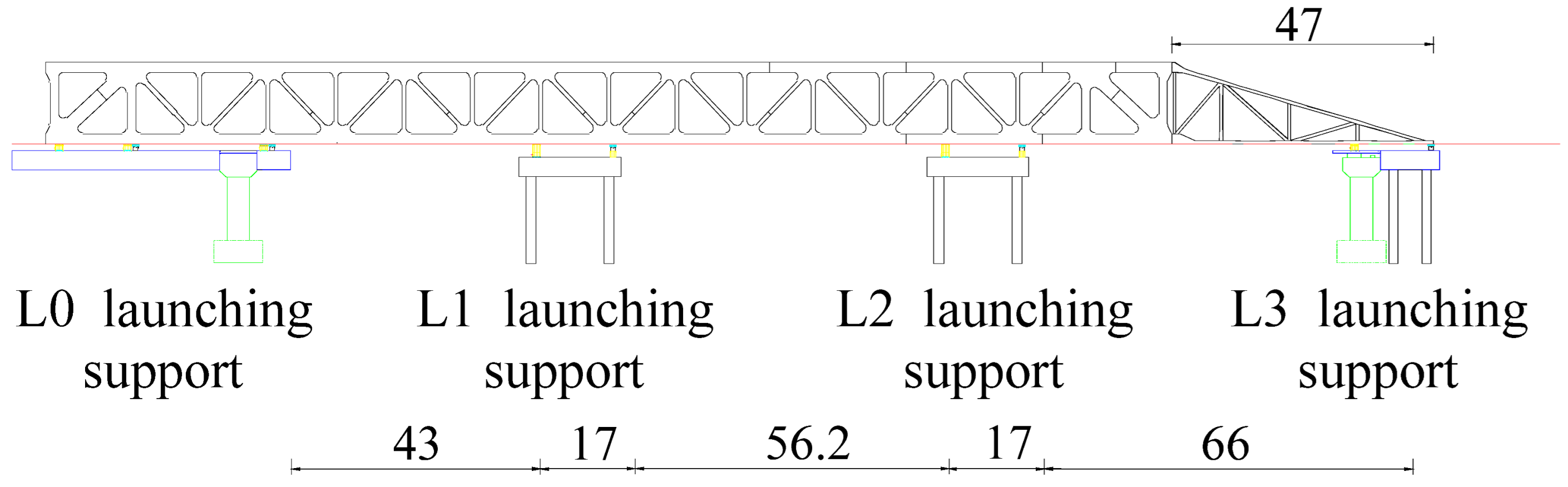 |
| 12 | The steel truss was launched into position (30.3 m). The guide beam was removed, and the permanent supports were installed. | 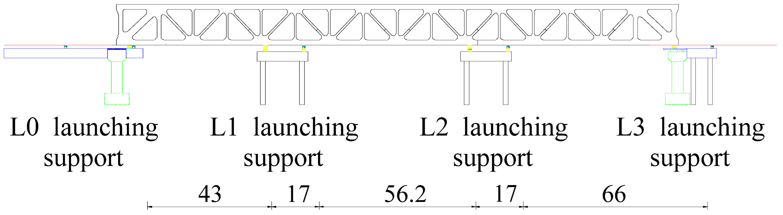 |
| 13 | The arch ribs were installed. | 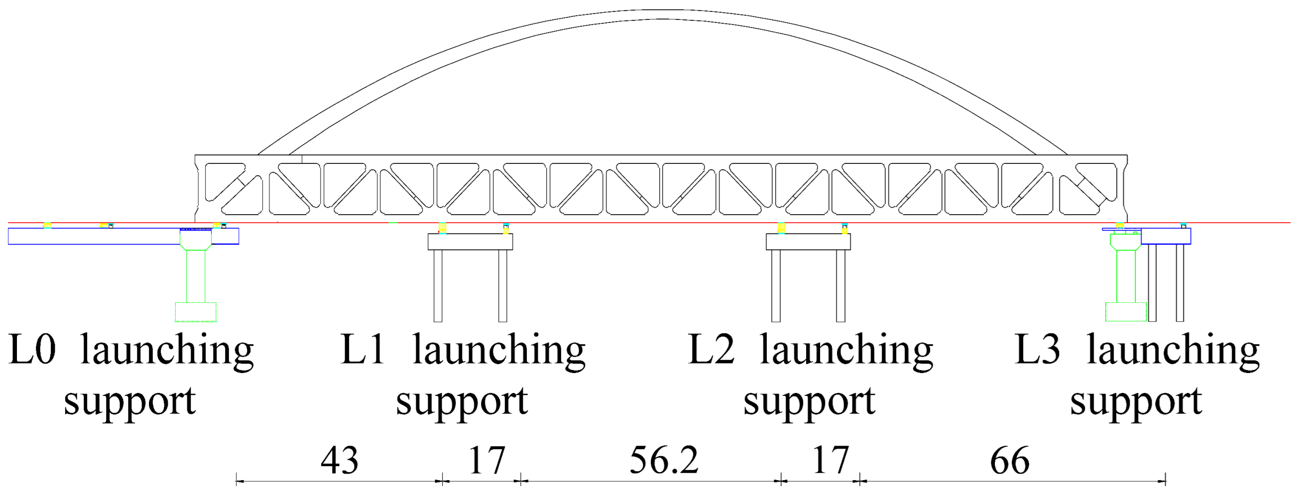 |
| 14–25 | The suspenders were tensioned. |  |
| 26 | Four temporary piers were removed | 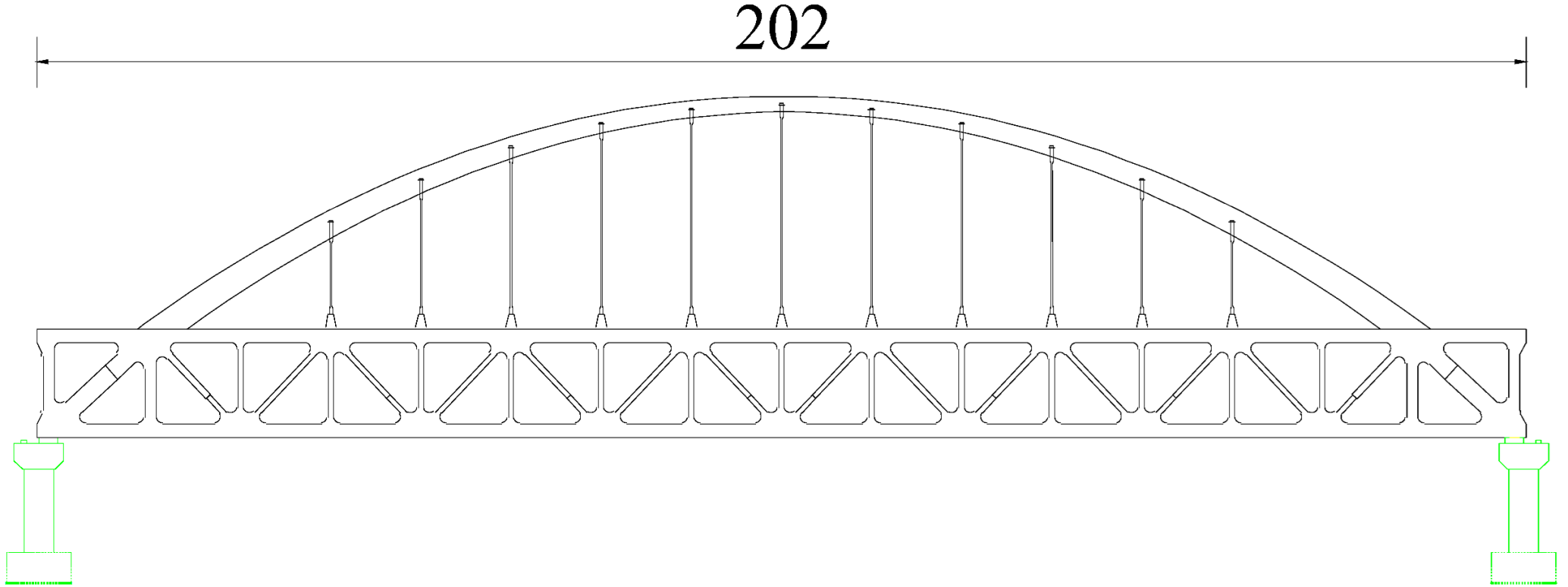 |
| 27 | The bridge deck pavement was installed. | |
| 28 | The forces in some suspenders were adjusted. |
| Measuring Point | Measured Stress/MPa | FE Model Stress/MPa | Relative Difference |
|---|---|---|---|
| 1 | −0.63 | −0.65 | 3.08% |
| 2 | −0.62 | −0.65 | 4.62% |
| 3 | −4.25 | −4.3 | 1.16% |
| 4 | −4.09 | −4.3 | 4.88% |
| Order | Suspenders | Initial Tension | Order | Suspenders | Initial Tension |
|---|---|---|---|---|---|
| 1 | MS6 | 1350 | 7 | LS6, RS6 | 950 |
| 2 | MS5, MS7 | 1850 | 8 | LS5, LS7, RS5, RS7 | 1450 |
| 3 | MS4, MS8 | 1815 | 9 | LS4, LS8, RS4, RS8 | 1415 |
| 4 | MS3, MS9 | 1800 | 10 | LS3, LS9, RS3, RS9 | 1400 |
| 5 | MS2, MS10 | 1700 | 11 | LS2, LS10, RS2, RS10 | 1300 |
| 6 | MS1, MS11 | 1550 | 12 | LS1, LS11, RS1, RS11 | 1150 |
| Critical Members | Axial Force (kN) | Bending Moment (kN·m) |
|---|---|---|
| MD1 | −33,184 | −6218 |
| ML1 | 12,997 | 4920 |
| MU9 | −1999 | 1226 |
| MS5 | 2970 | / |
| Foot in middle arch rib | −31,316 | 9140 |
| End crossbeam | −259.7 | −729 |
Disclaimer/Publisher’s Note: The statements, opinions and data contained in all publications are solely those of the individual author(s) and contributor(s) and not of MDPI and/or the editor(s). MDPI and/or the editor(s) disclaim responsibility for any injury to people or property resulting from any ideas, methods, instructions or products referred to in the content. |
© 2024 by the authors. Licensee MDPI, Basel, Switzerland. This article is an open access article distributed under the terms and conditions of the Creative Commons Attribution (CC BY) license (https://creativecommons.org/licenses/by/4.0/).
Share and Cite
Sun, N.; Zheng, X.; Li, Y.; Zhao, Y.; Yuan, H.; Zhou, M. Numerical Study on the Mechanical Performance of a Flexible Arch Composite Bridge with Steel Truss Beams over Its Entire Lifespan. Sustainability 2024, 16, 6041. https://doi.org/10.3390/su16146041
Sun N, Zheng X, Li Y, Zhao Y, Yuan H, Zhou M. Numerical Study on the Mechanical Performance of a Flexible Arch Composite Bridge with Steel Truss Beams over Its Entire Lifespan. Sustainability. 2024; 16(14):6041. https://doi.org/10.3390/su16146041
Chicago/Turabian StyleSun, Ning, Xiaobo Zheng, Yuan Li, Yunlei Zhao, Haoyun Yuan, and Mi Zhou. 2024. "Numerical Study on the Mechanical Performance of a Flexible Arch Composite Bridge with Steel Truss Beams over Its Entire Lifespan" Sustainability 16, no. 14: 6041. https://doi.org/10.3390/su16146041
APA StyleSun, N., Zheng, X., Li, Y., Zhao, Y., Yuan, H., & Zhou, M. (2024). Numerical Study on the Mechanical Performance of a Flexible Arch Composite Bridge with Steel Truss Beams over Its Entire Lifespan. Sustainability, 16(14), 6041. https://doi.org/10.3390/su16146041