

A Survey on Anomalies and Faults That May Impact the Reliability of Renewable-Based Power Systems
 , , , , , and
Abstract
:1. Introduction
2. Materials and Methods
- In the first phase, anomalies and faults of the components were categorized through a search activity on digital collections such as Scopus, ScienceDirect, Web of Science, and IEEE Xplore, using concatenated keywords related to the component typology (such as “PV” or “Photovoltaic” or “Wind” or “Wind turbine” or “Electrolyzer” or “Electrolysis” or “Fuel Cell” or “FC” or “Battery” or “Battery system” or “BESS” or “Conversion” or “Power conversion” or “Converter” or “AC/DC” or “DC/DC” or “Monitoring systems” or “Communication” or “Communication systems”) and the investigated issue (such as “Failure” or “Anomalies” or “Rupture” or “Degradation” or “Performance decay” or “Reliability” or “Stress test”). The analysis of the identified papers and their related bibliographies was used to extend the investigation to other relevant papers.
- In the second phase, empirical datasets or mathematical models for the identified issues of each technology were searched. Through a detailed analysis of the papers highlighted in the previous phase, useful mathematical models or the existence of dedicated datasets were identified. Datasets were also found using platforms such as Google Dataset Search, IEEE DataPort, Kaggle, and Mendeley Data by using as combined keywords the technology and the investigated issue.
2.1. Caveats
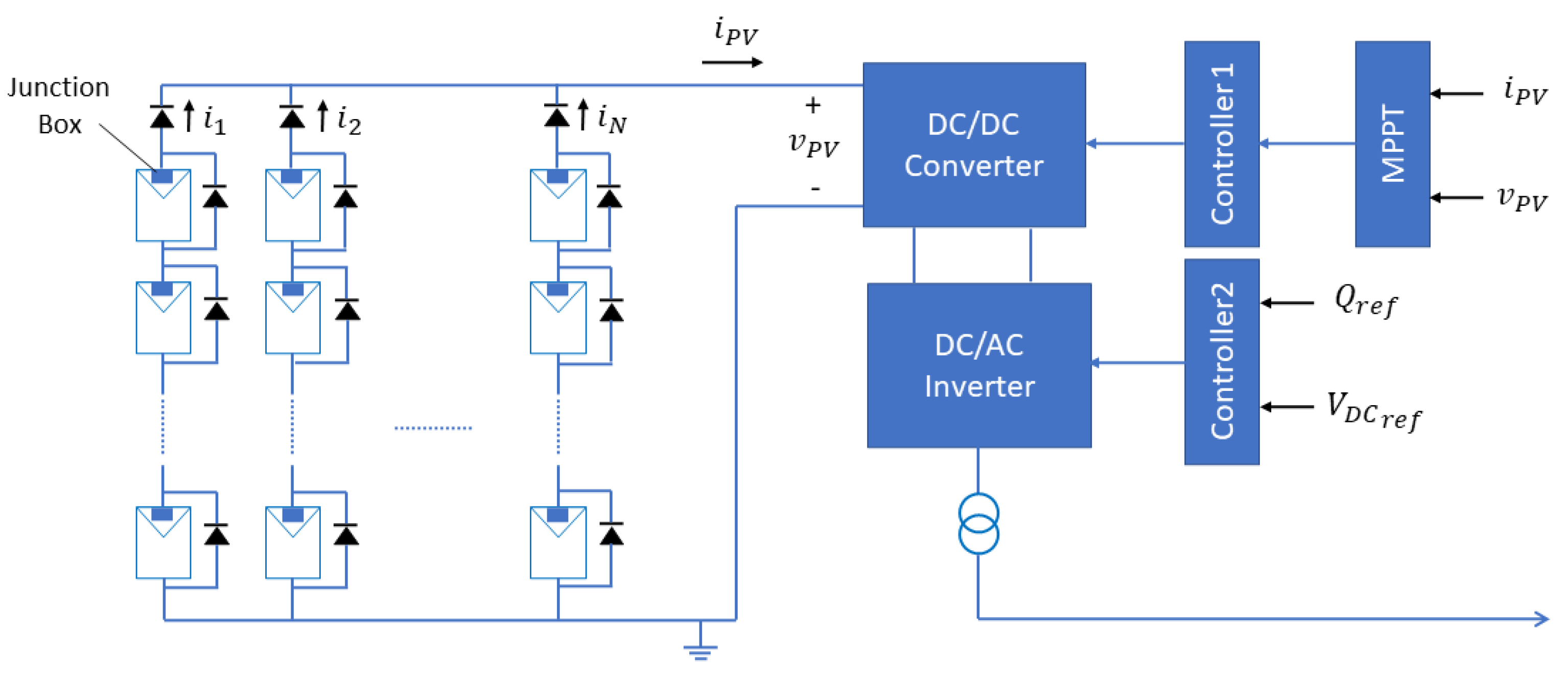
2.2. Anomalies and Faults in PV Systems
Research Highlights
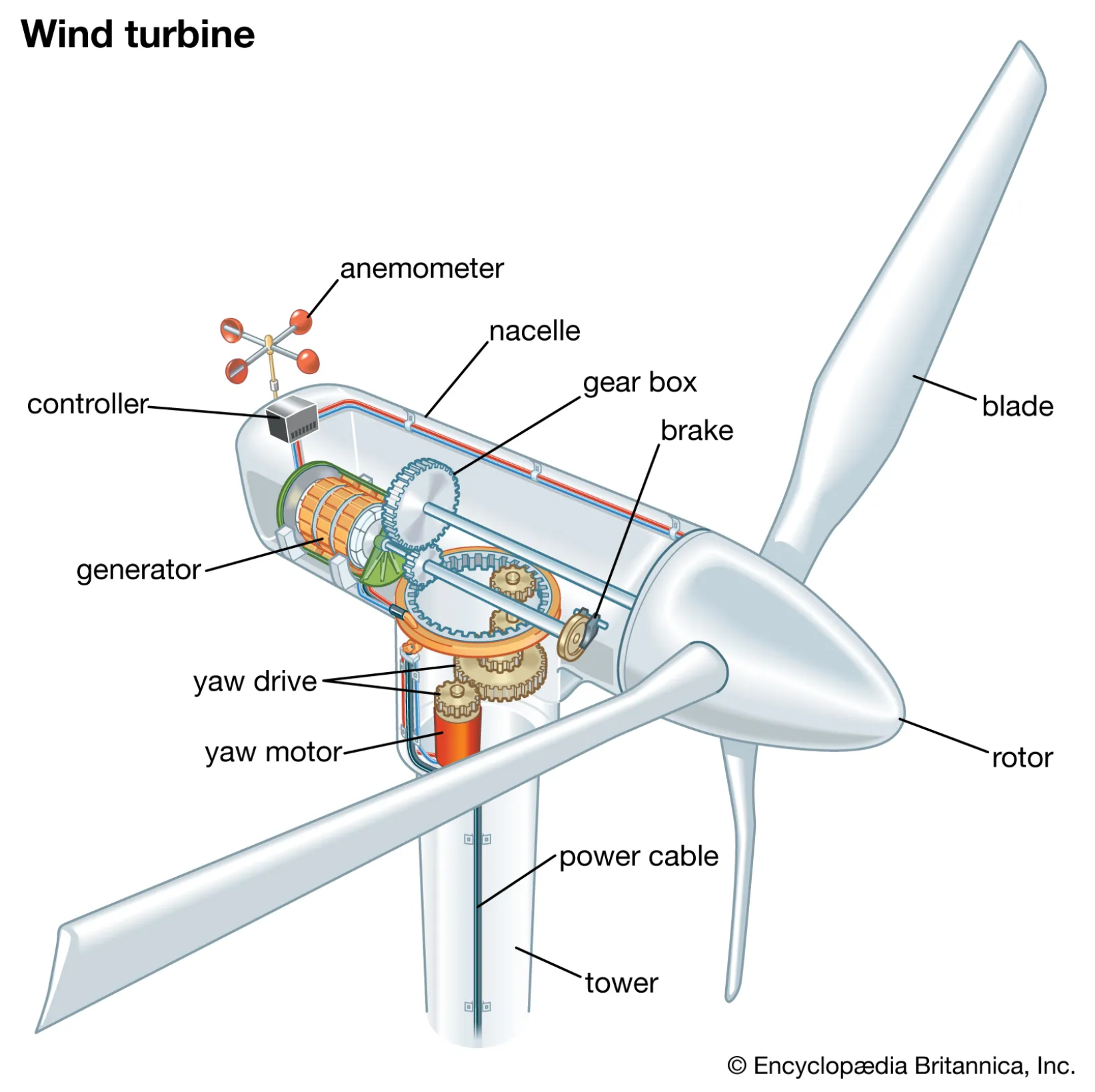
2.3. Anomalies and Faults in Wind Turbines
Research Highlights
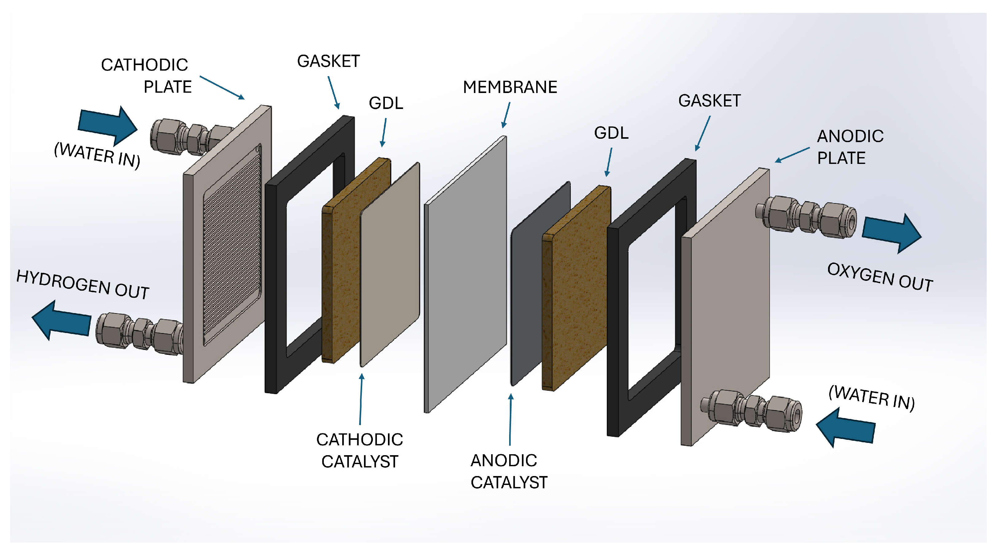
2.4. Anomalies and Faults in Electrolyzers
Research Highlights
2.5. Anomalies and Faults in Fuel Cells
Research Highlights
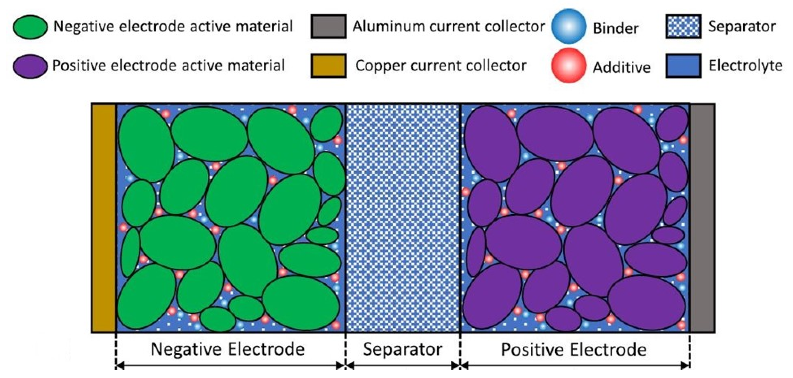
2.6. Anomalies and Faults in Battery Systems
Research Highlights

| Target Component | Description | Cause | References |
|---|---|---|---|
| Cell | Loss of active material | Battery degradation | [127] |
| Electrolyte consumption | [128] | ||
| Increase in internal resistance | [129] | ||
| Lithium deposition | [130] | ||
| Gas generation | [123] | ||
| SEI thickening | [124] | ||
| Current collector corrosion | [131] | ||
| Internal short circuits | [132] | ||
| Thermal runaway | [133] | ||
| Capacity diving | [123] | ||
| Liquid leakage | [123] | ||
| System | Overcharge | Battery management system anomaly/fault | [134] |
| Overdischarge | [135] | ||
| Reduced battery life | [136] | ||
| Thermal runaway | [133] | ||
| Reduced battery performance | Sensory system | [136] | |
| Equalization errors | [123] | ||
| Reduced battery life | [136] | ||
| Thermal runaway accidents | [133] | ||
| Increase internal resistance | Cables and connections | [129] | |
| Thermal runaway safety accidents | [133] |
| Dataset Name | Source | Description | References | Related Papers |
|---|---|---|---|---|
| NASA Data Repository | Lab testing | Data sets suitable to develop algorithms useful as prognostic tools | [138] | |
| IEEE Data Port | Simulations | Data set obtained by simulating a lithium polymer cell model ePLB C020, with an effective capacity of 15 Ah, related an electric car | [139] | |
| Stanford Fast Charging Datasets | Lab testing | Dataset obtained through tests performed on commercial lithium-ion batteries under fast charging conditions. In particular, the cells, of the lithium-iron-phosphate (LFP)/graphite type, produced by A123 Systems (APR18650M1A), were tested on a 48-channel Arbin LBT device. The cells considered are characterized by a nominal capacity of 1.1 Ah and a nominal voltage of 3.3 V | [140] | [141] |
| Lifecycle Prediction Dataset | Lab testing | Data set obtained by testing commercial lithium-ion batteries under fast charging conditions. The lithium-ion phosphate (LFP)/graphite cells, manufactured by A123 Systems (APR18650M1A), were tested using the 48-channel Arbin LBT device in a forced convection temperature chamber set to 30 °C. The cells have a nominal capacity of 1.1 Ah and a nominal voltage of 3.3 V | [142] | [143] |
| University of Wisconsin Madison | Lab testing | Operational dataset for the Panasonic 18650PF lithium-ion battery | [144] | [145] |
| BEEPt | Lab testing | Set of tools designed to support Battery Evaluation and Early Prediction of life cycle corresponding to the research of the d3batt program and the Toyota Research Institute | [146] | [147] |
| Universal Battery Database | Lab testing | Open source Li-ion data management and modelling software | [148] | |
| Alawa-toolbox | Lab testing and simulations | Dataset from University of Hawaii, which provides a large number of curves with different degradation modes, LLI and LAM | [149] | [150] |
2.7. Anomalies and Faults in DC/x Conversion Systems
Research Highlights
2.8. Anomalies and Faults in Monitoring Systems
Research Highlights
2.9. Anomalies and Faults in Communication Systems
Research Highlights
3. Conclusions
Author Contributions
Funding
Data Availability Statement
Conflicts of Interest
Abbreviations
| AI | Artificial Intelligence |
| BS | Battery System |
| EIS | Electrochemical Impedance Spectrometry |
| FC | Fuel Cell |
| GDL | Gas Distribution Layer |
| HAWT | Horizontal-Axis Wind Turbine |
| IGBT | Insulated-Gate Bipolar Transistor |
| LAM | Loss of Active Material |
| Li-ion | Lithium-ion |
| LLI | Loss of Lithyum Inventory |
| ML | Machine Learning |
| MOSFET | Metal–Oxide–Semiconductor Field-Effect Transistor |
| MPPT | Maximum Power Point Tracking |
| PEM | Polymeric Electrolyte Membrane |
| PV | Photo Voltaic |
| PWM | Pulse-Width Modulation/Modulated |
| SEI | Solid Electrolyte Interphase |
| STC | Standard Test Condition |
| VAWT | Vertical-Axis Wind Turbine |
| WT | Wind Turbine |
References
- Ren, B.; Chi, Y.; Zhou, N.; Wang, Q.; Wang, T.; Luo, Y.; Ye, J.; Zhu, X. Machine learning applications in health monitoring of renewable energy systems. Renew. Sustain. Energy Rev. 2024, 189, 114039. [Google Scholar] [CrossRef]
- Afridi, Y.S.; Ahmad, K.; Hassan, L. Artificial intelligence based prognostic maintenance of renewable energy systems: A review of techniques, challenges, and future research directions. Int. J. Energy Res. 2022, 46, 21619–21642. [Google Scholar] [CrossRef]
- Ibrahim, M.S.; Dong, W.; Yang, Q. Machine learning driven smart electric power systems: Current trends and new perspectives. Appl. Energy 2020, 272, 115237. [Google Scholar] [CrossRef]
- Tuyen, N.D.; Quan, N.S.; Linh, V.B.; Van Tuyen, V.; Fujita, G. A Comprehensive Review of Cybersecurity in Inverter-Based Smart Power System Amid the Boom of Renewable Energy. IEEE Access 2022, 10, 35846–35875. [Google Scholar] [CrossRef]
- Hare, J.; Shi, X.; Gupta, S.; Bazzi, A. Fault diagnostics in smart micro-grids: A survey. Renew. Sustain. Energy Rev. 2016, 60, 1114–1124. [Google Scholar] [CrossRef]
- Hare, J.; Shi, X.; Gupta, S.; Bazzi, A. A review of faults and fault diagnosis in micro-grids electrical energy infrastructure. In Proceedings of the 2014 IEEE Energy Conversion Congress and Exposition (ECCE), Pittsburgh, PA, USA, 14–18 September 2014; pp. 3325–3332. [Google Scholar] [CrossRef]
- Labrador Rivas, A.E.; Abrão, T. Faults in smart grid systems: Monitoring, detection and classification. Electr. Power Syst. Res. 2020, 189, 106602. [Google Scholar] [CrossRef]
- Jaen-Cuellar, A.Y.; Elvira-Ortiz, D.A.; Osornio-Rios, R.A.; Antonino-Daviu, J.A. Advances in Fault Condition Monitoring for Solar Photovoltaic and Wind Turbine Energy Generation: A Review. Energies 2022, 15, 5404. [Google Scholar] [CrossRef]
- Neumayer, M.; Stecher, D.; Grimm, S.; Maier, A.; Bücker, D.; Schmidt, J. Fault and anomaly detection in district heating substations: A survey on methodology and data sets. Energy 2023, 276, 127569. [Google Scholar] [CrossRef]
- Gururajapathy, S.S.; Mokhlis, H.; Illias, H.A. Fault location and detection techniques in power distribution systems with distributed generation: A review. Renew. Sustain. Energy Rev. 2017, 74, 949–958. [Google Scholar] [CrossRef]
- IEEE Std 1044-2009; IEEE Standard Classification for Software Anomalies. IEEE: Piscataway, NJ, USA,, 2010; pp. 1–23. [CrossRef]
- NASA SP-2016-6105; NASA Systems Engineering Handbook. NASA—National Aeronautics and Space Administration: Washington, DC, USA, 2016.
- Avizienis, A.; Laprie, J.C.; Randell, B.; Landwehr, C. Basic concepts and taxonomy of dependable and secure computing. IEEE Trans. Dependable Secur. Comput. 2004, 1, 11–33. [Google Scholar] [CrossRef]
- Tipton, C.I.W. Survey of Fault Detection and Classification in Power Conversion Electronics; Technical Report AD1115443; DEVCOM Army Research Laboratory: Adelphi, NY, USA, 2020; Available online: https://apps.dtic.mil/sti/citations/AD1115443 (accessed on 9 May 2024).
- Hong, Y.Y.; Pula, R.A. Methods of photovoltaic fault detection and classification: A review. Energy Rep. 2022, 8, 5898–5929. [Google Scholar] [CrossRef]
- Osmani, K.; Haddad, A.; Lemenand, T.; Castanier, B.; Alkhedher, M.; Ramadan, M. A critical review of PV systems’ faults with the relevant detection methods. Energy Nexus 2023, 12, 100257. [Google Scholar] [CrossRef]
- Jiang, L.; Maskell, D. Automatic fault detection and diagnosis for photovoltaic systems using combined artificial neural network and analytical based methods. In Proceedings of the 2015 International Joint Conference on Neural Networks (IJCNN), Killarney, UK, 12–17 July 2015; pp. 1–8. [Google Scholar] [CrossRef]
- Chine, W.; Mellit, A.; Pavan, A.; Lughi, V. Fault diagnosis in photovoltaic arrays. In Proceedings of the 2015 International Conference on Clean Electrical Power, Taormina, Italy, 16–18 June 2015; pp. 67–72. [Google Scholar] [CrossRef]
- Kumar, S.S.; Selvakumar, A.I. Detection of the faults in the photovoltaic array under normal and partial shading conditions. In Proceedings of the 2017 Innovations in Power and Advanced Computing Technologies (i-PACT), Vellore, India, 21–22 April 2017; pp. 1–5. [Google Scholar] [CrossRef]
- Buonanno, A.; Caputo, G.; Balog, I.; Fabozzi, S.; Adinolfi, G.; Pascarella, F.; Leanza, G.; Graditi, G.; Valenti, M. Machine Learning and Weather Model Combination for PV Production Forecasting. Energies 2024, 17, 2203. [Google Scholar] [CrossRef]
- Buonanno, A.; Caliano, M.; Di Somma, M.; Graditi, G.; Valenti, M. A Comprehensive Tool for Scenario Generation of Solar Irradiance Profiles. Energies 2022, 15, 8830. [Google Scholar] [CrossRef]
- Nguyen, X.H. Matlab/Simulink Based Modeling to Study Effect of Partial Shadow on Solar Photovoltaic Array. Environ. Syst. Res. 2015, 4, 20. [Google Scholar] [CrossRef]
- Hu, Y.; Cao, W.; Ma, J.; Finney, S.J.; Li, D. Identifying PV Module Mismatch Faults by a Thermography-Based Temperature Distribution Analysis. IEEE Trans. Device Mater. Reliab. 2014, 14, 951–960. [Google Scholar] [CrossRef]
- Li, X.; Yang, Q.; Lou, Z.; Yan, W. Deep Learning Based Module Defect Analysis for Large-Scale Photovoltaic Farms. IEEE Trans. Energy Convers. 2019, 34, 520–529. [Google Scholar] [CrossRef]
- Mustafa, R.J.; Gomaa, M.R.; Al-Dhaifallah, M.; Rezk, H. Environmental Impacts on the Performance of Solar Photovoltaic Systems. Sustainability 2020, 12, 608. [Google Scholar] [CrossRef]
- Hetita, I.; Zalhaf, A.S.; Mansour, D.E.A.; Han, Y.; Yang, P.; Wang, C. Modeling and Protection of Photovoltaic Systems During Lightning Strikes: A Review. Renew. Energy 2022, 184, 134–148. [Google Scholar] [CrossRef]
- Köntges, M.; Kurtz, S.; Packard, C.; Jahn, U.; Berger, K.A.; Kato, K.; Friesen, T.; Liu, H.; Van Iseghem, M. Review of Failures of Photovoltaic Modules; Report T13-01:2014; IEA-PVPS: Redfern, NSW, Australia, 2014; Available online: https://iea-pvps.org/key-topics/review-of-failures-of-photovoltaic-modules-final/ (accessed on 10 July 2024).
- Itoh, U.; Yoshida, M.; Tokuhisa, H.; Takeuchi, K.; Takemura, Y. Solder Joint Failure Modes in the Conventional Crystalline Si Module. Energy Procedia 2014, 55, 464–468. [Google Scholar] [CrossRef]
- Alam, M.K.; Khan, F.; Johnson, J.; Flicker, J. A Comprehensive Review of Catastrophic Faults in PV Arrays: Types, Detection, and Mitigation Techniques. IEEE J. Photovolt. 2015, 5, 982–997. [Google Scholar] [CrossRef]
- Zhao, Y. Fault Analysis in Solar Photovoltaic Arrays. Master’s Thesis, Northeastern University, Boston, MA, USA, 2010. [Google Scholar]
- Badr, M.M.; Hamad, M.S.; Abdel-Khalik, A.S.; Hamdy, R.A. Fault Detection and Diagnosis for Photovoltaic Array Under Grid Connected Using Support Vector Machine. In Proceedings of the 2019 IEEE Conference on Power Electronics and Renewable Energy (CPERE), Aswan City, Egypt, 23–25 October 2019; pp. 546–553. [Google Scholar] [CrossRef]
- Chan, F.; Calleja, H. Reliability: A New Approach in Design of Inverters for PV Systems. In Proceedings of the 2006 IEEE International Power Electronics Congress, Puebla, Mexico, 16–18 October 2006; pp. 1–6. [Google Scholar] [CrossRef]
- Ma, M.; Liu, H.; Zhang, Z.; Yun, P.; Liu, F. Rapid diagnosis of hot spot failure of crystalline silicon PV module based on I-V curve. Microelectron. Reliab. 2019, 100–101, 113402. [Google Scholar] [CrossRef]
- Bdour, M.; Dalala, Z.; Al-Addous, M.; Radaideh, A.; Al-Sadi, A. A comprehensive evaluation on types of microcracks and possible effects on power degradation in photovoltaic solar panels. Sustainability 2020, 12, 6416. [Google Scholar] [CrossRef]
- Colvin, D.J.; Schneller, E.J.; Davis, K.O. Impact of Interconnection Failure on Photovoltaic Module Performance. Prog. Photovoltaics Res. Appl. 2021, 29, 524–532. [Google Scholar] [CrossRef]
- Kim, J.; Rabelo, M.; Padi, S.; Yousuf, H.; Cho, E.C.; Yi, J. A review of the degradation of photovoltaic modules for life expectancy. Energies 2021, 14, 4278. [Google Scholar] [CrossRef]
- Bouaichi, A.; Merrouni, A.; El Hassani, A.; Naimi, Z.; Ikken, B.; Ghennioui, A.; Benazzouz, A.; El Amrani, A.; Messaoudi, C. Experimental evaluation of the discoloration effect on PV-modules performance drop. Energy Procedia 2017, 119, 818–827. [Google Scholar] [CrossRef]
- Hasan, A.A.; Ahmed Alkahtani, A.; Shahahmadi, S.A.; Nur, E.; Alam, M.; Islam, M.A.; Amin, N. Delamination and Electromigration-Related Failures in Solar Panels – A Review. Sustainability 2021, 13, 6882. [Google Scholar] [CrossRef]
- Popovich, V. Breakage issues in silicon solar wafers and cells. Photovoltaics Int. 2011, 12, 49–57. [Google Scholar]
- Kalejs, J. Junction Box Wiring and Connector Durability Issues in Photovoltaic Modules. In Proceedings of the International Society for Optical Engineering (SPIE), San Francisco, CA, USA, 2–5 February 2014; SPIE: Bellingham, WA, USA, 2014; Volume 9179, p. 91790S. [Google Scholar] [CrossRef]
- National Academies of Sciences, Engineering, and Medicine. Enhancing the Resilience of the Nation’s Electricity System; The National Academies Press: Washington, DC, USA, 2017. [Google Scholar] [CrossRef]
- Ghoneim, S.S.M.; Rashed, A.E.; Elkalashy, N.I. Fault Detection Dataset in Photovoltaic Farms. 2020. Available online: https://www.kaggle.com/datasets/amrezzeldinrashed/fault-detection-dataset-in-photovoltaic-farms (accessed on 12 January 2024).
- Ghoneim, S.S.M.; Rashed, A.E.; Elkalashy, N.I. Fault Detection Algorithms for Achieving Service Continuity in Photovoltaic Farms. Intell. Autom. Soft Comput. 2021, 30, 467–479. [Google Scholar] [CrossRef]
- Su, B.; Zhou, Z.; Chen, H. Photovoltaic Cell Aanomaly Detection Dataset. 2022. Available online: https://ieee-dataport.org/documents/photovoltaic-cell-anomaly-detection-dataset (accessed on 12 January 2024).
- Su, B.; Zhou, Z.; Chen, H. PVEL-AD: A Large-Scale Open-World Dataset for Photovoltaic Cell Anomaly Detection. IEEE Trans. Ind. Inform. 2023, 19, 404–413. [Google Scholar] [CrossRef]
- Bakdi, A.; Bounoua, W.; Guichi, A.; Mekhilef, S. GPVS-Faults: Experimental Data for Fault Scenarios in Grid-Connected PV Systems under MPPT and IPPT Modes. 2020. Available online: https://data.mendeley.com/datasets/n76t439f65/1 (accessed on 12 January 2024).
- Bakdi, A.; Bounoua, W.; Guichi, A.; Mekhilef, S. Real-time fault detection in PV systems under MPPT using PMU and high-frequency multi-sensor data through online PCA-KDE-based multivariate KL divergence. Int. J. Electr. Power Energy Syst. 2021, 125, 106457. [Google Scholar] [CrossRef]
- Wang, Q.; Paynabar, K.; Pacella, M. Online Automatic Anomaly Detection for Photovoltaic Systems Using Thermography Imaging and Low Rank Matrix Decomposition (Dataset). 2021. Available online: https://tandf.figshare.com/articles/dataset/Online_automatic_anomaly_detection_for_photovoltaic_systems_using_thermography_imaging_and_low_rank_matrix_decomposition/15123655/1 (accessed on 12 January 2024).
- Wang, Q.; Paynabar, K.; Pacella, M. Online automatic anomaly detection for photovoltaic systems using thermography imaging and low rank matrix decomposition. J. Qual. Technol. 2022, 54, 503–516. [Google Scholar] [CrossRef]
- Gabriel, M. Photovoltaic System Thermography. 2023. Available online: https://www.kaggle.com/datasets/marcosgabriel/photovoltaic-system-thermography (accessed on 12 January 2024).
- Piliougine, M.; Spagnuolo, G. Mismatching and Partial Shading Identification in Photovoltaic Arrays by an Artificial Neural Network Ensemble (Dataset). 2022. Available online: https://zenodo.org/record/4781151 (accessed on 12 January 2024).
- Piliougine, M.; Spagnuolo, G. Mismatching and partial shading identification in photovoltaic arrays by an artificial neural network ensemble. Solar Energy 2022, 236, 712–723. [Google Scholar] [CrossRef]
- Sood, K.; Ruppert, N.; Mahto, R. Partial Shading and Fault Simulation Dataset of Photovoltaics Module. 2022. Available online: https://ieee-dataport.org/documents/partial-shading-and-fault-simulation-dataset-photovoltaics-module(accessed on 12 January 2024).
- Lazzaretti, A.E.; Costa, C.H.d.; Rodrigues, M.P.; Yamada, G.D.; Lexinoski, G.; Moritz, G.L.; Oroski, E.; Goes, R.E.d.; Linhares, R.R.; Stadzisz, P.C.; et al. A Monitoring System for Online Fault Detection and Classification in Photovoltaic Plants (dataset). 2020. Available online: https://github.com/clayton-h-costa/pv_fault_dataset (accessed on 12 January 2024).
- Lazzaretti, A.E.; Costa, C.H.d.; Rodrigues, M.P.; Yamada, G.D.; Lexinoski, G.; Moritz, G.L.; Oroski, E.; Goes, R.E.d.; Linhares, R.R.; Stadzisz, P.C.; et al. A Monitoring System for Online Fault Detection and Classification in Photovoltaic Plants. Sensors 2020, 20, 4688. [Google Scholar] [CrossRef]
- ELPV-Dataset. 2018. Available online: https://github.com/zae-bayern/elpv-dataset (accessed on 12 January 2024).
- Buerhop-Lutz, C.; Deitsch, S.; Maier, A.; Gallwitz, F.; Berger, S.; Doll, B.; Hauch, J.; Camus, C.; Brabec, C.J. A Benchmark for Visual Identification of Defective Solar Cells in Electroluminescence Imagery. In Proceedings of the European PV Solar Energy Conference and Exhibition (EU PVSEC), Brussels, Belgium, 24–28 September 2018. [Google Scholar] [CrossRef]
- Deitsch, S.; Christlein, V.; Berger, S.; Buerhop-Lutz, C.; Maier, A.; Gallwitz, F.; Riess, C. Automatic classification of defective photovoltaic module cells in electroluminescence images. Solar Energy 2019, 185, 455–468. [Google Scholar] [CrossRef]
- Deitsch, S.; Buerhop-Lutz, C.; Sovetkin, E.; Steland, A.; Maier, A.; Gallwitz, F.; Riess, C. Segmentation of photovoltaic module cells in uncalibrated electroluminescence images. Mach. Vis. Appl. 2021, 32, 84. [Google Scholar] [CrossRef]
- NREL—National Renewable Energy Laboratory, U.S.; Department of Energy, Office of Energy Efficiency and Renewable Energy. PVWatts Calculator. Available online: https://pvwatts.nrel.gov/pvwatts.php (accessed on 12 January 2024).
- Badurek, C.A.; Wind Turbine. Encyclopedia Britannica. Available online: https://www.britannica.com/technology/wind-turbine. (accessed on 11 March 2024).
- Dao, C.; Kazemtabrizi, B.; Crabtree, C. Wind turbine reliability data review and impacts on levelised cost of energy. Wind Energy 2019, 22, 1848–1871. [Google Scholar] [CrossRef]
- Sivankutty, S.; Mary, S.A.J. Fault Diagnosis and Control Techniques for Wind Energy Conversion System: A Systematic Review. In Proceedings of the 2022 Third International Conference on Intelligent Computing Instrumentation and Control Technologies (ICICICT), Kannur, India, 11–12 August 2022; pp. 700–704. [Google Scholar] [CrossRef]
- Liu, W.Y.; Gu, H.; Gao, Q.W.; Zhang, Y. A review on wind turbines gearbox fault diagnosis methods. J. Vibroeng. 2021, 23, 26–43. [Google Scholar] [CrossRef]
- Sheng, S. Wind Turbine Gearbox Condition Monitoring Vibration Analysis Benchmarking Datasets. 2014. Available online: https://data.openei.org/submissions/738 (accessed on 10 July 2024).
- Ogaili, A.A.F.; Abdulhady, J.A.; Hamzah, M.N. Wind Turbine Blades Fault Diagnosis Based on Vibration Dataset Analysis. 2023. Available online: https://data.mendeley.com/datasets/5d7vbdp8f7/4 (accessed on 12 January 2024).
- Ogaili, A.A.F.; Abdulhady, J.A. Vibration Signals Feature for Fault Diagnosis of Wind Turbine Blade. 2023. Available online: https://data.mendeley.com/datasets/2kx995rscj/2 (accessed on 12 January 2024).
- Foster, A.; Best, O.; Gianni, M.; Khan, A.; Collins, K.; Sharma, S. YOLO Annotated Wind Turbine Surface Damage. 2021. Available online: https://www.kaggle.com/datasets/ajifoster3/yolo-annotated-wind-turbines-586x371 (accessed on 12 January 2024).
- Foster, A.; Best, O.; Gianni, M.; Khan, A.; Collins, K.; Sharma, S. Drone Footage Wind Turbine Surface Damage Detection. In Proceedings of the 2022 IEEE 14th Image, Video, and Multidimensional Signal Processing Workshop (IVMSP), Nafplio, Greece, 26–29 June 2022; pp. 1–5. [Google Scholar] [CrossRef]
- Xiaoqiang, W.; Ziang, X. Data for: Wind turbine fault diagnosis based on ReliefF-PCA and DNN. 2021. Available online: https://data.mendeley.com/datasets/v9wnr4bft9/1 (accessed on 12 January 2024).
- Wen, X.; Xu, Z. Wind turbine fault diagnosis based on ReliefF-PCA and DNN. Expert Syst. Appl. 2021, 178, 115016. [Google Scholar] [CrossRef]
- Sá, B.A.; Barros, C.M.V.; Siebra, C.A.; Barros, L.S. Wind Turbine PMSG-Short-Circuit Fault. 2019. Available online: https://www.kaggle.com/datasets/brunoadonis/wind-turbine-pmsg-short-circuit-fault-mcsa (accessed on 12 January 2024).
- Sá, B.A.; Barros, C.M.V.; Siebra, C.A.; Barros, L.S. A Multilayer Perceptron-Based Approach for Stator Fault Detection in Permanent Magnet Wind Generators. In Proceedings of the 2019 IEEE PES Innovative Smart Grid Technologies Conference—Latin America (ISGT Latin America), Gramado, Brazil, 15–18 September 2019; pp. 1–6. [Google Scholar] [CrossRef]
- Wonho, J.; Seong-Hu, K.; Sung-Hyun, Y.; Jaewoong, B.; Yong-Hwa, P. Vibration and Motor Current Dataset of Rolling Element Bearing Under Varying Speed Conditions for Fault Diagnosis: Subset1. Available online: https://data.mendeley.com/datasets/vxkj334rzv/7 (accessed on 12 January 2024).
- Wonho, J.; Seong-Hu, K.; Sung-Hyun, Y.; Jaewoong, B.; Yong-Hwa, P. Vibration and Motor Current Dataset of Rolling Element Bearing Under Varying Speed Conditions for Fault Diagnosis: Subset2. Available online: https://data.mendeley.com/datasets/x3vhp8t6hg/7 (accessed on 12 January 2024).
- Wonho, J.; Seong-Hu, K.; Sung-Hyun, Y.; Jaewoong, B.; Yong-Hwa, P. Vibration and Motor Current Dataset of Rolling Element Bearing Under Varying Speed Conditions for Fault Diagnosis: Subset3. Available online: https://data.mendeley.com/datasets/j8d8pfkvj2/7 (accessed on 12 January 2024).
- Wonho, J.; Seong-Hu, K.; Sung-Hyun, Y.; Jaewoong, B.; Yong-Hwa, P. Vibration, acoustic, temperature, and motor current dataset of rotating machine under varying operating conditions for fault diagnosis. Data Brief 2023, 48, 109049. [Google Scholar] [CrossRef]
- Pandya, Y. Gearbox Fault Diagnosis Data. 2018. Available online: https://data.openei.org/submissions/623 (accessed on 12 January 2024).
- de Portugal, E.E. EDP Open Data. Available online: https://www.edp.com/en/innovation/open-data/data. (accessed on 12 January 2024).
- Kheirrouz, M.; Melino, F.; Ancona, M.A. Fault detection and diagnosis methods for green hydrogen production: A review. Int. J. Hydrogen Energy 2022, 47, 27747–27774. [Google Scholar] [CrossRef]
- Kokoh, K.B.; Mayousse, E.; Napporn, T.W.; Servat, K.; Guillet, N.; Soyez, E.; Grosjean, A.; Rakotondrainibé, A.; Paul-Joseph, J. Efficient multi-metallic anode catalysts in a PEM water electrolyzer. Int. J. Hydrogen Energy 2014, 39, 1924–1931. [Google Scholar] [CrossRef]
- Yu, H.; Bonville, L.; Jankovic, J.; Maric, R. Microscopic insights on the degradation of a PEM water electrolyzer with ultra-low catalyst loading. Appl. Catal. Environ. 2020, 260, 118194. [Google Scholar] [CrossRef]
- Zhang, S.; Yuan, X.; Wang, H.; Merida, W.; Zhu, H.; Shen, J.; Wu, S.; Zhang, J. A review of accelerated stress tests of MEA durability in PEM fuel cells. Int. J. Hydrogen Energy 2009, 34, 388–404. [Google Scholar] [CrossRef]
- Siracusano, S.; Baglio, V.; Van Dijk, N.; Merlo, L.; Aricò, A. Enhanced performance and durability of low catalyst loading PEM water electrolyser based on a short-side chain perfluorosulfonic ionomer. Appl. Energy 2017, 192, 477–489. [Google Scholar] [CrossRef]
- Millet, P.; Ranjbari, A.; De Guglielmo, F.; Grigoriev, S.A.; Auprêtre, F. Cell failure mechanisms in PEM water electrolyzers. Int. J. Hydrogen Energy 2012, 37, 17478–17487. [Google Scholar] [CrossRef]
- Grigoriev, S.A.; Dzhus, K.A.; Bessarabov, D.G.; Millet, P. Failure of PEM water electrolysis cells: Case study involving anode dissolution and membrane thinning. Int. J. Hydrogen Energy 2014, 39, 20440–20446. [Google Scholar] [CrossRef]
- Chandesris, M.; Médeau, V.; Guillet, N.; Chelghoum, S.; Thoby, D.; Fouda-Onana, F. Numerical modelling of membrane degradation in PEM water electrolyzer: Influence of the temperature and current density. In Proceedings of the 6th International Conference on Fundamentals and Development of Fuel Cells, FDFC2015, Toulouse, France, 3–5 February 2015. [Google Scholar]
- Kuhnert, E.; Heidinger, M.; Sandu, D.; Hacker, V.; Bodner, M. Analysis of PEM Water Electrolyzer Failure Due to Induced Hydrogen Crossover in Catalyst-Coated PFSA Membranes. Membranes 2023, 13, 348. [Google Scholar] [CrossRef] [PubMed]
- Li, N.; Araya, S.S.; Kær, S.K. Investigating low and high load cycling tests as accelerated stress tests for proton exchange membrane water electrolysis. Electrochim. Acta 2021, 370, 137748. [Google Scholar] [CrossRef]
- Spöri, C.; Kwan, J.T.H.; Bonakdarpour, A.; Wilkinson, D.P.; Strasser, P. The Stability Challenges of Oxygen Evolving Catalysts: Towards a Common Fundamental Understanding and Mitigation of Catalyst Degradation. Angew. Chem. Int. Ed. 2017, 56, 5994–6021. [Google Scholar] [CrossRef]
- Renda, S.; Ricca, A.; Palma, V. Precursor salts influence in Ruthenium catalysts for CO2 hydrogenation to methane. Appl. Energy 2020, 279, 115767. [Google Scholar] [CrossRef]
- Hu, Y.; Xu, X.; Wang, W. A new cavity profile for a diaphragm compressor used in hydrogen fueling stations. Int. J. Hydrogen Energy 2017, 42, 24458–24469. [Google Scholar] [CrossRef]
- Ghaedamini, M.; Baharlou-Houreh, N.; Afshari, E.; Shokouhmand, H.; Jahantigh, N. Experimental investigation on the heat and water transfer enhancement in a membrane-based air-to-air humidifier at insulation condition. Int. J. Hydrogen Energy 2022, 47, 17010–17021. [Google Scholar] [CrossRef]
- Carmo, M.; Fritz, D.L.; Mergel, J.; Stolten, D. A comprehensive review on PEM water electrolysis. Int. J. Hydrogen Energy 2013, 38, 4901–4934. [Google Scholar] [CrossRef]
- Choi, S.R.; Lim, M.; Kim, D.Y.; An, W.Y.; Lee, S.W.; Choi, S.; Bae, S.J.; Yim, S.D.; Park, J.Y. Life prediction of membrane electrode assembly through load and potential cycling accelerated degradation testing in polymer electrolyte membrane fuel cells. Int. J. Hydrogen Energy 2022, 47, 17379–17392. [Google Scholar] [CrossRef]
- Singh, Y.; Orfino, F.; Dutta, M.; Kjeang, E. 3D Failure Analysis of Pure Mechanical and Pure Chemical Degradation in Fuel Cell Membranes. J. Electrochem. Soc. 2017, 164, F1331–F1341. [Google Scholar] [CrossRef]
- Alavijeh, A.S.; Bhattacharya, S.; Thomas, O.; Chuy, C.; Yang, Y.; Zhang, H.; Kjeang, E. Effect of hygral swelling and shrinkage on mechanical durability of fuel cell membranes. J. Power Sources 2019, 427, 207–214. [Google Scholar] [CrossRef]
- Panha, K.; Fowler, M.; Yuan, X.Z.; Wang, H. Accelerated durability testing via reactants relative humidity cycling on PEM fuel cells. Appl. Energy 2012, 93, 90–97. [Google Scholar] [CrossRef]
- Yuan, X.Z.; Zhang, S.; Ban, S.; Huang, C.; Wang, H.; Singara, V.; Fowler, M.; Schulze, M.; Haug, A.; Friedrich, K.A.; et al. Degradation of a PEM fuel cell stack with Nafion® membranes of different thicknesses. Part II: Ex situ diagnosis. J. Power Sources 2012, 205, 324–334. [Google Scholar] [CrossRef]
- Healy, J.; Hayden, C.; Xie, T.; Olson, K.; Waldo, R.; Brundage, M.; Gasteiger, H.; Abbott, J. Aspects of the chemical degradation of PFSA ionomers used in PEM fuel cellsx. Fuel Cells 2005, 5, 302–308. [Google Scholar] [CrossRef]
- Shi, S.; Sun, X.; Lin, Q.; Chen, J.; Fu, Y.; Hong, X.; Li, C.; Guo, X.; Chen, G.; Chen, X. Fatigue crack propagation behavior of fuel cell membranes after chemical degradation. Int. J. Hydrogen Energy 2020, 45, 27653–27664. [Google Scholar] [CrossRef]
- Ferreira, P.J.; la O’, G.J.; Shao-Horn, Y.; Morgan, D.; Makharia, R.; Kocha, S.; Gasteiger, H.A. Instability of Pt/C Electrocatalysts in Proton Exchange Membrane Fuel Cells. J. Electrochem. Soc. 2005, 152. [Google Scholar] [CrossRef]
- Hassan, A.; Paganin, V.A.; Ticianelli, E.A. Investigation of carbon supported PtW catalysts as CO tolerant anodes at high temperature in proton exchange membrane fuel cell. J. Power Sources 2016, 325, 375–382. [Google Scholar] [CrossRef]
- Kangasniemi, K.H.; Condit, D.A.; Jarvi, T.D. Characterization of Vulcan Electrochemically Oxidized under Simulated PEM Fuel Cell Conditions. J. Electrochem. Soc. 2004, 151, E125. [Google Scholar] [CrossRef]
- Brik, K.; Ammar, F.B.; Djerdir, A.; Miraoui, A. Causal and Fault Trees Analysis of Proton Exchange Membrane Fuel Cell Degradation. J. Fuel Cell Sci. Technol. 2015, 12, 051002. [Google Scholar] [CrossRef]
- Shi, L.; Setzler, B.P.; Yan, Y. Understanding the Ebalance for water management in hydroxide exchange membrane fuel cells. J. Power Sources 2022, 536, 231514. [Google Scholar] [CrossRef]
- Singh, R.; Sui, P.C.; Wong, K.H.; Kjeang, E.; Knights, S.; Djilali, N. Modeling the Effect of Chemical Membrane Degradation on PEMFC Performance. J. Electrochem. Soc. 2018, 165, F3328–F3336. [Google Scholar] [CrossRef]
- Araya, S.S.; Zhou, F.; Sahlin, S.L.; Thomas, S.; Jeppesen, C.; Kaer, S.K. Fault characterization of a proton exchange membrane fuel cell stack. Energies 2019, 12, 152. [Google Scholar] [CrossRef]
- Jahnke, T.; Futter, G.A.; Baricci, A.; Rabissi, C.; Casalegno, A. Physical Modeling of Catalyst Degradation in Low Temperature Fuel Cells: Platinum Oxidation, Dissolution, Particle Growth and Platinum Band Formation. J. Electrochem. Soc. 2020, 167, 013523. [Google Scholar] [CrossRef]
- Rama, P.; Chen, R.; Andrews, J. Failure Analysis of Polymer Electrolyte Fuel Cells; SAE Technical Papers; SAE: Warrendale, PA, USA, 2008; pp. 776–790. [Google Scholar] [CrossRef]
- Wang, H.; Li, H.; Yuan, X.Z. PEM Fuel Cell Failure Mode Analysis; CRC Press: Boca Raton, FL, USA, 2011; Volume 1. [Google Scholar] [CrossRef]
- Dhimish, M.; Zhao, X. Enhancing reliability and lifespan of PEM fuel cells through neural network-based fault detection and classification. Int. J. Hydrogen Energy 2023, 48, 15612–15625. [Google Scholar] [CrossRef]
- Mao, L.; Jackson, L. Comparative study on prediction of fuel cell performance using machine learning approaches. In Proceedings of the International MultiConference of Engineers and Computer Scientists (IMECS), Hong Kong, China, 20–22 October 2016; Volume 1, pp. 52–57. [Google Scholar]
- Lin, Z.; Wang, C.H.; Liu, Y. The Fault Analysis and Diagnosis of Proton Exchange Membrane Fuel Cell Stack. Adv. Mater. Res. 2011, 197–198, 705–710. [Google Scholar] [CrossRef]
- Li, Z.; Outbib, R.; Giurgea, S.; Hissel, D.; Giraud, A.; Couderc, P. Fault diagnosis for fuel cell systems: A data-driven approach using high-precise voltage sensors. Renew. Energy 2019, 135, 1435–1444. [Google Scholar] [CrossRef]
- Sarbast, V.A. Modeling of Proton Exchange Membrane Fuel Cell Performance Degradation and Operation Life. Master’s Thesis, University of Victoria, Canada, Victoria, BC, Canada, 2021. [Google Scholar]
- Wang, P.; Liu, H.; Chen, J.; Qin, X.; Lehnert, W.; Shao, Z.; Li, R. A novel degradation model of proton exchange membrane fuel cells for state of health estimation and prognostics. Int. J. Hydrogen Energy 2021, 46, 31353–31361. [Google Scholar] [CrossRef]
- Ao, Y.; Chen, K.; Laghrouche, S.; Depernet, D. Proton exchange membrane fuel cell degradation model based on catalyst transformation theory. Fuel Cells 2021, 21, 254–268. [Google Scholar] [CrossRef]
- Bernhard, D.; Kadyk, T.; Kirsch, S.; Scholz, H.; Krewer, U. Model-assisted analysis and prediction of activity degradation in PEM-fuel cell cathodes. J. Power Sources 2023, 562. [Google Scholar] [CrossRef]
- Yue, M.; Jemei, S.; Gouriveau, R.; Zerhouni, N. Review on health-conscious energy management strategies for fuel cell hybrid electric vehicles: Degradation models and strategies. Int. J. Hydrogen Energy 2019, 44, 6844–6861. [Google Scholar] [CrossRef]
- Ciavarella, R.; Graditi, G.; Valenti, M.; Pinnarelli, A.; Barone, G.; Vizza, M.; Menniti, D.; Sorrentino, N.; Brusco, G. Modeling of an energy hybrid system integrating several storage technologies: The DBS technique in a nanogrid application. Sustainability 2021, 13, 1170. [Google Scholar] [CrossRef]
- Ali, H.A.A.; Raijmakers, L.H.J.; Chayambuka, K.; Danilov, D.L.; Notten, P.H.L.; Eichel, R.A. A comparison between physics-based Li-ion battery models. Electrochim. Acta 2024, 493, 144360. [Google Scholar] [CrossRef]
- Zou, B.; Zhang, L.; Xue, X.; Tan, R.; Jiang, P.; Ma, B.; Song, Z.; Hua, W. A Review on the Fault and Defect Diagnosis of Lithium-Ion Battery for Electric Vehicles. Energies 2023, 16, 5507. [Google Scholar] [CrossRef]
- Wang, A.; Kadam, S.; Li, H.; Shi, S.; Qi, Y. Review on modeling of the anode solid electrolyte interphase (SEI) for lithium-ion batteries. NPJ Comput. Mater. 2018, 4, 15. [Google Scholar] [CrossRef]
- Graditi, G.; Ciavarella, R.; Valenti, M. An innovative BESS management for dynamic frequency restoration. In Proceedings of the 2017 17th IEEE International Conference on Environment and Electrical Engineering and 2017 1st IEEE Industrial and Commercial Power Systems Europe, EEEIC/I and CPS Europe 2017, Milan, Italy, 6–9 June 2017. [Google Scholar] [CrossRef]
- Ciavarella, R.; Gradit, G.; Valenti, M.; Strasser, T.I. Innovative Frequency Controls for Intelligent Power Systems. In Proceedings of the International Symposium on Power Electronics, Electrical Drives, Automation and Motion (SPEEDAM 2018), Amalfi, Italy, 20–22 June 2018. [Google Scholar] [CrossRef]
- Birkl, C.R.; Roberts, M.R.; McTurk, E.; Bruce, P.G.; Howey, D.A. Degradation diagnostics for lithium ion cells. J. Power Sources 2017, 341, 373–386. [Google Scholar] [CrossRef]
- Jung, R.; Metzger, M.; Haering, D.; Solchenbach, S.; Marino, C.; Tsiouvaras, N.; Stinner, C.; Gasteiger, H.A. Consumption of Fluoroethylene Carbonate (FEC) on Si-C Composite Electrodes for Li-Ion Batteries. Electrochem. Soc. 2016, 163, A1705. [Google Scholar] [CrossRef]
- Ibraheem, R.; Strange, C.; Reis, G.d. Capacity and Internal Resistance of lithium-ion batteries: Full degradation curve prediction from Voltage response at constant Current at discharge. J. Power Sources 2023, 556, 232477. [Google Scholar] [CrossRef]
- Li, Z.; Huang, J.; Liaw, B.Y.; Metzler, V.; Zhang, J. A review of lithium deposition in lithium-ion and lithium metal secondary battery. J. Power Sources 2014, 254, 168–182. [Google Scholar] [CrossRef]
- Gabryelczyk, A.; Ivanov, S.; Bund, A.; Lota, G. Corrosion of aluminium current collector in lithium-ion batteries: A review. J. Energy Storage 2021, 43, 103226. [Google Scholar] [CrossRef]
- Wang, H.; Simunovic, S.; Maleki, H.; Howard, J.N.; Hallmark, J.A. Internal Configuration of Prismatic Lithium-Ion Cells at the Onset of Mechanically Induced Short Circuit. J. Power Sources 2016, 306, 424–430. [Google Scholar] [CrossRef]
- Tran, M.K.; Mevawalla, A.; Aziz, A.; Panchal, S.; Xie, Y.; Fowler, M. A Review of Lithium-Ion Battery Thermal Runaway Modeling and Diagnosis Approaches. Processes 2022, 10, 1192. [Google Scholar] [CrossRef]
- Li, H.; Fu, L.; Long, X.; Liu, L.; Zeng, Z. A study on overcharge behavior of high-power type lithium-ion battery with Li(Ni1/3Mn1/3Co1/3)O2 as cathode material. J. Therm. Anal. Calorim. 2023, 148, 5423–5435. [Google Scholar] [CrossRef]
- Magne-Tang, N.; Decaux, C.; Thivel, P.X.; Lefrou, C. Exploring the Discharge Performance of Li-ion Batteries Using Ohmic Drop Compensation. Batteries 2023, 9, 451. [Google Scholar] [CrossRef]
- Han, X.; Lu, L.; Zheng, Y.; Feng, X.; Li, Z.; Li, J.; Ouyang, M. A review on the key issues of the lithium ion battery degradation among the whole life cycle. eTransportation 2019, 1, 100005. [Google Scholar] [CrossRef]
- Surya, S.; Mohan, K.; Chhetri, A.; Williamson, S. Software Tools and Datasets for Battery Management System Applications. TechRxiv. Preprint. 2023. [Google Scholar] [CrossRef]
- Saha, B.; Goebel, K. Battery Data Set. NASA Prognostics Data Repository, NASA Ames Research Center, Moffett Field, CA, USA. 2007. Available online: https://www.nasa.gov/intelligent-systems-division/discovery-and-systems-health/pcoe/pcoe-data-set-repository/ (accessed on 9 May 2024).
- Luzi, M. Automotive Li-ion Cell Usage Data Set. IEEE Dataport. 2018. Available online: https://ieee-dataport.org/documents/automotive-li-ion-cell-usage-data-set (accessed on 9 May 2024).
- Attia, P.M.; Grover, A.; Jin, N.; Severson, K.A.; Markov, T.M.; Liao, Y.H.; Chen, M.H.; Cheong, B.; Perkins, N.; Yang, Z.; et al. Automotive Li-ion Cell Usage Data Set. 2018. Available online: https://data.matr.io/1/projects/5d80e633f405260001c0b60a (accessed on 9 May 2024).
- Attia, P.M.; Grover, A.; Jin, N.; Severson, K.A.; Markov, T.M.; Liao, Y.H.; Chen, M.H.; Cheong, B.; Perkins, N.; Yang, Z.; et al. Closed-loop optimization of fast-charging protocols for batteries with machine learning. Nature 2020, 578, 397–402. [Google Scholar] [CrossRef]
- Severson, K.A.; Attia, P.M.; Jin, N.; Perkins, N.; Jiang, B.; Yang, Z.; Chen, M.H.; Aykol, M.; Herring, P.K.; Fraggedakis, D.; et al. Cycle Life Prediction Dataset. 2019. Available online: https://data.matr.io/1/projects/5c48dd2bc625d700019f3204 (accessed on 9 May 2024).
- Severson, K.A.; Attia, P.M.; Jin, N.; Perkins, N.; Jiang, B.; Yang, Z.; Chen, M.H.; Aykol, M.; Herring, P.K.; Fraggedakis, D.; et al. Data-driven prediction of battery cycle life before capacity degradation. Nat. Energy 2019, 4, 383–391. [Google Scholar] [CrossRef]
- Kollmeyer, P. Panasonic 18650PF Li-ion Battery Data. Mendeley Data. 2018. Available online: https://data.mendeley.com/datasets/wykht8y7tg/1 (accessed on 9 May 2024).
- Zhao, R.; Kollmeyer, P.J.; Lorenz, R.D.; Jahns, T.M. A compact unified methodology via a recurrent neural network for accurate modeling of lithium-ion battery voltage and state-of-charge. In Proceedings of the 2017 IEEE Energy Conversion Congress and Exposition (ECCE), Cincinnati, OH, USA, 1–5 October 2017; pp. 5234–5241. [Google Scholar] [CrossRef]
- Herring, P.; Gopal, C.B.; Aykol, M.; Montoya, J.H.; Anapolsky, A.; Attia, P.M.; Gent, W.; Hummelshøj, J.S.; Hung, L.; Kwon, H.K.; et al. Battery Evaluation and Early Prediction (BEEP). Git Repository. 2020. Available online: https://github.com/TRI-AMDD/beep (accessed on 9 May 2024).
- Herring, P.; Gopal, C.B.; Aykol, M.; Montoya, J.H.; Anapolsky, A.; Attia, P.M.; Gent, W.; Hummelshøj, J.S.; Hung, L.; Kwon, H.K.; et al. BEEP: A Python library for Battery Evaluation and Early Prediction. SoftwareX 2020, 11, 100506. [Google Scholar] [CrossRef]
- Buteau, S. Universal Battery Database. Git Repository. 2020. Available online: https://github.com/Samuel-Buteau/universal-battery-database (accessed on 9 May 2024).
- Institute, H.N.E. Alawa-Toolbox. Available online: https://www.hnei.hawaii.edu/alawa-toolbox/. (accessed on 20 June 2024).
- Dubarry, M.; Berecibar, M.; Devie, A.; Anseán, D.; Omar, N.; Villarreal, I. State of health battery estimator enabling degradation diagnosis: Model and algorithm description. J. Power Sources 2017, 360, 59–69. [Google Scholar] [CrossRef]
- VISHAY INTERTECHNOLOGY. E Series Power MOSFET.Rev. A. 2019. Available online: https://www.vishay.com/docs/92295/siha11n80ae.pdf (accessed on 9 May 2024).
- Toshiba Electronic Devices & Storage Corporation. MOSFETs Silicon Carbide N-Channel MOS. Rev. 2. 2022. Available online: https://toshiba.semicon-storage.com/info/TW015N120C_datasheet_en_20220615.pdf?did=143221&prodName=TW015N120C (accessed on 9 May 2024).
- Vishay Intertechnology. Aluminum Electrolytic Capacitors SMD (Chip), Very Low Z. 2024. Available online: https://www.vishay.com/docs/28395/150crz.pdf (accessed on 9 May 2024).
- KEMET Electronics Corporation. Surface Mount Hybrid Aluminum Polymer Capacitors. 2024. Available online: https://content.kemet.com/datasheets/KEM_A4098_A780.pdf (accessed on 9 May 2024).
- Ma, L.; Xu, H.; Huang, A.Q.; Zou, J.; Li, K. IGBT Dynamic Loss Reduction through Device Level Soft Switching. Energies 2018, 11, 1182. [Google Scholar] [CrossRef]
- Graditi, G.; Adinolfi, G. Temperature influence on photovoltaic power optimizer components reliability. In Proceedings of the International Symposium on Power Electronics Power Electronics, Electrical Drives, Automation and Motion, Sorrento, Italy, 22–24 June 2022; pp. 1113–1118. [Google Scholar] [CrossRef]
- Hu, Y.; Shi, P.; Li, H.; Yang, C. Health Condition Assessment of Base-Plate Solder for Multi-Chip IGBT Module in Wind Power Converter. IEEE Access 2019, 7, 72134–72142. [Google Scholar] [CrossRef]
- Khalil, M.; Soulatiantork, P. Reliability assessment of PV inverters. In Proceedings of the 14th IMEKO TC10 Workshop Technical Diagnostics New Perspectives in Measurements, Tools and Techniques for System’s Reliability, Maintainability and Safety, Milan, Italy, 27–28 June 2016. [Google Scholar]
- Hu, Z.; Ge, X.; Xie, D.; Zhang, Y.; Yao, B.; Dai, J.; Yang, F. An Aging-Degree Evaluation Method for IGBT Bond Wire with Online Multivariate Monitoring. Energies 2019, 12, 3962. [Google Scholar] [CrossRef]
- Faults in LVDC Microgrids with Front-End Converters. Technical Application Papers N. 14, ABB S.p.A. 2021. Available online: https://library.e.abb.com/public/d772a7b5e0d0428fbc66ea24fe04be65/1SDC007113G0201_QT14%202021_EN.pdf (accessed on 9 May 2024).
- Kullaa, J. Detection, identification, and quantification of sensor fault in a sensor network. Mech. Syst. Signal Process. 2013, 40, 208–221. [Google Scholar] [CrossRef]
- Jiang, L.; Djurdjanovic, D.; Ni, J.; Lee, J. Sensor Degradation Detection in Linear Systems. In Proceedings of the Engineering Asset Management, Gold Coast, Australia, 11–14 July 2006; pp. 1252–1260. [Google Scholar] [CrossRef]
- Hau, F.; Baumgärtner, F.; Vossiek, M. Influence of vibrations on the signals of automotive integrated radar sensors. In Proceedings of the 2017 IEEE MTT-S International Conference on Microwaves for Intelligent Mobility (ICMIM), Nagoya, Japan, 19-21 March 2017; pp. 159–162. [Google Scholar] [CrossRef]
- Huang, Y.; Gertler, J.; McAvoy, T.J. Sensor and actuator fault isolation by structured partial PCA with nonlinear extensions. J. Process. Control. 2000, 10, 459–469. [Google Scholar] [CrossRef]
- Zhang, X.; Parisini, T.; Polycarpou, M.M. Sensor bias fault isolation in a class of nonlinear systems. IEEE Trans. Autom. Control. 2005, 50, 370–376. [Google Scholar] [CrossRef]
- Liu, L.; Zhao, F.; Yi, L.; Peng, M.; Lu, B.; Wang, T.; Shen, J. Fault Test Analysis of Abnormal Remaining Amount of Smart Meter. In Proceedings of the 2023 Panda Forum on Power and Energy (PandaFPE), Chengdu, China, 7–30 April 2023; pp. 1366–1370. [Google Scholar] [CrossRef]
- Lei, Z.Q.; Li, G.J.; Egelhoff, W.F.; Lai, P.T.; Pong, P.W.T. Review of Noise Sources in Magnetic Tunnel Junction Sensors. IEEE Trans. Magn. 2011, 47, 602–612. [Google Scholar] [CrossRef]
- Grouz, F.; Sbita, L.; Boussak, M. Current sensors gain faults detection and isolation based on an adaptive observer for PMSM drives. In Proceedings of the 10th International Multi-Conferences on Systems, Signals & Devices 2013 (SSD13), Hammamet, Tunisia, 18–21 March 2013; pp. 1–6. [Google Scholar] [CrossRef]
- Yang, Q.; Wang, J. Multi-Level Wavelet Shannon Entropy-Based Method for Single-Sensor Fault Location. Entropy 2015, 17, 7101–7117. [Google Scholar] [CrossRef]
- Abrahamsen, F.E.; Ai, Y.; Cheffena, M. Communication Technologies for Smart Grid: A Comprehensive Survey. Sensors 2021, 21, 8087. [Google Scholar] [CrossRef] [PubMed]
- Xinyu, D.; Yin, H.; Yang, H.; Yue, H.; Xiaoyong, Q.; Yu, J.; Jie, Q.; Lin, L. Demonstration of chaotic-laser based WDM-PON secure optical communication and real-time online fiber-fault detection and location. In Proceedings of the 2015 Opto-Electronics and Communications Conference (OECC), Shanghai, China, 28 June–2 July 2015; pp. 1–3. [Google Scholar] [CrossRef]
- Chun-Kit, C.; Tong, F.; Lian-Kuan, C.; Keang-Po, H.; Lam, D. Fiber-fault identification for branched access networks using a wavelength-sweeping monitoring source. IEEE Photonics Technol. Lett. 1999, 11, 614–616. [Google Scholar] [CrossRef]
- Gardner, F. A BPSK/QPSK Timing-Error Detector for Sampled Receivers. IEEE Trans. Commun. 1986, 34, 423–429. [Google Scholar] [CrossRef]
- Yuan, W.; Shi, Q.; Wu, N.; Guo, Q.; Huang, X. Gaussian Message Passing Based Passive Localization in the Presence of Receiver Detection Failures. In Proceedings of the 2018 IEEE 87th Vehicular Technology Conference (VTC Spring), Porto, Portugal, 3–6 June 2018; pp. 1–5. [Google Scholar] [CrossRef]
- Li, F.; Luo, B. Preserving data integrity for smart grid data aggregation. In Proceedings of the 2012 IEEE Third International Conference on Smart Grid Communications (SmartGridComm), Tainan, Taiwan, 5–8 November 2012; pp. 366–371. [Google Scholar] [CrossRef]
- Kim, H.; Hwang, I.; Lee, J.; Yeom, H.Y.; Sung, H. Concurrent and Robust End-to-End Data Integrity Verification Scheme for Flash-Based Storage Devices. IEEE Access 2022, 10, 36350–36361. [Google Scholar] [CrossRef]
- Jamil, N.; Qassim, Q.S.; Bohani, F.A.; Mansor, M.; Ramachandaramurthy, V.K. Cybersecurity of Microgrid: State-of-the-Art Review and Possible Directions of Future Research. Appl. Sci. 2021, 11, 9812. [Google Scholar] [CrossRef]


| Target Component | Description | Cause | References |
|---|---|---|---|
| PV Module | Partial shading | Clouds, trees, building, etc. | [22,23] |
| Dust Accumulation | Environmental pollution | [24,25] | |
| Leaves fall, bird droppings | Environmental pollution | [25] | |
| Hot Spot | Mechanical and optical degradation of encapsulation | [33] | |
| Glass breakage | Bad installation | [27] | |
| Welding | Leaching of silver or copper, solder joint fatigue, bad welding | [28] | |
| Frame issues | Snowing | [27] | |
| Microcracks | Multiple (transportation, incorrect installation, vibrations, excessive loads, environmental stress, improper cleaning, etc.) | [34] | |
| Busbar failure | Incorrect packaging, installation, hail, and/or stone throwing | [35] | |
| Module degradation | Multiple | [36] | |
| Discoloration | Multiple | [37] | |
| Delamination | Multiple | [38] | |
| Cell breakage | Multiple (production, transport, installation, vibrations, environmental stress, improper cleaning, and maintenance, etc.) | [27,39] | |
| Connection System | Short circuit | Bad wiring, bad production process | [17,19] |
| Open circuit | Multiple (bad/obsolete wiring, hot spots, cell breakage, bad connections in the junction box, etc.) | [17,18,19] | |
| Bypass diode failure | Short-/open-circuit | [17,18] | |
| Bridging faults | Improper connection between PV modules | [19] | |
| Ground fault | Insulation deterioration, corrosion, wire cutting, or poor/incorrect connection | [29,30] | |
| Line-to-line fault | Short circuits by unintentional connections (wearing, bad connection, etc.) between current-carrying conductors with ground/neutral conductors and/or other PV system’s parts (e.g., the PV module’s frame) | [29,30] | |
| Arc fault | Gap between conductors by corrosion of connectors, cell damage, solder disconnection, insulation breakage | [29] | |
| Junction Box | Junction box fault | Human errors (insufficient fastening of the junction to the back panel, poor wiring, inadequate assembly, moisture penetration into connectors) | [40] |
| MPPT | MPPT control system failure | MPPT charge controller or sensors failure | [31] |
| Inverter | Inverter failure | IGBT, capacitors, inductors, etc. failure | [32] |
| PV System | Lightning strike fault | Lightning strikes | [26] |
| PV array | PV array fault | Bad connections | [29,30] |
| Network grid connection | Line fault | Line interruptions, equipment failures, maintenance services, network configuration, accidents, human error, etc. | [41] |
| Dataset Name | Source | Description | References | Related Papers |
|---|---|---|---|---|
| Fault Detection Dataset in Photovoltaic Farms | Simulations | Simulated 25 PV system used for generating data during normal operations, string fault, string-to-ground fault and string-to-string fault | [42] | [43] |
| PVEL-AD dataset | Real plant | 36,543 electroluminescence images of PV panels with no/various defects and backgrounds | [44] | [45] |
| GPVS-Faults | Lab-scale real plant | Array, inverter, feedback sensor, MPPT controller and grid anomalies/faults | [46] | [47] |
| PV System Thermography Dataset | Real plant | 120 thermal images obtained from a drone | [48] | [49,50] |
| Mismatching and partial shading dataset | Simulations and real plant | 10,000 simulated IV curves (5000 in normal operations and 5000 under mismatch faults), and 2000 real IV curves (1000 in normal operations and 1000 during faults) | [51] | [52] |
| Partial Shading and Fault Simulation Dataset | Simulations | Simulations of 10 PV panels under variations in temperature and partial shading conditions | [53] | |
| PV Fault Dataset | Real plant | System with 2 strings of 8 C6SU-330P PV modules under degradation, short circuit, open circuit and shading anomalies/faults | [54] | [55] |
| Elpv dataset | Real plant | 2624 electroluminescence images (300 × 300 pixels, 8 bit-grayscale), of intact and damaged PV cells with different degradations | [56] | [57,58,59] |
| PVWatts calculator | Web tool | Can generate hourly data based on the input PV system’s size and location. Can account for losses due to, e.g., soiling, shading, mismatch, etc. | [60] |
| Dataset Name | Source | Description | References | Related Papers |
|---|---|---|---|---|
| Wind turbine gearbox monitoring vibration analysis benchmark dataset | Real | Data collected from a functioning gear and a damaged one. The healthy gear was tested only with a dynamometer, while the damaged one was first tested with a dynamometer and then sent to a wind farm for a field test | [65] | |
| Wind Turbine Blades Fault Diagnosis based on Vibration Dataset Analysis | Real | Uniaxial vibration measurements of a wind turbine operating at various wind speeds. There are three types of issues (blade damage, blade surface degradation, and unbalanced blade) in addition to measurements taken under normal operating conditions | [66] | |
| Vibration Signals Feature for Fault Diagnosis of wind turbine blade | Real | The Vibration measurements under both normal and fault conditions (blade damage, blade surface degradation, and unbalanced blade) | [67] | |
| YOLO Annotated Wind Turbine Surface Damage | Real | Surface images of wind turbines with annotated damages | [68] | [69] |
| Wind turbine fault diagnosis dataset | Real | Measurements from several wind turbines | [70] | [71] |
| Wind turbine PMSG- Short-Circuit Fault | Simulations | Simulation of a mathematical model at 1 kHz of sampling frequence | [72] | [73] |
| Vibration and Motor Current Dataset of Rolling Element Bearing Under Varying Speed Conditions for Fault Diagnosis | Real | Dataset containing vibration, current, temperature, and acoustic measurements of a rotating machine. Both normal conditions and malfunctions (e.g., bearing failures at different rotation speeds, shaft misalignment, and rotor imbalance) are considered. It is not directly related to wind turbines but to a rotating machine. | [74,75,76] | [77] |
| Gearbox Fault Diagnosis Data | Real | Vibration dataset recorded varying load from 0 to in healthy condition to broken tooth condition | [78] | |
| EDP Open Data | Real | Historical data of faults occurred in a Wind Farm | [79] |
| Target Component | Description | Cause | References |
|---|---|---|---|
| Membrane | Mechanical degradation | Current collector hole; Widening and narrowing; Non-uniform hydration; Lack of water | [83,85] |
| Thermal degradation | Thermal stresses; Thermal cycles | ||
| Chemical and electrochemical degradation | Contamination; Radical attacks | ||
| Catalysts | Dissolution | Too high potential; Formation of soluble iridium complexes during the oxygen evolution reactions; Current inversion in the shut-off procedure | [84,86,92] |
| Support passivation | Too high potential; Highly oxidant environment | ||
| Agglomeration | Sinterning of active sites; Start-up and shut-down load cycles | ||
| Ionomer dissolution | High current density, radical chemical attack | ||
| Cations contamination | Locking of active sites for potential deposition; Replacement of protons in ionomer by cations | ||
| Mechanical damages | Non-uniform tightening pressure; Non-uniform membrane dilatation | ||
| Bipolar plates | Embrittlement for hydrogen | Hydrogen adsorption by cathodic metallic plates | [86,93] |
| Passivation | Oxide layer formation | ||
| Corrosion | Titanium oxidation; Iron corrosion by acids | ||
| Current collectors | Chemical embrittlement | Metallic plates passivation and corrosion | [94] |
| Mechanical embrittlement | Non regular compression; Hydrogen embrittlement |
| Target Phoenomenon | Typology | Description | References |
|---|---|---|---|
| Membrane degradation | Predictive mathematical model of membrane degradation | The model accounts for the load cycle degradation mechanism | [95] |
| Predictive mathematical model of cell performances based on temperature and load | The model accounts for the degradation mechanism based on radical attack to the membrane. The degradation curve depends by cell temperature and load | [87] | |
| Predictive mathematical model of membrane thinning | The model accounts for the degradation curve depending on cell temperature and load | [87] |
| Target Component | Description | Cause | References |
|---|---|---|---|
| Membrane | Mechanical degradation | Mechanical stresses due to non-uniform pressure in assembling procedure; Non-uniform humidification; Catalyst penetration in the membrane; Sealing material traces | [97,98,101,105,106,107] |
| Thermal degardation | Thermal stresses and cycles | ||
| Chemical and electrochemical degradation | Contamination; Radical attacks | ||
| Electrodes | Activation loss | Catalyst sintering and unsoldering | [102,105,107,108,109] |
| Conductivity loss | Catalytic support corrosion | ||
| Reactants mass transport efficiency loss Reduction in tolerance to reactants | Mechanical stresses Contamination Materials hydrophobicity variation due to Nafion or PTFE dissolution | ||
| GDL | Structure reduction | Support material embitterment; Carbon layer corrosion | [103] |
| Water management ability reduction | Mechanical stresses; Materials hydrophobicity variation | ||
| Conductivity loss | Corrosion | ||
| Bipolar plate | Conductivity loss | Corrosion; Formation of a resistant surface layer | [101] |
| Fracture/deformation | Mechanical stresses; Thermal cycles | ||
| Seals (gaskets) | Mechanical fractures | Corrosion; Thermal stresses | [101] |
| Target Phoenomenon | Typology | Description | References |
|---|---|---|---|
| Membrane degradation | Predictive mathematical model of membrane degradation | The proposed method is validated against polarization mechanisms due to over-current and over-voltage phenomena. The approach is based on finite elements method | [107] |
| Predictive mathematical model of membrane degradation | The semi-empirical model accounts for the current losses, catalyst polarization and ohmic resistance | [116] | |
| Predictive mathematical model of membrane degradation | The model accounts for polarization resistance as the sum of all polarization losses | [117] | |
| Catalyst degradation | Predictive mathematical model of catalyst dissolution | The model is based on catalyst transformation theory | [118] |
| Predictive mathematical model of catalyst dissolution | The model accounts for several phenomena determining the catalyst deactivation | [109] | |
| Predictive mathematical model of catalyst dispersion and sintering | The model analyzes, at cathode-side, the platinum-based catalyst dispersion and agglomeration phenomena, leading to catalytic activity reduction | [119] | |
| Stack potential degradation | Mathematical model of stack potential decay | The model determines the stack potential decay equation and the multiplicative factors based on start/stop, IDLE and over-potential phenomena | [120] |
| Target Component | Description | Cause | References |
|---|---|---|---|
| Magnetic/ | Switches damage | Thermal stress | [156] |
| capacitive/ | Capacitor damage | Electrical stress | [157] |
| switchingdevices | Inductor damage | Thermal and electrical stress | [158] |
| Printed circuit board | Delamination | Aging | [159] |
| Cracks | |||
| Weld deterioration | |||
| Converter terminals | Power stage devices overcurrent and overtemperature | Terminals short-circuit | [160] |
| Converter power stage | Ground fault | Worn, frayed, or damaged insulation due to mechanical, environmental, electrical stressing | [160] |
| Target Component | Description | Cause | References |
|---|---|---|---|
| Sensor | Performance degradation | Mechanical degradation | [162] |
| Vibrations and/or external shocks | [163] | ||
| Electrical fault | Loss of electrical insulation | [164,165] | |
| Anomalous measurement residual | [166] | ||
| Wrong data | Noise | [167] | |
| Gain changing | [168] | ||
| Loss of calibration | [169] |
| Target Component | Description | Cause | References |
|---|---|---|---|
| Communication support | Total or partial loss or alteration of the transmitted data packet | Support and transmission medium fault | [171,172,175] |
| Receiver | Receiver faults | Malfunction of the receiver, long data packet reception time | [173,174,176] |
Disclaimer/Publisher’s Note: The statements, opinions and data contained in all publications are solely those of the individual author(s) and contributor(s) and not of MDPI and/or the editor(s). MDPI and/or the editor(s) disclaim responsibility for any injury to people or property resulting from any ideas, methods, instructions or products referred to in the content. |
© 2024 by the authors. Licensee MDPI, Basel, Switzerland. This article is an open access article distributed under the terms and conditions of the Creative Commons Attribution (CC BY) license (https://creativecommons.org/licenses/by/4.0/).
Share and Cite
Mariani, V.; Adinolfi, G.; Buonanno, A.; Ciavarella, R.; Ricca, A.; Sorrentino, V.; Graditi, G.; Valenti, M. A Survey on Anomalies and Faults That May Impact the Reliability of Renewable-Based Power Systems. Sustainability 2024, 16, 6042. https://doi.org/10.3390/su16146042
Mariani V, Adinolfi G, Buonanno A, Ciavarella R, Ricca A, Sorrentino V, Graditi G, Valenti M. A Survey on Anomalies and Faults That May Impact the Reliability of Renewable-Based Power Systems. Sustainability. 2024; 16(14):6042. https://doi.org/10.3390/su16146042
Chicago/Turabian StyleMariani, Valerio, Giovanna Adinolfi, Amedeo Buonanno, Roberto Ciavarella, Antonio Ricca, Vincenzo Sorrentino, Giorgio Graditi, and Maria Valenti. 2024. "A Survey on Anomalies and Faults That May Impact the Reliability of Renewable-Based Power Systems" Sustainability 16, no. 14: 6042. https://doi.org/10.3390/su16146042