
A Comprehensive Review on Control Technique and Socio-Economic Analysis for Sustainable Dynamic Wireless Charging Applications

 , , ,
, , ,
Abstract
:1. Introduction
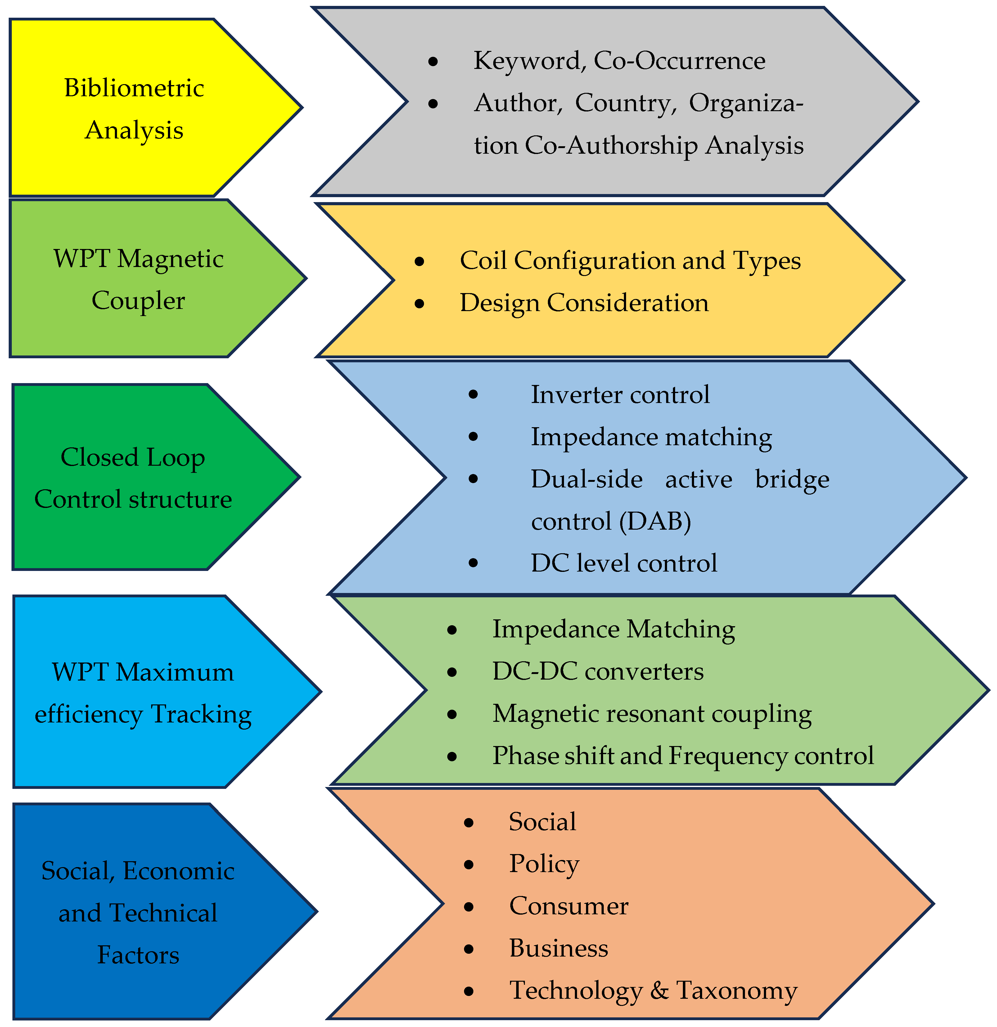
2. Methodology Bibliometric Data Extraction
- Document type was unrestricted to include all relevant re-sources.
- Research conducted between 2011 and 2024 was considered.
- Documents outside this period were excluded.
- Titles and abstracts were assessed to ensure relevance to the research topic.
- Only English-language publications were included, as it is the primary language of scientific discourse.
- Peer-reviewed publications were selected to ensure reliability and validity.
- Duplicate articles were removed to avoid redundancy.
2.1. Distribution of Bibliometric Documents and Scientometric Study
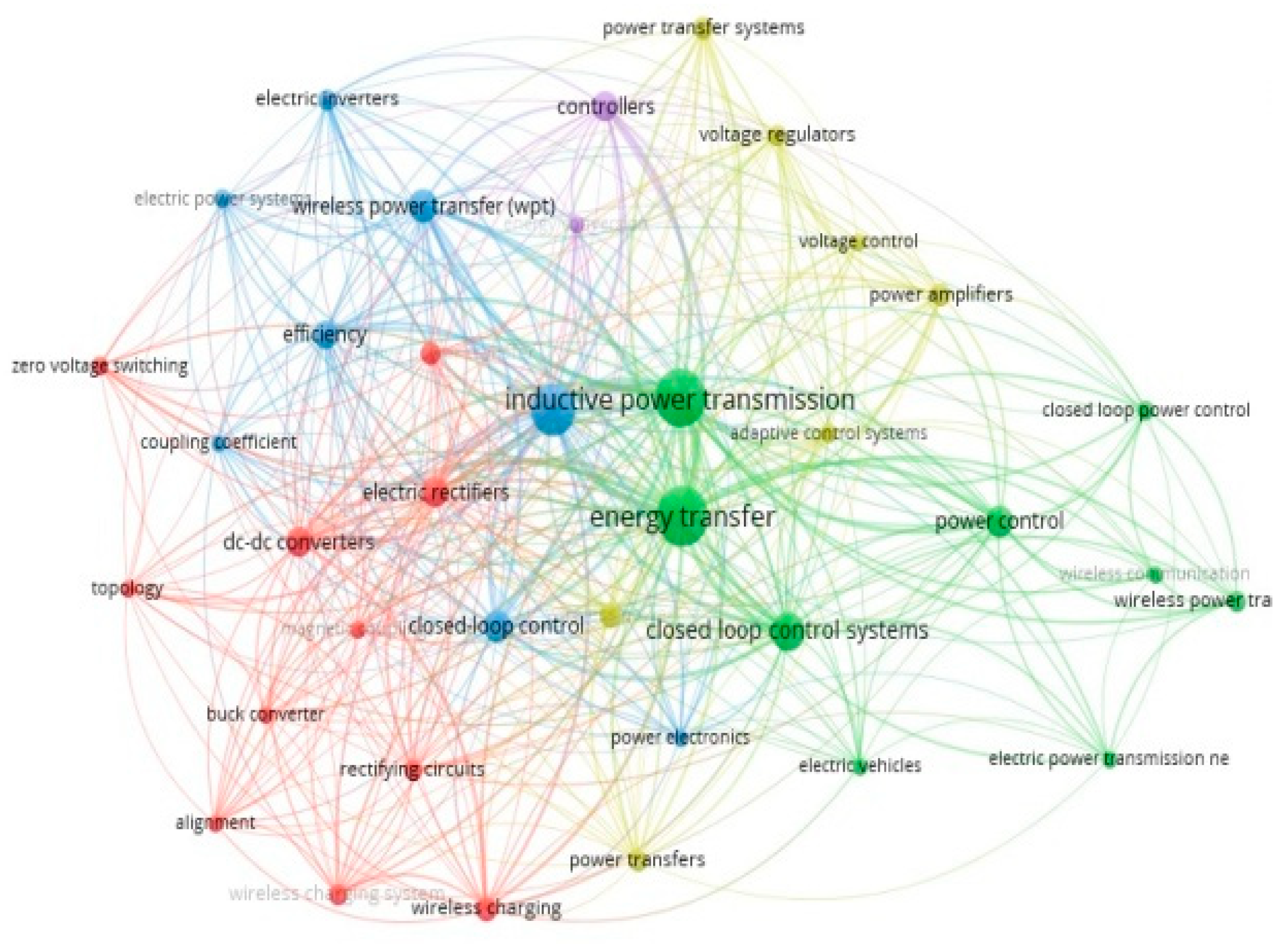
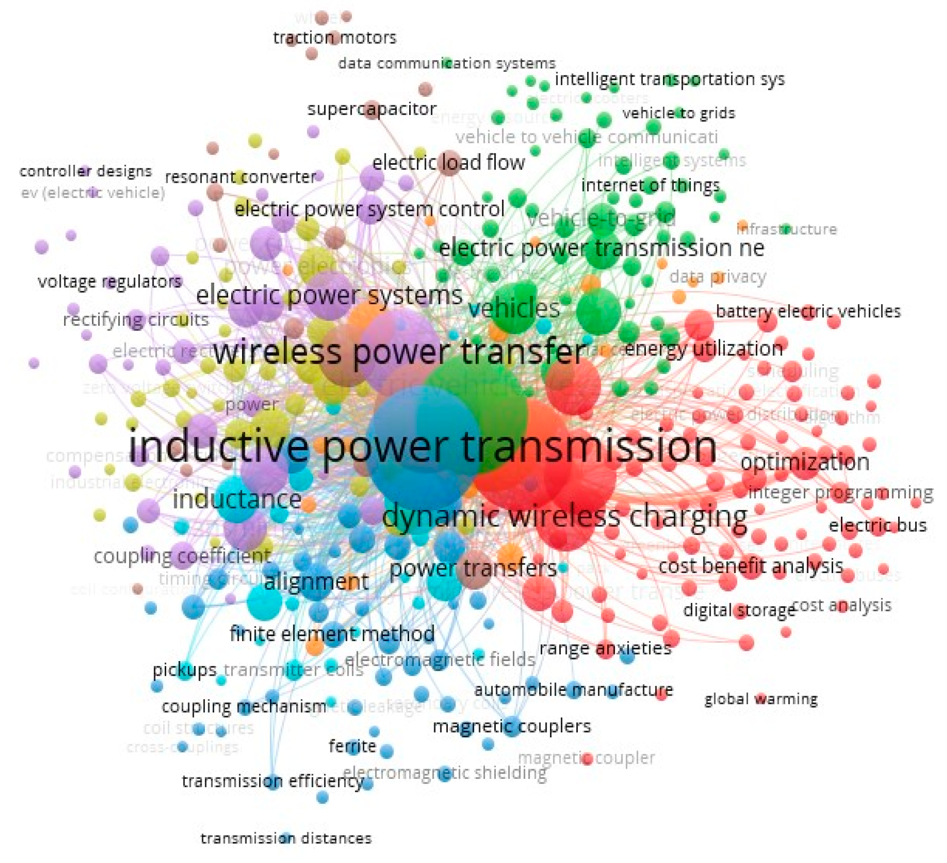
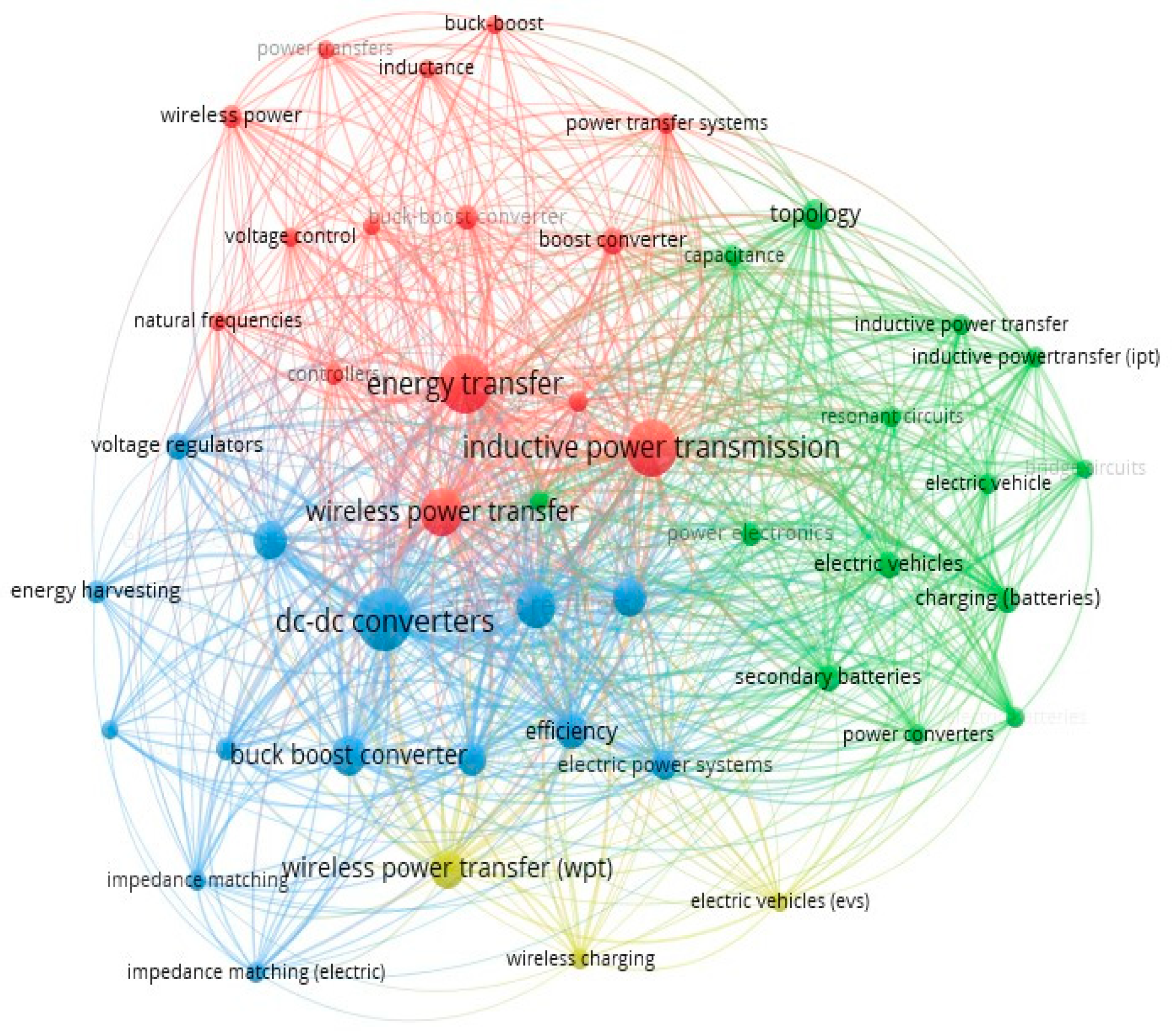
- The bibliometric analysis aimed to provide a comprehensive overview of the research landscape of wireless power transfer applied to EVs. Various metrics were used to analyze co-occurrence, co-authorship, co-citation, and citation patterns in the literature.
- In co-occurrence analysis, keywords, nations, and co-authors were used as measurement units. This analysis helped identify the most frequently occurring keywords, the most active nations in the field, and the most influential authors based on their co-authorship networks.
- Co-authorship analysis utilized authors, nations, and organizations as measurement units. This analysis identified collaborative networks among researchers, the most active countries in terms of collaboration, and the most influential organizations based on their co-authorship patterns.
- Co-citation analysis measured how often a particular author or source is cited by other authors or sources. This analysis helped identify the most influential authors and sources in the field.
- Citation analysis examined the citations of individual papers, authors, organizations, and sources. This analysis allowed for the identification of the most cited papers, authors, organizations, and sources, providing an overview of the most influential research in the field.
- The results of these analyses were visualized using network visualizations and density maps, offering a comprehensive overview of the intellectual landscape of the research field.
2.2. Keyword Co-Occurrence Study
2.3. Analysis of Author, Country, and Organization Co-Authorship
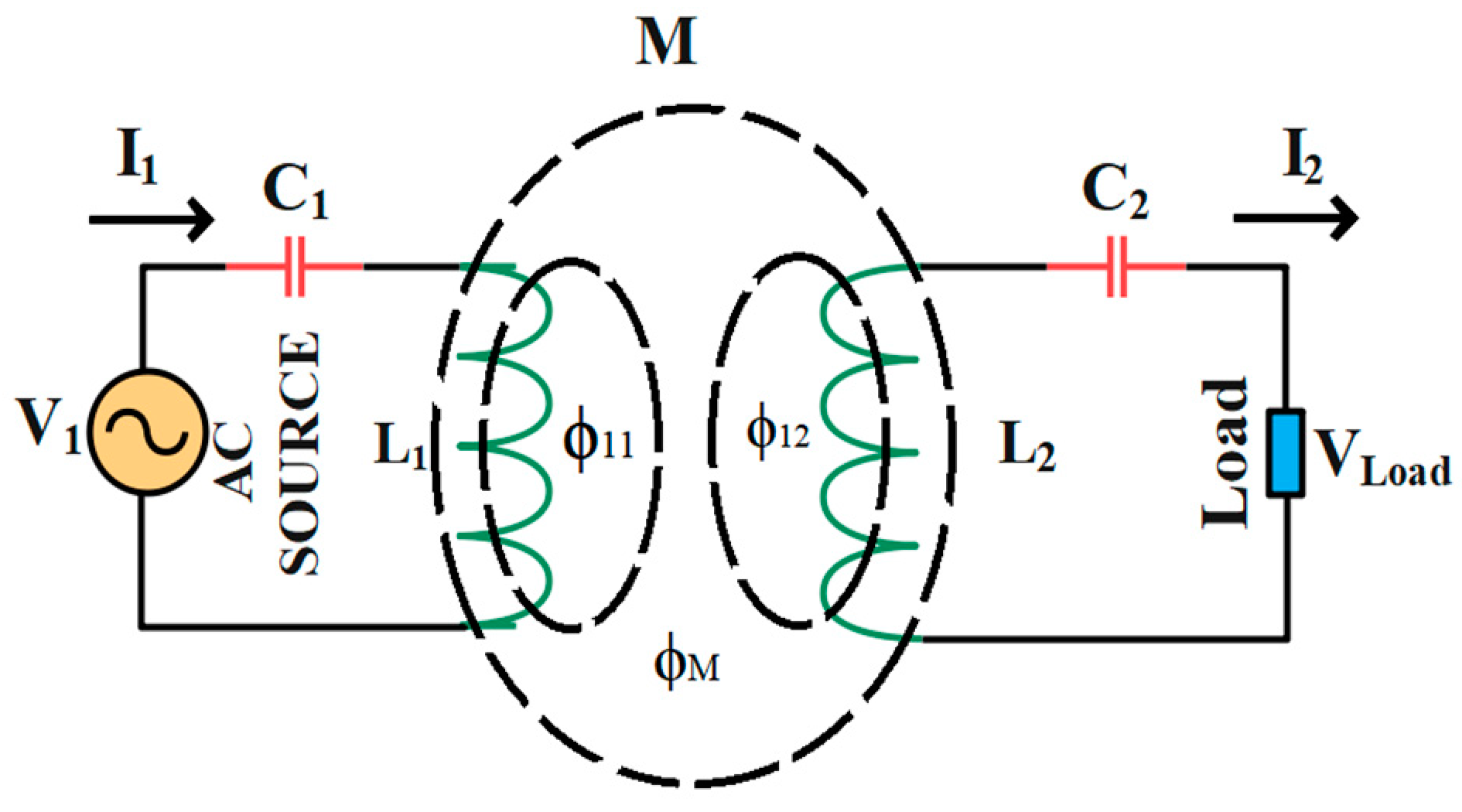
3. Design Consideration of WPT System
3.1. Coil Specification and Operating Principle
3.2. Coil Types
3.3. Finite Element Modeling
3.4. Design Objectives of Each Modules
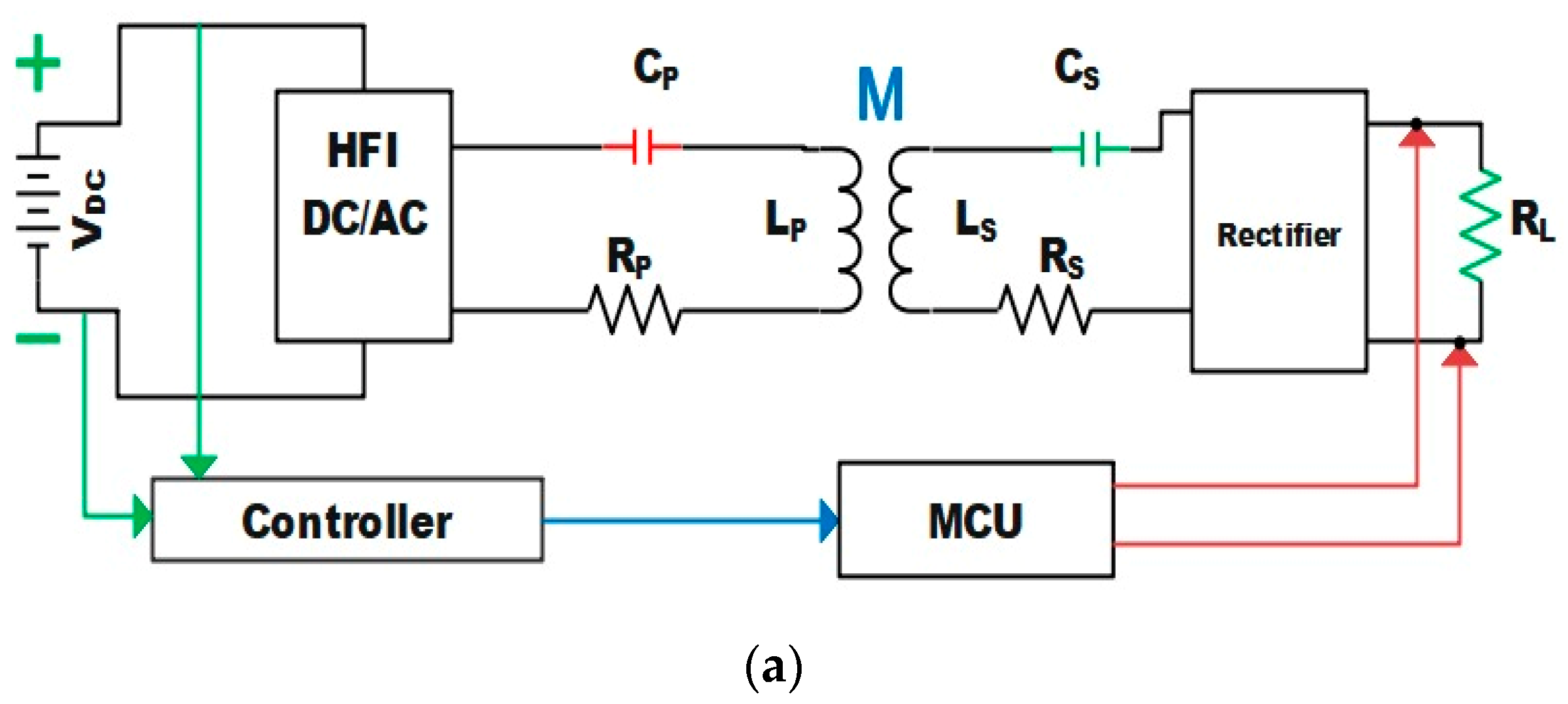
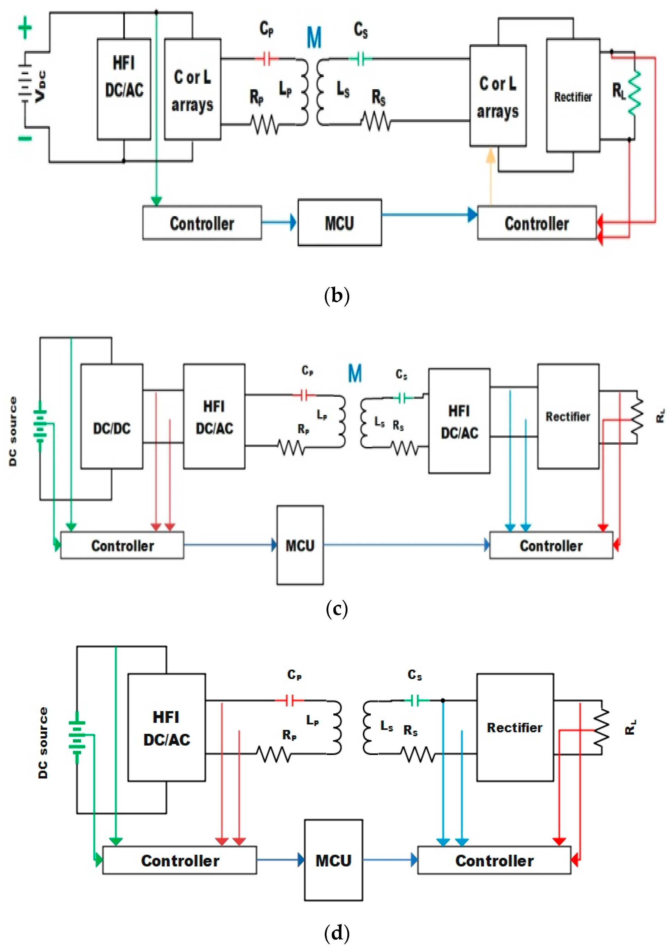
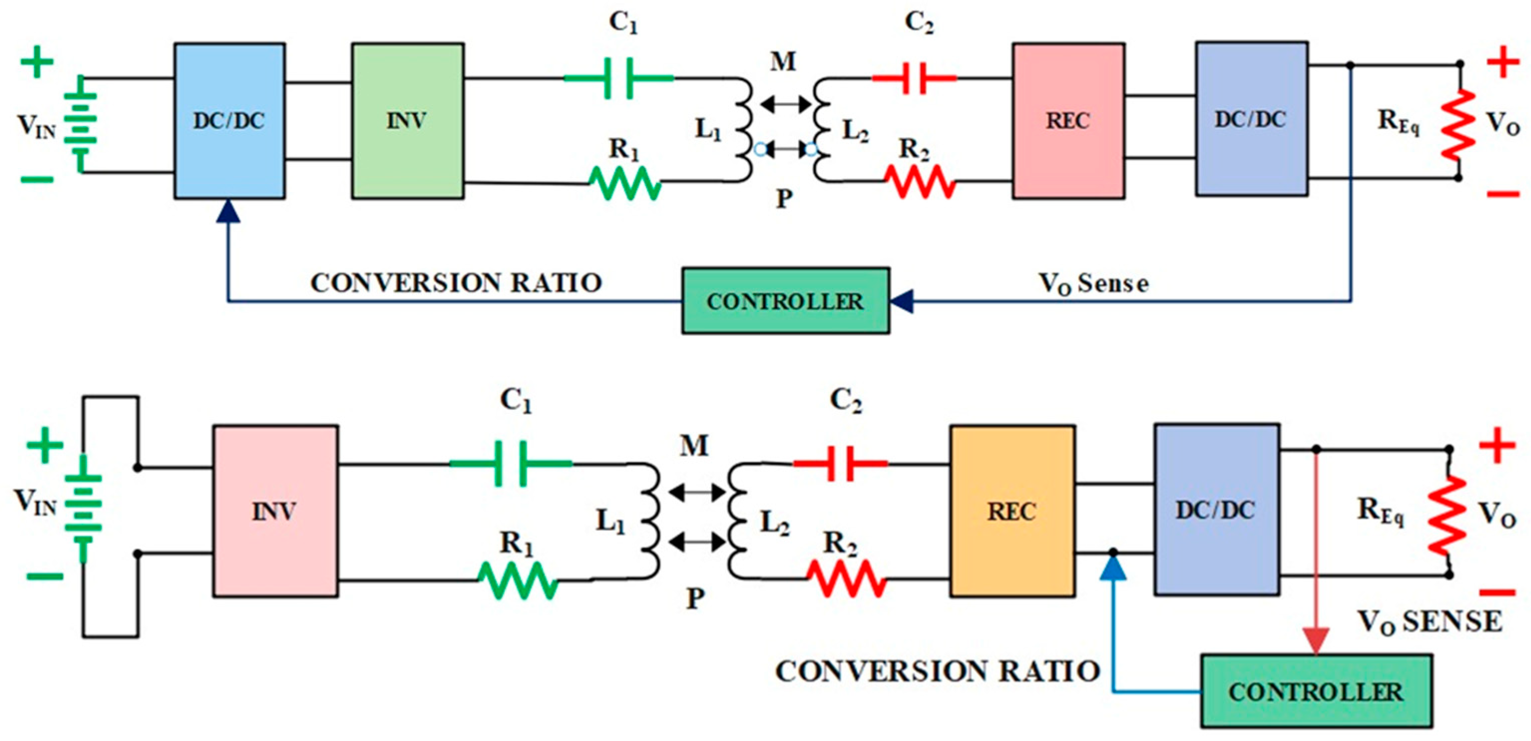
4. Closed-Loop Control Structure of WPT
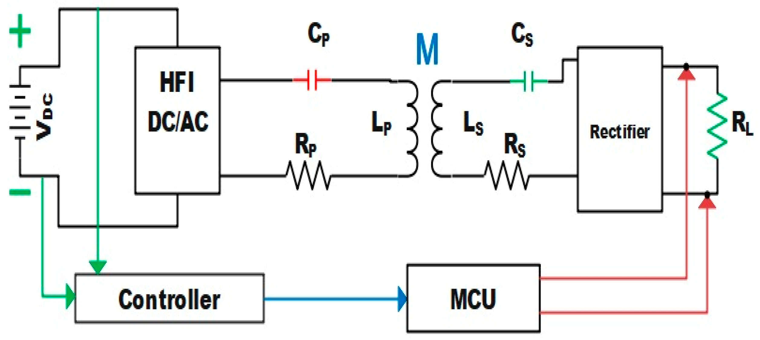
4.1. System Profile and Closed Loop System
4.2. Control Structure
- Inverter control;
- Impedance matching (IM);
- Dual-side active bridge control (DAB);
- DC level control.
4.3. Control Methods
4.4. Wireless Feedback Systems
4.5. Power and Data Frequency Division Multiplexing (FDM)
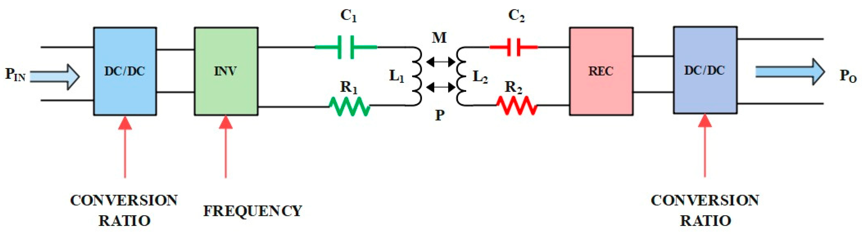
5. Maximum Efficiency Tracker in WPT System
5.1. Impedance Matching Using Passive Impedance Networks
5.2. Impedance Matching Using Active Rectifier
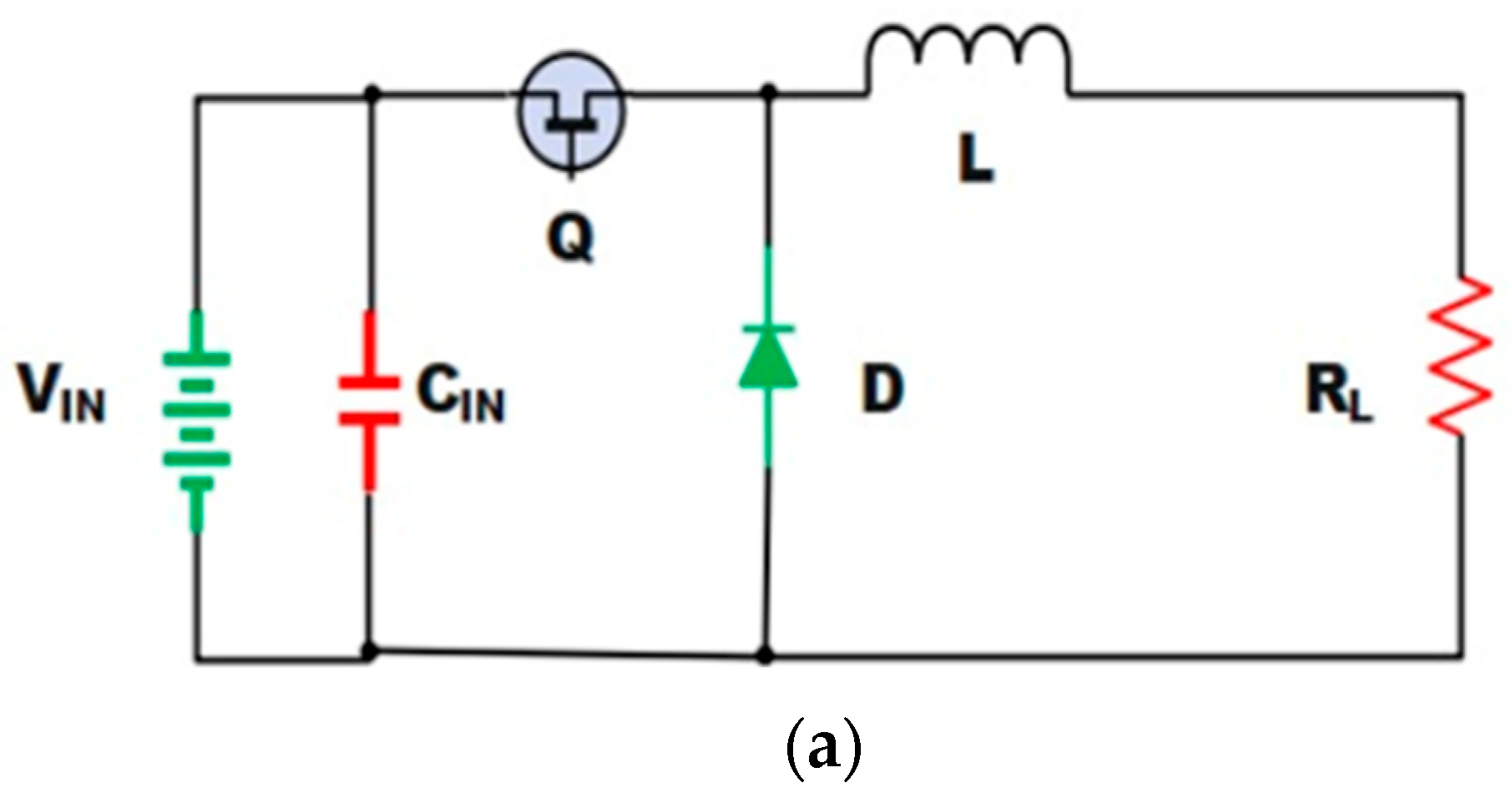
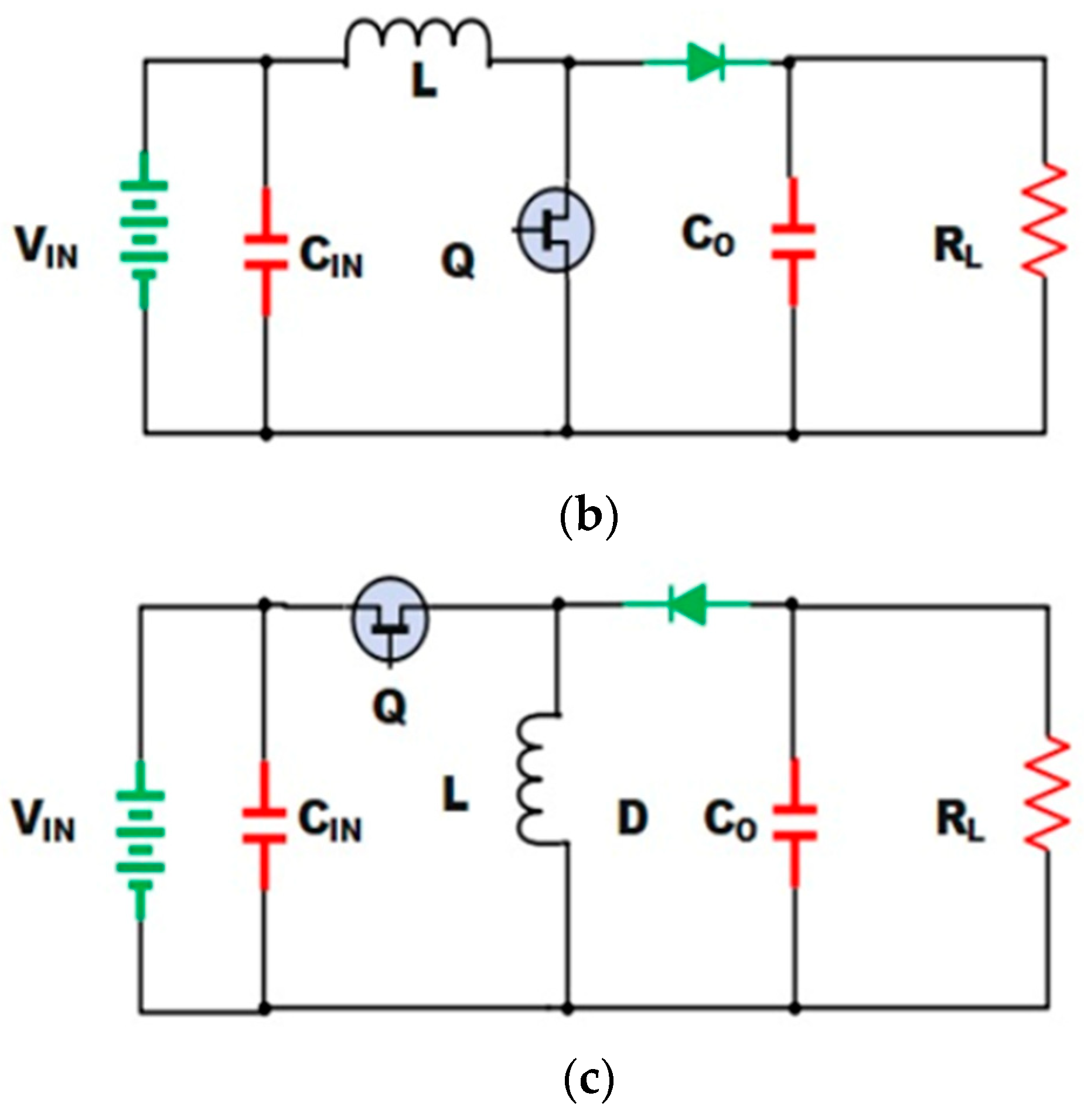
5.3. Impedance Matching Using DC–DC Converters
5.4. Maximum Efficiency Tracking Using DC–DC Converters
5.5. Maximum Efficiency Tracking Using Other Methods
5.5.1. MET Using Magnetic Resonant Coupling
5.5.2. Pre-Regulation Scheme
5.5.3. Post-Regulation Scheme
5.5.4. MET Using Phase Shift and Frequency Control
- A starting phase angle of 900 is applied, and the switching frequency is taken by finding the mean of the allowable range of frequency with the current frequency and applying it to the high-frequency inverter.
- The duty cycle is adjusted to regulate the charging current and voltage depending on the SoC of the battery.
- Calculating input power from the DC-link voltage and current.
- The phase shift is optimized with a starting number of 100% on time and the optimized switching frequency value after the switching frequency has been optimized.
- While buck converters maintain constant output power, phase shift is optimized to reduce input power.
- Finally, the optimized value of both phase shift and frequency are obtained, and the cycle is repeated after a timed delay.
6. Social, Economic and Technical Factors of DWPT
- The PEST structure, designed to explore the macro-environment, was adopted as part of the research effort [98]. PEST encompasses political, economic, societal, and technological forces within the system.
- Unstructured conversation, a qualitative, informal, guided methodology, aims to understand one’s experiences and perspectives within a modified social setting [99], striving to attain the same level of expertise and understanding as the respondent [88]. In-depth, partially structured discussions aim to uncover hidden motivations, biases, or attitudes toward sensitive topics.
- A swift review of available information was conducted as a time and resource-efficient strategy [87], yielding relevant data to support the analysis phase.
6.1. Stakeholder Selection
6.1.1. Transcribing
6.1.2. Analysis
6.1.3. Results
6.1.4. Policy
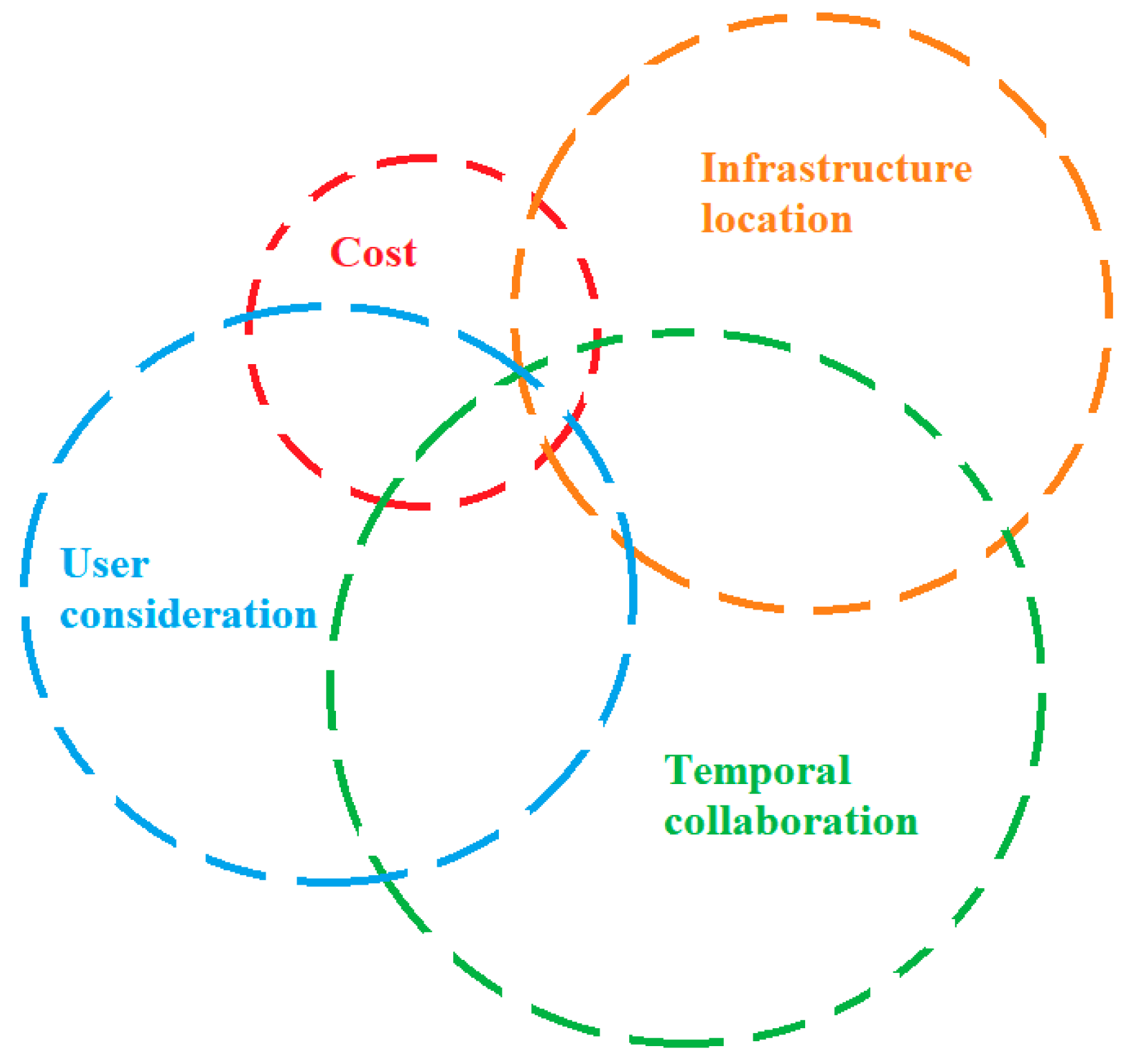
6.1.5. Cost
6.1.6. Infrastructure Location
6.1.7. Temporal Considerations
6.1.8. User Considerations
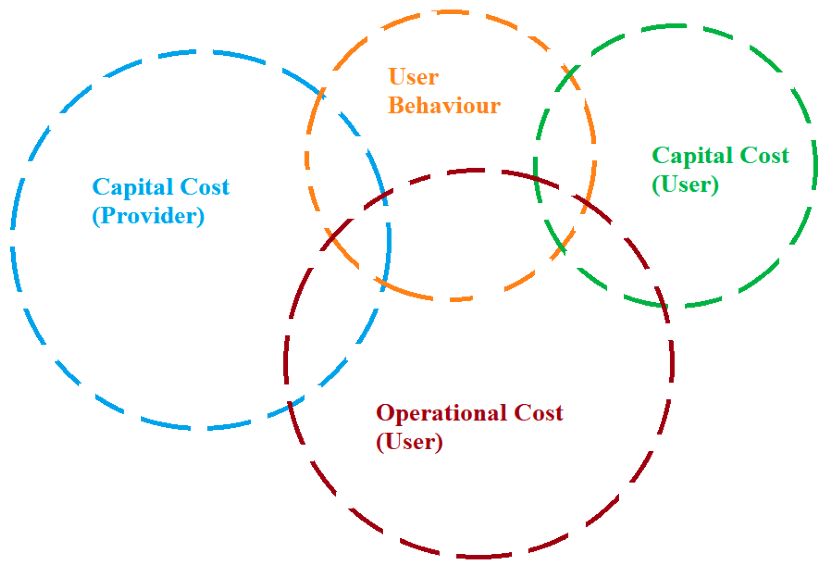
6.2. Consumer
6.2.1. Capital Cost (Provider)
6.2.2. User Behavior
6.2.3. Capital Cost (User)
6.2.4. Operational Cost User
6.3. Business
6.3.1. User Engagement
6.3.2. User Behavior
6.4. Technology
6.4.1. Stakeholder Communities
6.4.2. Product Standards
6.4.3. Performance Improvements
6.4.4. Performance Management
6.5. Discussion
6.5.1. Positioning
6.5.2. Battery Capacity
6.5.3. Daily Load Curve
6.5.4. Speed
6.5.5. Traffic
6.5.6. Infrastructure Air Gap
6.5.7. Road Gradient
6.5.8. Charging Infrastructure
7. Challenges and Limitations of DWPT
7.1. Wireless Magnetic Coupler
7.2. Infrastructure Development
7.3. Power Coil Interoperability
7.4. Grid and Renewable Integration
7.5. Resonance and Compensation
7.6. Safety and Health
7.7. Simultaneous Power and Communication
7.8. Shielding Material Challenges
7.9. Performance of WPT System
7.10. Maximum Power Transfer Efficiency
7.11. Miniaturization
7.12. Regulation and Limitation of WPT
7.13. Data Security
7.14. Future Paths for Research
- Creating more complex control algorithms that can adapt dynamically to changing circumstances and instantly maximize power transfer effectiveness. This involves utilizing artificial intelligence and machine learning together to anticipate and react to modifications in the charging environment.
- Research into cutting-edge techniques for keeping an eye on and optimizing the efficiency of power transfer. To continuously improve system performance, this may entail utilizing adaptive control methods and real-time data analytics.
- Investigation of innovative magnetic coupler arrangements that can improve the DWPT systems’ alignment tolerance and power transmission capacities. In order to lower losses and boost overall efficiency, this includes researching novel materials and geometric shapes.
- Research on novel designs and materials for compensating capacitors that can offer improved performance under dynamic loading circumstances is known as compensating capacitance innovation. This entails validating suggested solutions through experiments as well as theoretical modeling.
- To guarantee interoperability and ease of adoption, efforts are being made to integrate DWPT systems with the current EV infrastructure and standardize protocols. This entails working together with regulatory agencies and industry participants to create and execute thorough standards.
- Ongoing assessment of the socio-economic effects of DWPT technology, with an emphasis on policy frameworks, public acceptance, and cost–benefit analysis. The goal of this study should be to offer practical suggestions to industry executives and legislators to encourage the long-term growth of DWPT infrastructure.
- Lifecycle assessments and sustainability analysis are used to examine how DWPT systems affect the environment. The goal of this research is to find ways to reduce the environmental impact of DWPT technology and encourage its use as a more environmentally friendly charging method than traditional ones.
8. Conclusion
Author Contributions
Funding
Institutional Review Board Statement
Informed Consent Statement
Data Availability Statement
Conflicts of Interest
Abbreviations
| WPT | wireless power transfer | SWC | stationary wireless charging |
| EV | electric vehicle | DWC | dynamic wireless charging |
| P | proportional controller | DSRC | dedicated short-range communication |
| I | integral controller | FDM | frequency division multiplexing |
| D | derivative controller | kHz | kilo-hertz |
| PI | proportional–integral controllers | MHz | mega-hertz |
| PD | proportional–derivative controllers | MCU | microcontroller unit |
| PID | proportional–integral–derivative controllers | MET | maximum efficiency tracker |
| MPC | model predictive control | CCM | continuous conduction mode |
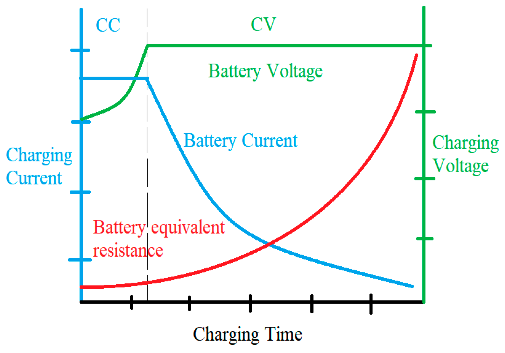
| CC | constant current | DCM | discontinuous conduction mode |
| CV | constant voltage | PWM | pulse width modulation |
| PV | photovoltaic | ESR | equivalent series resistance |
| IGBTs | insulated gate bipolar transistors | SOC | state of charge |
| MOSFET | metal-oxide-semiconductor field-effect transistor | PEST | political, economic, social, and technological factors |
| IM | impedance matching | DWPT | dynamic wireless power transfer |
| DAB | dual active bridge | DWCS | dynamic wireless charging solution |
| SPWM | sinusoidal pulse width modulation | EMC | electromagnetic compatibility |
| DDQ | double D quadrature pad | EVSE | electric vehicle supply equipment |
| ADC | analog-to-digital controller | MPTE | maximum power transfer efficiency |
| VSI | voltage source inverter | DSRC | dedicated short-range communication |
References
- Shin, S.; Shin, J.; Song, B.; Lee, S.; Kim, Y.; Jung, G.; Jeon, S. Wireless power transfer system for high power application and a method of segmentation. In Proceedings of the 2013 IEEE Wireless Power Transfer (WPT), Perugia, Italy, 15–16 May 2013; pp. 76–78. [Google Scholar] [CrossRef]
- Lee, C.H.; Jung, G.; Hosani, K.A.; Song, B.; Seo, D.-K.; Cho, D. Wireless Power Transfer System for an Autonomous Electric Vehicle. In Proceedings of the 2020 IEEE Wireless Power Transfer Conference (WPTC), Seoul, Republic of Korea, 15–19 November 2020; pp. 467–470. [Google Scholar] [CrossRef]
- Shin, J.; Shin, S.; Kim, Y.; Lee, S.; Song, B.; Jung, G. Optimal current control of a wireless power transfer system for high power efficiency. In Proceedings of the 2012 Electrical Systems for Aircraft, Railway and Ship Propulsion, Bologna, Italy, 16–18 October 2012; pp. 1–4. [Google Scholar] [CrossRef]
- Yu, T.-C.; Yang, C.-L. Design and analysis of dual-frequency power amplifier for wireless power and data transfer application. In Proceedings of the 2017 IEEE Wireless Power Transfer Conference (WPTC), Taipei, Taiwan, 10–12 May 2017; pp. 1–4. [Google Scholar] [CrossRef]
- Tang, W.; Cheng, Z. A Real-Time Tracking Algorithm for 3D Wireless Maximum Power Transfer to a Moving Device. In Proceedings of the 2020 IEEE PELS Workshop on Emerging Technologies: Wireless Power Transfer (WoW), Seoul, Republic of Korea, 15–19 November 2020; pp. 27–34. [Google Scholar] [CrossRef]
- Minnaert, B.; Stevens, N. Maximizing the Power Transfer for a Mixed Inductive and Capacitive Wireless Power Transfer System. In Proceedings of the 2018 IEEE Wireless Power Transfer Conference (WPTC), Montreal, QC, Canada, 3–7 June 2018; pp. 1–4. [Google Scholar] [CrossRef]
- Abdolkhani, A. Single-switch soft-switched power flow controller for wireless power transfer applications. In Proceedings of the 2017 IEEE Wireless Power Transfer Conference (WPTC), Taipei, Taiwan, 10–12 May 2017; pp. 1–4. [Google Scholar] [CrossRef]
- Luo, S.; Li, S.; Zhao, H. Reactive power comparison of four-coil, LCC and CLC compensation network for wireless power transfer. In Proceedings of the 2017 IEEE PELS Workshop on Emerging Technologies: Wireless Power Transfer (WoW), Chongqing, China, 20–22 May 2017; pp. 268–271. [Google Scholar] [CrossRef]
- Lee, S.; Jung, G.; Shin, S.; Kim, Y.; Song, B.; Shin, J.; Cho, D. The optimal design of high-powered power supply modules for wireless power transferred train. In Proceedings of the 2012 Electrical Systems for Aircraft, Railway and Ship Propulsion, Bologna, Italy, 16–18 October 2012; pp. 1–4. [Google Scholar] [CrossRef]
- Zhang, J.; Liu, Y.; Dong, S.; Zhu, C.; Wang, S.; Wu, X.; Wei, B. Wireless Power Transfer Based on the Structure of Plane-Shaped Cores. In Proceedings of the 2018 IEEE PELS Workshop on Emerging Technologies: Wireless Power Transfer (Wow), Montreal, QC, Canada, 3–7 June 2018; pp. 1–5. [Google Scholar] [CrossRef]
- Wang, Y.; Geng, Y.; Yang, Z.; Lin, F. Parameter Optimization of Modern Tram Wireless Power Transfer Power Supply System. In Proceedings of the 2019 IEEE PELS Workshop on Emerging Technologies: Wireless Power Transfer (WoW), London, UK, 18–21 June 2019; pp. 49–52. [Google Scholar] [CrossRef]
- Luo, B.; Long, T.; Guo, L.; Mai, R.; He, Z. Analysis and Design of Hybrid Inductive and Capacitive Wireless Power Transfer System. In Proceedings of the 2019 IEEE Applied Power Electronics Conference and Exposition (APEC), Anaheim, CA, USA, 17–21 March 2019; pp. 3107–3110. [Google Scholar] [CrossRef]
- Hwang, K.; Chung, S.; Yoon, U.; Lee, M.; Ahn, S. Thermal analysis for temperature robust wireless power transfer systems. In Proceedings of the 2013 IEEE Wireless Power Transfer (WPT), Perugia, Italy, 15–16 May 2013; pp. 52–55. [Google Scholar] [CrossRef]
- Chai, R.; Mortazawi, A. A New Coupling Insensitive Nonlinear Capacitive Resonant Wireless Power Transfer Circuit. In Proceedings of the 2021 IEEE Wireless Power Transfer Conference (WPTC), San Diego, CA, USA, 1–4 June 2021; pp. 1–4. [Google Scholar] [CrossRef]
- Kishan, D.; Nayak, P.S.R. Wireless power transfer technologies for electric vehicle battery charging—A state of the art. In Proceedings of the 2016 International Conference on Signal Processing, Communication, Power and Embedded System (SCOPES), Paralakhemundi, India, 3–5 October 2016; pp. 2069–2073. [Google Scholar] [CrossRef]
- Debbou, M.; Colet, F. Inductive wireless power transfer for electric vehicle dynamic charging. In Proceedings of the 2016 IEEE PELS Workshop on Emerging Technologies: Wireless Power Transfer (WoW), Knoxville, TN, USA, 4–6 October 2016; pp. 118–122. [Google Scholar] [CrossRef]
- Hans, M.; Deshmukh, P. Bidirectional Wireless Power Transfer System for Electric Vehicles—Overview and Implementation. In Proceedings of the 2020 International Conference on Smart Electronics and Communication (ICOSEC), Trichy, India, 10–12 September 2020; pp. 1062–1065. [Google Scholar] [CrossRef]
- Jaisiva, S.; Ashika, S.; Snega, M.; Baranidevi, R. A Novel Integration of Wireless Power Transfer Topology for Electric Vehicle Application using Tesla Coil. In Proceedings of the 2023 2nd International Conference on Smart Technologies and Systems for Next Generation Computing (ICSTSN), Villupuram, India, 21–22 April 2023; pp. 1–5. [Google Scholar] [CrossRef]
- Venkatesan, M.; Narayanamoorthi, R.; AboRas, K.M.; Emara, A. Efficient Bidirectional Wireless Power Transfer System Control Using Dual Phase Shift PWM Technique for Electric Vehicle Applications. IEEE Access 2024, 12, 27739–27755. [Google Scholar] [CrossRef]
- Chu, S.Y.; Cui, X.; Zan, X.; Avestruz, A.-T. Transfer-Power Measurement Using a Non-Contact Method for Fair and Accurate Metering of Wireless Power Transfer in Electric Vehicles. IEEE Trans. Power Electron. 2022, 37, 1244–1271. [Google Scholar] [CrossRef]
- Chung, Y.D.; Lee, C.Y.; Kang, H.; Park, Y.G. Design Considerations of Superconducting Wireless Power Transfer for Electric Vehicle at Different Inserted Resonators. IEEE Trans. Appl. Supercond. 2016, 26, 0603605. [Google Scholar] [CrossRef]
- Yan, Z.; Song, B.; Zhang, Y.; Zhang, K.; Mao, Z.; Hu, Y. A Rotation-Free Wireless Power Transfer System with Stable Output Power and Efficiency for Autonomous Underwater Vehicles. IEEE Trans. Power Electron. 2019, 34, 4005–4008. [Google Scholar] [CrossRef]
- Bertoluzzo, M.; Kumar, A.; Sagar, A. Control Strategy for a Bidirectional Wireless Power Transfer System with Vehicle to Home Functionality. IEEE Access 2023, 11, 60421–60448. [Google Scholar] [CrossRef]
- Deng, J.; Li, W.; Nguyen, T.D.; Li, S.; Mi, C.C. Compact and Efficient Bipolar Coupler for Wireless Power Chargers: Design and Analysis. IEEE Trans. Power Electron. 2015, 30, 6130–6140. [Google Scholar] [CrossRef]
- Chung, Y.D.; Lee, C.Y.; Kang, H.K.; Park, Y.G. Design Consideration and Efficiency Comparison of Wireless Power Transfer with HTS and Cooled Copper Antennas for Electric Vehicle. IEEE Trans. Appl. Supercond. 2015, 25, 5000205. [Google Scholar] [CrossRef]
- Fathollahi, A.; Derakhshandeh, S.Y.; Ghiasian, A.; Masoum, M.A.S. Optimal Siting and Sizing of Wireless EV Charging Infrastructures Considering Traffic Network and Power Distribution System. IEEE Access 2022, 10, 117105–117117. [Google Scholar] [CrossRef]
- Miller, J.M.; Onar, O.C.; Chinthavali, M. Primary-Side Power Flow Control of Wireless Power Transfer for Electric Vehicle Charging. IEEE J. Emerg. Sel. Top. Power Electron. 2015, 3, 147–162. [Google Scholar] [CrossRef]
- Machura, P.; De Santis, V.; Li, Q. Driving Range of Electric Vehicles Charged by Wireless Power Transfer. IEEE Trans. Veh. Technol. 2020, 69, 5968–5982. [Google Scholar] [CrossRef]
- Choi, S.Y.; Gu, B.W.; Jeong, S.Y.; Rim, C.T. Advances in Wireless Power Transfer Systems for Roadway-Powered Electric Vehicles. IEEE J. Emerg. Sel. Top. Power Electron. 2015, 3, 18–36. [Google Scholar] [CrossRef]
- Wang, L.; Madawala, U.K.; Wong, M.-C. A Wireless Vehicle-to-Grid-to-Home Power Interface with an Adaptive DC Link. IEEE J. Emerg. Sel. Top. Power Electron. 2021, 9, 2373–2383. [Google Scholar] [CrossRef]
- Sagar, A.; Kashyap, A.; Nasab, M.A.; Padmanaban, S.; Bertoluzzo, M.; Kumar, A.; Blaabjerg, F. A Comprehensive Review of the Recent Development of Wireless Power Transfer Technologies for Electric Vehicle Charging Systems. IEEE Access 2023, 11, 83703–83751. [Google Scholar] [CrossRef]
- Moon, S.; Moon, G.-W. Wireless Power Transfer System with an Asymmetric Four-Coil Resonator for Electric Vehicle Battery Chargers. IEEE Trans. Power Electron. 2016, 31, 6844–6854. [Google Scholar] [CrossRef]
- Deng, Z.; Hu, H.; Su, Y.; Chen, F.; Xiao, J.; Tang, C.; Lin, T. Design of a 60-kW EV Dynamic Wireless Power Transfer System with Dual Transmitters and Dual Receivers. IEEE J. Emerg. Sel. Top. Power Electron. 2024, 12, 316–327. [Google Scholar] [CrossRef]
- Sinha, S.; Kumar, A.; Regensburger, B.; Afridi, K.K. A New Design Approach to Mitigating the Effect of Parasitics in Capacitive Wireless Power Transfer Systems for Electric Vehicle Charging. IEEE Trans. Transp. Electrif. 2019, 5, 1040–1059. [Google Scholar] [CrossRef]
- Li, S.; Mi, C.C. Wireless Power Transfer for Electric Vehicle Applications. IEEE J. Emerg. Sel. Top. Power Electron. 2015, 3, 4–17. [Google Scholar] [CrossRef]
- Ramakrishnan, V.; Savio, D.; Balaji, C.; Rajamanickam, N.; Kotb, H.; Elrashidi, A.; Nureldeen, W. A Comprehensive Review on Efficiency Enhancement of Wireless Charging System for the Electric Vehicles Applications. IEEE Access 2024, 12, 46967–46994. [Google Scholar] [CrossRef]
- Zhang, Y.; Pan, W.; Wang, H.; Shen, Z.; Wu, Y.; Dong, J.; Mao, X. Misalignment-Tolerant Dual-Transmitter Electric Vehicle Wireless Charging System with Reconfigurable Topologies. IEEE Trans. Power Electron. 2022, 37, 8816–8819. [Google Scholar] [CrossRef]
- Li, X.; Zheng, F.; Wang, H.; Sun, Y.; Dai, X.; Hu, J. A Simultaneous Power and Data Transfer Method for Dynamic Wireless Charging Electric Vehicles. IEEE J. Emerg. Sel. Top. Power Electron. 2024, 12, 328–340. [Google Scholar] [CrossRef]
- Huang, Y.; Liu, C.; Zhou, Y.; Xiao, Y.; Liu, S. Power Allocation for Dynamic Dual-Pickup Wireless Charging System of Electric Vehicle. IEEE Trans. Magn. 2019, 55, 8600106. [Google Scholar] [CrossRef]
- Jeong, S.; Jang, Y.J.; Kum, D. Economic Analysis of the Dynamic Charging Electric Vehicle. IEEE Trans. Power Electron. 2015, 30, 6368–6377. [Google Scholar] [CrossRef]
- Wu, J.; Li, Y.; Dai, X.; Gao, R.; He, M. A Dynamic Power Transfer Route Construction and Optimization Method Considering Random Node Distribution for Wireless Power Transfer Network. IEEE Trans. Power Electron. 2024, 39, 4858–4869. [Google Scholar] [CrossRef]
- Chung, Y.D.; Park, E.Y.; Lee, W.S.; Lee, J.Y. Impact Investigations and Characteristics by Strong Electromagnetic Field of Wireless Power Charging System for Electric Vehicle Under Air and Water Exposure Indexes. IEEE Trans. Appl. Supercond. 2018, 28, 3600905. [Google Scholar] [CrossRef]
- Regensburger, B.; Sinha, S.; Kumar, A.; Maji, S.; Afridi, K.K. High-Performance Multi-MHz Capacitive Wireless Power Transfer System for EV Charging Utilizing Interleaved-Foil Coupled Inductors. IEEE J. Emerg. Sel. Top. Power Electron. 2022, 10, 35–51. [Google Scholar] [CrossRef]
- Machnoor, M.; Lazzi, G. Wireless Power Transfer: Types of Reflected Impedances and Maximum Power Transfer Theorem. IEEE Antennas Wirel. Propag. Lett. 2020, 19, 1709–1713. [Google Scholar] [CrossRef]
- Newbolt, T.; Mandal, P.; Wang, H.; Zane, R. Sustainability of Dynamic Wireless Power Transfer Roadway for In-Motion Electric Vehicle Charging. IEEE Trans. Transp. Electrif. 2024, 10, 1347–1362. [Google Scholar] [CrossRef]
- Jang, Y.J.; Suh, E.S.; Kim, J.W. System Architecture and Mathematical Models of Electric Transit Bus System Utilizing Wireless Power Transfer Technology. IEEE Syst. J. 2016, 10, 495–506. [Google Scholar] [CrossRef]
- Casaucao, I.; Triviño, A.; Corti, F.; Reatti, A. SS and LCC–LCC in Simultaneous Wireless Power and Data Transfer: A Comparative Analysis for SAE J2954-Compliant EVs. IEEE Trans. Ind. Inform. 2024, 20, 8195–8206. [Google Scholar] [CrossRef]
- Elmeligy, A.O.; Elghanam, E.; Hassan, M.S.; Osman, A.H.; Shalaby, A.A.; Shaaban, M. Optimal Planning of Dynamic Wireless Charging Infrastructure for Electric Vehicles. IEEE Access 2024, 12, 30661–30673. [Google Scholar] [CrossRef]
- Zheng, Z.; Fang, X.; Zheng, Y.; Feng, H. A Wireless Power Transfer System Based on Dual-Band Metamaterials. IEEE Microw. Wirel. Compon. Lett. 2022, 32, 615–618. [Google Scholar] [CrossRef]
- Zhu, Q.; Zhang, Y.; Liao, C.; Guo, Y.; Wang, L.; Li, F. Experimental Study on Asymmetric Wireless Power Transfer System for Electric Vehicle Considering Ferrous Chassis. IEEE Trans. Transp. Electrif. 2017, 3, 427–433. [Google Scholar] [CrossRef]
- Samanta, S.; Rathore, A.K. A New Current-Fed CLC Transmitter and LC Receiver Topology for Inductive Wireless Power Transfer Application: Analysis, Design, and Experimental Results. IEEE Trans. Transp. Electrif. 2015, 1, 357–368. [Google Scholar] [CrossRef]
- Zhang, W.; White, J.C.; Abraham, A.M.; Mi, C.C. Loosely Coupled Transformer Structure and Interoperability Study for EV Wireless Charging Systems. IEEE Trans. Power Electron. 2015, 30, 6356–6367. [Google Scholar] [CrossRef]
- Alghawi, M.; Mounsef, J. Overview of Vehicle-to-Vehicle Energy Sharing Infrastructure. IEEE Access 2024, 12, 54567–54589. [Google Scholar] [CrossRef]
- Quirós, J.C.; Guerrero, E.V.; Sangeno, J.K.; Triviño, A. Magnetic Integration of Circular Pads and LCC-LCC for EV Wireless Charging Tolerant to Misalignment. IEEE Access 2023, 11, 98558–98565. [Google Scholar] [CrossRef]
- Wu, L.; Zhang, B.; Zhou, J. Efficiency Improvement of the Parity-Time-Symmetric Wireless Power Transfer System for Electric Vehicle Charging. IEEE Trans. Power Electron. 2020, 35, 12497–12508. [Google Scholar] [CrossRef]
- Onar, O.C.; Chinthavali, M.; Campbell, S.L.; Seiber, L.E.; White, C.P. Vehicular Integration of Wireless Power Transfer Systems and Hardware Interoperability Case Studies. IEEE Trans. Ind. 2019, 55, 5223–5234. [Google Scholar] [CrossRef]
- Zakerian, A.; Vaez-Zadeh, S.; Babaki, A. A Dynamic WPT System with High Efficiency and High Power Factor for Electric Vehicles. IEEE Trans. Power Electron. 2020, 35, 6732–6740. [Google Scholar] [CrossRef]
- Hsieh, Y.-C.; Lin, Z.-R.; Chen, M.-C.; Hsieh, H.-C.; Liu, Y.-C.; Chiu, H.-J. High-Efficiency Wireless Power Transfer System for Electric Vehicle Applications. IEEE Trans. Circuits Syst. II Express Briefs 2017, 64, 942–946. [Google Scholar] [CrossRef]
- Li, W.; Zhao, H.; Li, S.; Deng, J.; Kan, T.; Mi, C.C. Integrated LCC Compensation Topology for Wireless Charger in Electric and Plug-in Electric Vehicles. IEEE Trans. Ind. Electron. 2015, 62, 4215–4225. [Google Scholar] [CrossRef]
- Lee, T.-S.; Huang, S.-J.; Wu, M.-J. Enhancement of Wireless Power Transfer for Automated Guided Vehicles Considering Disturbance Suppression. IEEE Access 2023, 11, 21508–21518. [Google Scholar] [CrossRef]
- Park, C.; Lee, S.; Jeong, S.Y.; Cho, G.-H.; Rim, C.T. Uniform Power I-Type Inductive Power Transfer System with DQ-Power Supply Rails for On-Line Electric Vehicles. IEEE Trans. Power Electron. 2015, 30, 6446–6455. [Google Scholar] [CrossRef]
- Liang, M.; Drissi, K.E.K.; Pasquier, C. Frequency Domain Analysis of a Dynamic Wireless Transfer System for Electric Vehicles. IEEE Access 2024, 12, 72777–72793. [Google Scholar] [CrossRef]
- Yu, X.; Zhang, J.; Liu, M.; Yang, X.; Huang, Y.; Yen, T.-J.; Zhou, J. Dual-Module Ultrawide Dynamic-Range High-Power Rectifier for WPT Systems. Energies 2024, 17, 2707. [Google Scholar] [CrossRef]
- Zhang, R.; Li, X.; Sun, C.; Yang, S.; Tian, Y.; Tian, J. State of Charge and Temperature Joint Estimation Based on Ultrasonic Reflection Waves for Lithium-Ion Battery Applications. Batteries 2023, 9, 335. [Google Scholar] [CrossRef]
- Hou, S.; Zhang, B.; Hou, Y.; Sun, X.; Zhang, T.; Zhang, X.; Sun, Q. Analysis of Leakage Current in Dynamic Wireless Power Transfer Systems Based on LCC-S Architecture. World Electr. Veh. J. 2024, 15, 225. [Google Scholar] [CrossRef]
- Shevchenko, V.; Pakhaliuk, B.; Husev, O.; Vinnikov, D.; Strzelecki, R. Wireless Charging Station Design for Electric Scooters: Case Study Analysis. Energies 2024, 17, 2472. [Google Scholar] [CrossRef]
- Song, T.; Huang, W.; Rao, T.; Chang, Y.; Yan, H. Self-Switching Wireless Power Transfer System Design with Constant Current/Constant Voltage Output Features Based on LCC-LCL/S Topology. Electronics 2024, 13, 1729. [Google Scholar] [CrossRef]
- Shin, Y.; Woo, S. Reactive Shield for Reducing the Magnetic Field of a Wireless Power Transfer System with Dipole Coil Structure. Electronics 2024, 13, 1712. [Google Scholar] [CrossRef]
- Cai, J.; Sun, P.; Ji, K.; Wu, X.; Ji, H.; Wang, Y.; Rong, E. Constant-Voltage and Constant-Current Controls of the Inductive Power Transfer System for Electric Vehicles Based on Full-Bridge Synchronous Rectification. Electronics 2024, 13, 1686. [Google Scholar] [CrossRef]
- Wang, K.; Jiang, H.; Peng, J.; Li, H. ClosedLoop Control of Pulse-Density-Modulated Wireless Power Transfer with Fast MEPT. Electronics 2024, 13, 1619. [Google Scholar] [CrossRef]
- Cortes, D.; Hernandez-Gonzalez, L.; Ramirez-Hernandez, J.; Vargas, M. Modeling and Control of an Inductive Power Transmitter Based on Buck–Half Bridge–Resonant Tank. Electronics 2024, 13, 1593. [Google Scholar] [CrossRef]
- Hu, Y.; Dong, W.; Li, X.; Zhang, H.; Men, L. Active Regulation of Electromagnetic Force in Wireless Power Transfer Systems. Electronics 2024, 13, 1568. [Google Scholar] [CrossRef]
- Jiang, J.; Meng, Z. Frequency Stability Analysis and Charging Area Expanding Optimal Design for Matrix Coupling Mechanism in Wireless Power Transfer System. Electronics 2024, 13, 1312. [Google Scholar] [CrossRef]
- Okada, M.; Miwa, K.; Kodera, S.; Hirata, A. Compliance Assessment of the Spatial Averaging Method for Magnetic Field Leakage from a Wireless Power Transfer System in Electric Vehicles. Appl. Sci. 2024, 14, 2672. [Google Scholar] [CrossRef]
- Wang, J.; Hou, Y.; Shi, Z.; Sun, Q.; Guo, Y.; Cai, S.; Liu, Z. Design and Analysis of an H-Type Pickup for Multi-Segment Wireless Power Transfer Systems. Electronics 2024, 13, 1125. [Google Scholar] [CrossRef]
- Rabih, M.; Takruri, M.; Al-Hattab, M.; Alnuaimi; Bin Thaleth, M.R. Wireless Charging for Electric Vehicles: A Survey and Comprehensive Guide. World Electr. Veh. J. 2024, 15, 118. [Google Scholar] [CrossRef]
- Iqbal, S.; Alshammari, N.F.; Shouran, M.; Massoud, J. Smart and Sustainable Wireless Electric Vehicle Charging Strategy with Renewable Energy and Internet of Things Integration. Sustainability 2024, 16, 2487. [Google Scholar] [CrossRef]
- Sari, V. Design and Implementation of a Wireless Power Transfer System for Electric Vehicles. World Electr. Veh. J. 2024, 15, 110. [Google Scholar] [CrossRef]
- Wang, P.; Li, Q.; Liu, Y.; Yuan, W.; Yan, K.; Pang, Z. A Novel Impedance Matching of Class DE Inverter for High Efficiency, Wide Impedance WPT System. Electronics 2024, 13, 959. [Google Scholar] [CrossRef]
- Lukočius, R.; Nakutis, Ž.; Vilkauskas, A.; Deltuva, R.; Romikaitis, L. Analysis of Coil Systems with Non-Symmetrical Fe Backings for Electrical Vehicle Wireless Charging Applications. Appl. Sci. 2024, 14, 1380. [Google Scholar] [CrossRef]
- Zhang, B.; Cao, Y.; Hou, Y.; Hou, S.; Guo, Y.; Tian, J.; He, X. Analysis and Design Considerations for Transmitter-Compensated Inductance Mistuning in a WPT System with LCC-S Topology. World Electr. Veh. J. 2024, 15, 45. [Google Scholar] [CrossRef]
- Herceg, D.; Rajs, V.; Despotović, Ž.; Popadić, B.; Šiljegović, M.; Kiraly, Z.; Vizvari, Z.; Wizner, K.; Felde, I.; Odry, P.; et al. Double-Layer Coils Design for 11 kW Wireless Power Transfer. Electronics 2024, 13, 547. [Google Scholar] [CrossRef]
- Song, K.; Lan, Y.; Zhang, X.; Jiang, J.; Sun, C.; Yang, G.; Yang, F.; Lan, H. A Review on Interoperability of Wireless Charging Systems for Electric Vehicles. Energies 2023, 16, 1653. [Google Scholar] [CrossRef]
- Kim, M.; Niada, W.Y.E.F.; Park, S. Predicting Receiver Characteristics without Sensors in an LC–LC Tuned Wireless Power Transfer System Using Machine Learning. Sensors 2024, 24, 501. [Google Scholar] [CrossRef] [PubMed]
- Rajs, V.; Herceg, D.; Despotović, Ž.; Bogdanović, M.; Šiljegović, M.; Popadić, B.; Kiraly, Z.; Vizvari, Z.; Sari, Z.; Klincsik, M.; et al. Dead-Time Effect in Inverters on Wireless Power Transfer. Electronics 2024, 13, 304. [Google Scholar] [CrossRef]
- Zhang, H.; Liao, M.; He, L.; Lee, C.-K. Parameter Optimization of Wireless Power Transfer Based on Machine Learning. Electronics 2024, 13, 103. [Google Scholar] [CrossRef]
- Bertoluzzo, M.; Di Barba, P.; Forzan, M.; Mognaschi, M.E.; Sieni, E. A Deep Learning Approach to Improve the Control of Dynamic Wireless Power Transfer Systems. Energies 2023, 16, 7865. [Google Scholar] [CrossRef]
- Kindl, V.; Zavrel, M.; Tyrpekl, M.; Frivaldsky, M.; Skorvaga, J. Wireless Power Transfer System with Current-Doubler Rectifier on the Secondary Side—Analysis, Modeling, and Verification. Electronics 2023, 12, 4818. [Google Scholar] [CrossRef]
- Huang, W.; Zhu, Y.; Hu, Y.; Huang, J.; Ma, C.; Chang, Y. Influence Suppression of Metal Foreign Object in Wireless Power Transfer System Using Improved Grey Wolf Optimizer. Energies 2023, 16, 7731. [Google Scholar] [CrossRef]
- Bridgelall, R. Classifying Invention Objectives of Electric Vehicle Chargers through Natural Language Processing and Machine Learning. Inventions 2023, 8, 149. [Google Scholar] [CrossRef]
- Thongpron, J.; Kamnarn, U.; Namin, A.; Sriprom, T.; Chaidee, E.; Janjornmanit, S.; Yachiangkam, S.; Karnjanapiboon, C.; Thounthong, P.; Takorabet, N. Varied-Frequency CC–CV Inductive Wireless Power Transfer with Efficiency-Regulated EV Charging for an Electric Golf Cart. Energies 2023, 16, 7388. [Google Scholar] [CrossRef]
- Shu, X.; Wu, G.; Jiang, Y. Comparative Analysis of SS, SP, PP and PS Topologies for Magnetic Coupled Wireless Power Transfer System Composed of the Negative Resistor. Energies 2023, 16, 7336. [Google Scholar] [CrossRef]
- Sulejmani, E.; Beltle, M.; Tenbohlen, S. EMC of Inductive Automotive Charging Systems According to Standard SAE J2954. Vehicles 2023, 5, 1532–1552. [Google Scholar] [CrossRef]
- Domajnko, J.; Prosen, N. A z-Axis-Tolerant Inductive Power Transfer System Using a Bipolar Double D Receiver Coil Structure. Electronics 2023, 12, 4303. [Google Scholar] [CrossRef]
- Bozhi; Mohamed, M.; Gilani, V.N.M.; Amjad, A.; Majid, M.S.; Yahya, K.; Salem, M. A Review of Wireless Pavement System Based on the Inductive Power Transfer in Electric Vehicles. Sustainability 2023, 15, 14893. [Google Scholar] [CrossRef]
- Chowdary, K.V.V.S.R.; Kumar, K.; Nayak, B.; Kumar, A.; Bertoluzzo, M. Dynamic Wireless Charging Performance Enhancement for Electric Vehicles: Mutual Inductance, Power Transfer Capability, and Efficiency. Vehicles 2023, 5, 1313–1327. [Google Scholar] [CrossRef]
- Bensetti, M.; Kadem, K.; Pei, Y.; Le Bihan, Y.; Labouré, E.; Pichon, L. Parametric Optimization of Ferrite Structure Used for Dynamic Wireless Power Transfer for 3 kW Electric Vehicle. Energies 2023, 16, 5439. [Google Scholar] [CrossRef]
- Jiang, Y.; Zhao, X.; Chen, D.; Shu, X.; Zhou, Y. Autonomous Wireless Power Transfer System with Constant Output Voltage in a Wide Load Range. Energies 2023, 16, 8026. [Google Scholar] [CrossRef]
- Nakutis, Ž.; Lukočius, R.; Girdenis, V.; Kroičs, K. A Measurement Method of Power Transferred to an Electric Vehicle Using Wireless Charging. Sensors 2023, 23, 9636. [Google Scholar] [CrossRef] [PubMed]
- Zhang, R.; Wang, S.; Ma, J.; Wang, P.; Qin, K.; Li, J.; Liu, T. Centralized Active Power Decoupling Method for the CHB Converter with Reduced Components and Simplified Control. IEEE Trans. Power Electron. 2024, 39, 47–52. [Google Scholar] [CrossRef]
- Shirkhani, M.; Tavoosi, J.; Danyali, S.; Sarvenoee, A.K.; Abdali, A.; Mohammadzadeh, A.; Zhang, C. A review on microgrid decentralized energy/voltage control structures and methods. Energy Rep. 2023, 10, 368–380. [Google Scholar] [CrossRef]
- Zhang, J.; Li, H.; Kong, X.; Zhou, J.; Shi, G.; Zang, J.; Wang, J.; Zhang, J.; Li, H.; Kong, X.; et al. A Novel Multiple-Medium-AC-Port Power Electronic Transformer. IEEE Trans. Ind. Electron. 2024, 71, 6568–6578. [Google Scholar] [CrossRef]
- Zhang, J.; Liu, Y.; Zang, J.; Liu, Z.; Zhou, J.; Wang, J.; Shi, G. An Embedded DC Power Flow Controller Based on Full-Bridge Modular Multilevel Converter. IEEE Trans. Ind. Electron. 2024, 71, 2556–2566. [Google Scholar] [CrossRef]
- Campi, T.; Cruciani, S.; Maradei, F.; Feliziani, M. Electromagnetic Interference in Cardiac Implantable Electronic Devices Due to Dynamic Wireless Power Systems for Electric Vehicles. Energies 2023, 16, 3822. [Google Scholar] [CrossRef]
- Ju, Y.; Liu, W.; Zhang, Z.; Zhang, R. Distributed Three-Phase Power Flow for AC/DC Hybrid Networked Microgrids Considering Converter Limiting Constraints. IEEE Trans. Smart Grid 2022, 13, 1691–1708. [Google Scholar] [CrossRef]
- Rayan, B.A.; Subramaniam, U.; Balamurugan, S. Wireless Power Transfer in Electric Vehicles: A Review on Compensation Topologies, Coil Structures, and Safety Aspects. Energies 2023, 16, 3084. [Google Scholar] [CrossRef]
- Feng, J.; Yao, Y.; Liu, Z.; Liu, Z. Electric vehicle charging stations’ installing strategies: Considering government subsidies. Appl. Energy 2024, 370, 123552. [Google Scholar] [CrossRef]
- Feng, J.; Wang, Y.; Liu, Z. Joint impact of service efficiency and salvage value on the manufacturer’s shared vehicle-type strategies. RAIRO-Oper. Res. 2024, 58, 2261–2287. [Google Scholar] [CrossRef]
- Vishnuram, P.; Panchanathan, S.; Rajamanickam, N.; Krishnasamy, V.; Nastasi, B. Wireless Chargers for Electric Vehicle: A Systematic Review on Converter Topologies, Environmental Assessment, and Review Policy. Energies 2023, 16, 1731. [Google Scholar] [CrossRef]
- Müller, S.; Maier, D.; Parspour, N. Inductive Electrically Excited Synchronous Machine for Electrical Vehicles—Design, Optimization and Measurement. Energies 2023, 16, 1657. [Google Scholar] [CrossRef]
- Ghazizadeh, S.; Ahmed, K.; Seyedmahmoudian, M.; Mekhilef, S.; Chandran, J.; Stojcevski, A. Critical Analysis of Simulation of Misalignment in Wireless Charging of Electric Vehicles Batteries. Batteries 2023, 9, 106. [Google Scholar] [CrossRef]
- Hentschel, U.; Labitzke, F.; Helwig, M.; Winkler, A.; Modler, N. Aspects of Foreign Object Detection in a Wireless Charging System for Electric Vehicles Using Passive Inductive Sensors. World Electr. Veh. J. 2022, 13, 241. [Google Scholar] [CrossRef]


| Coil Type | Description | Coil Type | Description |
|---|---|---|---|
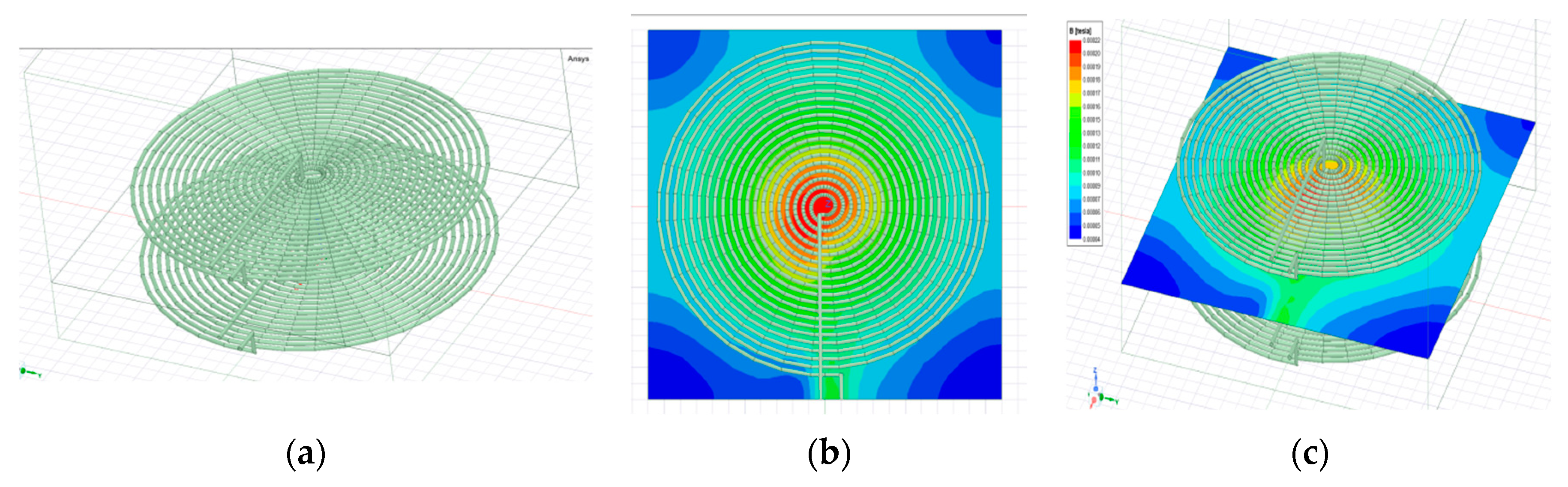
 Circular [48] |
|  Square [49] |
|
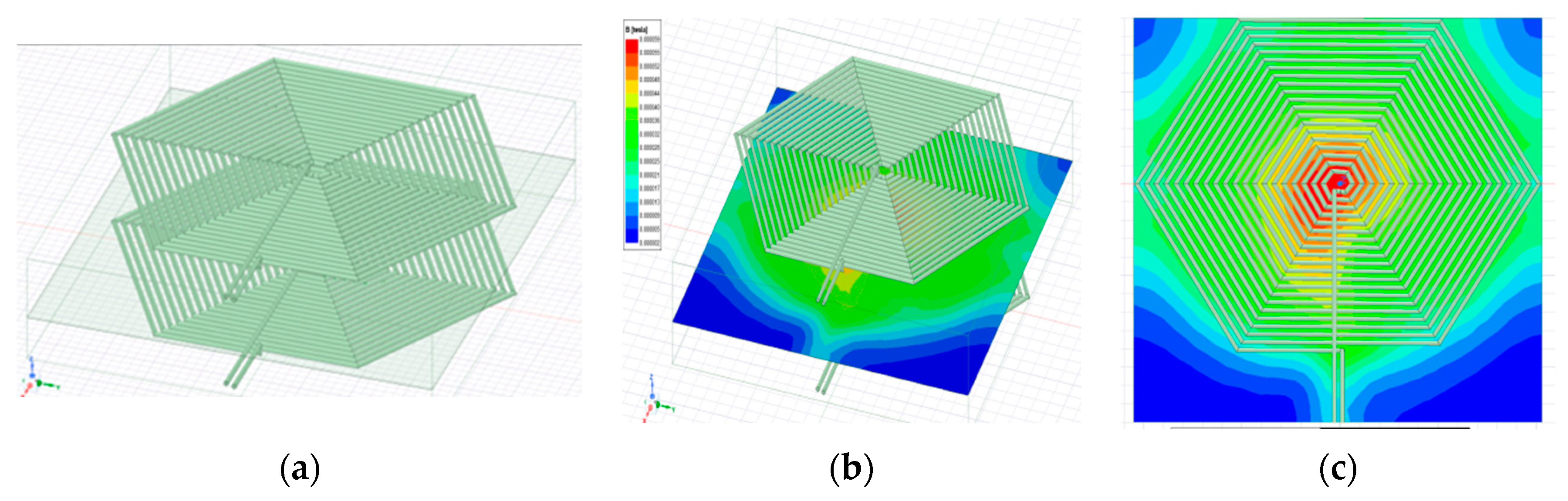
 Hexagonal [50] |
|  Rectangular [51] |
|
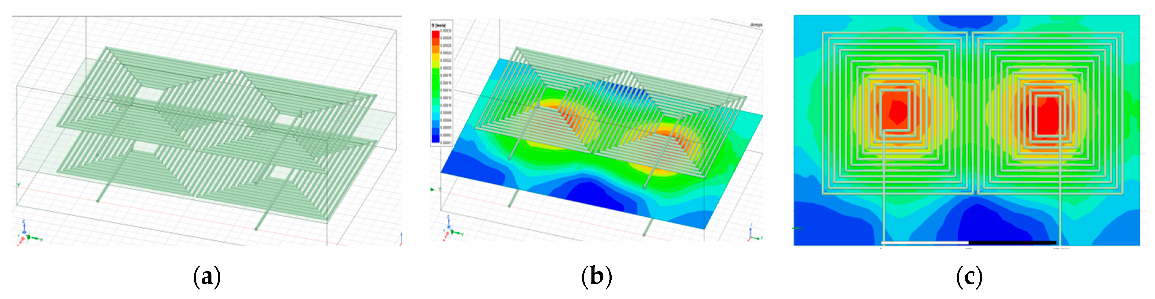
 Double D [52] |
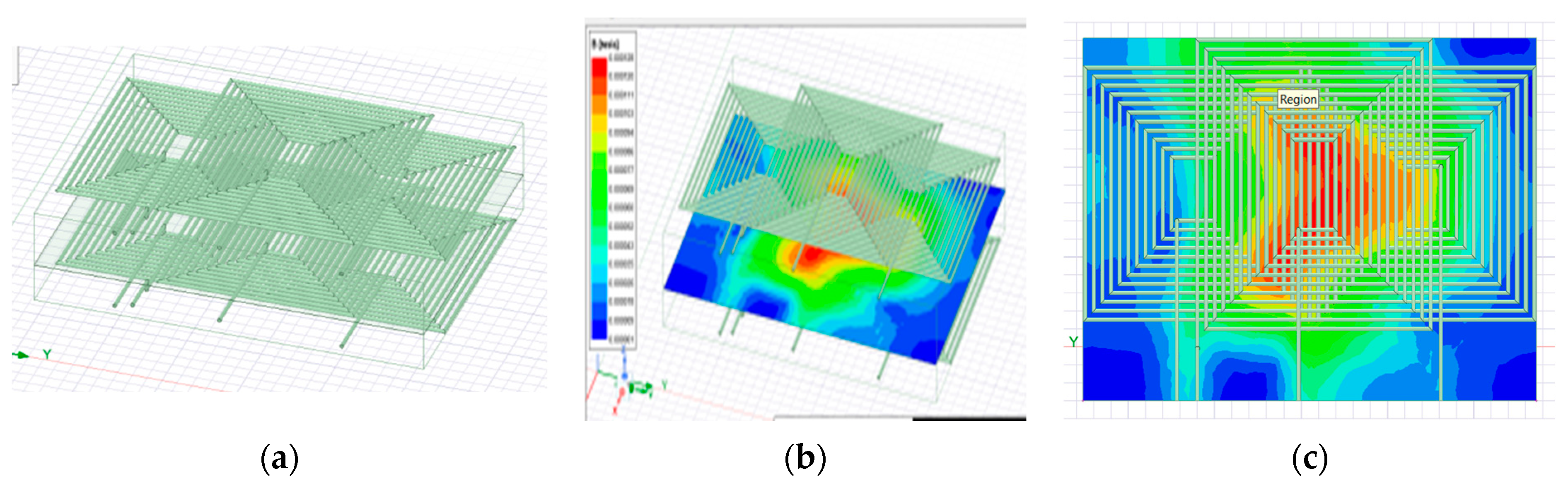
|  Double D Quadrature [53] |
|
 Bipolar [54] |
|  Quadrapule [55] |
|
 Flux pipe [56] |
|  Tri-polar [57] |
|
| Parameters | Misalignment | Interoperability | Leakage Flux | Coupling Range | Efficiency (%) |
|---|---|---|---|---|---|
| Rectangular | Intermediate | Low | Intermediate | Low | 75–90 |
| Circular | Poor | Very Low | High | Low | 85–95 |
| Hexagonal | Good | Low | Low | Intermediate | >90 |
| DD Coil | Intermediate | Non-interoperable | Poor | Intermediate | >90 |
| DDQ Coil | High | High | Poor | High | 91–95 |
| Quantity | Objectives |
|---|---|
| Objectives of Control System |
|
| Objectives of Detection System |
|
| Objectives of Power Converters |
|
| Parameters of Grid Integration |
|
| Parameters in Charging Couplers |
|
| Objectives of Compensation Network |
|
| Control Structure | Description | Applications | Advantages | Disadvantages |
|---|---|---|---|---|
| Inverter Control | Uses phase shift or frequency control, often with sinusoidal pulse width modulation (SPWM). | Most WPT and IPT systems | Simple structure, fewer components, smaller size | Limited to single-sided control |
| Impedance Matching (IM) | Uses capacitors, inductors, and switches to balance impedance mismatch. | High-frequency, low-power systems | Can balance impedance mismatch effectively | Bulky, complex, not suitable for changing loads |
| Dual-Side Active Bridge (DAB) | Employs independent control on both primary and secondary sides without feedback link. | Overcoming single-side drawbacks | Low conduction losses, independent control, power regulation | Large size, many semiconductor components |
| DC Level Control | Utilizes DC–DC converters (buck, boost, or buck–boost) on both primary and secondary sides. | Systems requiring independent control | Independent operation on both sides, no feedback link required | Complexity due to multiple converters |
Disclaimer/Publisher’s Note: The statements, opinions and data contained in all publications are solely those of the individual author(s) and contributor(s) and not of MDPI and/or the editor(s). MDPI and/or the editor(s) disclaim responsibility for any injury to people or property resulting from any ideas, methods, instructions or products referred to in the content. |
© 2024 by the authors. Licensee MDPI, Basel, Switzerland. This article is an open access article distributed under the terms and conditions of the Creative Commons Attribution (CC BY) license (https://creativecommons.org/licenses/by/4.0/).
Share and Cite
Ramesh, P.; Komarasamy, P.R.G.; Rajamanickam, N.; Alharthi, Y.Z.; Elrashidi, A.; Nureldeen, W. A Comprehensive Review on Control Technique and Socio-Economic Analysis for Sustainable Dynamic Wireless Charging Applications. Sustainability 2024, 16, 6292. https://doi.org/10.3390/su16156292
Ramesh P, Komarasamy PRG, Rajamanickam N, Alharthi YZ, Elrashidi A, Nureldeen W. A Comprehensive Review on Control Technique and Socio-Economic Analysis for Sustainable Dynamic Wireless Charging Applications. Sustainability. 2024; 16(15):6292. https://doi.org/10.3390/su16156292
Chicago/Turabian StyleRamesh, Pabba, Pongiannan Rakkiya Goundar Komarasamy, Narayanamoorthi Rajamanickam, Yahya Z. Alharthi, Ali Elrashidi, and Waleed Nureldeen. 2024. "A Comprehensive Review on Control Technique and Socio-Economic Analysis for Sustainable Dynamic Wireless Charging Applications" Sustainability 16, no. 15: 6292. https://doi.org/10.3390/su16156292
APA StyleRamesh, P., Komarasamy, P. R. G., Rajamanickam, N., Alharthi, Y. Z., Elrashidi, A., & Nureldeen, W. (2024). A Comprehensive Review on Control Technique and Socio-Economic Analysis for Sustainable Dynamic Wireless Charging Applications. Sustainability, 16(15), 6292. https://doi.org/10.3390/su16156292