Article

Water and Wastewater Management in Production Processes of PGE Energia Ciepła SA Branch 1 in Krakow in Light of Company Modernization

by
Zbigniew Kowalczyk
1,* and
Wojciech Winiarski
2
1
Faculty of Production Engineering and Energetics, University of Agriculture in Krakow, ul. Balicka 116B, 30-149 Kraków, Poland
2
PGE Energia Ciepła S.A Department 1 in Krakow, 31-587 Kraków, Poland
*
Author to whom correspondence should be addressed.
Sustainability 2024, 16(15), 6686; https://doi.org/10.3390/su16156686
Submission received: 10 June 2024 / Revised: 21 July 2024 / Accepted: 2 August 2024 / Published: 5 August 2024

Abstract

:
Electricity production requires a very high water consumption. One way to reduce water demand in power plants might be effective wastewater recycling within the power plant, which can lead to almost zero wastewater discharge. The study aims to characterize the functioning of the water and wastewater management system before and after the modernization of a wastewater treatment installation owned by an electricity and heat producer using biomass and other solid fuels. The scope of work covered one of the largest energy companies in Poland: PGE Energia Ciepła SA Branch 1 in Krakow. Water management and the effectiveness of wastewater treatment installation modernization were assessed in terms of the BAT (Best Available Techniques) conclusions. Particular attention was paid to the analysis of changes in the quality parameters of wastewater after the modernization of the wet flue gas desulfurization installation. The research results prove that the modernization of the company’s water and wastewater system significantly reduced the emission of harmful substances into the environment and water consumption. After modernization, an effective reduction in the content of heavy metals and other pollutants in the wastewater was observed. A decrease in the content of cadmium was observed by 99%, nickel—96%, mercury—95%, and copper—83%.

1. Introduction

In times of increasing ecological awareness and the need to protect natural resources, the issue of effective water and wastewater management in the energy sector, and especially in thermal power plants, is becoming particularly important. Power plants and combined heat and power plants (CHP) are considered critical facilities in every region since they play a key role in energy and heat production processes. These facilities also depend on the availability of water, which is important especially in areas affected by water shortages. Nuclear power plants in particular consume significant amounts of water, i.e., from 20% to 83% more than coal-fired power plants of the same capacity [1]. Heat and power plants, as key links in energy systems, use water mainly for cooling purposes, technological processes, and steam production. At the same time, they are a source of industrial wastewater. Its appropriate treatment and management pose a challenge to the protection of the aquatic environment.
The fuel that is the dominant global fuel for electricity generation is coal. Although this electricity generation technology is characterized by a lower water demand compared to nuclear energy, its water consumption is so high that it burdens local water resources [2]. Coal-fired power plants provide over 70% of electricity in China [3]. According to the China Electricity Council, the water consumption of coal power plants in China was 3.5 km3, which represents 11% of the total industrial water consumption in this country. The average water consumption for coal power plants in China was 1.15 L/kWh. Approximately 75% of the water consumption of coal power plants occurs in water-stressed regions. The results suggest that the impact on regional water resources should be explicitly considered when planning coal power plants [4].
Thus, energy is a key element in water collection and distribution, and water is essential for energy production [5]. Moreover, both water and energy demands are likely to increase due to population growth in the near future [6]. For power plant operators, an important challenge is the ever-increasing risk of water shortages. Electricity shortages due to water shortages can impact both industry and private households [7]. Between 1950 and 2010, the rapid expansion of generating capacity increased global water consumption for power generation 18 times [8]. For example, in China the freshwater consumption per unit of electricity generation is 1.9 m3/MWh [9] and in Poland as much as 5623.1 cubic hectometers of water are used per year [10]. Due to critical water shortages in many areas around the world, it is necessary to create optimal solutions that take into account water consumption and the growing demand for electricity. This is to prevent further conflicts of interest between industry, households, and environmental goals. The contradiction between economic development and environmental protection is becoming more and more visible [11]. Currently, electricity production must compete in terms of water demand with other types of production and sectors of the economy, such as agriculture or consumption for social and sanitary purposes. Therefore, effective management of water resources becomes crucial for the industry to ensure sustainable development and stability of its operations [12]. Therefore, it is necessary to introduce water saving technologies. In recent years, there have been many different attempts to reduce and optimize water consumption in CHP plants. Unfortunately, water savings in air-cooled CHP installations are achieved at the expense of lower thermal efficiency and, consequently, higher intensity of carbon dioxide emission [8].
In the literature on the subject, there is the opinion that effective recycling of wastewater inside power plants could also reduce their water demand. This could lead to almost zero wastewater discharge and 40% water savings [13,14,15]. Moreover, the authors of [16] claim that one of the key challenges in water management in industry is wastewater disposal. Uncontrolled discharge of industrial wastewater into water bodies can cause pollution, leading to serious consequences for the environment and health [16]. To solve this problem, the industry is adopting various wastewater treatment technologies, including physical, chemical, and biological treatment [17]. The treatment of industrial wastewater from energy production and various industrial processes is crucial due to its potential impact on the environment and public health. Discharge of untreated or inadequately treated wastewater results in significant environmental, health, social, and economic costs [18]. Wastewater treatment installations, as a special type of production activity, prevent environmental and economic degradation caused by the direct discharge of raw wastewater into the environment [19]. However, wastewater treatment installations use energy and materials for their processes [20]. Therefore, wastewater treatment in CHP plants brings double environmental benefits. First, it protects the environment against contamination and, second, it allows the reduction of water consumption in technological processes.
In addition to the significant demand for water, a serious problem that coal-fired CHP plants face is air pollution from exhaust emissions. This is a significant problem that needs to be solved in the modern world due to the long-term planned consumption of fossil fuels. Therefore, reasonable and practical solutions must be adopted to reduce pollutant emissions [21]. The combustion of coal produces large amounts of pollutants (e.g., particulate matter (PM), nitrogen oxides (NOx), and sulfur oxides (Sox). This is why coal-fired power plants install flue gas purification systems to control and reduce pollutant emissions. Most current approaches to achieving ultra-low emissions in coal-fired power plants involve the use of the following methods: selective catalytic reduction (SCR), electrostatic precipitators (ESP), and wet flue gas desulfurization (WFGD) [4,22,23,24]. The issue of exhaust gas emissions and their purification methods is widely discussed in the literature, including by [3,22,25,26,27]. One of the most dangerous components of exhaust gases are sulfur compounds. It is common knowledge that SO2 emissions not only have a dangerous impact on human health and the ecosystem [28,29,30] but also hinder sustainable economic and social development [31,32]. The most effective desulfurization technique is the wet flue gas desulfurization (WFGD) using the lime–gypsum method, which requires the use of significant amounts of water.
Wet exhaust gas cleaning involves passing it through a solution or water suspension containing reacting agents that bind and neutralize sulfur compounds. It is estimated that in the wet flue gas desulfurization process, approximately 1 tonne of water is consumed per tonne of coal. Nevertheless, the more the amount of water increases in relation to exhaust gases (L/G—liquid/gas), the more the desulfurization efficiency gradually decreases [33]. The results of the research on WFGD were presented in their works by [34,35], among others. Effective methods to improve the performance of existing WFGD units are to increase the pH value and improve the liquid-to-gas ratio (L/G). However, in the case of a conventional limestone–gypsum WFGD system, appropriate pH values for limestone dissolution, SO2 absorption, and CaC3 oxidation are different. To balance the different demands, the pH of the circulating suspension is adjusted to be generally lower than 5.5 [36]. Flue gas purification in CHP power plants also involves significant water consumption and generates a significant amount of wastewater with a high heavy metal content. The amount of produced WFGD wastewater normally ranges from 15 to 20 kg/MW∙h [37]; therefore, the treatment of WFGD wastewater is a very important issue.
The current energy crisis means that the complete elimination of fossil fuels for energy and heat production could be postponed. Moreover, the rapid pace of industrialization, as well as urbanization, generates an increase in electricity consumption. This brings about direct consequences of environmental pollution [38,39]. Environmental regulations are very diverse worldwide. Unfortunately, there is a lack of up-to-date research in the literature on the water and wastewater management of CHP plants in Poland in the context of current environmental regulations.
The issue of water and wastewater management in light of environmental protection was the subject of research at PGE Energia Ciepła SA Branch 1 in Krakow. The aim of the research was as follows:
-
To analyze the general structure and functioning of the water and wastewater management system at PGE Energia Ciepła SA Branch 1 in Kraków, with particular emphasis on the process of preparing technological water and wastewater treatment.
-
To assess the effectiveness of the modernization of wastewater treatment installation with a wet flue gas treatment installation by analyzing changes in the quality parameters of wastewater after launching the installation.
-
To assess the significant impact of the treatment installation on ensuring compliance of wastewater parameters using applicable environmental standards, with particular emphasis on meeting the requirements of the BAT of July 2017 regarding the treatment of heavy metals from wastewater.
The scope of work covered the entire water and wastewater management in the company in the years 2020–2023, i.e., before and after modernization.

2. Materials and Methods

PGE Energia Ciepła SA is one of the Polish electricity and heat producers. It has a plant in Krakow, Branch 1. Cogeneration of energy and heat has been recognized worldwide as an effective and efficient way of using energy [40,41,42,43], and coal-fired power generation is an important approach to energy supply [2].
PGE Energia Ciepła SA produces over 70% of the heating supplied to the residents of Krakow. Table 1 shows the general characteristics of PGE Energia Ciepła SA in Krakow.
The basic generation units at PGE Energia Ciepła in Kraków are four power units and peak load water boilers. The combined heat and power plant produces electricity and heat by burning hard coal and biomass, and the product of the desulfurization of the flue gas is synthetic gypsum. The produced heat energy is transferred to the heating system of the city of Krakow, and electricity to the national power system. General information about the CHP plant and basic technical data of the installed devices is presented in Table 1. Water for the heat and power plant is taken from the Białucha River, and the plant itself is designed to purify the water before it is introduced into its system. This helps protect the devices and installations of CHP plants from the deposition of contaminants that could affect the efficiency of the devices or cause their damage. All of these functions of a CHP water treatment installation are to ensure adequate water quality and to maintain the efficiency and reliability of the cooling and steam generation systems. This is crucial for the efficient operation of the power plant and minimizing the impact on the natural environment [44].
In a CHP plant, the sources of air emissions of pollutants are power boilers in which the fuel combustion process takes place, and its products are emitted, i.e., nitrogen dioxide, sulfur dioxide, dust, carbon monoxide, carbon dioxide, benzoapyrene, hydrogen chloride, and fluorine. Emissions standards for the energy sector have changed over time due to growing interest in environmental protection and the need to reduce emissions of greenhouse gases and pollutants. Over the years, various regulations and standards have been introduced to improve air quality and reduce the impact of energy production on the environment. This resulted in the need to modernize the CHP plant. Flue gases from block boilers are purified using the following technologies:
  • Dust removal—electrostatic precipitators (dust collectors);
  • Flue gas desulfurization using the wet lime method;
  • Flue gas denitrification using selective noncatalytic flue gas denitrification (SNCR in boilers 1 and 2) and the catalytic method (SCR in boilers 3 and 4).
These installations allow compliance with environmental standards regarding emissions from the atmosphere, the permissible emission values of which are shown in Table 2.
For comparison, the permissible amount of air emissions for PGE Energia Ciepła in Krakow was before 17 August 2021: for SO2 and NOx—200 (mg · Nm−3), and for dust—20 (mg · Nm−3).
Table 3 shows the values of the new emission standard for treated wastewater for PGE Energia Ciepła in Krakow before and after the introduction of BAT regulations. When analyzing Table 3, it can be seen that the standards have been raised in the case of as many as 14 wastewater parameters. The limit value was lowered for 7 parameters, while it was newly set for 7 others (the standards did not take it into account before).
PGE Energia Ciepła SA complies with relevant standards and regulations in terms of environmental protection and has appropriate wastewater treatment systems. It is a plant that is aware of the need to minimize the impact of generated wastewater on the natural environment and regularly monitors its emissions to ensure compliance with regulations. On the premises of the studied CHP plant, there are two types of wastewater treatment installations that are adapted to the requirements of the BAT conclusions regarding permissible concentrations for industrial wastewater.
To assess the effectiveness of the installation, the quality of the wastewater was analyzed using the results of constant daily measurements. The basic parameters of the effluents and treated wastewater from the wet flue gas desulfurization installation were measured online, in continuous mode, and saved in the database. Additionally, chemical laboratory workers measured wastewater samples to control and verify automatic measurements. The results collected from each day were subjected to detailed analysis, and daily, monthly, annual averages, etc. were calculated. Such an analysis allowed the authors to obtain a coherent picture of the changes occurring over various periods. It also allowed identifying long-term trends and changes in test results while eliminating any possible fluctuations in a shorter time interval. The deviations of the measured values in the individual samples were not large and did not exceed the limit values. Monthly measurement results of treated wastewater are sent to the Provincial Office of Environmental Protection and are used for settlement in accordance with the so-called integrated permit. They are performed by a certified third-party laboratory. The measurement of pollutants took place in accordance with Polish law, using the detailed methodology presented in the Regulation on substances particularly harmful to the aquatic environment and the conditions to be met when discharging waste water to waters or to the ground, as well as when discharging rainwater or snowmelt to waters or to water installations [45]. During physical and chemical analyzes, special attention was paid to the content of heavy metals, chemicals, and other pollutants listed in the BAT conclusion in an average daily sample of wastewater treated from the wet flue gas desulfurization installation. The adopted research methodology made it possible to compare the results of wastewater treated from wet flue gas desulfurization installation before and after the modernization of the wastewater treatment installation, and thus to analyze changes in the quality parameters of wastewater after the modernization of the installation.

3. Results and Discussion

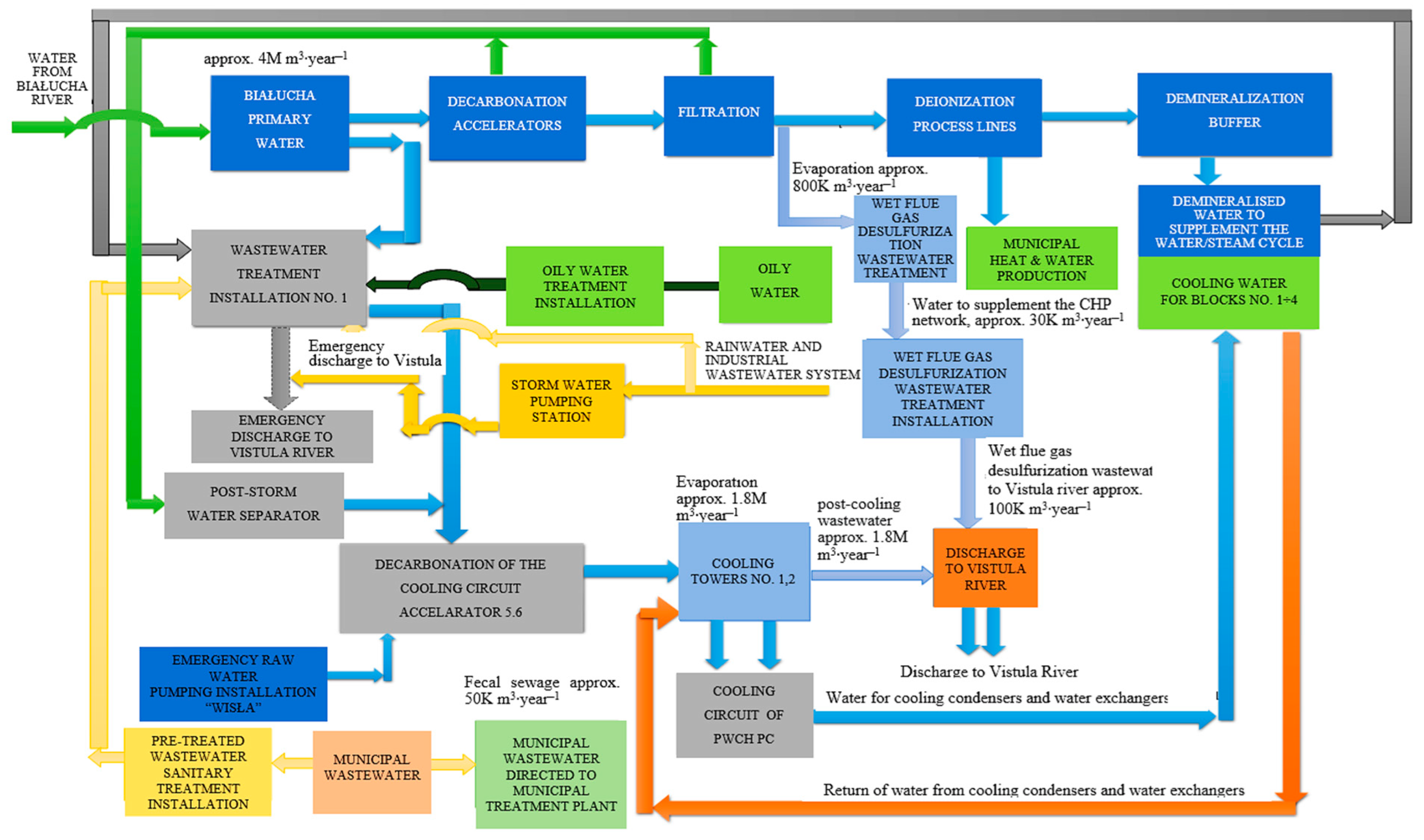
3.1. Water Management

Water and wastewater management in production processes is a key aspect in industrial activities, especially in the energy sector. PGE Energia Ciepła SA takes important steps to effectively manage water resources, minimizing the impact on the environment. The company implements water and wastewater management procedures and systems to ensure a sustainable and effective use of water resources.
Figure 1 shows a block diagram of the water and wastewater system in the Krakow CHP plant. The plant draws approximately 3–4 million m3 of water annually from the Białucha River for its own needs, depending on the amount of heat and electricity produced. Water can also be drawn from the Vistula River to be treated and used for the cooling circuit, but this is considered an emergency measure due to the unfavorable parameters of this water. Another emergency source of the water necessary for the boiler and the heating circuit is the municipal water supply network, but it is not used for economic reasons. The water treatment installation at the CHP plant primarily helps to remove chemicals, heavy metals, and other pollutants that could hinder or prevent ongoing technological processes or could be released into the environment. Water from the installation is used for several purposes. The first is the cooling process, as a thermal power plant requires a significant amount of water to cool various systems, such as steam condensers or generators. The second purpose is to supply water to steam boilers, where the water is heated to produce steam. Water treatment processes remove contaminants such as sediments, organic compounds, and mineral salts that could lead to corrosion or serious boiler faults. Additionally, the plant uses its own treated wastewater and reintroduces it into the production process. Please note that the quality of treated wastewater is higher than the quality of the water available in the Vistula River. Its use in the cooling system significantly reduces the consumption of surface water.
The water pre-treatment installation is based on water decarbonization with lime milk and coagulation with PIX. Raw water from the Białucha River is directed to the accelerators: AKC1, AKC2, and AKC3 (Figure 2) where decarbonization processes take place. A 2% solution of lime milk and a coagulant (ferric sulfate PIX-113) are added to the water in the reaction chamber. As a result of the process, the compounds that cause carbonate hardness in raw water are reduced. The process that supports mechanical water purification is coagulation.
The next stage of decarbonized water treatment is filtration. Decarbonized water is filtered in gravel filters FŻ, operating in parallel (Figure 3). These filters remove suspension residues from decarbonized water. Wastewater from filter rinsing is directed to post-decarbonization plots and then to the wastewater treatment installation.
The next stage of water treatment is deionization. After filtering using gravel filters, the water is directed directly to strongly acidic cation exchangers, K1, K2, and K3, working in parallel (Figure 4). The ion exchange process in the cation exchange bed involves the exchange of metal cations from salts dissolved in water for hydrogen cations present in the cation exchanger. After the exchange, water is then transferred to double-layer anion exchangers—A1, A2, and A3 (Figure 4). These exchangers are filled with two types of anion exchangers: weakly basic and strongly basic, forming two separate layers. The purpose of the weakly alkaline mass is to exchange the anions of strong acids (coming from salts dissolved in water) with the hydroxide anions OH.
The next stage is to redirect the deionized water to storage tanks—V1000 No. 1, V1000 No. 2, and V4000 No. 3. From there, it passes through the distribution system to supplement the heating network of the city of Krakow and power the double-ion exchangers.
The last stage of the water preparation process is simultaneous demineralization carried out in three double-ion exchangers—AK1, AK2, and AK3—operating in parallel (Figure 4). The exchangers are to ultimately correct water quality parameters by removing trace amounts of ions that are not retained by the preceding cation exchangers and anion exchangers. Each dual-ion exchanger contains a bed of a mixed strongly acidic cation exchanger and strongly basic anion exchanger. Then, demineralized water is stored in three tanks—V300 No. 1, V300 No. 2, and V300 No. 3—and directed to supplement the boiler circuit.

3.2. Wastewater Management

PGE Energia Ciepła in Krakow manages wastewater that is generated at the plant as a result of production and social activity. Currently, several types of wastewater are produced at the plant:
-
General plant wastewater is directed to the industrial-rainwater treatment installation no. 1 (Figure 1). After treatment, it is returned for reuse in the cooling water circuit.
-
Wastewater from flue gas desulfurization by the wet lime method, which is discharged into the Vistula River after treatment in the installation (approximately 100,000 m3 annually) (Figure 1).
-
Post-cooling wastewater (desalt) from the closed circulation of water that cools turbine sets, which is discharged into the Vistula River (approximately 1M m3 annually) (Figure 1).
-
Sanitary (social) wastewater, which is partly directed to the municipal wastewater system, and partly treated in the Imhoff sedimentation tank and directed to the company’s industrial-rainwater wastewater system (Figure 1).

3.2.1. Industrial and Storm Wastewater Treatment Installation No. 1

Figure 5 shows a diagram of the wastewater treatment installation no. 1 with a reserve pumping station for water from the Vistula River. The following types of wastewater are discharged to the treatment installation:
-
Desalt from the boiler circuit;
-
Emergency and maintenance heating water drains;
-
Drainage and leaks from the main building;
-
Wash-off wastewater and drainage water treated in a three-chamber settling tank;
-
Wastewater from oil management treated in an oily wastewater treatment installation;
-
Wastewater from water treatment installation (post-decarbonization) for the boiler and heating circuits;
-
Infiltration and drainage waters;
-
Rainwater and meltwater;
-
Sanitary wastewater from the eastern area of the plant treated in an Imhoff settling tank.
All the types of wastewater mentioned above flow gravitationally through grates to the intake chamber of the dirty wastewater pumping station. Then, they are pumped to three sedimentation tanks (Figure 5). In the settling tanks, the wastewater is cleaned of easily settling suspensions. Then, it flows by gravity to the intake chamber of the purified wastewater pumping station, and from there it is pumped to complete the cooling water circuit. Sediments accumulated in sedimentation tanks are regularly removed after dewatering. Wastewater treatment installation no. 1 is of mechanical type. Therefore, the only water circuit in which purified industrial wastewater and rainwater can be used is the cooling circuit supplemented with surface water.

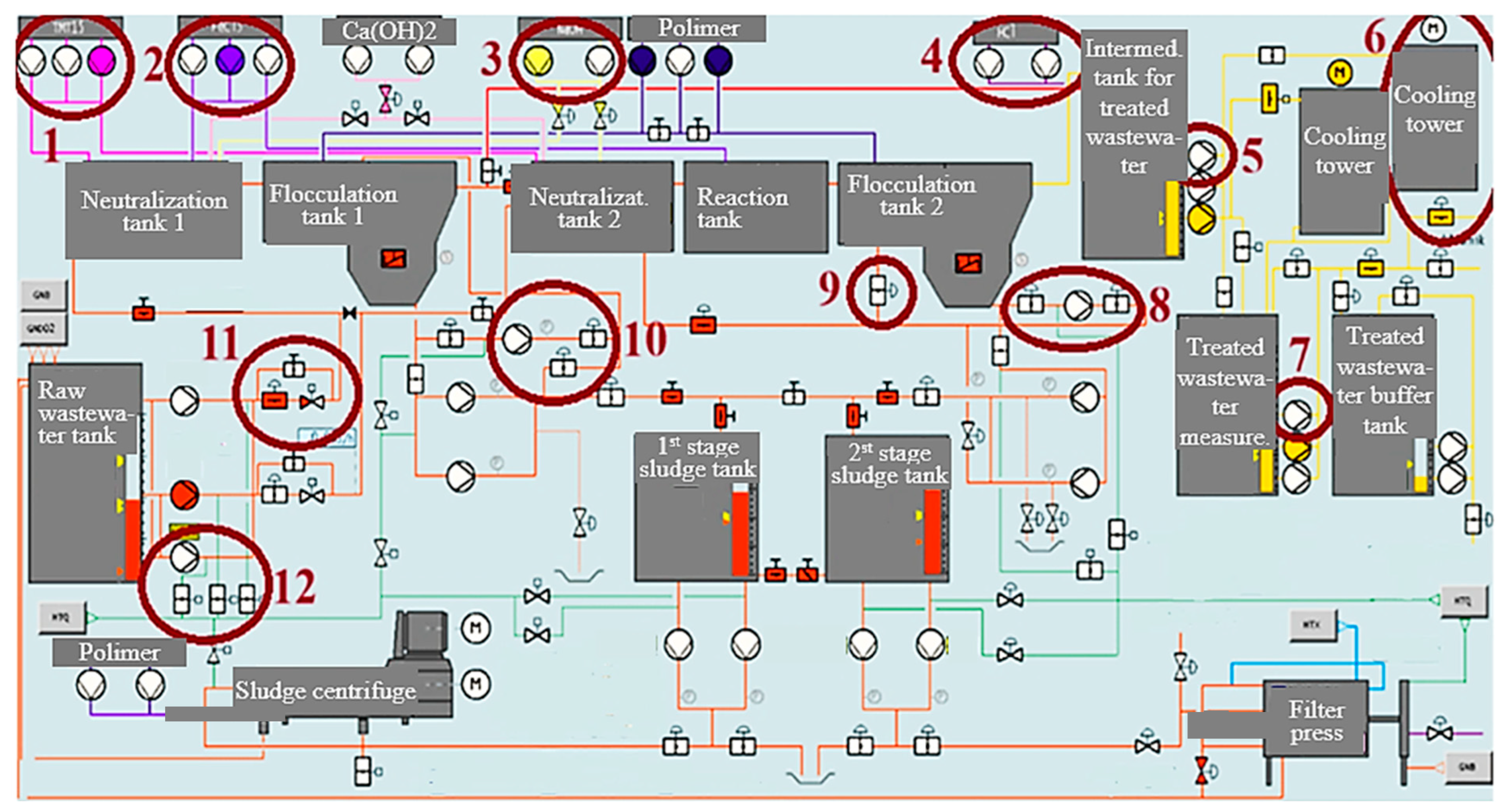
3.2.2. Wet Flue Gas Wastewater Treatment Installation

Flue gas desulfurization using the wet-lime method involves washing the dedusted flue gases with a water sorption suspension containing mainly calcium carbonate CaCO3 [35]. To achieve a high efficiency of the wet flue gas desulfurization installation, part of the circulating absorption solution in the form of wastewater must be removed, but not more than 50 m3/h. Raw wastewater from the flue gas desulfurization process using the wet lime method is characterized by an acidic reaction, a high content of mineral suspensions, a very high content of dissolved substances, mainly chlorides, sulfates, sodium, and potassium nitrates, and an increased content of heavy metals. Figure 6 shows a diagram of the wet flue gas desulfurization wastewater treatment installation before modernization. Wastewater is supplied to the treatment installation from the intermediate raw wastewater tank, which is fed from the overflow of the wastewater hydrocyclone battery. In addition to the main wastewater stream from the wet flue gas desulfurization installation, circulating purified wastewater is also directed to the raw wastewater tank in the following cases:
-
When the quality of treated wastewater does not meet the required parameters;
-
When the concentration of suspension directed to individual stages of the wastewater treatment installation must be reduced;
-
During periods of shutdown of wet flue gas desulfurization installation absorbers, to maintain continuous operation of the wastewater treatment installation; the amount must at least be equal to the minimum capacity of the installation.
In the event of a failure, the wastewater can be retained in the buffer tank for up to 8 h.
Wastewater produced by wet flue gas desulfurization installation is treated at individual technological stages (Figure 6 and Figure 7). The first stage is neutralization and the formation of a precipitate with a small amount of heavy metals (1st stage), which takes place in the neutralization tank (1st stage reactor). The process of precipitation of suspensions and pollutants dissolved in wastewater is initiated there. Wastewater with a pH of 6.6–6.8 with a high content of solids is fed to the neutralization tank no. 1, to which milk of lime or sodium hydroxide (NaOH) is dosed to raise the pH to 7–8. A heavy metal precipitation agent NALMET is dosed proportionally to the flow of raw wastewater of neutralization tank no. 1 (to precipitate difficult-to-precipitate metals), along with a coagulant (ferric sulfate PIX-113) to improve the precipitation of contaminants found in wastewater. Deposition of pollutants precipitated in the neutralization tank takes place in the 1st stage sedimentation tank. Part of the precipitated sludge is recirculated to the neutralization tank as contact sludge. The remaining part goes to the sludge dewatering plant.
From the neutralization tank, the wastewater flows gravitationally to the flocculation tank no. 1 (1st stage) integrated with the lamella settling tank no. 1, where it reacts with the dosed polymer. As a result, well-settling flocks are formed. To improve the wastewater treatment process, part of the sludge is recirculated from lamella no. 1 to flocculation tank no. 1 (ready-made flocks are introduced into the process). Control valves dose polymer to promote flocculation in proportion to the raw wastewater flow.
The overflow from the lamella settling tank no. 1 is fed gravitationally to the neutralization tank no. 2, where the wastewater reacts with lime milk or sodium hydroxide. The control valves dose sodium hydroxide or lime milk in proportion to the raw wastewater flow and depending on the pH value. The pH value is set at 8.5 and is favorable for the precipitation of most heavy metals from the wet flue gas desulfurization treatment installation. Not all heavy metals (e.g., mercury and cadmium) can be precipitated as hydroxides. Therefore, the NALMET heavy metal precipitation agent is dosed into the neutralization tank 2 in proportion to the raw wastewater flow using a dosing pump. It forms primarily sparingly soluble complex compounds with mercury and cadmium.
The wastewater from the overflow of lamella no. 1 contains a lot of small particles that do not settle well. To improve the coagulation of solids, ferric sulfate PIX-113 is dosed into the reaction tank. The ability of the sludge to settle is improved by dosing the polymer into flocculation tank no. 2 (2nd stage). Mixers in individual chambers are used to thoroughly mix individual reagent streams. The solids that precipitated in the flocculation tank no. 2 flow gravitationally to the lamella settling tank no. 2 with inclined walls. Baffles are mounted on the inner walls of this tank to increase the effective clarification surface. This is where the solids are separated. Part of the precipitated sludge is recirculated into the reactor tank as contact sludge. The remaining part goes to the sludge dewatering plant. The purified and clarified wastewater flows through an overflow gutter to the intermediate purified wastewater tank. In the intermediate tank of treated wastewater, the pH is corrected with HCl to a value of 8.8 pH. In the event of a failure, the wastewater can be retained for up to 8 h. The wastewater is directed to the fan cooling towers through the treated wastewater tank. Then, it is pumped into cooling towers, where it is cooled to a standard temperature below 35 °C. From there, the wastewater is directed through a measuring chamber to the treated wastewater retention tank and then to the collector, which discharges the wastewater into the Vistula River.
Figure 7 shows a diagram of the wet flue gas desulfurization wastewater treatment installation before modernization. As part of its modernization, the node operating system was re-built from serial to parallel to increase efficiency. The automation, measurement, and chemical dosing systems were also modernized. To adapt the installation to the requirements of the BAT conclusions regarding permissible concentrations for wastewater from the wet flue gas desulfurization treatment installation, a wastewater treatment technology was implemented involving the use of the NALMET preparation that binds metals contained in wastewater. In addition, sodium hydroxide was used as a reagent that optimizes the precipitation of metals and heavy metalloids.
Figure 7 presents a detailed list of devices and installations that were introduced during the modernization of the wet flue gas desulfurization wastewater treatment installation. The modernization included the following:
  • Changing the reagent for precipitation of heavy metals (NALMET) and installing an additional pump set;
  • Installing an additional pump set to dose the PIX-113 coagulant;
  • Installing additional pump sets to dose NaOH (pH correction);
  • Installing additional pump sets to HCL (pH correction);
  • Using an additional pump set attached to the intermediate tank of treated wastewater;
  • Installing an additional cooling tower;
  • Installing an additional pump set attached to the measuring tank of treated wastewater;
  • Installing a pump set with fittings as part of the flocculation tank no. 2;
  • Installing an additional valve under the flocculation tank no. 2;
  • Installing an additional pump set with fittings as part of the flocculation tank no. 1;
  • Using additional fittings as part of the raw wastewater tank;
  • Installing an additional pump set with fittings as part of the raw wastewater tank.
Please note also that as part of the modernization of exhaust gas purification technology, electrostatic precipitators were modernized. This improved the quality of exhaust gases entering the absorber, reducing the dust content from 100 mg∙Nm−3 to below 30 mg∙Nm−3. An additional sieve shelf was also installed in the absorber of the wet flue gas desulfurization wastewater treatment installation. This led to better dedusting of exhaust gases, i.e., even more ash was separated from the exhaust gases during SO2 reduction. This meant that there was no need for additional modernization of the electrostatic precipitator, e.g., by adding an additional dedusting zone, or using other methods, e.g., bag methods, to meet dust emission standards of 8 (mg∙Nm−3). The above changes also reduced water consumption in the wet flue gas desulfurization wastewater treatment installation (estimated at several percent), as well as consumption of chemicals needed for raw water treatment, such as acid, lye, and lime.
Wastewater from the wet flue gas desulphurization system is characterized by a high content of inorganic compounds in the form of salts, primarily gypsum. Salinity can be above 20,000 mg/L chlorides and 2000 mg/L sulfates (VI). In addition, heavy metals and organic compounds are also present in wastewater. The main factors influencing the quality and quantity of wastewater generated are the parameters of the coal, combustion, and the FGD system hydraulic load [49]. Table 4 shows the results of the quality parameter test of wastewater in the years 2020, 2022, and 2023, i.e., before and after the modernization of the wet flue gas desulfurization wastewater treatment installation. The data presented are based on the results of daily measurements. Please note that in connection with the BAT conclusion, the table also includes additional wastewater pollution parameters, which were not covered by previous standards, and which must be monitored and complied with after the changes in regulations. Following the analysis of Table 4, it can be concluded that the modernization of the wastewater treatment installation brought very positive effects. As many as 12 parameters were improved, i.e., their values were reduced. The greatest reduction was achieved for particularly dangerous heavy metals, such as mercury, cadmium, zinc, copper, nickel, and lead. For example, a decrease in cadmium content was observed by 99%, nickel 96%, mercury 95%, and copper 83%. Slightly lower decreases, although also significant, were observed in suspended solids 75% and zinc 67%. Without the modernization of wastewater treatment installation, the values of parameters relating to heavy metals in wastewater would exceed the new standards introduced. The slightly higher pH value in 2022 and 2023 compared to 2020 is caused by lower-quality coal burned in boilers caused by the energy crisis and problems with access to good-quality raw material on the market. A similar situation occurs when the content of total nitrogen and sulphite increases, but please note that despite the increase in pH and the content of nitrogen and sulphite, these values were still within the standards. The higher content of lead in treated wastewater after the modernization of the installation is not due to the actually increased content of this element but to the calculation methodology. The measurement results were so low that they were below the limit of determination of the given substance. In such a situation, in accordance with [50] Directive 2009/90/EC of 31 July 2009, the practice of setting measurement results at half the value of the limit of determination is used. It can be seen that for most parameters, their average values measured in different years are well below the limit values. Only temperature is close to the limit values and lead slightly exceeded it in 2022, as explained above.

4. Conclusions

The recent energy crisis, caused by the geopolitical situation, has increased interest in conventional energy sources. At the same time, the environmental requirements for the burning of coal and other fossil fuels are constantly increasing. The above situation increases the search for new technologies for generating heat and electricity from fossil fuels that would be environmentally friendly and meet increasingly stringent environmental standards. In CHP plants, the problem of environmental pollution applies not only to air but also to wastewater. At the same time, CHP plants use very large amounts of water in production processes, which is not without consequence for the natural environment. In the PGE Energia Ciepła CHP plant in Krakow, water and wastewater is managed with great care for the natural environment. Basic wastewater parameters are constantly monitored online and recorded in the database. Additionally, collected wastewater samples are sent to the chemical laboratory for additional control and verification of automatic measurements.
To meet standards consistent with the new BAT conclusion regarding permissible concentrations for industrial wastewater, it was necessary to modernize the wet flue gas desulfurization wastewater treatment installation. The research on the quality of wastewater from the wet flue gas desulfurization installation at the PGE Energia Ciepła heat and power plant in Krakow, before and after its modernization, was to determine the impact of changes on the quality parameters of wastewater and meeting the new BAT standards for wastewater emissions.
Due to the modernization of the wastewater treatment installation, the heat and power plant successfully meets the new BAT standards for wastewater emissions, despite the significant restriction of purified wastewater emission standards after the introduction of BAT regulations (for as many as 14 parameters). After modernization, an effective reduction in the content of heavy metals and other pollutants in the wastewater was observed. A decrease in cadmium content was observed by 99%, nickel 96%, mercury 95%, and copper 83%. As part of the technology modernization, the consumption of process water, electricity, and chemicals (acid, lye, and lime needed for raw water treatment) used to purify flue gases and wastewater was reduced. The changes introduced not only reduce operating costs, but also contribute to environmental protection by reducing energy consumption and greenhouse gas emissions. Despite the satisfactory results, the quality parameters of wastewater must be further monitored. It is crucial to continuously assess the effectiveness of treatment systems and to maintain compliance with emission standards.

Author Contributions

Conceptualization, Z.K. and W.W.; methodology, W.W.; validation, W.W.; formal analysis, Z.K. and W.W.; investigation, W.W.; resources, W.W.; writing—original draft preparation, Z.K. and W.W.; writing—review and editing, Z.K. All authors have read and agreed to the published version of the manuscript.

Funding

The Publication was co-financed from the funds of the Ministry of Education and Science under the contract No. KONF/SP/0507/2023/01 dated 13.01.2024 in the amount of 92113.85 PLN.

Institutional Review Board Statement

Not applicable.

Informed Consent Statement

Not applicable.

Data Availability Statement

The original contributions presented in the study are included in the article, further inquiries can be directed to the corresponding author.

Acknowledgments

Publication was supported with a grant from the Ministry of Education and Science of the Republic of Poland.

Conflicts of Interest

Wojciech Winiarski was employed by the company PGE Energia Ciepła SA Branch 1 in Krakow. The remaining authors declare that the research was conducted in the absence of any commercial or financial relationships that could be construed as a potential conflict of interest.

References

  1. Khamis, I.; Kavvadias, K.C. Trends and challenges toward efficient water management in nuclear power plants. Nucl. Eng. Des. 2012, 248, 48–54. [Google Scholar] [CrossRef]
  2. Zhang, X.; Liu, J.; Tang, Y.; Zhao, X.; Yang, H.; Gerbens-Leenes, P.W.; Yan, J. China’s coal-fired power plants impose pressure on water resources. J. Clean. Prod. 2017, 161, 1171–1179. [Google Scholar] [CrossRef]
  3. Li, Z.; Jiang, J.; Ma, Z.; Wang, S.; Duan, L. Effect of selective catalytic reduction (SCR) on fine particle emission from two coal-fired power plants in China. Atmos. Environ. 2015, 120, 227–233. [Google Scholar] [CrossRef]
  4. Zhang, Y.; Yang, J.; Yu, X.; Sun, P.; Zhao, Y.; Zhang, J.; Chen, G.; Yao, H.; Zheng, C. Migration and emission characteristics of Hg in coal-fired power plant of China with ultra low emission air pollution control devices. Fuel Process Technol. 2017, 158, 272–280. [Google Scholar] [CrossRef]
  5. DeNooyer, T.A.; Peschel, J.M.; Zhang, Z.; Stillwell, A.S. Integrating water resources and power generation: The energy–water nexus in Illinois. Appl. Energy 2016, 162, 363–371. [Google Scholar] [CrossRef]
  6. Zhang, X.; Han, L.; Wei, H.; Tan, X.; Zhou, W.; Li, W.; Qian, Y. Linking urbanization and air quality together: A review and a perspective on the future sustainable urban development. J. Clean. Prod. 2022, 346, 130988. [Google Scholar] [CrossRef]
  7. Koch, H.; Vögele, S. Dynamic modelling of water demand, water availability and adaptation strategies for power plants to global change. Ecol. Econ. 2009, 68, 2031–2039. [Google Scholar] [CrossRef]
  8. Zhang, C.; Anadon, L.D.; Mo, H.; Zhao, Z.; Liu, Z. Water−carbon trade-off in China’s coal power industry. Environ. Sci. Technol. 2014, 48, 11082–11089. [Google Scholar] [CrossRef] [PubMed]
  9. Jin, Y.; Wang, L.; He, D. Water consumption of electric power system in China: From electricity generation to consumption. Environ. Sci. Pollut. Res. 2023, 30, 101903–101910. [Google Scholar] [CrossRef] [PubMed]
  10. Ochrona Środowiska 2022; Główny Urząd Statystyczny: Warszawa, Poland, 2022.
  11. Li, P.; Hu, Q.; Sun, Y.; Han, Z. Thermodynamic and economic performance analysis of heat and power cogeneration system based on advanced adiabatic compressed air energy storage coupled with solar auxiliary heat. J. Energy Storage 2021, 42, 103089. [Google Scholar] [CrossRef]
  12. Colella, M.; Ripa, M.; Cocozza, A.; Panfilo, C.; Ulgiati, S. Challenges and opportunities for more efficient water use and circular wastewater management. The case of Campania Region, Italy. J. Environ. Manag. 2021, 297, 113171. [Google Scholar] [CrossRef] [PubMed]
  13. Jain, R.; Nigam, H.; Mathur, M.; Malik, A.; Arora, U.K. Towards green thermal power plants with blowdown water reuse and simultaneous biogenic nanostructures recovery from waste. Resour. Conserv. Recycl. 2021, 168, 105283. [Google Scholar] [CrossRef]
  14. Liu, J. Analysis on Water Saving Effect of “Zero Discharge” Wastewater from 4 × 300MW Coal-fired Power Plants. IOP Conf. Ser. Environ. Earth Sci. 2021, 631, 1. [Google Scholar] [CrossRef]
  15. Han, X.; Yuan, T.; Zhang, D.; Dai, Y.; Liu, J.; Yan, J. Waste heat utilization from boiler exhaust gases for zero liquid discharge of desulphurization wastewater in coal-fired power plants: Thermodynamic and economic analysis. J. Clean. Prod. 2021, 308, 127328. [Google Scholar] [CrossRef]
  16. Tong, Y.; Huang, Z.; Janssen, A.B.; Wishart, M.; He, W.; Wang, X.; Zhao, Y. Influence of social and environmental drivers on nutrient concentrations and ratios in lakes: A comparison between China and Europe. Water Res. 2022, 227, 119347. [Google Scholar] [CrossRef] [PubMed]
  17. Xu, A.; Wu, Y.H.; Chen, Z.; Wu, G.; Wu, Q.; Ling, F.; Hu, H.Y. Towards the new era of wastewater treatment of China: Development history, current status, and future directions. Water Cycle 2020, 1, 80–87. [Google Scholar] [CrossRef]
  18. Hernandez-Sancho, F.; Lamizana-Diallo, B.; Mateo-Sagasta, J.; Qadir, M. Economic Valuation of Wastewater: The Cost of Action and the Cost of No Action; UN Environment Programme: Nairobi, Kenya, 2015; p. 68. [Google Scholar]
  19. Singh, B.J.; Chakraborty, A.; Sehgal, R. A systematic review of industrial wastewater management: Evaluating challenges and enablers. J. Environ. Manag. 2023, 348, 119230. [Google Scholar] [CrossRef] [PubMed]
  20. Dong, X.; Zhang, X.; Zeng, S. Measuring and explaining eco-efficiencies of wastewater treatment plants in China: An uncertainty analysis perspective. Water Res. 2017, 112, 195–207. [Google Scholar] [CrossRef] [PubMed]
  21. Smaisim, G.F.; Abed, A.M.; Alavi, H. Analysis of pollutant emission reduction in a coal power plant using renewable energy. Int. J. Low-Carbon. Technol. 2023, 18, 38–48. [Google Scholar] [CrossRef]
  22. Pudasainee, D.; Seo, Y.C.; Sung, J.H.; Jang, H.N.; Gupta, R. Mercury co-beneficial capture in air pollution control devices of coal-fired power plants. Int. J. Coal Geol. 2017, 170, 48–53. [Google Scholar] [CrossRef]
  23. Zhao, S.L.; Duan, Y.; Chen, L.; Li, Y.; Yao, T.; Liu, S.; Liu, M.; Lu, J. Study on emission of hazardous trace elements in a 350 MW coal-fired power plant. Part 1 Mercury. Environ. Pollut. 2017, 229, 863–870. [Google Scholar] [CrossRef] [PubMed]
  24. Yokoyama, T.; Asakura, K.; Matsuda, H.; Ito, S.; Noda, N. Mercury emissions from a coal-fired power plant in Japan. Sci. Total Environ. 2000, 259, 97–103. [Google Scholar] [CrossRef] [PubMed]
  25. Zhang, Y. Fine particles characteristics of ultra-low emission coal-fired power plants. In Advances in Ultra-Low Emission Control Technologies for Coal-Fired Power Plants; Woodhead Publishing: Sawston, UK, 2019; pp. 159–197. [Google Scholar]
  26. Beretta, A.; Usberti, N.; Lietti, L.; Forzatti, P.; Di Blasi, M.; Morandi, A.; La Marca, C. Modeling of the SCR reactor for coal-fired power plants: Impact of NH3 inhibition on Hg0 oxidation. Chem. Eng. J. 2014, 257, 170–183. [Google Scholar] [CrossRef]
  27. George, A.; Shen, B.; Kang, D.; Yang, J.; Luo, J. Emission control strategies of hazardous trace elements from coal-fired power plants in China. J. Environ. Sci. 2020, 93, 66–90. [Google Scholar] [CrossRef] [PubMed]
  28. Chen, R.J.; Huang, W.; Wong, C.M.; Wang, Z.; Thach, T.Q.; Chen, B.; Kan, H. Short-term exposure to sulfur dioxide and daily mortality in 17 Chinese cities: The China air pollution and health effects study (CAPES). Environ. Res. 2012, 118, 101–106. [Google Scholar] [CrossRef] [PubMed]
  29. Han, P.; Mei, H.; Liu, D.; Zeng, N.; Tang, X.; Wang, Y.; Pan, Y. Calibrations of low-cost air pollution monitoring sensors for CO, NO2, O3, and SO2. Sensors 2021, 21, 256. [Google Scholar] [CrossRef] [PubMed]
  30. Jion, M.M.; Jannat, J.N.; Mia, M.Y.; Ali, M.A.; Islam, M.S.; Ibrahim, S.M.; Islam, A.R.M.T. A critical review and prospect of NO2 and SO2 pollution over Asia: Hotspots, trends, and sources. Sci. Total Environ. 2023, 876, 162851. [Google Scholar] [CrossRef] [PubMed]
  31. Xing, Z.C.; Wang, J.; Feng, K.S.; Hubacek, K. Decline of net SO2 emission intensity in China’s thermal power generation: Decomposition and attribution analysis. Sci. Total Environ. 2020, 719, 137367. [Google Scholar] [CrossRef] [PubMed]
  32. Zhang, Q.; He, K.; Huo, H. Cleaning Chinas air. Nature 2012, 484, 161–162. [Google Scholar] [CrossRef] [PubMed]
  33. Ma, S.C.; Chai, J.; Jiao, K.L.; Ma, L.; Zhu, S.J.; Wu, K. Environmental influence and countermeasures for high humidity flue gas discharging from power plants. Renew. Sustain. Energy Rev. 2017, 73, 225–235. [Google Scholar]
  34. Hsu, C.J.; Atkinson, J.D.; Chung, A.; Hsi, H.C. Gaseous mercury re-emission from wet flue gas desulfurization wastewater aeration basins: A review. J. Hazard. Mater. 2021, 420, 126546. [Google Scholar] [CrossRef] [PubMed]
  35. Li, X.; Han, J.; Liu, Y.; Dou, Z.; Zhang, T.A. Summary of research progress on industrial flue gas desulfurization technology. Sep. Purif. Technol. 2022, 281, 119849. [Google Scholar] [CrossRef]
  36. Cui, L.; Lu, J.; Song, X.; Tang, L.; Li, Y.; Dong, Y. Energy conservation and efficiency improvement by coupling wet flue gas desulfurization with condensation desulfurization. Fuel 2021, 285, 119209. [Google Scholar] [CrossRef]
  37. Han, X.; Yan, J.; Karellas, S.; Liu, M.; Kakaras, E.; Xiao, F. Water extraction from high moisture lignite by means of efficient integration of waste heat and water recovery technologies with flue gas pre-drying system. Appl. Therm. Eng. 2017, 110, 442–456. [Google Scholar] [CrossRef]
  38. Boogen, N.; Cattaneo, C.; Filippini, M.; Obrist, A. Energy efficiency and the role of energy-related financial literacy: Evidence from the European residential sector. Energy Effic. 2021, 14, 40. [Google Scholar] [CrossRef]
  39. Chang, C.P.; Lee, C.C.; Berdiev, A.N. The impact of government ideology on energy efficiency: Evidence from panel data. Energy Effic. 2015, 8, 1181–1199. [Google Scholar] [CrossRef]
  40. Zhang, H.; Liu, Y.; Liu, X.; Duan, C. Energy and exergy analysis of a new cogeneration system based on an organic Rankine cycle and absorption heat pump in the coal-fired power plant. Energy Convers. Manag. 2020, 223, 113293. [Google Scholar] [CrossRef]
  41. Beiron, J.; Montañés, R.M.; Normann, F.; Johnsson, F. Flexible operation of a combined cycle cogeneration plant–A techno-economic assessment. Appl. Energy 2020, 278, 115630. [Google Scholar] [CrossRef]
  42. Elattar, E.E. Environmental economic dispatch with heat optimization in the presence of renewable energy based on modified shuffle frog leaping algorithm. Energy 2019, 171, 256–269. [Google Scholar] [CrossRef]
  43. Shaheen, A.M.; Ginidi, A.R.; El-Sehiemy, R.A.; Ghoneim, S.S. Economic power and heat dispatch in cogeneration energy systems using manta ray foraging optimizer. IEEE Access 2020, 8, 208281–208295. [Google Scholar] [CrossRef]
  44. Tołwiński, M. Instrukcja Eksploatacji Instalacji Uzdatniania Wody Uzupełniającej Obieg Kotłowy I Ciepłowniczy—Demineralizacja Wstępna I Końcowa; PGE EC S.A: Kraków, Poland, 2021. [Google Scholar]
  45. Dziennik Ustaw. Rozporządzenie Ministra Gospodarki Morskiej i Żeglugi Śródlądowej Z Dnia 12 Lipca 2019 r. w Sprawie Substancji Szczególnie Szkodliwych Dla Środowiska Wodnego Oraz Warunków, Jakie Należy Spełnić Przy Wprowadzaniu do Wód Lub do Ziemi Ścieków, A Także Przy Odprowadzaniu Wód Opadowych Lub Roztopowych do Wód Lub do Urządzeń Wodnych; Dziennik Ustaw: Canberra, Australia, 2019; p. 1311. [Google Scholar]
  46. Tołwiński, M. Instrukcja Eksploatacji Pomp I Ujęcia Wody Na Rzece; PGE EC S.A: Białucha Kraków, Poland, 2021. [Google Scholar]
  47. Kropiwiec, S. Instrukcja Eksploatacji Ujęcia Na Rzece Wisła Oraz Pompowni Wody Uzupełniającej Obieg Chłodzący. PGE EC S.A: Kraków, Poland, 2012. [Google Scholar]
  48. Kropiwiec, S.; Tołwiński, M. Instrukcja Eksploatacji Oczyszczalni Ścieków Nr 1 Oraz Pompowni Wody Nadosadowej. PGE EC S.A: Kraków, Poland, 2018. [Google Scholar]
  49. Bogacki, J.; Marcinowski, P.; Majewski, M.; Zawadzki, J.; Sivakumar, S. Alternative approach to current EU BAT recommendation for coal-fired power plant flue gas desulfurization wastewater treatment. Processes 2018, 6, 229. [Google Scholar] [CrossRef]
  50. European Union. Commission Directive 2009/90/EC of 31 July 2009 Laying down, Pursuant to Directive 2000/60/EC of the European Parliament and of the Council, Technical Specifications for Chemical Analysis and Monitoring of Water Status; European Union: Maastricht, The Netherlands, 2009; Volume 36. [Google Scholar]
Figure 1. Diagram of the water and wastewater system at PGE Energia Ciepła in Krakow. Source: own elaboration based on [46].
Sustainability 16 06686 g001
Figure 2. Scheme of the decarbonization system for raw water from the Białucha River. Source: own elaboration based on [47,48].
Sustainability 16 06686 g002
Figure 3. Diagram of the decarbonized water filtration system. Source: own elaboration based on [47,48].
Sustainability 16 06686 g003
Figure 4. Diagram of the water deionization and demineralization system. Source: own elaboration based on [47,48].
Sustainability 16 06686 g004
Figure 5. Scheme of the wastewater treatment installation no. 1. Source: own elaboration based on [47,48].
Sustainability 16 06686 g005
Figure 6. Diagram of the wet flue gas desulfurization treatment installation before modernization. Source: own elaboration based on [46].
Sustainability 16 06686 g006
Figure 7. Diagram of the wet flue gas desulfurization treatment installation after modernization. Source: own elaboration based on [46].
Sustainability 16 06686 g007
Table 1. General characteristics of PGE Energia Ciepła, Branch no. 1 in Krakow.
SpecificationParameters
Electrical capacity installed480 MWe
Thermal power installed1644 MWt
Electricity production (gross)1.402 TWh
Heat production (gross)8.182 PJ
Energy blocks2 × BC-100, 2 × BC-90
Peak boilers8× Condor Boiler HW07; 1× WP-120
Heat accumulatorAC 18,000 m3
Gross generation efficiency74.5%
Source: own elaboration based on https://pgeenergiaciepla.pl/spolki/elektrocieplownie/oddzial-nr-1-w-krakowie (accessed on 14 June 2023).
Table 2. Average annual air emission limits for PGE Energia Ciepła in Krakow from the date of application of the BAT conclusions, i.e., from 17 August 2021.
Name of the PollutantAnnual Average Resulting from Emission Limit Values (mg·Nm−3)
Sulfur dioxide 130
Nitrogen oxides150
Dust8
Hydrogen chloride 5
Hydrogen fluoride 3
Ammonia 10
Carbon monoxide 100
Mercury 4
Source: own study based on the integrated permit issued by the Marshal of the Małopolska Province in 2023.
Table 3. Standards of treated wastewater parameters for PGE Energia Ciepła before and after the introduction of BAT regulations.
SpecificationPermissible Value
Before 17 August 2021After 17 August 2021
Temperature35 °C35 °C
pH6.5–96.5–9
Suspended solids 35 mg/L30 mg/L
BOD 525 mg O2/L25 mg O2/L
COD125 mg/L-
Total nitrogen400 mg/L400 mg/L
Mercury 0.06 mg/L0.003 mg/L
Cadmium 0.4 mg/L0.005 mg/L
Boron 200 mg/L200 mg/L
Zinc 2 mg/L0.2 mg/L
Copper 0.5 mg/L0.05 mg/L
Nickel 0.5 mg/L0.05 mg/L
Lead 0.5 mg/L0.02 mg/L
Sum of Cl + SO430,000 mg/L30,000 mg/L
Arsenic -0.05 mg/L
Chromium -0.05 mg/L
OWO-50 mg/L
Fluorides-25 mg/L
Sulfates-2000 mg/L
SO32−-20 mg/L
S2−-0.2 mg/L
Source: own study based on the integrated permit issued by the Marshal of the Małopolska Province in years 2021–2023.
Table 4. Quality parameters of treated wastewater for PGE Energia Ciepła before and after modernization of the wet flue gas desulfurization wastewater treatment installation.
Specification202020222023
Value% of Permissible Value Value% of Permissible ValueValue% of Permissible Value
Temperature 21 °C60.020.8 °C59.420.9 °C59.7
pH7.886.78.392.28.190.0
Suspended solids 20 mg/L57.17 mg/L23.35 mg/L16.7
BOD 5 1.8 mg O2/L7.21.1 mg O2/L4.41.0 mg O2/L4.0
COD37 mg/L29.6----
Total nitrogen234 mg/L58.596 mg/L24.0213 mg/L53.3
Mercury 0.0019 mg/L3.20.0002 mg/L6.70.0001 mg/L3.3
Cadmium 0.038 mg/L95.20.003 mg/L60.20.003 mg/L60.1
Boron 16 mg/L8.015 mg/L7.515 mg/L7.5
Zinc 0.3 mg/L15.10.1 mg/L50.00.1 mg/L50.0
Copper0.12 mg/L24.00.03 mg/L60.10.02 mg/L40.0
Nickel 0.23 mg/L46.10.01 mg/L20.00.01 mg/L20.0
Lead 0.005 mg/L1.00.024 Mg/L120.20.020 mg/L99.8
Sum of Cl + SO411,968 mg/L39.912,389 mg/L41.311,051 mg/L36.8
Arsenic --0.03 mg/L60.00.02 mg/L40.1
Chromium --0.03 mg/L60.10.02 mg/L40.0
OWO--6 mg/L12.08 mg/L16.0
Fluorides --8 mg/L32.17 mg/L28.0
Sulfates SO42−--1072 mg/L53.6929 mg/L46.5
SO32−--0.9 mg/L4.51.4 mg/L7.0
Disclaimer/Publisher’s Note: The statements, opinions and data contained in all publications are solely those of the individual author(s) and contributor(s) and not of MDPI and/or the editor(s). MDPI and/or the editor(s) disclaim responsibility for any injury to people or property resulting from any ideas, methods, instructions or products referred to in the content.

