Article

Enhancing Sustainability of Building Foundations with Efficient Open-End Pile Optimization

by
Primož Jelušič
Faculty of Civil Engineering, Transportation Engineering and Architecture, University of Maribor, Smetanova 17, 2000 Maribor, Slovenia
Sustainability 2024, 16(16), 6880; https://doi.org/10.3390/su16166880
Submission received: 24 July 2024 / Revised: 8 August 2024 / Accepted: 9 August 2024 / Published: 10 August 2024

Abstract

:
Optimizing open-end piles is crucial for sustainability as it minimizes material consumption and reduces environmental impact. By improving construction efficiency, less steel is needed, reducing the carbon footprint associated with production and transportation. Improved pile performance also results in more durable structures that require less frequent replacement and maintenance, which in turn saves resources and energy. This paper presents a parametric study on optimal designs for open-ended piles in sand, presenting a novel approach to directly compute optimal pile designs using CPT results. It addresses challenges posed by soil variability and layered conditions, with the optimization model accounting for interdependencies among pile length, diameter, wall thickness and soil properties, including the pile–soil plug system. A mixed-integer optimization model OPEN-Pile was developed, consisting of an objective function for pile mass and CO2 emissions. The objective function was constrained by a set of design and geotechnical conditions that corresponded to current codes of practice and recommendations. The efficiency of the developed optimization model is illustrated by two case studies. In the case of Blessington sand, the calculation results show that it is more economical and environmentally friendly to increase the pile diameter and pile wall thickness than the pile length. In efficient design, the ratio between diameter and wall thickness is calculated at the upper limit. For the optimum design of piles in Blessington sand, the optimum ratios of pile length to diameter, diameter to wall thickness and length to wall thickness are 5, 50 and 250, respectively. In a layered soil profile, the decision of where to place the pile base depends on the resistance of the cone tip and the thickness of the individual layers. To determine in which layer the pile base should be placed, we need to perform an optimization for the given design data.

1. Introduction

Cone penetration test (CPT)-based design methods for pile foundations in sand are widely used because the CPT provides a continuous indirect measurement of strength and stiffness properties across the entire soil profile. Several researchers have established correlations between cone end resistance and the bearing capacity of open-ended piles, which are now commonly used and have been incorporated into design codes in many countries. Design and construction recommendations have been developed [1,2,3,4] to facilitate the design of open-ended piles. Gavin and Lehane [5] provided the incremental filling ratio (IFR) and solid area ratio of the pile for partially plugged piles. Full-scale pile test results were presented to evaluate the performance of open-ended piles [6,7]. CPT is less reliable in dense or gravelly soils and those containing large cobbles or boulders due to the increased resistance and potential damage to the equipment. It is most effective in fine-grained, uniform soils, while it is less accurate in heterogeneous soils. CPT provides limited lateral coverage, so multiple tests are required for a comprehensive spatial analysis, which can be costly and time-consuming. A high water table can affect the accuracy of measurements, particularly of pore pressure and soil resistance. In addition, the depth of the CPT is limited by the capacity of the equipment and the subsurface conditions, so alternative methods are required for deeper investigations. Kodsy and Iskander [8] analyzed and investigated the relationship between pile plugging and pile dimensions using a data set of 74 load tests on pipe piles, for which geotechnical profiles were also available. However, in this paper, the UWA-05 method [9] is used for the prediction of pile capacity.
Optimization algorithms and methods are frequently used in geotechnical design [10,11,12,13]. Several research reports deal with the optimization of pile foundations. The theoretical study on the optimization of pile length of pile groups and pile rafts was presented by Leung et al. [14]. Xue et al. [15] used an optimization method to determine the p-y curves (soil pressure–pile deflection) of laterally loaded stiff piles in dense sand. The cost optimization of piled embankments [16] and geothermal piles [17] was also investigated. Charles et al. [18] coupled site-wide CPT profiles and genetic algorithms to optimize the layout of offshore wind farms for the entire site. Current research underlines the importance of optimizing design parameters to reduce carbon emissions. It has been shown that adjusting factors such as concrete grade, pile slenderness ratio and steel-to-concrete ratio can significantly reduce the embodied carbon in the construction of concrete piles [19]. The optimization method used by Abushama et al. [20] allows a comparative analysis of the environmental impacts associated with different types of concrete piles, including solid cylindrical, hollow cylindrical, solid tapered and hollow tapered piles at various load capacities. Prestressed concrete pipe pile foundations have been shown to emit less carbon compared to cast-in-place concrete pile foundations, making them a more environmentally friendly choice [21]. Furthermore, innovations such as the optimization of the concrete pile plug in steel pipe piles with an asymmetric reinforcement arrangement show the potential for significant material savings and a reduction in greenhouse gas emissions [22]. Inazumi and Shakya [23] evaluated sustainability by examining the applicability of methods, compatibility during installation and operation, and performance of jet-grouted piles, emphasizing the critical link between environmental sustainability and technological advances in jet grouting. The piles made of glass-fiber-reinforced polymer (GFRP) are considered an alternative to conventional piles made of steel or reinforced concrete and offer advantages in terms of corrosion risk, environmental impact and transport costs [24,25,26,27]. Rens et al. [28] presented a sustainable approach for the optimal design of steel sheet piles, taking into account maintenance and repair strategies over the lifetime of the structure. However, the importance of optimizing open-ended piles in terms of carbon emissions based on cone penetration tests has not yet been investigated. Soils are inherently variable, and their properties can change significantly over short distances. This variability makes it difficult to predict how a pile will interact with the soil. In addition, soils are often stratified and have layers with different properties, further complicating analysis and design. The novelty of this paper is that it overcomes the challenges posed by soil variability and layered soil conditions by calculating the optimal bearing capacity of the pile directly based on the CPT results. The proposed optimization model takes into account the interdependence between the design parameters such as pile length, pile diameter, wall thickness and soil properties, which also allows the consideration of the pile–soil plug system (see, Figure 1). This leads to a complex optimization space with potentially multiple local optima.
The energy required to drive steel pipe piles is a complex interplay of pile dimensions and soil conditions. Larger and longer piles in dense soils require more energy, while loose soils and pre-drilled methods can reduce energy requirements. Empirical formulas and dynamic analysis methods provide quantitative means of estimating the required installation energy and serve as a guide for practical applications in foundation engineering [29]. However, it appears that the majority of the CO2 emissions caused by pipe pile foundations are caused by steel production and only a small part by the CO2 emissions of the pile installation [30,31].
The soil–structure interaction (SSI) between piles and soil has a decisive influence on the load-bearing capacity and stability of foundation systems. Among the most important factors influencing SSI are the stiffness and strength of the soil, the material properties of the piles and the behavior of the pile–soil interface [32]. To analyze SSI, one must understand how piles displace the soil and how the resulting soil resistance affects pile behavior. This often requires advanced geotechnical modeling techniques and field testing to ensure accurate predictions and safe design [33,34,35]. Seismic loading significantly affects SSI by altering the dynamic response of the soil and structure, with the transient and cyclic nature of seismic forces during an earthquake leading to complex interactions [36,37]. Therefore, the traditional design based on geotechnical calculations is often verified by static and dynamic pile load tests to determine the ultimate failure load [38,39]. Several test programs were carried out to investigate the performance and capacity of piles, which led to an improvement in their performance [40,41,42].
The aim of this article was to develop a model for the optimal design of open-end piles. The optimizations were performed using the real-coded genetic algorithm (RCGA), which is capable of solving mixed-integer design problems [43]. The mixed-integer design problem involves both continuous variables, such as weights, loads and stresses, and discrete variables, including standard dimensions. Due to the discrete, non-linear, discontinuous and non-convex nature of the mixed-integer design problem for an open-end pile, a genetic algorithm (GA) was utilized to identify the optimal solution by exploring the design space. This approach was employed to create the optimization model for open-end pile design. The model is composed of the mass objective function, the design conditions and the geotechnical conditions. The conditional equations ensure that the optimal solution remains within a feasible design space while minimizing the mass objective function. The geotechnical conditions are formulated according to the design and construction guidelines of Lehane et al. [9]. Two case studies are presented to show how the optimal design of an open-end pile is influenced by several important design parameters, e.g., applied vertical load, soil properties and soil profiles. The aim of the optimizations was to determine the minimum mass of the pile and the carbon emissions and to determine the discrete cross-section sizes of the pipe pile.

2. Genetic Algorithm and Open-End Pile Optimization Problem

In this study, a genetic algorithm (GA) is employed to address an optimization problem. The engineering design of an open-end pile includes several stepwise functions. Classical algorithms are not suitable to find the optimal solution when non-differentiable functions are included, since the solution may be trapped in a local optimum [44]. In the optimization model, the objective function, the set of (in)equality constraints and the bounds (constraints) are specified for each variable. In real construction, discrete variables are usually used. In the open-end pile model, the variables include dimensions, loads, material properties, stresses and mass. Binary variables are used, whereby the dimensions and materials are selected from a standard set. The constraints (equality, inequality, constraints) are formed based on the structural analysis and the design of the pile foundation. In this paper, an objective function to minimize the mass for open-end piles is proposed.
The research process involved four main steps: Firstly, the approximation function was developed to determine the bearing capacity at the pile base and the shaft resistance as a function of depth using CPT data. Second, an optimization model was developed by defining an objective function and boundary conditions based on the geotechnical analysis and structural design. Third, the real-coded genetic algorithm (RCGA) was used to solve the optimization model under different design conditions, which enabled multi-parametric optimization. Finally, the optimal solutions were evaluated by assessing the utilization of the geotechnical and structural conditions, which led to the definition of recommendations for sustainable pile designs.
The GA begins by generating a random initial population, calculating the fitness and evaluating the generation. Then, the GA generates a sequence of new populations by performing the following steps: (a) evaluating each member of the current population by calculating its objective function value, (b) sorting the members by the objective function value, (c) selecting the members (parents) based on the objective function value, (d) selecting the elite individuals to pass into the next population, (e) generating new individuals (children) from the parents by crossover and mutation, and (f) forming the next generation by replacing the current population with the children. The GA stops when one of the stopping conditions is met. The most important stopping conditions are the time limit, the number of generations, the tolerance for non-linear constraints and the tolerance for the objective function. The flowchart for the optimal design of open-end piles is shown in Figure 2.
However, the use of genetic algorithms for optimization comes with certain disadvantages, including slow convergence speed, non-deterministic results and scalability issues. In addition, tuning parameters such as population size, mutation rate and crossover probability can be difficult. Incorrect selection of these values can have a negative impact on the performance of the algorithm. Since the constraint function in the optimization model is an integer function, real-coded genetic algorithms (RCGAs) [43] offer considerable advantages over conventional binary-coded GAs. RCGAs directly use real numbers, which enables higher precision and smoother numerical integration, improving the accuracy of the evaluation of integral constraints. They enable effective implementation of adaptive penalty methods and repair mechanisms that ensure more precise adjustments to satisfy constraints. In addition, RCGAs can integrate gradient-based methods for better convergence and maintain efficiency as the dimensionality of the problem increases. Overall, RCGAs provide more accurate, flexible and scalable solutions to optimization problems that contain integral functions as constraints.

3. Optimization Model for Open-End Piles

In this section, the design problem for open-end piles has been reformulated to conform to the standard optimization framework described previously. As a result, the OPEN-Pile optimization model was created according to the standard technical definitions. The main advantage of this model is that it is able to optimize the structure for different project requirements, different soil types and different soil profiles. The design problem was coded and the optimizations were performed using the genetic algorithm (GA) in the MATLAB (R2021a) [45] programming language.
This OPEN-Pile model consists of variables, input data, the mass objective function of an open-end pile and constraints. The mass objective function is limited by geotechnical and dimensional boundary conditions, along with constraints for discrete variables. The input data encompass the specified project requirements and site conditions necessary for optimal design. A notation list summarizes all symbols used in the optimization model. Additionally, the input data incorporate coefficients for calculating the cone end resistance of the soil derived from site investigation results.
The following variables are used in the OPEN-Pile optimization model: outer diameter of the pile D (m), thickness of the pile wall t (m), length of the pile L (m) and mass of the pile MASS (kg). The objective function of the mass of the open-end pile is defined in kg; see Equation (1):
m i n :   M A S S = π · D 2 / 4 π · D 2 · t 2 / 4 · L · ρ S
In accordance with the guidelines, four different conditions (Equations (2)–(5)) were defined and entered into the OPEN-Pile optimization model as geotechnical analysis and design boundary conditions:
  • Condition 1: Bearing capacity failure of the pile;
  • Condition 2: Ratio of pile length to pile diameter;
  • Condition 3: Ratio of pile diameter to pile wall thickness;
  • Condition 4: Steel cross-section compression resistance.
Condition 1: Bearing capacity failure of the pile.
Condition 1 is satisfied when the bearing capacity of the pile QRd (kN) is larger than the applied vertical load VEd (kN); see Equation (2).
V E d Q R d
where
V E d = γ G · V G k + W G k + γ Q · V Q k
W G k = π · D 2 / 4 π · D 2 · t 2 / 4 · L · γ s
Q R d = Q u l t / γ R
Q u l t = Q b + Q s
Q b = C b · q c , a v e · A b
C b = 0.15 · 1 + 3 · D * / D 2
D * / D = 1 m i n 1 ; D 2 · t D 0.2 · D 2 · t 2 D 2 0.5
A b = π · D 2 / 4
q a v e = 1 L b b L a b · L a b L b b q c z d z
L b b = L + 1.5 · D
L a b = L 1.5 · D
Any approximation function can be any selected to define the qc value as a function of depth z. In this treatise, however, the following relationship was used:
q c z = a · e b · z + c
where the coefficients a, b and c are obtained from the curve fitting process and their values represent the best fit to a set of data points measured with CPT. The shaft friction resistance of the pile Qs (kN) is calculated as follows:
Q s = f s · D · π · L L u n e f f
Due to the disturbed soil, the shaft friction is not taken into account down to a depth below the ground level Luneff (m). The average value of the cone sleeve resistance fs (MPa) is based on measured data and is defined by the approximation function fs(z):
f s = 1 L · 0 L f s z d z
However, if the cone sleeve resistance is not measured, the skin frictional stress is calculated as follows [46]:
f s z = C s · q c z · A r s · m a x 2 ; L z D 0.5 · tan δ c v
A r s = 1 m i n 1 ; D 2 · t 1.5 0.2 · D 2 · t D 2
where Cs yields 0.03 for compression piles and δcv is the soil–pile interface friction angle.
Condition 2: Ratio of pile length to pile diameter.
If condition 2 is taken into account, the ratio of pile length to pile diameter is kept within the following limits (see Equation (3)):
L / D 50
Condition 3: Ratio of pile diameter to pile wall thickness.
Condition 3 is fulfilled if the ratio of pile diameter to pile wall thickness does not exceed the limit value; see Equation (4).
D / t 50 · ε 2
where
ε = 235 / f y
fy (MPa) represents the yield strength of steel according to Eurocode 3 standard [47].
Condition 4: Steel cross-section compression resistance.
Finally, Condition 4 is satisfied when the applied vertical force VEd (kN) is lower than the cross-section compression resistance Nc,Rd (kN); see Equation (6).
N c , R d = π · D 2 / 4 π · D 2 · t 2 / 4 · f y γ M 0
γM0 (-) represents the partial material safety factor. It is assumed that fully inserted pile in soil is not subjected to buckling.
The dimensioning constraints also define the open-end pile design. The pile outside diameter, the pile length and the wall thickness are limited with side constraints (see Table 1).
The pile diameter D (m) is bounded; see Equation (7).
D L O D D U P
The pile length L (m) is limited by Equation (8).
L L O L L U P
The minimum pile length LLO (m) in the optimization model is based on the pile diameter D (m); see Equation (9).
L L O = 5 · D
The pile wall thickness t (m) is determined by Equation (10).
t L O t t U P
The objective function was also bound by discrete constraints that specify distinct values for the dimensions of the open-end pile. It is important to note that each discrete variable comes from a predefined set of values and only one optimal discrete value is assigned to each dimensional variable. The real-coded genetic algorithm (RCGA) was used to force the variables to be discrete [48].
CO2 emissions are assessed accordingly based on the mass of the pipe pile and the carbon index ciCO2:
C O 2 = c i C O 2 · M A S S

4. Case Study I: Blessington Sand, Ireland

The efficiency of the OPEN-Pile model is demonstrated on Blessington sand, Ireland. The cone tip resistance results from a CPT measurement at the Blessington site are shown in Figure 3. Together with the CPT measurements, the approximation function that represents the best fit to a set of measured data points is given.
The design data comprise the unit weight of the steel γs = 78.5 kN/m3, the yield strength of steel fy = 235 MPa, the soil–pile interface friction angle δcv = 28.8°, the ineffective shaft resistance depth Luneff = 1 m, the steel density ρs = 7850 kg/m3, the partial safety factor for permanent actions γG = 1.0, the partial safety factor for variable actions γQ = 1.0, the material partial safety factor γM0 = 1.0 and the partial safety factor for the bearing capacity of the pile γR = 1.0. The ground conditions are defined with the best-fit coefficients a = −28.83, b = 0.1999 and c = 28.18. It should be noted that the best-fit curve is valid up to 18 m of depth (see, Figure 3). The carbon index ciCO2 = 0.87 kgCO2/kg was used to calculate the amount of CO2 emissions. The optimization model OPEN-Pile was then applied. The goal of the optimizations for the established design parameters was to find the minimal mass of the pile along with an optimal design for various vertical loads VGk (from 1000 kN to 13,000 kN). This includes the diameter of the pile, the pile length and the thickness of the pile wall.
Finding an optimal solution for the integer problem addressed in this article is challenging. This is due to several discontinuous functions (such as min, max and integral functions) and the vast number of combinations arising from the various alternatives with discrete variables, resulting in DalternLalterntaltern = 121 × 481 × 46 = 2,677,246 different structural options. Consequently, a computer program was employed to convert the design problem into code. The mixed-integer problems were solved using RCGA, as developed by Deep et al. [43]. A population size of 300 and 10 elite children were used to enhance the accuracy of the results, with all other genetic algorithm settings left at their default values. The optimization process was terminated upon reaching one of the following stopping criteria: a maximum of 300 generations, 100 stall generations, an objective function tolerance of 1.0 × 10⁻⁸ or a non-linear constraints tolerance of 1.0 × 10⁻⁸.
The integer optimizations performed for different vertical loads yielded 10 different results (see Table 2). These results were then analyzed and compared. The utilization rates obtained with the optimal design method are higher than the utilization rates obtained with the conventional trial-and-error method. The optimization process for two different vertical loads is shown in Figure 4.
An analysis of the calculation results shows that it is more economical to increase the pile diameter and the pile wall thickness than the pile length. In the efficient design, the ratio between diameter and wall thickness is calculated at the upper limit. The pile length in the optimal design is always calculated at the lower limit of 5∙D, except for large vertical loads (more than 9000 kN). In addition, the optimum ratios of pile diameter to wall thickness and pile length to wall thickness are around 50 and 250, respectively. Finally, the mass of the pile and thus the cost of a pile increase considerably when the upper limit of the pile diameter is reached (see Figure 5). Some experimental tests with similar pile dimensions, which were determined here as the optimal design, were analyzed by Nicola and Randolph [49]. Nevertheless, groundwater conditions such as water table and pore water pressure, pile head and toe restraints, proximity to adjacent structures, a corrosive environment, seismic activity, construction limitations in terms of site accessibility, and allowable total and differential settlements will have a significant influence on the optimal solutions, resulting in different optimal ratios of pile dimensions.

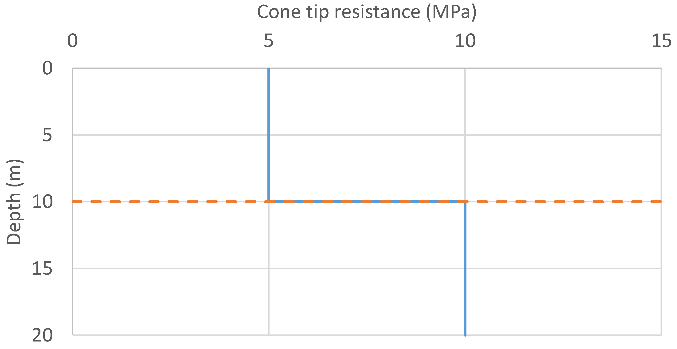
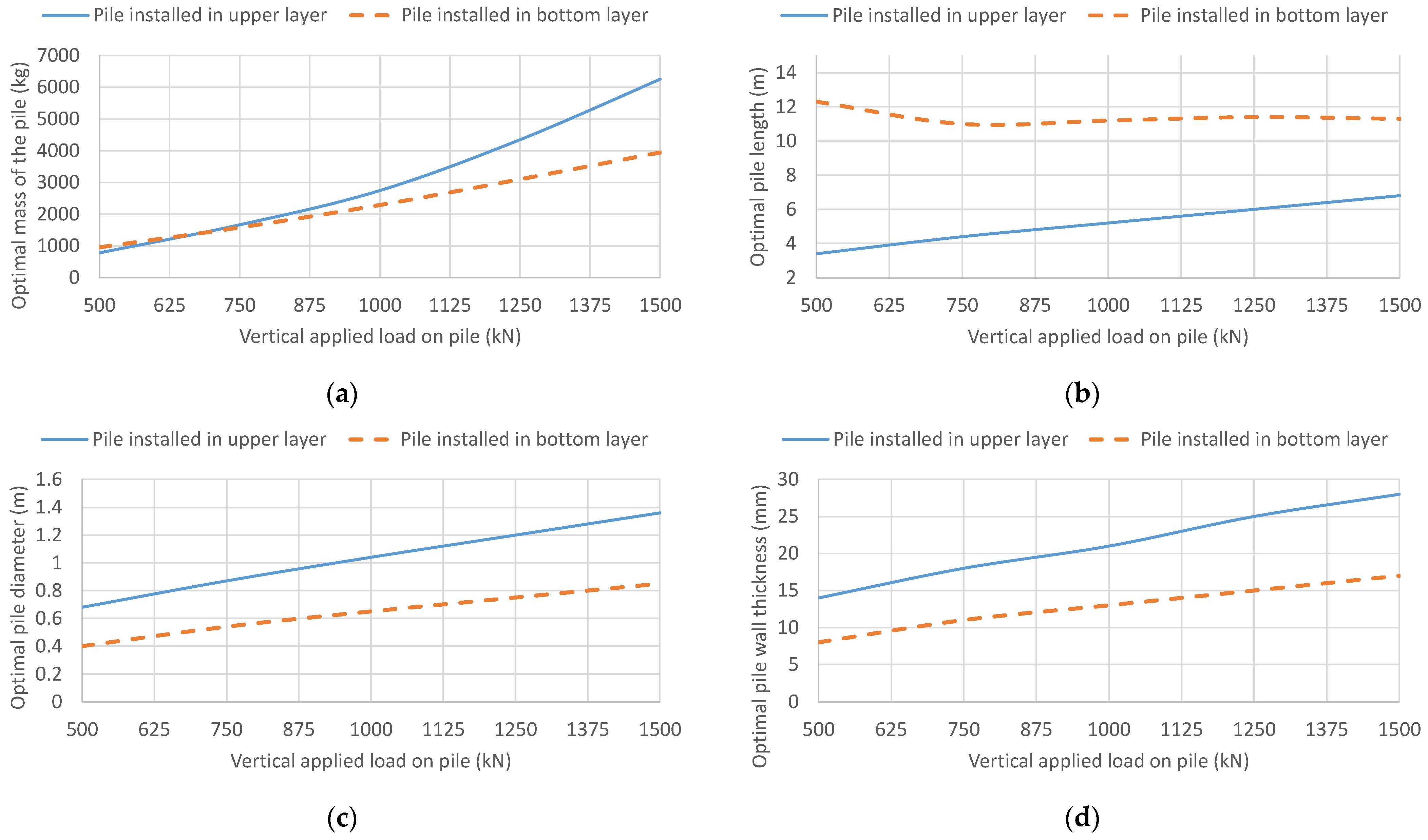
5. Case Study II: Layered Soil Profile

The aim of this case study is to present the optimal designs of open-end piles in a two-layer soil profile. The upper layer has half the cone tip resistance qc of the lower layer (see Figure 6). The thickness of the upper layer is 10 m. Although the length of the pile must be increased so that it can be supported by the lower layer, it is more economical to place the pile base in the bottom layer if the load is greater than 675 kN (see Figure 7a). The pile installed in the upper layer requires a larger pile diameter, a greater wall thickness and a shorter pile length to carry the same load as a pile with the pile base located in bottom layer (see Figure 7b–d). The decision of where to place the pile end base depends on the resistance of the cone tip and the thickness of each layer. To determine in which layer we want to place the pile base, we need to perform an optimization for the given design data.
Table 3 presents the ratios of pile dimensions for piles installed in different soil layers (upper or bottom layer).
The ratio of diameter to wall thickness shows that the piles installed in the bottom layer are significantly longer in relation to their diameter than those in the upper layer. A similarly optimal ratio (approx. 50) between wall thickness and diameter was determined for the base of the piles in the upper and bottom layers, indicating a uniform wall thickness in relation to diameter.

6. Conclusions

This article deals with the mass optimization of an open-end pile. A real-coded genetic algorithm was used to solve the integer design problems. From this, an integer optimization model OPEN-Pile was constructed. The model consists of an objective function for the pile mass that is subject to a number of geotechnical and design constraints that are consistent with current codes of practice and recommendations. In addition, the cone tip resistance results from a CPT measurement are taken into account directly in the design of steel pipe piles. The average values of cone sleeve resistance and cone tip resistance were calculated using integral functions. This approach increases computational complexity and makes the model more intricate, thereby rendering calculations more challenging.
Cone penetration testing (CPT) is less reliable in dense or gravelly soils and those containing large cobbles or boulders due to the increased resistance and potential damage to the equipment. It is most effective in fine-grained, uniform soils, while it is less accurate in heterogeneous soils. CPT provides limited lateral coverage, so multiple tests are required for a comprehensive spatial analysis, which can be costly and time-consuming. A high water table can affect the accuracy of measurements, particularly of pore pressure and soil resistance. In addition, the depth of the CPT is limited by the capacity of the equipment and the subsurface conditions, so alternative methods are required for deeper investigations.
The computer program MATLAB (R2021a) and the real-coded genetic algorithm (RCGA) were applied. The optimal design of open-end pile masses depends on several important design parameters, such as soil properties, soil profile, structural dimensions and the magnitude of the applied vertical load. Therefore, a sensitivity analysis of an open-ended pile was performed based on a series of optimizations carried out. The maximum economic load per pile was also determined by optimization. If the mass of a single pile increases exponentially due to the applied load, it is more economical to use two or more piles to carry the same vertical load. However, if the load is carried by several closely spaced piles, the influence of adjacent piles must be taken into account (reduced load-bearing capacity). In a layered soil profile, the decision of where to place the pile base depends on the resistance of the cone tip and the thickness of the individual layers. The examples illustrate the effectiveness of the proposed optimal design procedure. Based on the calculated results, the following design parameters are determined to be optimal in the case of Blessington sand:
-
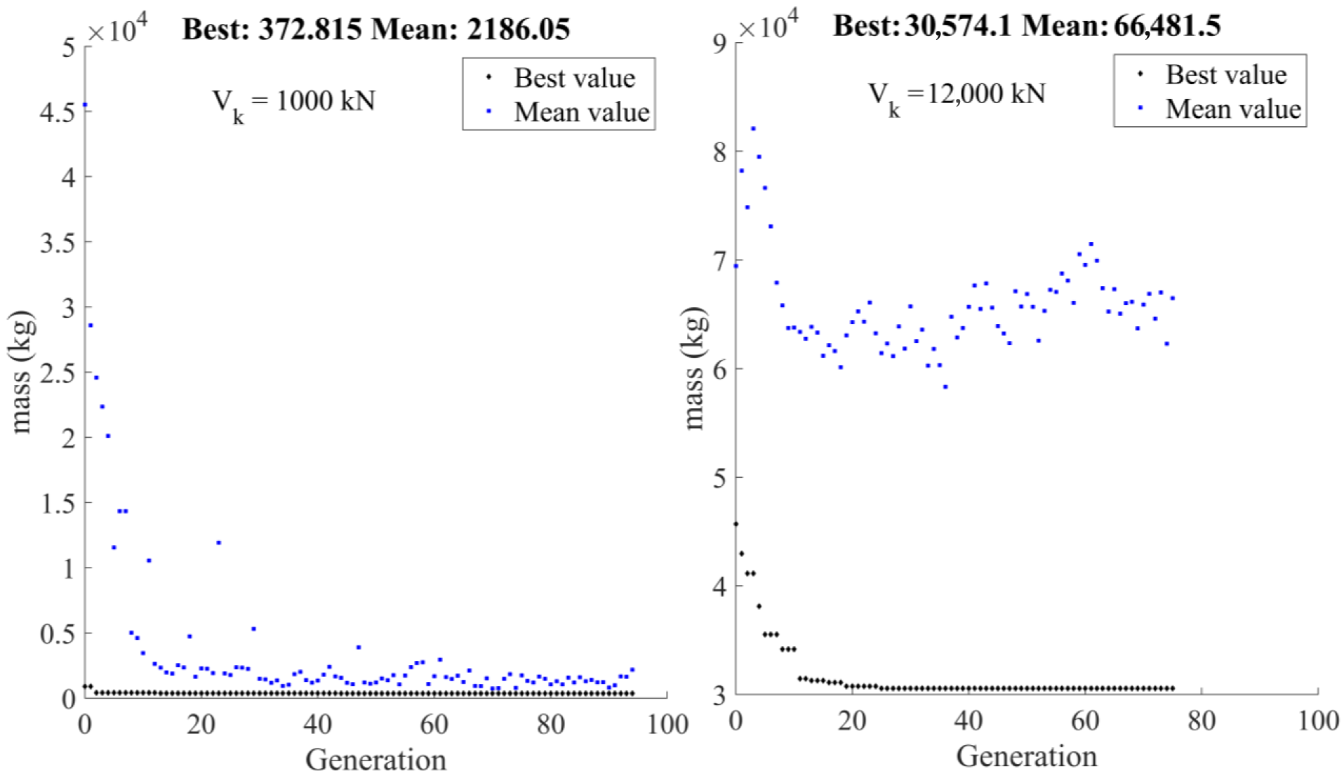
The linear increase in vertical load leads to an exponential increase in the mass of the pile. A 13-fold increase in the vertical load (from 1000 kN to 13,000 kN) increases the mass of the pile by a factor of 130.4 (from 373 kg to 49,348 kg).
-
The optimum ratios of pile length to diameter, diameter to wall thickness and length to wall thickness are 5, 50 and 250, respectively.
-
With a vertical load of 9000 kN, the optimum pile diameter reached its maximum value of 1.5 m.
The settlements of the pipe pile under the service load and the bending moments in the pile are most important or critical in some applications; therefore, additional boundary conditions should be added.Also, the impact of the pile dimensions on the pile installation in terms of CO2 emissions should be further investigated to further optimize the pipe piles. By integrating CPT data with geostatistical analyses, a more accurate map of the site will be obtained, leading to more reliable and efficient pile designs that account for both depth-related and spatial soil variability.

Funding

This research was funded by the Slovenian Research Agency (grant number P2-0268) and the GEOLAB project (grant number 101006512).

Institutional Review Board Statement

Not applicable.

Informed Consent Statement

Not applicable.

Data Availability Statement

The data presented in this study are available on request from the corresponding author.

Conflicts of Interest

The author declare no conflicts of interest.

Abbreviations

AbArea of the pile base
ArsEffective area ratio of the pile shaft
CbConstant for pipe piles
CO2Embodied CO2 emissions from pipe pile
DOutside diameter of pile
LLength of the pile
LuneffDepth below the ground level where any shaft friction is ignored
MASSMass of the pile
Nc,RdDesign axial force resistance
QbPile base capacity
QRdDesign bearing capacity of the pile
QsPile shaft capacity
QultTotal bearing capacity of the pile
VEdDesign vertical load
VGkVertical dead load
VQkVertical live load
aFirst best fit coefficient
bSecond best fit coefficient
cThird best fit coefficient
ciCO2Carbon index of steel
fs,aveAverage value of cone sleeve resistance
fyYield strength of steel
qc,aveAverage cone tip resistance over a distance 1.5D above and below the pile base
tThickness of the pile wall
zDepth
γGPartial safety factor for dead load
γM0 Material partial safety factor
γQPartial safety factor for live load
γRPartial safety factor for bearing capacity
γsUnit weight of the steel
δcv Soil–pile interface friction angle
εAdjustment by the factor
ρsDensity of the steel

References

  1. Kolk, H.J.; Baaijens, A.E.; Senders, M. Design criteria for pipe piles in silica sands. In Proceedings of the International Symposium on Frontiers in Offshore Geotechnics, Perth, Australia, 19–21 September 2005. [Google Scholar]
  2. Jardine, F.M.; Chow, F.C.; Overy, R.F.; Standing, J.R. ICP Design Methods for Driven Piles in Sands and Clays; Thomas Telford Ltd.: London, UK, 2005; ISBN 978-0-7277-3272-9. [Google Scholar]
  3. Xu, X.; Lehane, B.M. Evaluation of end-bearing capacity of closed-ended pile in sand from cone penetration data. In Proceedings of the International Symposium on Frontiers in Offshore Geotechnics ISFOG 2005, Perth, Australia, 19–21 September 2005. [Google Scholar]
  4. Xu, X.; Schneider, J.A.; Lehane, B.M. Cone penetration test (CPT) methods for end-bearing assessment of open- and closed-ended driven piles in siliceous sand. Can. Geotech. J. 2008, 45, 1130–1141. [Google Scholar] [CrossRef]
  5. Gavin, K.G.; Lehane, B.M. The shaft capacity of pipe piles in sand. Can. Geotech. J. 2003, 40, 36–45. [Google Scholar] [CrossRef]
  6. Igoe, D.; Doherty, P.; Gavin, K. The Development and Testing of an Instrumented Open-Ended Model Pile. Geotech. Test. J. 2010, 33, 72–82. [Google Scholar] [CrossRef]
  7. Gavin, K.G.; O’Kelly, B.C. Effect of Friction Fatigue on Pile Capacity in Dense Sand. J. Geotech. Geoenviron. Eng. 2007, 133, 63–71. [Google Scholar] [CrossRef]
  8. Kodsy, A.; Iskander, M. Insights into Plugging of Pipe Piles Based on Pile Dimensions. Appl. Sci. 2022, 12, 2711. [Google Scholar] [CrossRef]
  9. Lehane, B.M.; Schneider, J.; Xu, X. The UWA-05 method for prediction of axial capacity of driven piles in sand. In Proceedings of the International Symposium on Frontiers in Offshore Geotechnics (IS-FOG 2005), Perth, Australia, 19–21 September 2005. [Google Scholar]
  10. Bui-Ngoc, T.; Nguyen, T.; Nguyen-Quang, M.-T.; Shiau, J. Predicting load–displacement of driven PHC pipe piles using stacking ensemble with Pareto optimization. Eng. Struct. 2024, 316, 118574. [Google Scholar] [CrossRef]
  11. Wang, Z.; Zhou, J.; Du, K.; Khandelwal, M. Enhanced multi-task learning models for pile drivability prediction: Leveraging metaheuristic algorithms and statistical evaluation. Transp. Geotech. 2024, 47, 101288. [Google Scholar] [CrossRef]
  12. Xi, L.; Jin, L.; Ji, Y.; Liu, P.; Wei, J. Prediction of Ultimate Bearing Capacity of Soil–Cement Mixed Pile Composite Foundation Using SA-IRMO-BPNN Model. Mathematics 2024, 12, 1701. [Google Scholar] [CrossRef]
  13. Fattahi, H.; Ghaedi, H.; Malekmahmoodi, F.; Armaghani, D.J. Optimizing pile bearing capacity prediction: Insights from dynamic testing and smart algorithms in geotechnical engineering. Measurement 2024, 230, 114563. [Google Scholar] [CrossRef]
  14. Leung, Y.F.; Klar, A.; Soga, K. Theoretical Study on Pile Length Optimization of Pile Groups and Piled Rafts. J. Geotech. Geoenviron. Eng. 2010, 136, 319–330. [Google Scholar] [CrossRef]
  15. Xue, J.; Gavin, K.; Murphy, G.; Doherty, P.; Igoe, D. Optimization Technique to Determine the p-y Curves of Laterally Loaded Stiff Piles in Dense Sand. Geotech. Test. J. 2016, 39, 842–854. [Google Scholar] [CrossRef]
  16. Jelušič, P.; Žlender, B. Optimal design of piled embankments with basal reinforcement. Geosynth. Int. 2018, 25, 150–163. [Google Scholar] [CrossRef]
  17. Jelušič, P.; Žlender, B. Determining optimal designs for conventional and geothermal energy piles. Renew. Energy 2020, 147, 2633–2642. [Google Scholar] [CrossRef]
  18. Charles, J.A.; Gourvenec, S.M.; Vardy, M.E. Coupling site wide CPT profiles and genetic algorithms for whole-site offshore windfarm layout optimization. In Cone Penetration Testing 2022; CRC Press: London, UK, 2022; pp. 870–875. [Google Scholar]
  19. Abushama, K.; Hawkins, W.; Pelecanos, L.; Ibell, T. Minimising the embodied carbon of reinforced concrete piles using a multi-level modelling tool with a case study. Structures 2023, 58, 105476. [Google Scholar] [CrossRef]
  20. Abushama, K.; Hawkins, W.; Pelecanos, L.; Ibell, T. Embodied carbon optimisation of concrete pile foundations and comparison of the performance of different pile geometries. Eng. Struct. 2024, 310, 118109. [Google Scholar] [CrossRef]
  21. Lyu, F.; Shao, H.; Zhang, W. Comparative analysis about carbon emission of precast pile and cast-in-situ pile. Energy Rep. 2022, 8, 514–525. [Google Scholar] [CrossRef]
  22. Pop, I.; Wan-Wendner, L.; Vits, W. Optimized Structural Design of Concrete Pile Plug in Steel Pipe Piles. ACI Struct. J. 2022, 119, 153–163. [Google Scholar] [CrossRef]
  23. Inazumi, S.; Shakya, S. A Comprehensive Review of Sustainable Assessment and Innovation in Jet Grouting Technologies. Sustainability 2024, 16, 4113. [Google Scholar] [CrossRef]
  24. Lee, J.-H.; Tran, N.X.; Kim, S.-R. Development and field application of GFRP suction pile. Ocean Eng. 2019, 173, 308–318. [Google Scholar] [CrossRef]
  25. Almallah, A.; El Naggar, H.; Sadeghian, P. Axial Behavior of Innovative Sand-Coated GFRP Piles in Cohesionless Soil. Int. J. Geomech. 2020, 20, 04020179. [Google Scholar] [CrossRef]
  26. Lowry, K.; Rayhani, M.T. Factors affecting axial and lateral load transfer of hollow fibre-reinforced polymer piles in soft clay. Int. J. Geotech. Eng. 2023, 17, 644–653. [Google Scholar] [CrossRef]
  27. Farhangi, V.; Karakouzian, M. Effect of Fiber Reinforced Polymer Tubes Filled with Recycled Materials and Concrete on Structural Capacity of Pile Foundations. Appl. Sci. 2020, 10, 1554. [Google Scholar] [CrossRef]
  28. Rens, K.L.; Liu, R.; Foltz, S.D. Sustainable Approach for Optimal Steel Sheet Pile Structure Assessment, Maintenance, and Rehabilitation. J. Perform. Constr. Facil. 2013, 27, 181–190. [Google Scholar] [CrossRef]
  29. Das, B.M. Principles of Foundation Engineering, 7th ed.; CL-Engineering: Chonburi, Thailand, 2010; ISBN 0495668109. [Google Scholar]
  30. Suzuki, Y.; Akash, Y.; Sawaizumi, S.; Hirakaw, T.; Kameyama, A.; Taenaka, S. Nippon Steel Corporation’ s Construction Products and Technologies for Carbon Neutral Buildings and Infrastructures; Nippon Steel Technical Report; Nippon Steel Corporation: Tokyo, Japan, 2024; pp. 10–16. [Google Scholar]
  31. The Model of the Eco-costs/Value Ratio (EVR). Available online: www.ecocostsvalue.com/eco-costs/eco-costs-emissions/ (accessed on 7 June 2024).
  32. Poulos, H.G. Pile behaviour—Theory and application. Géotechnique 1989, 39, 365–415. [Google Scholar] [CrossRef]
  33. Quevedo-Reina, R.; Álamo, G.M.; François, S.; Lombaert, G.; Aznárez, J.J. Importance of the soil–structure interaction in the optimisation of the jacket designs of offshore wind turbines. Ocean Eng. 2024, 303, 117802. [Google Scholar] [CrossRef]
  34. Zhang, Y.; Deng, Z.; Chen, P.; Luo, H.; Zhang, R.; Yu, C.; Zhan, C. Experimental and Numerical Analysis of Pile–Rock Interaction Characteristics of Steel Pipe Piles Penetrating into Coral Reef Limestone. Sustainability 2022, 14, 13761. [Google Scholar] [CrossRef]
  35. Zhang, X.; Li, J. Study on the structure parameters and design method optimization of blade-type screw steel pipe pile. Heliyon 2024, 10, e35046. [Google Scholar] [CrossRef]
  36. Forcellini, D. Analytical fragility curves of pile foundations with soil-structure interaction (SSI). Geosciences 2021, 11, 66. [Google Scholar] [CrossRef]
  37. Mina, D.; Forcellini, D.; Karampour, H. Analytical fragility curves for assessment of the seismic vulnerability of HP/HT unburied subsea pipelines. Soil Dyn. Earthq. Eng. 2020, 137, 106308. [Google Scholar] [CrossRef]
  38. Tomlinson, M.; Woodward, J. Pile Design and Construction Practice; CRC Press: Boca Raton, FL, USA, 2007; ISBN 9780429224461. [Google Scholar]
  39. Bowles, J.E. Foundation Analysis and Design; Civil Engineering Series; McGraw-Hill: New York, NY, USA, 1997; ISBN 9780071188449. [Google Scholar]
  40. Abouzaid, A.; El Naggar, M.H.; Drbe, O. Comprehensive Evaluation of Lateral Performance of Innovative Post in Sand. Appl. Sci. 2024, 14, 2442. [Google Scholar] [CrossRef]
  41. Bao, H.; Peng, J.; Cheng, Z.; Hong, J.; Gao, Y. Experimental Study on Inner Interface Mechanical Properties of the ESDCM Pile with Steel Core. Buildings 2023, 13, 486. [Google Scholar] [CrossRef]
  42. Aleem, M.; Bhattacharya, S.; Cui, L.; Amani, S.; Salem, A.R.; Jalbi, S. Load utilisation (LU) ratio of monopiles supporting offshore wind turbines: Formulation and examples from European Wind Farms. Ocean Eng. 2022, 248, 110798. [Google Scholar] [CrossRef]
  43. Deep, K.; Singh, K.P.; Kansal, M.L.; Mohan, C. A real coded genetic algorithm for solving integer and mixed integer optimization problems. Appl. Math. Comput. 2009, 212, 505–518. [Google Scholar] [CrossRef]
  44. Venkataraman, P. Applied Optimization with Matlab Programming; Wiley: Hoboken, NJ, USA, 2009; ISBN 047008488X. [Google Scholar]
  45. The MathWorks, Inc., R. How the Genetic Algorithm Works. 2021. Available online: https://se.mathworks.com/help/gads/how-the-genetic-algorithmworks.html (accessed on 8 June 2024).
  46. Lehane, B.M.; Randolph, M.F. Evaluation of a Minimum Base Resistance for Driven Pipe Piles in Siliceous Sand. J. Geotech. Geoenviron Eng. 2002, 128, 198–205. [Google Scholar] [CrossRef]
  47. EN 1993-1-1 Eurocode 3; Design of Steel Structures. General Rules and Rules for Buildings. CEN: Brussels, Belgium, 2005.
  48. Deb, K. An efficient constraint handling method for genetic algorithms. Comput. Methods Appl. Mech. Eng. 2000, 186, 311–338. [Google Scholar] [CrossRef]
  49. De Nicola, A.; Randolph, M.F. The plugging behaviour of driven and jacked piles in sand. Géotechnique 1997, 47, 841–856. [Google Scholar] [CrossRef]
Figure 1. Optimization of pipe pile based on CPT results.
Sustainability 16 06880 g001
Figure 2. Flowchart for obtaining an optimal design for an open-end pile.
Sustainability 16 06880 g002
Figure 3. The results of the cone tip resistance from a CPT together with the approximation function.
Sustainability 16 06880 g003
Figure 4. Best score mass and mean score mass versus optimization progress for an applied load of 1000 kN and 12,000 kN.
Sustainability 16 06880 g004
Figure 5. The optimal mass, diameter and thickness of the open-end pile for different applied vertical loads.
Sustainability 16 06880 g005
Figure 6. The cone tip resistance of a two-layer soil.
Sustainability 16 06880 g006
Figure 7. The optimal mass (a), length (b), diameter (c) and thickness (d) of the open-end pile for a different applied vertical load and locations of the pile base.
Sustainability 16 06880 g007
Table 1. Discrete alternatives of the pile dimensions.
VariableMinimumIncrement (Step) MaximumNumber of Discrete Alternatives
D (m)0.300.11.50121
L (m)2.00.150.0481
t (m)0.0050.0010.05046
Table 2. Optimal design of an open-end pile for different applied loads.
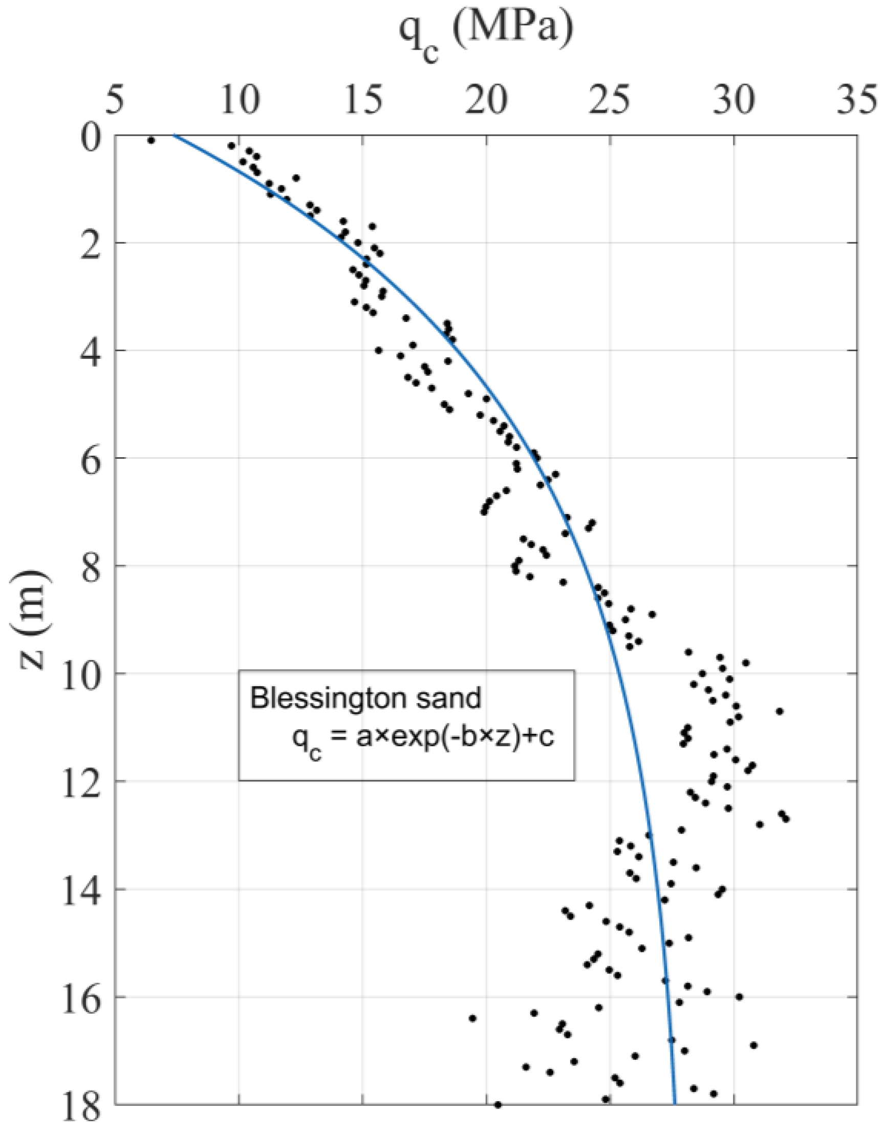
Blessington Sand (a = −28.83, b = 0.1999, c = 28.18)
Load VGk (kN)100020003000400050007000900011,00012,00013,000
D (m)0.520.730.881.021.151.371.51.51.51.5
L (m)2.73.74.55.25.86.910.111.917.127.6
t (mm)11151821232830505050
MASS (kg)373979172226903708639410,98421,27730,57449,348
CO2 (kgCO2)324.3851.41498.12340.63225.75562.99556.518,510.726,599.542,932.5
Utilization rate of geotechnical and structural conditions
VEd/QRd (%)100981009999100100100100100
L/Lmin (%)96999898999974634427
(L/D)/50 (%)10101010101013162337
(D/t)/50 (%)9597989710098100606060
VEd/Ncrd (%)24252626262528212325
Ratios of pipe pile dimensions
L/D5.25.15.15.15.05.06.77.911.418.4
D/t47.348.748.948.650.048.950.030.030.030.0
L/t245.5246.7250.0247.6252.2246.4336.7238.0342.0552.0
Table 3. Optimum design ratios of pipe piles for pile base installed in the upper and lower layers.
Pile Base Installed in Upper Layer
Load VGk (kN)500750100012501500
L/D5.05.15.05.05.0
D/t48.648.349.548.048.6
L/t243244248240243
Pile Base Installed in Bottom Layer
L/D30.820.417.215.213.3
D/t50.049.150.050.050.0
L/t15381000862760665
Disclaimer/Publisher’s Note: The statements, opinions and data contained in all publications are solely those of the individual author(s) and contributor(s) and not of MDPI and/or the editor(s). MDPI and/or the editor(s) disclaim responsibility for any injury to people or property resulting from any ideas, methods, instructions or products referred to in the content.

