Abstract
The hybrid photovoltaic (PV) with energy storage system (ESS) has become a highly preferred solution to replace traditional fossil-fuel sources, support weak grids, and mitigate the effects of fluctuated PV power. The control of hybrid PV-power systems as generation-storage and their injected active/reactive power for the grid side present critical challenges in optimizing their performance. Therefore, this paper introduces hybrid PV-battery parallel inverters employing a finite control set model predictive control (FCSMPC) method. The proposed FCSMPC-based controller and inverter system achieves multiple functionalities, including maximum power extraction from PV, proper charging/discharging commands for ESS, support for weak grid conditions, support during low-voltage ride-through (LVRT) by increasing reactive power injection to counteract the drop in grid voltage, and economic management based on feed-in-tariff (FiT). The controller significantly improves the performance of the PV-battery system under faulty LVRT conditions and unbalanced grid voltages, satisfying grid code requirements while continuously supplying the microgrid’s delicate local load. A real-time simulation hardware-in-the-loop (HiL) setup, utilizing the OPAL-RT platform, is employed to implement the proposed hybrid PV–ESS with its controller. The results affirm the superior ability of FCSMPC in weak-grid conditions and its capability to achieve multiple objectives simultaneously.
1. Introduction
1.1. Overview
The vast interest and governmental plans for the extensive installation of renewable energy systems (RESs) represent an effective and sustainable solution for the existing energy crisis [1]. Solar PV generation systems comprise the majority of recent RES installations, and share higher worldwide capacity than wind generation. Increased experience, continuous cost reduction, and technological development have contributed to increasing the installed PV capacity. Moreover, PV systems do not include mechanical parts, have a long useful lifetime, and are available everywhere [2].
However, output PV power relies on environmental conditions, such as solar irradiance levels and subjected ambient temperature. It also suffers from the unavailability of the sun during nighttime and shading effects [3,4]. These problems can be effectively solved by integrating energy storage systems (ESSs) [5]. Several ESSs with a wide range of applications have been applied in the literature, and were shown to have highly improved system performance [6]. Additionally, the ESSs can help support electrical grids during different types of faults/abnormal conditions and normal operating conditions [7].
The unpredictable behavior of PV energy results in inconsistent power contributions to the utility grid. From the perspective of power grid operation, this attribute is seen as an unfavorable aspect in terms of power quality, stability, and supply reliability [8,9]. It also imposes difficulties for utility grids to manage the balance of power in their distribution networks. Additionally, the variations in extracted power from PV panels with solar irradiance levels and temperature continuously need to find the maximum power point (MPP) location. Hence, the literature has widely regarded the maximum power point tracking (MPPT) control methods. Among MPPT methods, the perturbation and observation (P&O) MPPT method has been widely applied due to its simplicity, effectiveness, and easy implementation [10,11].
1.2. Literature Review
In weak grid conditions, grid voltages are susceptible to disruptions from nonlinear loads, leading to unbalanced or distorted voltages and increasing the probability of low voltage sags and swells [12]. This can cause the PV system to trip due to over-current protection, potentially triggering a cascading effect that could lead to a complete blackout. To address these issues, a hybrid PV–ESS system with a robust control technique is proposed in [13,14] to enhance Low Voltage Ride Through (LVRT) capabilities, keeping the PV system connected during faults and ensuring overall grid stability.
The structures of PV systems and their control are based on employing power electronic conversion systems. Power electronics converters enable high-quality voltage/current injection, MPPT with fewer sensors, and integration with various RESs and ESSs. Power inverters using multilevel outputs, like the three-level neutral point clamped (3L-NPC) inverters, are widely used for PV and ESS integration with utility grids [15]. The 3L-NPC inverter, with its two series DC-link capacitors, supports power coupling between DC and AC sides, and offers cost, weight, size, and component savings by serving as a single-stage converter for PV and battery energy storage systems (BESS) [16,17]. Therefore, the PV and BESS sides are grid-integrated within this work by employing 3L-NPC inverters.
On the other hand, power quality is crucial in evaluating control methods for inverter systems, which can be affected by factors like nonlinear loads and power electronics devices [18,19]. Various algorithms have been proposed to improve control techniques for PV–ESSs, with some focusing on enhancements in existing control techniques, while others rely on external devices [20]. To clarify, static voltage compensators (SVC) and static synchronous compensators (STATCOM) are used to boost Fault Ride Through (FRT) capability by providing reactive power and stabilizing voltage in PV systems [21]. However, these hardware solutions increase system cost and complexity [22,23].
The study in [24] developed a method that coordinates STATCOM with a PV system to mitigate grid disturbances and enhance LVRT capability. While STATCOMs have limited energy storage, they can supply reactive currents during grid outages. The photovoltaic array adjusts its power output based on grid voltage dips to maintain balance. Though this system responds faster and with fewer disruptions than SVC, it has drawbacks like requiring multiple switches and a coupling transformer, and being unable to supply active power.
Some researchers have enhanced LVRT capabilities by using a current limiter [25]. For instance, Ref. [26] describes a system that regulates the PV array’s output power and injects reactive power by setting the desired positive sequence current, ensuring precise control and system stability. Another approach in [27] uses a hardware-based hysteresis current control technique to limit the output currents of three-phase, three-wire inverters.
A current limiting control technique for multi-module parallel UPS inverters has been introduced in [28], where the secondary module’s current command is generated based on the preceding module, with amplitude constrained by instantaneous saturation, leading to distorted output currents. This method requires costly and complex control systems with high-bandwidth loops and communication delay compensation. Additionally, Ref. [29] utilized a bridge-type fault current limiter (BFCL) system to improve LVRT capability in a grid-connected microgrid, coordinating BFCL and Voltage Source Converters (VSCs) to maintain voltage levels during grid voltage sags.
Numerous studies have focused on improving FRT capabilities by integrating BESSs and superconducting magnetic energy storage systems (SMESs) [30,31,32]. This integration protects the inverter and DC-link from voltage surges during grid faults, though it comes with high maintenance needs and initial costs. While these systems can reduce AC current peaks, store excess energy, and inject reactive current, they may also cause fluctuations in DC parameters before and after a fault.
Transitioning to the second trend towards enhancing FRT capability, a significant global investment is being directed towards improving electrical power infrastructure. Researchers have proposed various FRT control strategies for voltage sag optimization and fault current management [25]. Classical control methods based on single-stage PV systems could be more efficient/suitable for low grid voltages, leading to potential PV system disconnection during large voltage drops [33]. In [34,35], a flexible DC-link voltage control for two-stage PV systems optimizes MPPT under normal and abnormal conditions, and can be adapted for single-stage systems. However, it may require power compromises in certain scenarios.
A distributed-incremental adaptive filtering (DIAF) method for PV-BESSs has been proposed in [36] to improve performance. However, it does not fully address load variations. In [37], an alternative approach is presented, using an adaptive learning-based back-propagation (AL-BP) controller, adjusting grid currents based on power balance, but lacking support during overvoltage, undervoltage, and grid absence [37].
MPC is increasingly used in grid-connected systems due to its ability to handle multiple objectives simultaneously, removing the need for cascaded linear/nonlinear controllers [38,39,40]. MPC offers high control bandwidth and speed, especially in grid-connected VSCs [41]. It is also applied in master–follower microgrids [42], sensorless MPC for LC-filtered VSCs [43], and hierarchical control for smart grids [44]. However, further development is needed to integrate additional functionalities for AC microgrids.
A resilient framework for controlling PV-BESSs has been presented in [45] to alleviate several issues, such as the intermittent injected PV power being charged and/or discharged based on load conditions and PV-generated power. The inclusion of feed-in-tariffs (FiTs) has been provided in [46,47] to balance residential demand-supply profiles and enhance the economic benefits of PV systems by improving flexibility and aligning with grid power updates.
Table 1 provides an overview and a concise comparison of FRT enhancement methods from existing literature, highlighting the unique objectives of this research compared to prior work.

Table 1.
Summarized overview of contributions of the current paper and existing work in the literature.
1.3. Problem Statement
The growing use of PV systems for sustainable energy introduces challenges for grid stability, particularly in weak grids. The fluctuations in power output due to environmental factors impact the grid power quality and reliability. Traditional FRT methods and hardware solutions can be complex and costly. Therefore, there is a need for an integrated control strategy to optimize hybrid PV-battery systems, ensuring stable operation in diverse grid conditions and maximizing economic benefits through FiT strategies.
This paper introduces the model predictive control strategy as an enabling control method for fulfilling the desired objectives to effectively control the hybrid PV-battery parallel inverters. This, in turn, is reflected as an improvement in the grid stability, better LVRT capabilities, and achieving multiple objectives. The control objectives include the maximum power extraction, efficient energy storage management, and economic optimization, especially under weak grid conditions and during grid disturbances.
1.4. Article Novelty
Based on the aforementioned challenges and existing efforts in the literature to enhance the FRT capability of a grid-connected PV system, this paper presents the following:
- A novel FCSMPC controller approach is presented in this paper for hybrid PV-battery parallel three-level NPC inverters. The proposed FCSMPC provides a flexible digital means for achieving multiple objectives simultaneously without the need for cascaded controllers.
- The FCSMPC-based algorithm facilitates the response to achieve multiple functionalities simultaneously, including MPPT control, ESS charging/discharging, weak grid support, LVRT control, and management of unbalanced grid voltage conditions. In contrast to classical controllers, FCSMPC eliminates the need for complex design procedures involving cascaded controllers.
- Additionally, economic management has been achieved in the system by employing the feed-in tariff (FiT) during the reference current generation.
- Real-time simulation HiL setup using the OPAL-RT platform is presented for implementing the proposed hybrid PV–ESS system with the FCSMPC algorithm.
In contrast to classical controllers, FCSMPC eliminates the need for complex design procedures involving cascaded controllers. Additionally, it offers unique advantages. It enables the control of both active and reactive current components during faults, addresses overcurrent issues during significant voltage dips and, importantly, prevents the sudden increase in the voltage on the DC-link. Additionally, economic management has been achieved in the system by employing the FiT during the reference current generation.
The remaining parts of the article are organized as follows: Section 2 presents the proposed System Model description, while Section 3 details the MPC control system and describes the FiT inclusion mechanism. Section 4 presents the findings from real-time simulation HiL. The paper is concluded in Section 5.
2. Model of the System
2.1. System Description
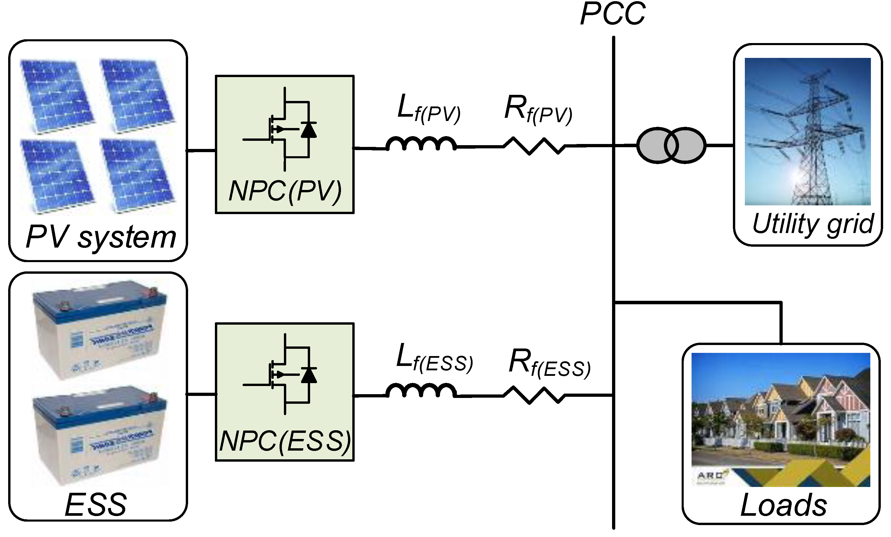
The schematic diagram of the proposed hybrid PV–ESS system is illustrated in Figure 1. As depicted in the figure, the PV system is connected to the point of standard coupling (PCC) by the use of an NPC inverter topology. The L-type filter (represented with filter inductance and resistance ) is employed for filtering the current harmonics. Another NPC inverter is utilized to integrate the ESS with PCC via the energy storage inverter filter (represented by and ). Additionally, various loads can be connected to the PCC and the grid connection. The control system of the hybrid PV–ESS is responsible for regulating the injected active and reactive power from both the PV side inverter and the ESS inverter, and the grid/load side interactions under the normal and the abnormal states. The design and management of the control method are critical elements for obtaining improved and optimized performance at the PCC of the grid system. This study assumes that the two controllers have direct communication signals and share the information and measurements. Moreover, this section presents generalized modeling and control due to the similarity of the PV inverter and ESS inverter using NPC topology. Although only two parallel inverters are considered in the proposed case study, the proposed approach is general, and can be extended to larger power grids. Moreover, it can be also integrated into other tertiary and secondary control levels.
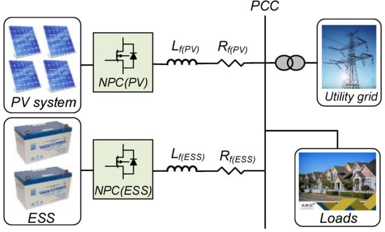
Figure 1.
The schematic diagram of the complete studied system.
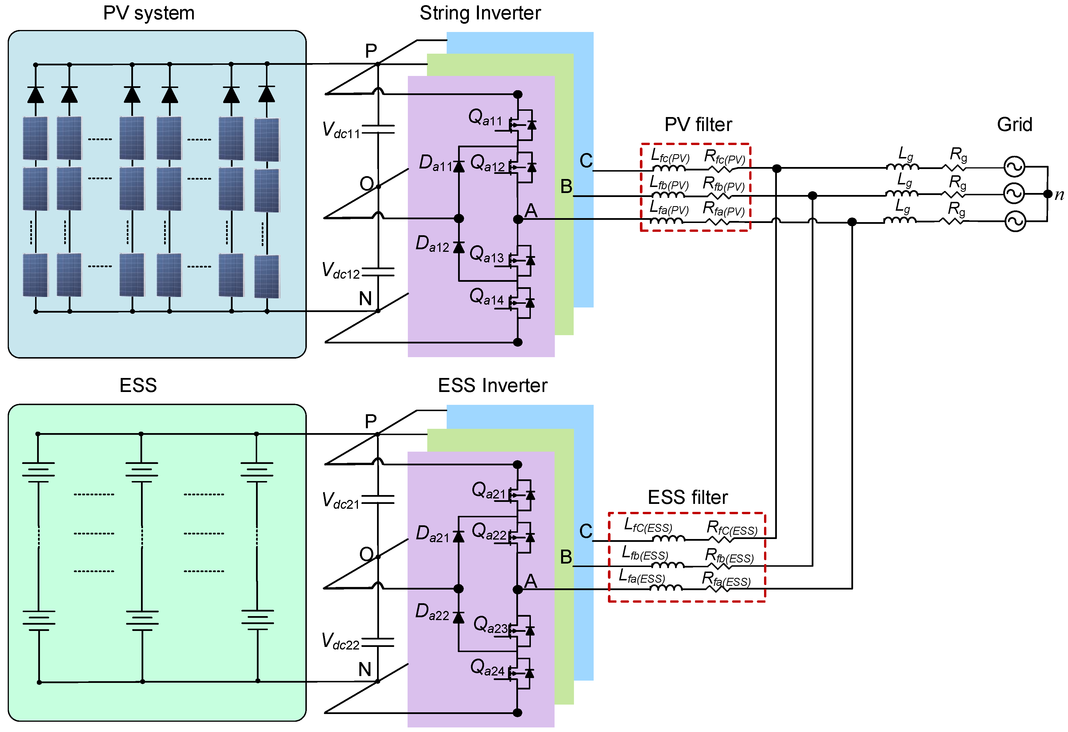
2.2. Three-Level NPC Operation
The topology of the three-level NPC inverter for PV and ESS integration is demonstrated in Figure 2. Due to the 3L-NPC inverter being employed in PV and ESS systems, a unified analysis has been made here, and it is suitable for both of them. The DC-link side voltage () is equally divided between the two series-connected DC-link capacitors ( and ). The control system is required to preserve balanced voltages over the series-connected DC-link capacitors ( = ), regardless of the output and/or the components’ symmetry. Each phase leg has three different switching states, namely the P, O, and N states. In each state, two switches are turned ON, and the other two are turned OFF. Table 2 summarizes the switching states and signals for each phase leg. The current path depends on the current direction and the applied states of the three switching states.
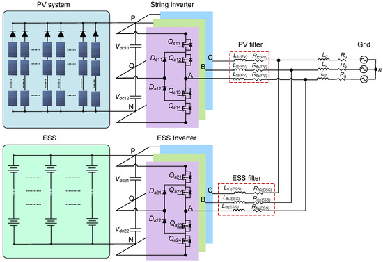
Figure 2.
The integration of PV and ESS with the PCC and grid side.
Table 2.
The outputted voltages with switching signal for three-level NPC phase leg.
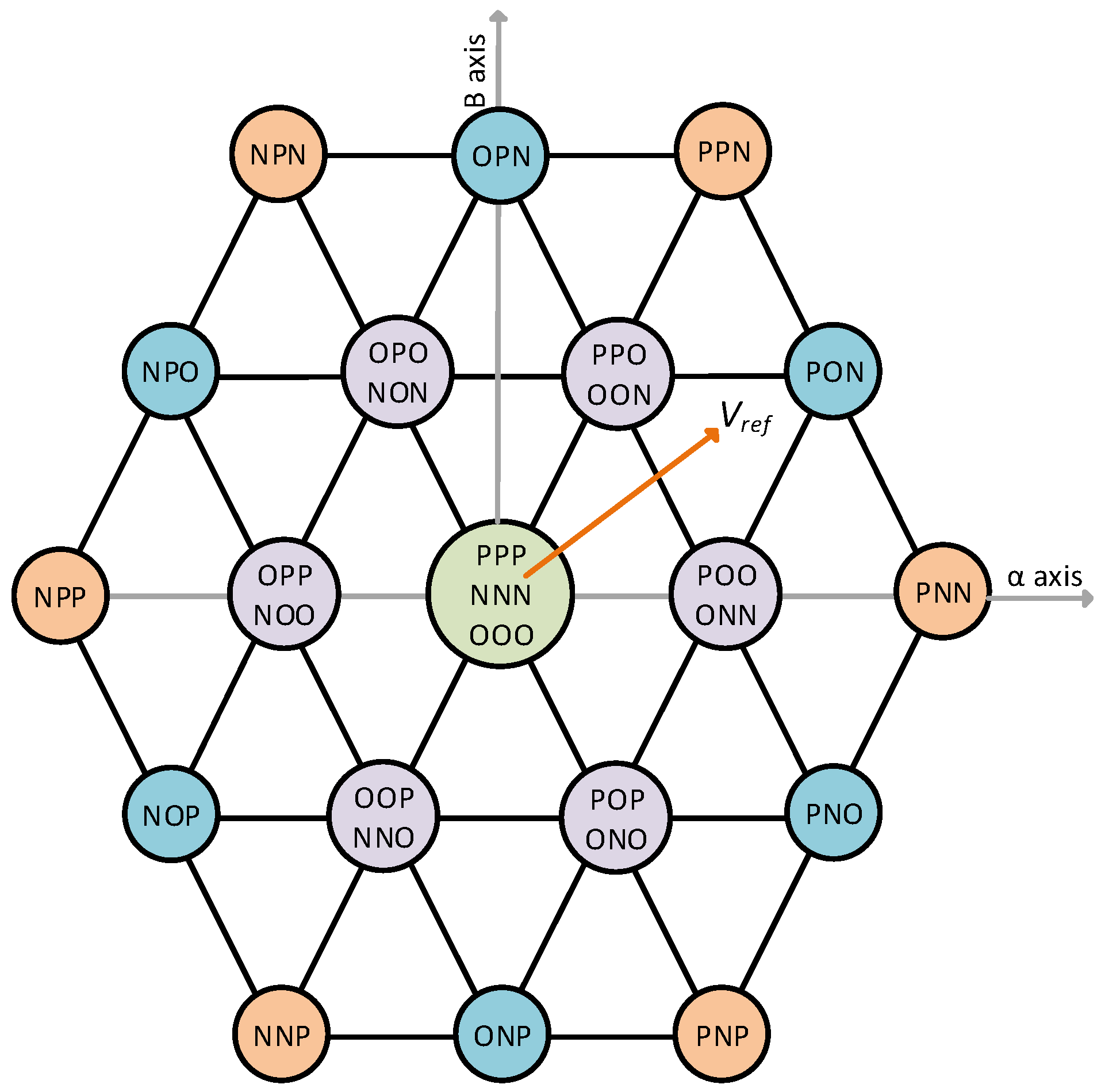
Each of the three legs can generate three different levels in the NPC topology output concerning the circuit’s neutral point (NP), node O. The three legs of phases A, B, and C together can generate number of switching vectors between the line–line of the inverter output. Figure 3 illustrates the space vector diagram of a 3L-NPC inverter, showcasing the presence of 27 distinct switching vectors. The vectors can be divided into (1) zero vectors, which include the PPP, OOO, and NNN vectors; (2) small positive vectors, which include the POO, PPO, OPO, OPP, OOP, and POP vectors; (3) small negative vectors, which include the NOO, NNO, ONO, ONN, OON, and NON-vectors; (4) medium vectors, which include the OPN, NPO, NOP, ONP, PNO, and PON vectors; and (5) large negative vectors, which include the PPN, NPN, NPP, NNP, PNP, and PNN vectors.
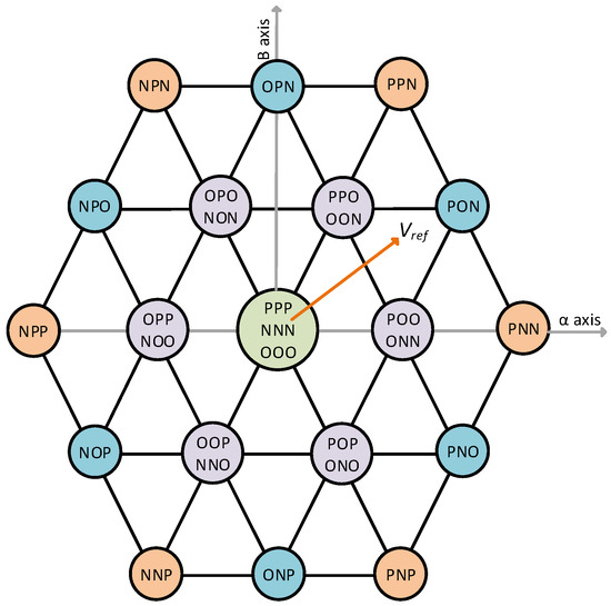
Figure 3.
The space vector diagram for three-level NPC topology.
Each of the different groups of vectors has distinct effects on the voltages of the DC-link capacitors. The presence of zero and large vectors does not exert any impact on the voltages of the capacitors. The small positive and negative vectors are controllable, and can increase/decrease the voltages based on the current direction. The medium vectors have effects on capacitor voltages; however, they are in uncontrollable states. Hence, by applying the proper vector, the output line–line voltage and capacitor voltages can be controlled. Therefore, the applied modulation and control algorithms have the flexibility to select the switching vector. Accordingly, the capacitor voltage balance and output voltage control can be achieved through developing proper control algorithms.
2.3. Mathematical Discrete Modeling of NPC Inverter
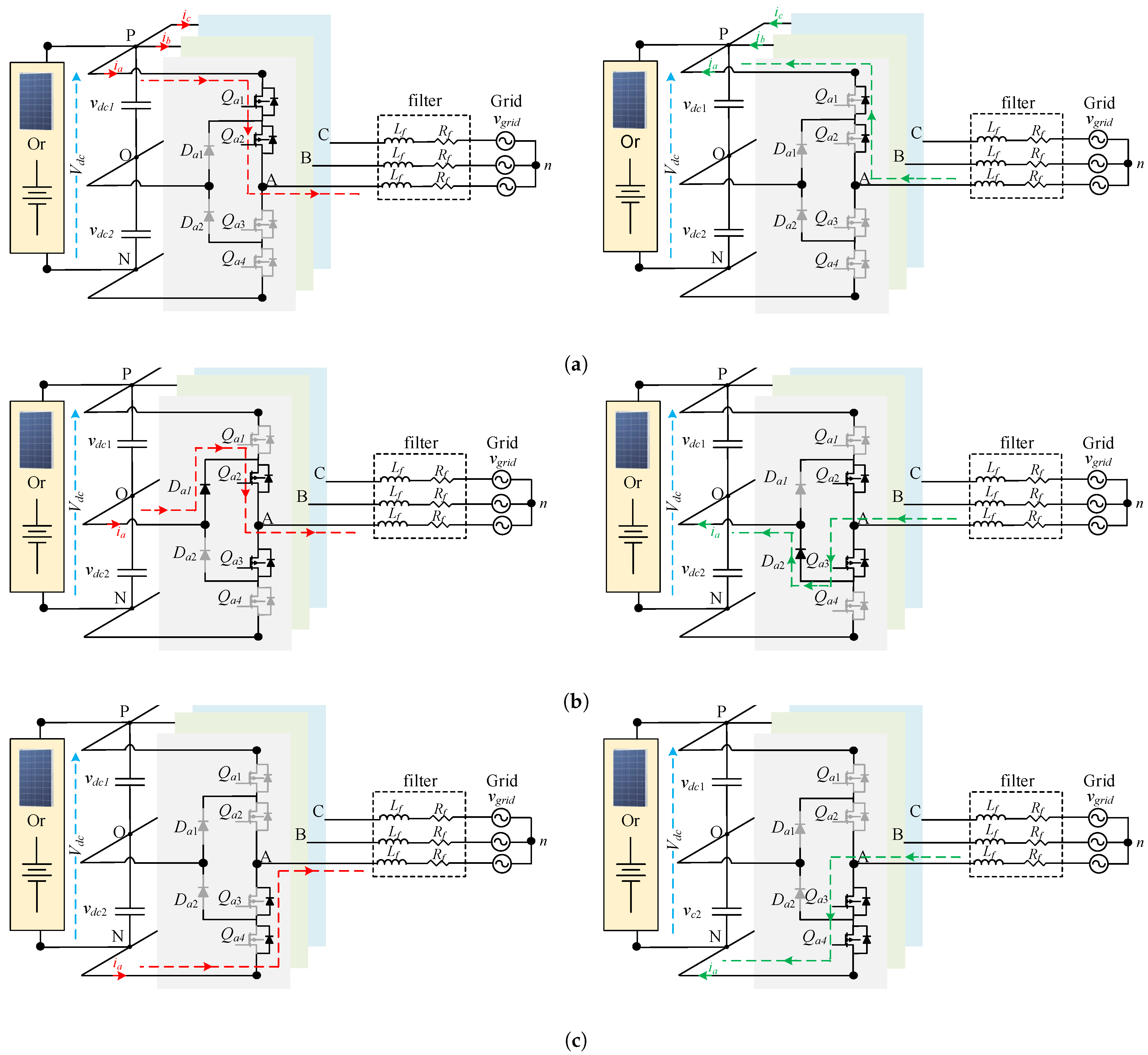
This section presents the discrete prediction model of a 3L-NPC grid-connected inverter. Subsequently, the discrete model of the MPC method for PV and ESS is detailed. The MPC’s cost function incorporates the voltages of the two capacitors in NPC inverters. This inclusion aims to enhance the system’s robustness and reduce steady-state errors. By integrating these capacitor voltages, the MPC leverages the benefits of existing control approaches. Figure 4 shows the current paths for positive/negative current directions of the states P, O, and N, respectively.
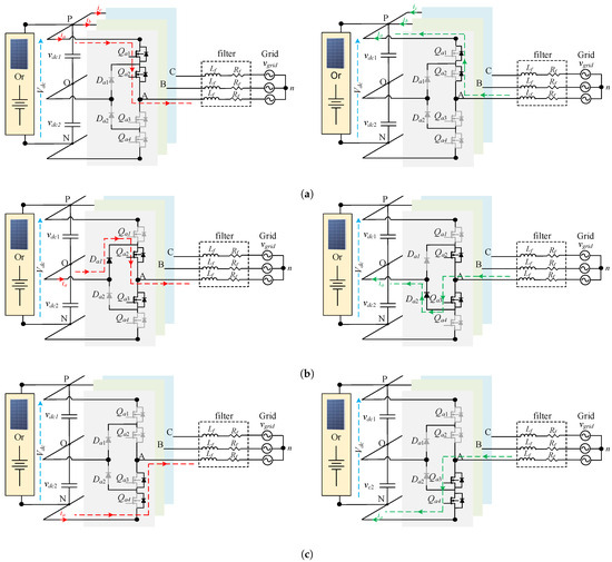
Figure 4.
Current paths () for three-level NPC leg. (a) Current path during P state (figure in left side is for positive current, and figure in right side is for negative current). (b) Current path during O state (figure on the left side is for positive current, and figure on the right side is for negative current). (c) Current path during N state (figure on the left side is for positive current, and figure on the right side is for negative current).
It is assumed that the filters are identical in the three phases ( = = = and also = = = ). Referring to Figure 4, the model based on dynamical continuous time representation of the inverter output currents can be expressed as:
where and denote filter inductance and resistance, respectively. Whereas , , and denote the injected three-phase currents by the inverter. , , and denote output three-phase inverter voltages from NPC legs concerning the neutral point O of input DC voltage. While , , and represent the grid side voltages from phase to neutral.
The voltage represents the common mode voltage (CMV) of the three-phase system. It is employed for the circuit representation of the system, and to apply Kirchhoff’s voltage law. However, the control of CMV is not performed in this paper, due to being out of its scope. It is calculated as:
For predicting the future of injected grid current by each inverter for the next sampling period, a derivative form for (1) is approximated as:
where represents the sampling period of the controller system. Afterward, (3) is used in (1), which represents the discretized form for forward Euler approximations. The complete discrete model for the predicted output current for inverter systems can be expressed as:
The inverter output voltages can be predicted using the switching signals as follows:
whereas CMV in (2) is predicted as follows:
For the capacitor voltages, continuous time representation of the voltages depends on their initial values and and currents passing through capacitors and in each instant as follows:
In the same way, the prediction of DC-link capacitor voltages and can be made for the future sampling period as follows:
For discrete-time prediction, the currents passing through capacitors depend on the applied switching state, the output current of each phase, and their directions. The capacitors’ currents can be predicted as follows:
3. Proposed Method
The overall proposed structure and detailed MPC controller are described in Figure 5. The main elements of the system controller are delineated as follows: Firstly, PV MPPT control is utilized to optimize the operation of the PVA by preserving their continuous operation at the MPP. The MPC Algorithm regulates three-phase currents in each inverter while maintaining voltage balance across the DC-link capacitors. Thirdly, a Control Mechanism at faulty conditions prevents grid overcurrent tripping in LVRT mode by injecting reactive power to mitigate voltage fluctuations and adhering to grid code-prescribed limits. Finally, the FiT mechanism adjusts PV and ESS operation based on FiT levels to optimize economic returns. This integrated approach ensures efficient power utilization, economic viability, and compliance with grid code requirements. All these elements are thoroughly explained and discussed in detail in the subsequent subsections.
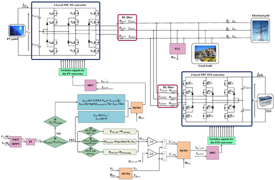
Figure 5.
The proposed control diagram for three-level NPC topology.
3.1. PV MPPT Control
In the initial phase, the current and voltage of the PV system are measured, and the MPPT control technique is employed. The perturb and observe (P&O) MPPT method is utilized to assure the optimal operation of the PVA, specifically with regard to the maximum voltage () and maximum current () at the MPP. The iterative control system continuously regulates the voltage and current of the PVA in response to the dynamic variations in irradiance and temperature.
First, to calculate the PVA’s reference current, it is necessary to establish the reference DC voltage. The output of the MPPT controller is fed as a reference voltage into a PI controller to regulate the DC-link voltage at this value. Then, the algorithm calculates the references for the active and reactive current used by the MPC controller based on the various operating points of the grid system.
3.2. MPC Algorithm
Each inverter has its own MPC algorithm, as described in Figure 5. So, the cost function of the implemented MPC approach incorporates the regulation of the output three-phase currents of each inverter to follow the reference current waveform accurately. Meanwhile, the references are estimated using the proposed algorithm to cope with the desired control functionalities and performance improvement.
Furthermore, the MPC algorithm is in charge of achieving the voltage equilibrium across the DC-link capacitors, which leads to ensuring identical capacitor voltages at half of the total DC voltage of the PV side voltage in the case of the PV inverter, or ESS voltage in the case of the ESS inverter. The representation of the MPC algorithm cost function to count for these objectives can be expressed as:
The symbol represents the weighting factor that determines the weight of the objective related to the balance of the DC-link between capacitors, whereas the variables , , and represent the inverter three-phase reference currents. Furthermore, , , and denote the projected three-phase currents for the 27 states of the inverter at time step , as detailed in Section 2. Similarly, and represent the predicted voltages of the capacitors for the inverter’s 27 states at time step . The design of the weighting factor represents a critical issue for MPC design [40,49]. The weighting factor calculation issue is still an open research area [50]. In the case of NPC control, compromising tracking of output AC current with capacitors’ voltage balance is needed. With larger values of , the capacitors’ voltage balance has higher control priority than AC current tracking. A common method to design weighting factors is represented in [51] as follows:
where stands for nominal/rated AC output current, and stands for DC-link capacitors reference voltages. In (14), the dimensions of is A/V.
3.3. Control Mechanism
As shown in Figure 5, during normal conditions, the function of the control system is to generate the reference values for the connected inverters. Regarding the active power of ESS , it is obtained from the difference between the combination of , which is the required power of the grid KW) at normal conditions, and the load power with the PV Power . Then, the calculated active powers are employed to generate the reference d-axis current. Then, the conversion is made from the -axis frame to the reference frame, fed into the MPC controller as reference values. After that, these currents are subjected to an MPC controller to generate the switches’ signals for both converters (PV, ESS), as described above.
Regarding faulty scenarios, the control system must rapidly identify the presence of the fault condition. It prevents over-current tripping when the grid voltage is below the minimal limit at LVRT faulty mode. Reactive power is introduced into the electrical grid to mitigate voltage fluctuations and support the system within the designated time frame outlined by the grid code. Therefore, grid currents are restricted from exceeding the prescribed threshold. So, the reference currents for the PV inverter side are calculated as follows:
where is the per-unit value of the grid voltage, is the rated current of the PV inverter, and is the maximum current of the PV inverter, which is equal to times of the rated current (), as in [48,52].
Consequently, the scope of the grid power () is subject to significant constraints. The implementation of overvoltage protection involves the utilization of flexible voltage regulation and the adjustment of the DC-link voltage () in response to an increase in the grid voltage (). This approach effectively prevents the system from operating inside the over-modulation region. Furthermore, the system has ceased providing electrical power to the grid, reducing the power () and the grid current () to a specified limit while maintaining grid synchronization without interruptions. In each situation, the reference current is obtained and subsequently applied to the proposed MPC algorithm to generate gating signals for power semiconductor switches of both ESS and PV inverter systems.
3.4. FiT Mechanism
To comply with the FiT policy, a FiT multiplication factor (FiT-MF) is utilized to achieve power adaptability while considering economic issues. Firstly, when the FiT can attain a high level, the PV system operates at its maximum power output and feeds electricity into the grid. In addition, a reduction in the BESSs’ charge due to discharging through the grid happens during this scenario. Hence, satisfactory financial return can be obtained due to injecting power into the grid at high FiT. Conversely, if the FiT takes a sufficiently low level in the designed method, the BESS is charged if its SoC is lower than 100%. Hence, the power injection into the grid is limited to the maximum power from the PV system. To clarify further, if the FiT value falls below zero, electrical power sourced from the grid supplies energy to the connected local loads while simultaneously recharging BESS. Thence, the BESS is charged at low FiT, and it can be utilized later during periods of high FiT rates. Accordingly, the PV-BESS’s economic operation will be improved using the proposed method.
4. Results and Discussion
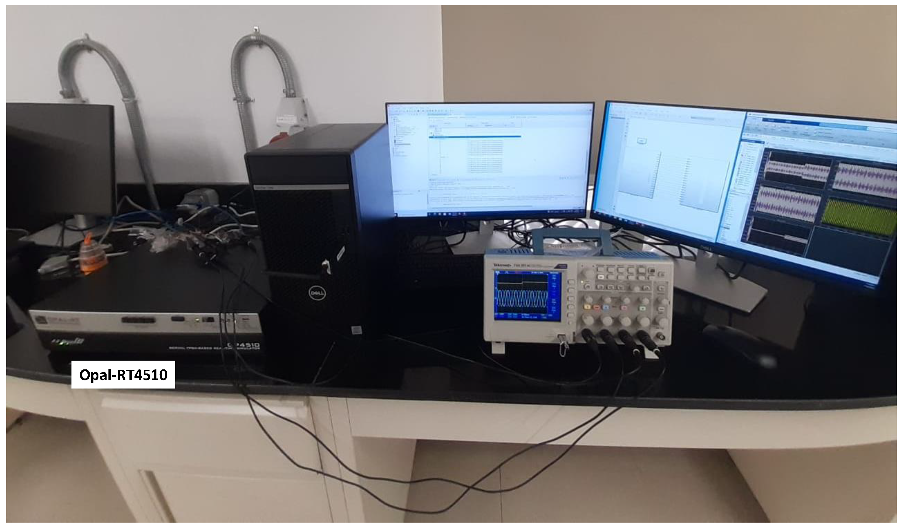
The setup based on the OPAL-RT 4510 platform (OPAL-RT Technologies, Montréal, QC, Canada) for the HiL experiment has been illustrated in Figure 6. The results are derived from an output voltage of 16 V, which represents the maximum output capability of the Opal (RT-Lab). Consequently, all reference values for power, voltage, and currents are scaled to this 16 V level.
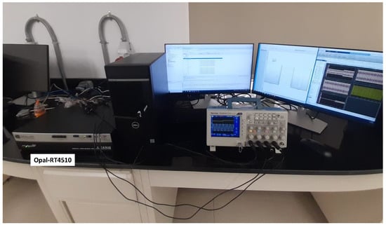
Figure 6.
The real-time simulation HiL configuration employed in the OPAL-RT 4510 platform.
The complete set of parameters’ values regarding the PV/BESS hybrid system are listed in Table 3. For the PV system, at an irradiance level of 1000 W/M2, a peak power output of 800 kW is generated. The PV voltage reaches a maximum of 1050 V, while the PV current attains 730 A at its MPP operating condition. From the grid side, the power reference is set at 800 kW, with an Line-to-Line (L-L) current value of 2240 A and a grid voltage of 320 V L-L rms value. Moving to the BESS side, the reference ESS voltage is established at 1160 V.
Table 3.
HiL system parameters for the hybrid PV/BESS case study.
Consequently, the scaling factors for each side are as follows: for PV, the irradiation scaling factor is defined as (16/1000), the power scaling factor is calculated as (16/800,000), the current scaling factor is determined by (16/730), and the voltage scaling factor is specified as (16/1050). For the grid, the power scaling factor remains consistent at (16/800,000), the current scaling factor is set at (16/2240), and the AC voltage scaling factor is defined as (16/320). For the BESS, the voltage scaling factor is represented by (16/1160).
4.1. Response to a Dramatic Drop in Grid Voltage
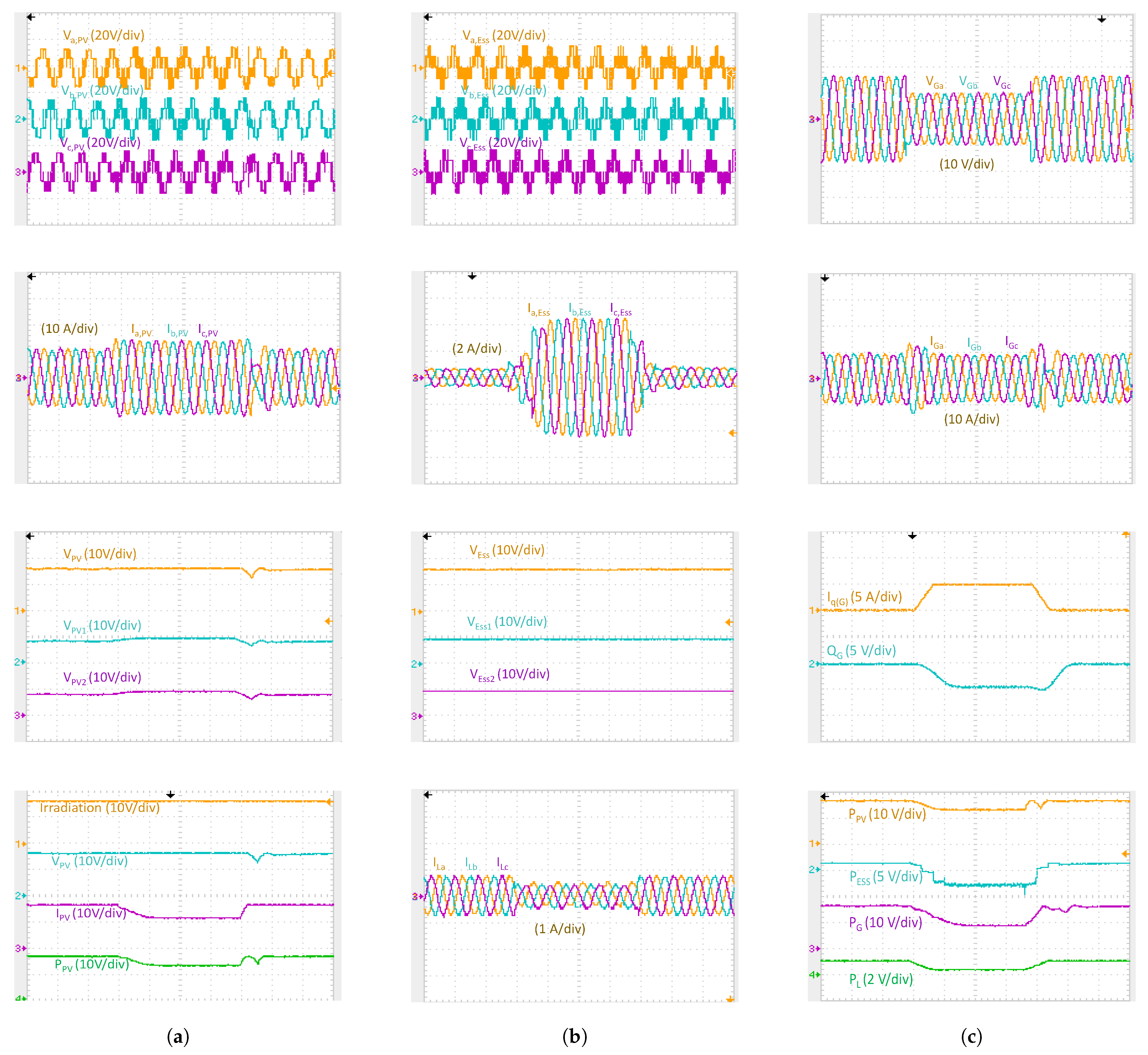
Conventional PV systems with a single stage frequently experience disconnection from the grid when the voltage decreases to a significant extent due to an overcurrent trip. This dilemma might create a chain reaction, bringing the distribution network to its knees. Here, as shown in Figure 7, a substantial decline in grid voltage () from 1 p.u. to 0.6 p.u. (a reduction of 40%) occurs at 0.3 s. Thereby, the control system prevents the grid from disconnection due to an overcurrent situation to improve the FRT operation of the system. In order to maintain grid stability for the duration of time stipulated by the grid code, the grid currents () may only increase to the predetermined level. Because of this, the grid power () is severely decreased. The PV Power () is reduced, and the active power injection into the grid is limited based on the depth of the voltage sag. This scenario is performed in order to maximize the injection of reactive power () to support the grid voltage () sag, as depicted in the figure. The ESS uses the extra power generated by the PVA, and it is demonstrated by the reversal of the ESS current () direction, which serves as an indicator of the ESS’s charging phase. The DC-link voltage () is held constant at this value; so, there is no variation in the capacitor voltage values (, , and , ) of the two converters. On the contrary, referring to the figure, the load current () exhibited a substantial reduction in accordance with the power magnitude. Finally, the grid voltage () returns to normal after 0.4 s, confirming that the issue has been resolved, and the system promptly reverts to its regular state at the predetermined grid power (). Also, the proposed FCSMPC achieved fast-tracking of the determined reference currents on the inverter system.
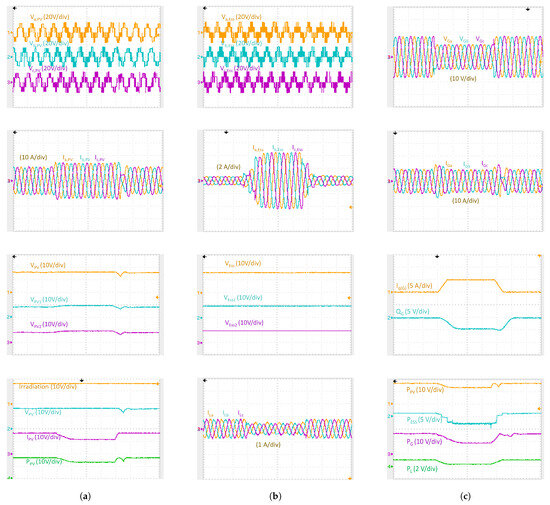
Figure 7.
Response to a dramatic drop in grid voltage: (a) PV side response, (b) ESS and load current side response, and (c) grid side response.
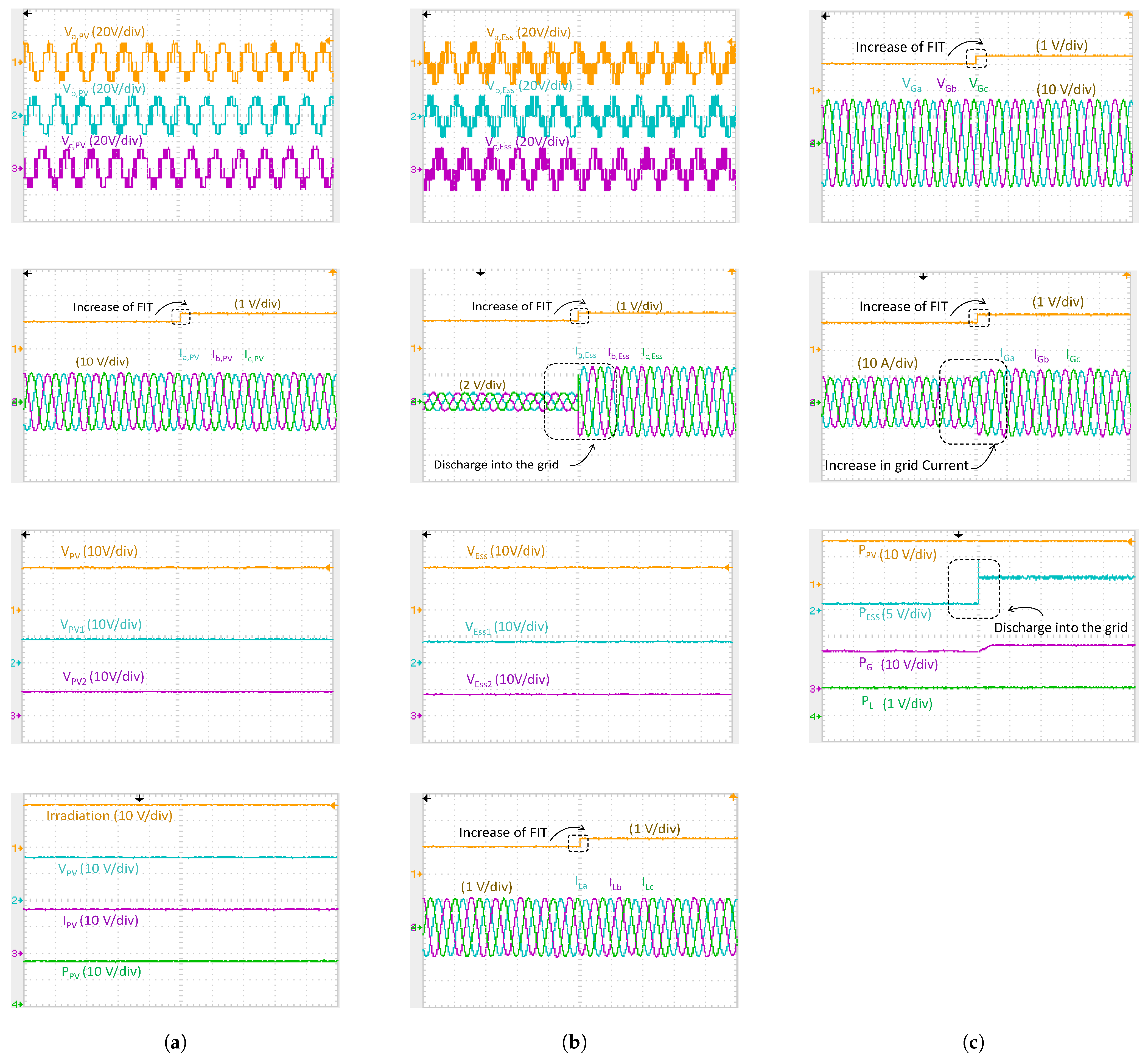
4.2. Investigation under Conditions of Unbalanced Grid Voltages
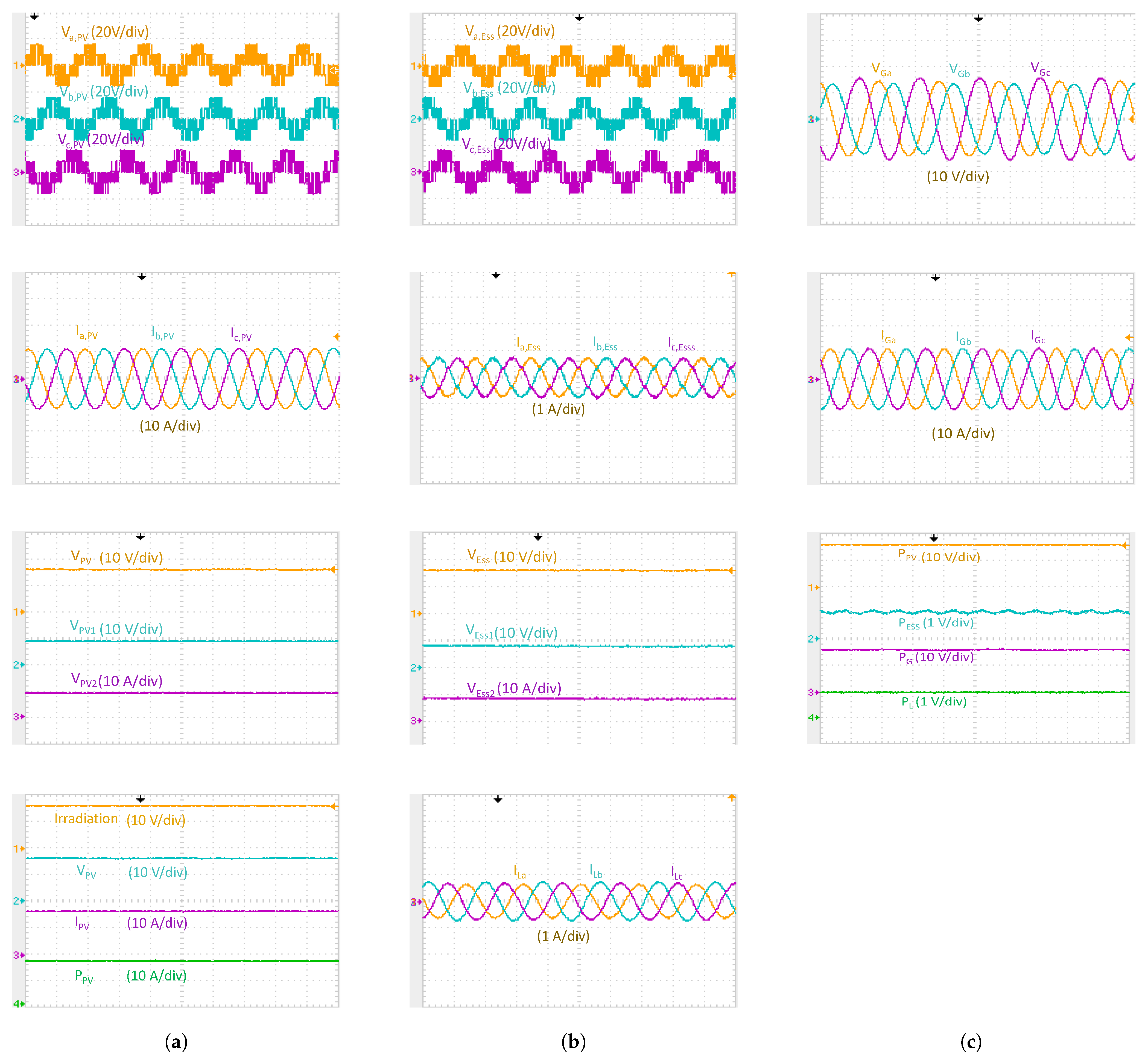
Unbalanced grid voltages, which are frequently observed in power systems with weak nature, give rise to asymmetrical grid currents in conventional systems. The efficacy of the control methodology presented is assessed through an analysis of the represented results in Figure 8. It is apparent that the amplitudes of the grid phase voltages () display dissimilarities, and there is a notable level of their imbalance. As a result, the concentration of the grid power () is sustained at the designated level. The PVA’s maximum power output remains unchanged. It is imperative to guarantee that the magnitude of grid current () remains equilibrated and comparable to its prior condition to uphold the specified grid power (). The proposed system and controller are capable of addressing the effects of asymmetrical loads and voltages at the PCC by introducing asymmetrical currents, resulting in the attainment of balanced instantaneous power.
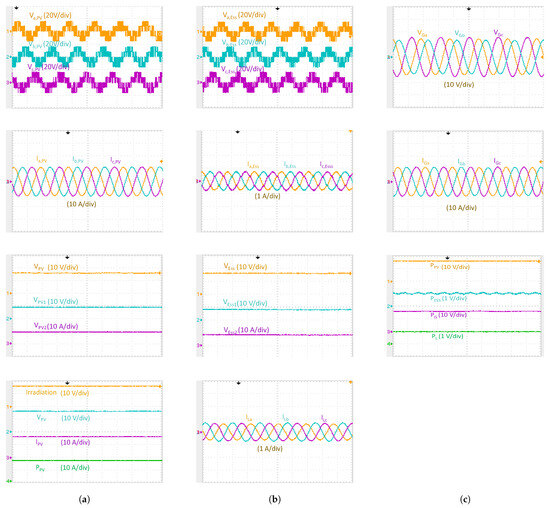
Figure 8.
Investigation under conditions of imbalanced grid voltages: (a) PV side response, (b) ESS and load current side response, and (c) grid side response.
4.3. The System’s Behavior under Dynamic Change in PV Power
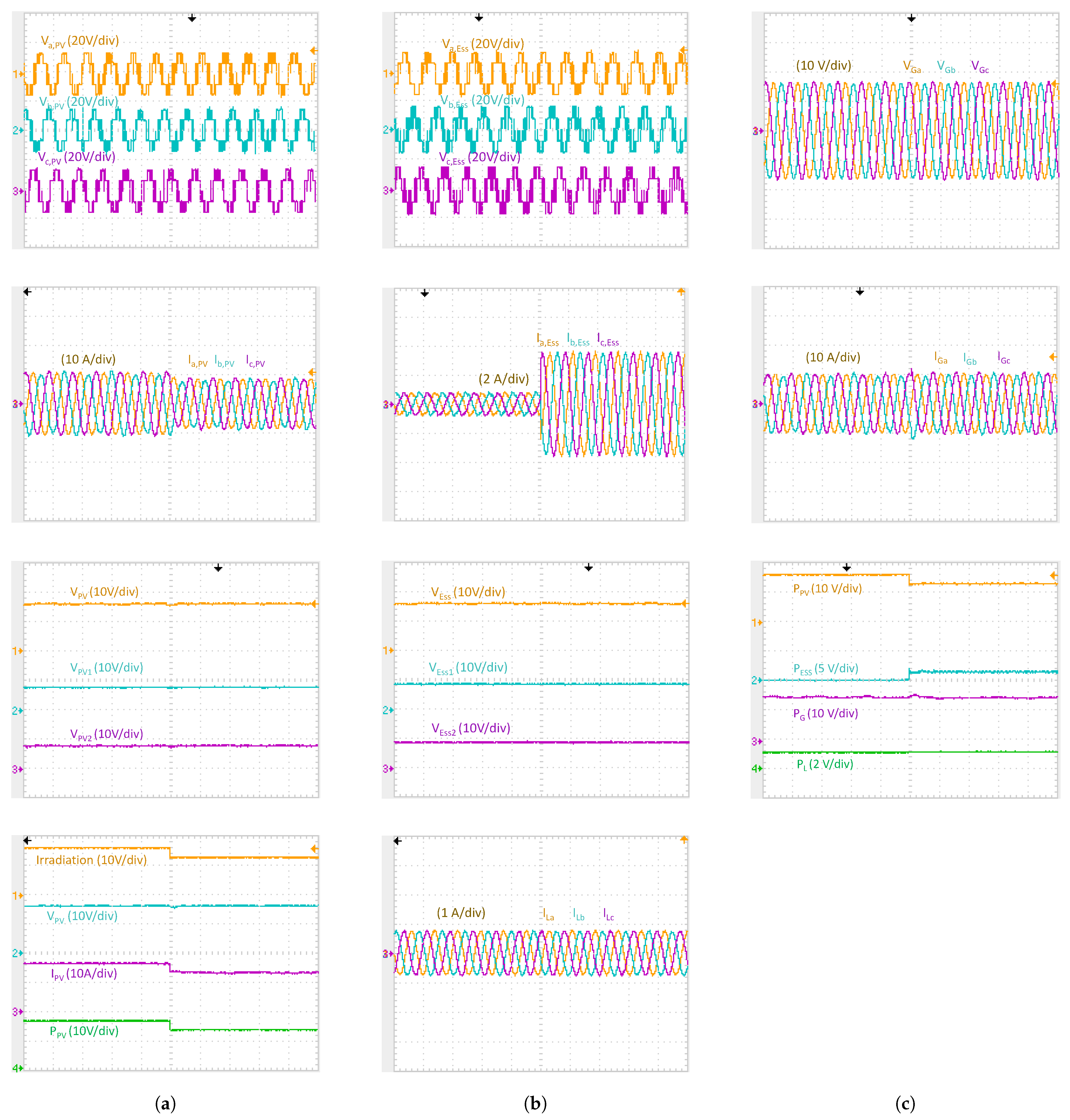
Due to the decrease in radiation from 1000 W/m2 to 800 W/m2, the PV power () diminishes by 20%. Consequently, the ESS discharges through the PCC to compensate for this reduction, ensuring the grid power () remains constant and unaffected. As depicted in Figure 9, the PV voltage () undergoes a negligible change, and the PV current () is diminished and influenced by the decrease in irradiation. Additionally, there is an increase in ESS current (), evident in the ESS power signal (), which rises to counterbalance the reduction in PV power(). Regarding the capacitor voltages of PV and ESS inverters (, , and , ), they remain unchanged in this scenario, as well as the load current () and load power ().
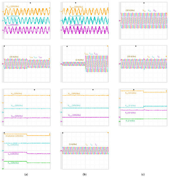
Figure 9.
Response to a dynamic change in PV power (reduction by ), (a) PV side response, (b) ESS and load current side response, and (c) grid side response.
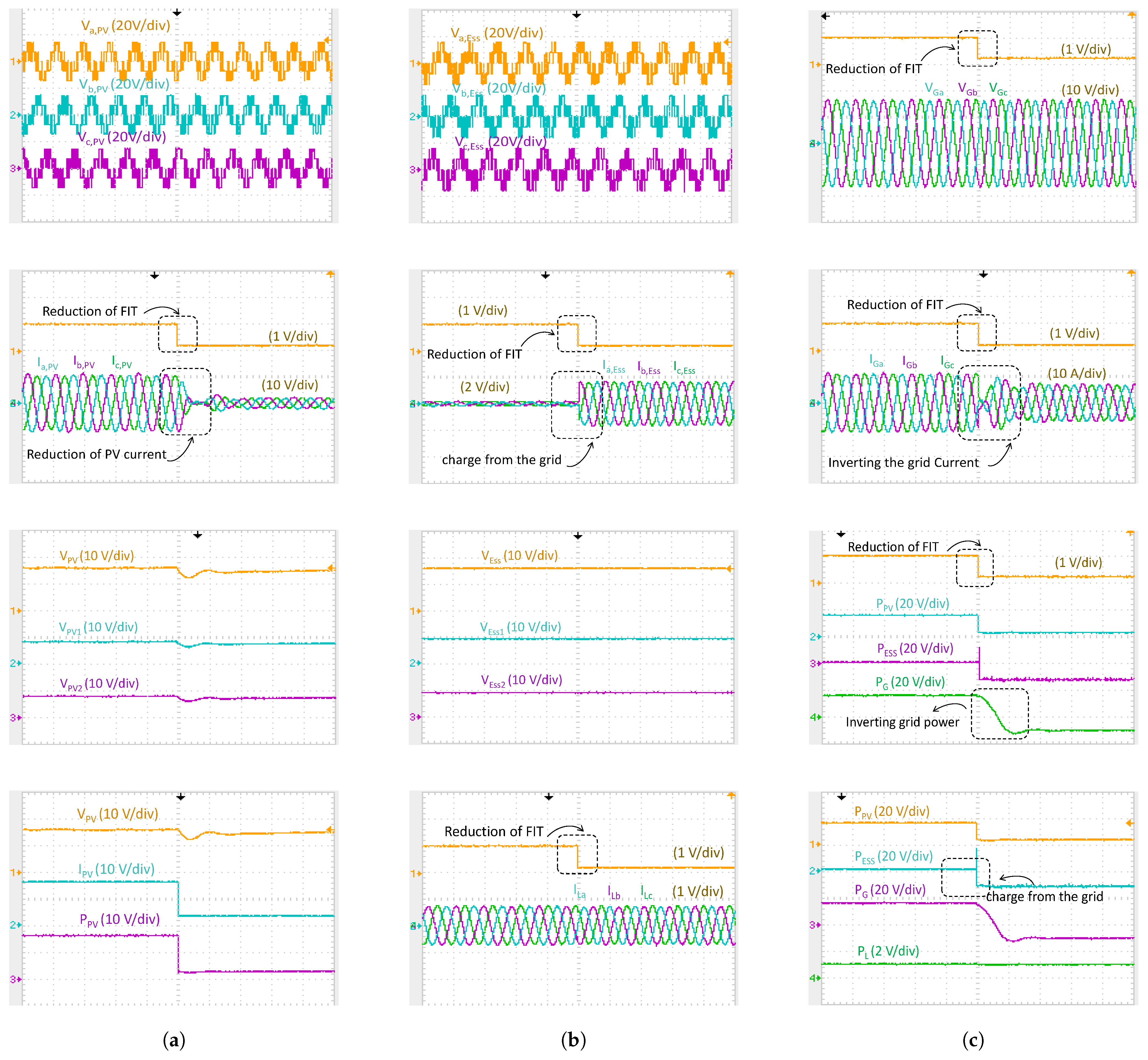
4.4. The System’s Behavior under Dynamic FiT
- At high FiT conditionThe system’s economic benefits are augmented by its adaptable power injection, which is activated by dynamic adjustments to the FiT. Figure 10 illustrates the observed system’s behavior and response at high FiT conditions. The FiT-MF has been noted to rise from 1 to 1.2, as shown in the figure. This implies a relationship between injecting grid power () and increasing earnings. Consequently, the ESS undergoes discharge, as indicated by the elevated ESS current (), aimed at boosting power delivery to the grid, and hence resulting in a positive value of ESS’s Power (). Consequently, grid current () experiences a rapid upsurge, indicating an increase in exported power to the grid. In contrast, the PVA operates under stable conditions with no variations in (), (), or (). Additionally, there are no discernible effects on DC-link capacitor voltages (, , , ) for both converters and load power ().
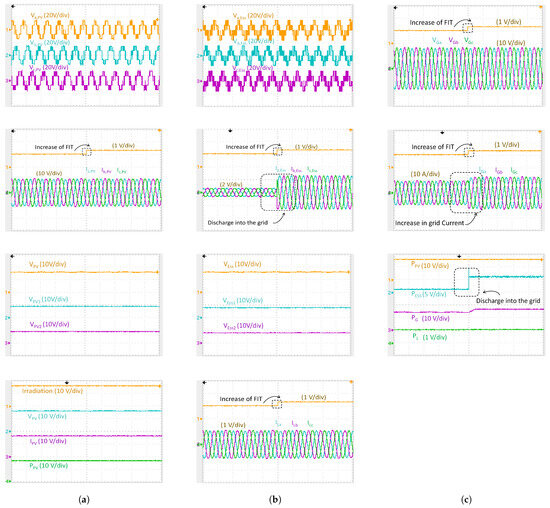
Figure 10.
The system’s behavior under high FiT: (a) PV side response, (b) ESS and load current side response, and (c) grid side response.
Figure 10.
The system’s behavior under high FiT: (a) PV side response, (b) ESS and load current side response, and (c) grid side response.
- At low FiT conditionAn examination of the response to a transition toward a lower FiT-MF of 0.2 is depicted in Figure 11. Currently, an economical energy source is available for supplying power to loads and recharging the ESS system. Consequently, the current flowing into the grid () is reversed, indicating the absorption of power from the grid, as evidenced by the grid power () signal reversing its direction. As for the ESS current (), it is inverted, signifying the process of ESS charging. Subsequently, the power generated by the PV system () is reduced. Concerning the capacitor voltages (, ) of the PV converter, they exhibit a slight decrease, influenced by the decline in PV power (), while there is no corresponding change in the ESS converter for (, ) voltages. The potential energy stored in the ESS system can be harnessed to enhance returns during periods of high FiT-MF.
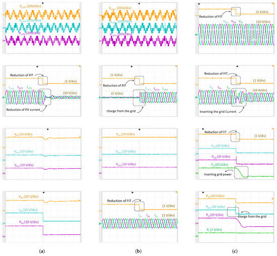 Figure 11. The system’s behavior under low FiT: (a) PV side response, (b) ESS and load current side response, and (c) grid side response.
4.5. Effect of Parameters Variations and System Uncertainties
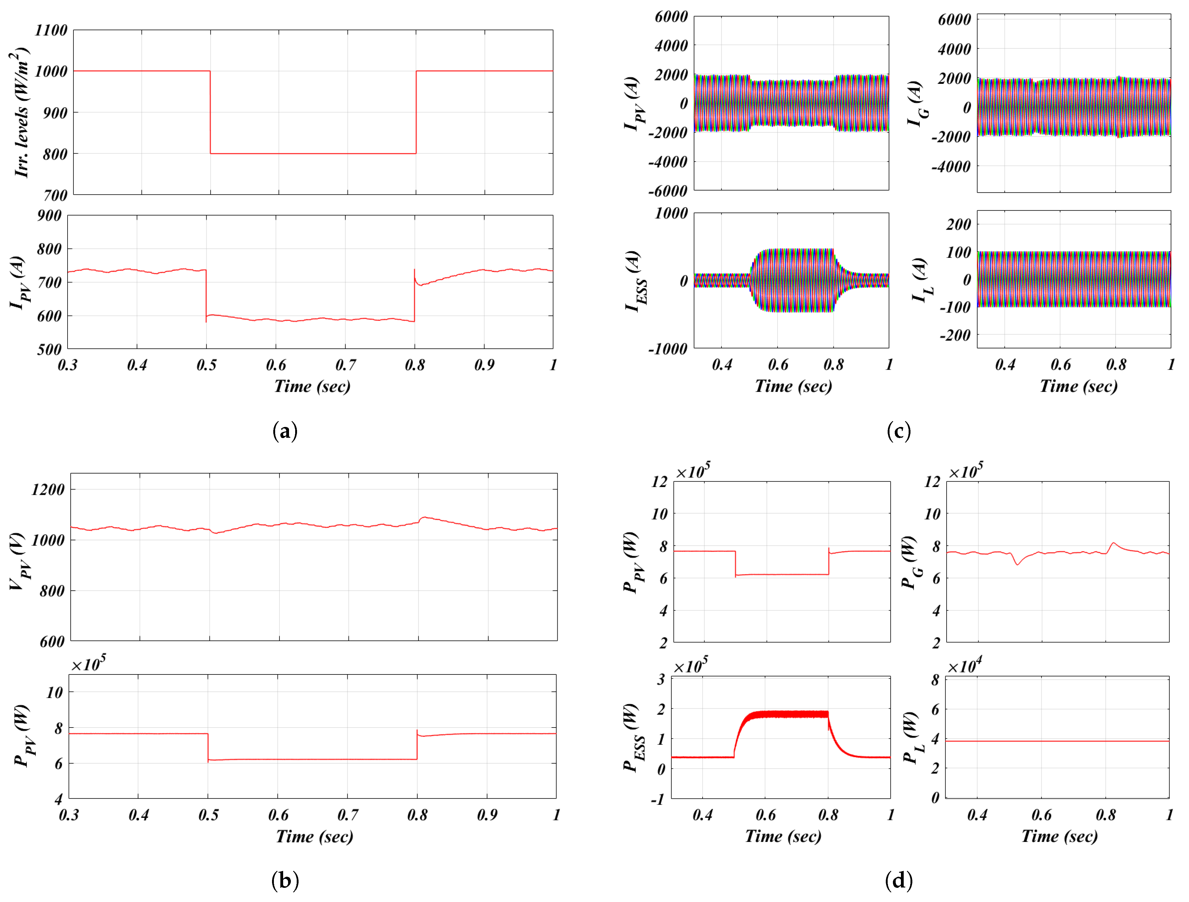
To highlight the effectiveness of the control system, its response under PV power uncertainty and varying solar irradiance levels has been studied, as shown in Figure 12. This figure illustrates the system’s rapid response to a step change in irradiation from 1000 W/m2 to 800 W/m2, followed by a return to normal irradiation levels. Furthermore, the proposed controller is capable of handling intermittent power generation from the PV system, As illustrated in the figure, the ESS inverter control detects the decrease in input PV power and quickly responds by discharging the ESS current through the DC link to maintain the grid power constant.
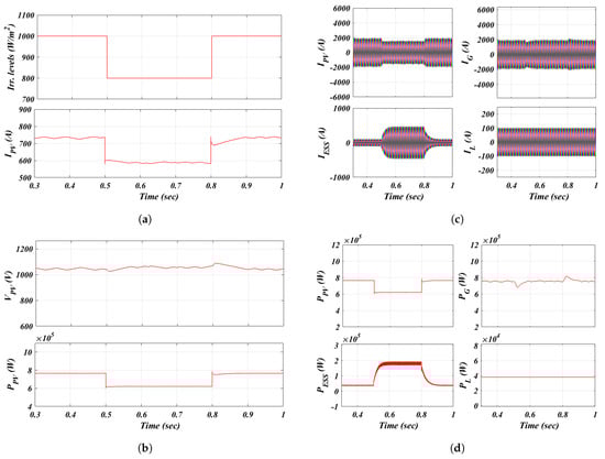
Figure 12.
The system’s response during PV power uncertainty: (a) irradiation level and PV current response, (b) PV voltage and PV power response, (c) PV, ESS, grid, and load current response, and (d) PV, ESS, grid, and load power response.
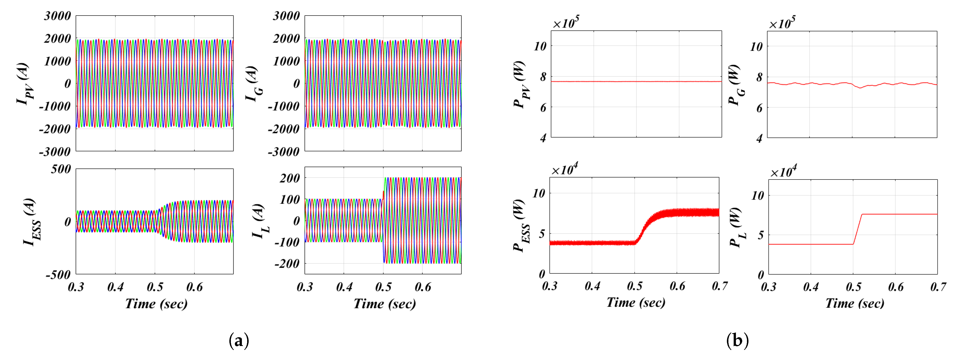
Another aspect of uncertainties is the system’s response to load variations, as demonstrated in Figure 13. At 0.5 s, the load has been doubled, and to maintain the grid power constant, the control of the ESS inverter responds to this variation, and the ESS compensates the load power. This is well demonstrated through the increase in the ESS current, increasing ESS power participation, while the grid and PV inverter currents remain unchanged.

Figure 13.
The system’s performance during load uncertainty: (a) PV, ESS, grid, and load current response; (b) PV, ESS, grid, and load power response.
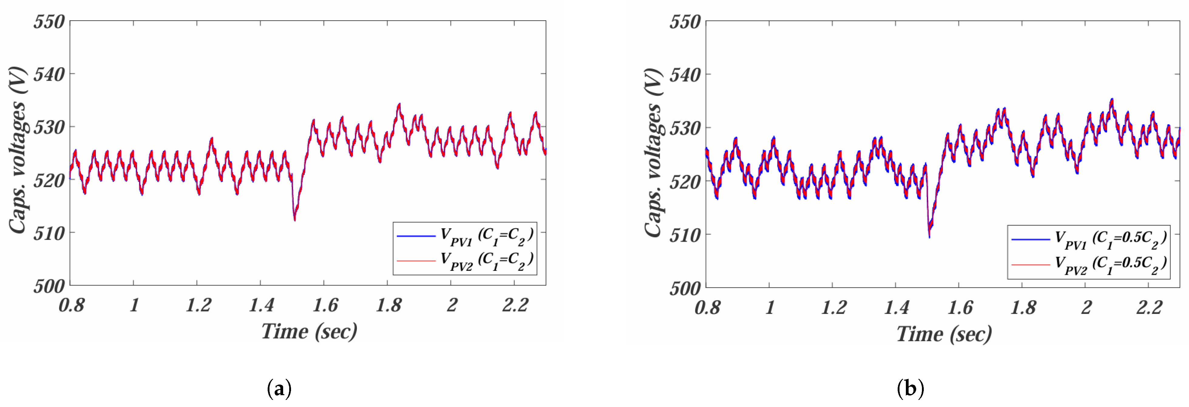
Regarding the response of the control system to parameter variations, Figure 14 illustrates the voltage balance across the two DC-link capacitors, considering their initially equal values in the NPC inverter and accounting for the aging factor over time, which causes these values to become unequal. The controller has demonstrated reliable operation in maintaining voltage balance between the two capacitors during a step change in input PV power at 1.5 s. The two cases represent the case when the DC-link capacitors are equal, and the case when one capacitor’s value is reduced to half of the other due to aging.
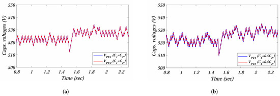
Figure 14.
Response of the control system to parameter variations: (a) capacitors’ voltages when , and (b) capacitors’ voltages when .
4.6. Comparing the Performance of the System Utilizing the MPC Approach with That of the Traditional PI Control
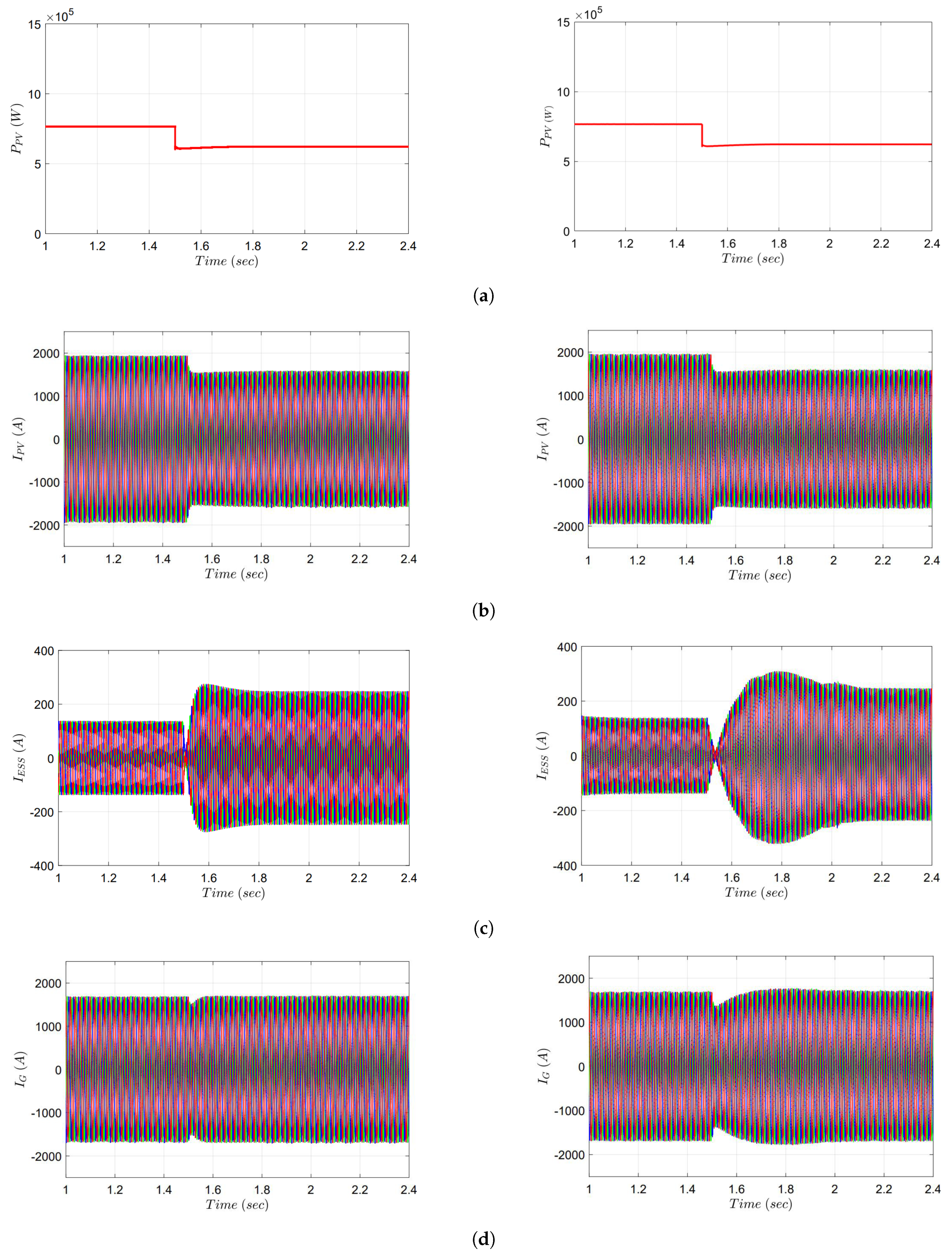
To validate the proposed system and highlight the advantages of MPC along with its superiority over traditional controls, a concise comparison is presented through Figure 15 (left), illustrating the system’s behavior with the MPC controller, and Figure 15 (right), showcasing the traditional PI controller. The employed controller parameters with PI-based control are PV inverter proportional gain and PV inverter integrator gain , and ESS inverter proportional gain and ESS inverter integrator gain . The switching frequency of the two converters is set to be constant at 5 kHz.
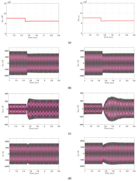
Figure 15.
The system’s response during the reduction in PV power with MPC control (left) and PI control (right): (a) Step change in the input PV power, (b) PV current response, (c) ESS current response, and (d) grid current response.
The comparison is conducted under the condition of reducing the PV power by at time s. The figures depict that the ESS compensates for the decrease in PV power to maintain constant grid power. Simultaneously, the ESS current discharges through the PCC.
As observed in the figures, MPC exhibits a rapid response compared to the PI controller, with the transient time for MPC being half that of the PI controller. The response time for PI is s, while it is s for MPC.
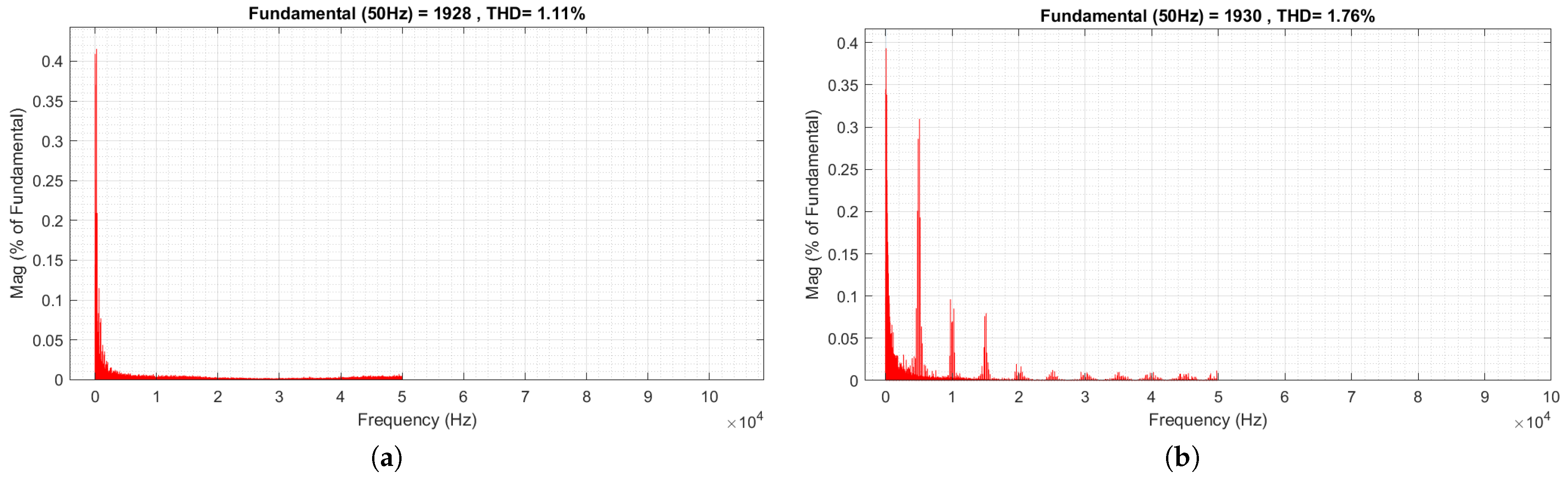
Analyzing the Total Harmonic Distortion (THD) of the PV inverter current in Figure 16, it is evident that the THD using MPC, which is recorded at , and is lower than its counterpart using the PI controller, which registers at .
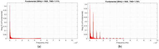
Figure 16.
The THD of the PV current: (a) PV current THD when employing MPC control, (b) PV current THD when employing PI control.
5. Conclusions and Future Work
This paper introduced an enhanced-performance single-stage hybrid PV–ESS system based on the FCSMPC technique that supports the bidirectional flow of power and improves the quality and techno-economic operation of grid power. The developed FCSMPC method offers a digital means to integrate various essential functionalities and adapt to multiple objectives based on grid, PV, load, and ESS conditions. The proposed system and control algorithm accomplished several tasks simultaneously, including MPPT control, ESS charging/discharging, support for weak grids, LVRT control, and handling unbalanced grid voltage conditions. Furthermore, the proposed system demonstrates economic efficiency by utilizing FiT during the reference current generation. A real-time HiL setup using the OPAL-RT platform for implementing the hybrid PV–ESS system with the FCSMPC algorithm has been applied to validate these improvements. This setup served to substantiate the claimed enhancements in system performance. Future research includes the extensions of this work to high-voltage ride-through scenarios, decoupling inverter systems, and application of other MPC algorithms.
Implementing the proposed hybrid PV–ESS system with an FCSMPC-based controller presents several challenges, including the computational intensity of real-time execution, precise grid synchronization, and handling aging components like capacitors in NPC inverters. Solutions include leveraging advanced processors like DSPs or FPGAs, implementing robust PLL techniques for synchronization, and using adaptive control strategies to compensate for aging effects. Economic viability can be improved through cost–benefit analysis and scaling the system based on demand. Ensuring compatibility with existing grid infrastructure and compliance with local regulations is essential. Real-time simulation testing, modular design, and technical staff training are critical for successful deployment, ensuring enhanced grid stability and optimized performance. All these aforementioned issues should be considered and accounted for in future research. Some issues related to FCSMPC implementations can be considered in future research, such as weighting factor design, implementation complexity, variable switching frequency, and model parameter dependency. In addition, communication-less techniques can be applied to parallel PV-BESS systems. Future research also includes studying the proposed method’s economic impacts using real mission profile data for the PV system and connected loads/grid systems.
Author Contributions
Conceptualization, F.S., M.A., T.F.M. and S.M.A.; methodology, F.S., M.A., T.F.M. and S.M.A.; software, F.S., M.A. and T.F.M.; validation, F.S., M.A. and T.F.M.; formal analysis, F.S., M.A., T.F.M. and S.M.A.; investigation, F.S., M.A., T.F.M., M.S. and S.M.A.; resources, F.S., M.A. and T.F.M.; data curation, F.S., M.A. and T.F.M.; writing—original draft preparation, F.S., M.A. and T.F.M.; writing—review and editing, F.S., M.A., T.F.M., M.S. and S.M.A.; visualization, F.S., M.A. and T.F.M.; supervision, M.S. and S.M.A.; project administration, F.S., M.A., T.F.M. and S.M.A.; funding acquisition, F.S. and M.A. All authors have read and agreed to the published version of the manuscript.
Funding
This work was supported by Vicerrectoría de Investigación y Doctorados de la Universidad San Sebastián—Fondo USS-FIN-24-APCS-22.
Institutional Review Board Statement
Not applicable.
Informed Consent Statement
Not applicable.
Data Availability Statement
Data are contained within the article.
Conflicts of Interest
The authors declare no conflicts of interest.
References
- Shawky, A.; Aly, M.; Rodriguez, J. Differential Inverters: A General Design Procedure Integrating a Novel Power Losses Modeling Approach for Utilized DC–DC Modules at Different Modulation Schemes. IEEE Access 2023, 11, 52790–52811. [Google Scholar] [CrossRef]
- Mukundan, C.M.N.; Naqvi, S.B.Q.; Singh, Y.; Singh, B.; Jayaprakash, P. A Cascaded Generalized Integral Control for Multiobjective Grid-Connected Solar Energy Transfer System. IEEE Trans. Ind. Electron. 2021, 68, 12385–12395. [Google Scholar] [CrossRef]
- Meng, Q.; Hussain, S.; Luo, F.; Wang, Z.; Jin, X. An Online Reinforcement Learning-based Energy Management Strategy for Microgrids with Centralized Control. IEEE Trans. Ind. Appl. 2024, 1–10. [Google Scholar] [CrossRef]
- Duan, Y.; Zhao, Y.; Hu, J. An initialization-free distributed algorithm for dynamic economic dispatch problems in microgrid: Modeling, optimization and analysis. Sustain. Energy Grids Netw. 2023, 34, 101004. [Google Scholar] [CrossRef]
- Hu, J.; Shan, Y.; Xu, Y.; Guerrero, J.M. A coordinated control of hybrid ac/dc microgrids with PV-wind-battery under variable generation and load conditions. Int. J. Electr. Power Energy Syst. 2019, 104, 583–592. [Google Scholar] [CrossRef]
- Zeraati, M.; Hamedani Golshan, M.E.; Guerrero, J.M. Distributed Control of Battery Energy Storage Systems for Voltage Regulation in Distribution Networks With High PV Penetration. IEEE Trans. Smart Grid 2018, 9, 3582–3593. [Google Scholar] [CrossRef]
- Wu, D.; Tang, F.; Dragicevic, T.; Vasquez, J.C.; Guerrero, J.M. A Control Architecture to Coordinate Renewable Energy Sources and Energy Storage Systems in Islanded Microgrids. IEEE Trans. Smart Grid 2015, 6, 1156–1166. [Google Scholar] [CrossRef]
- Shirkhani, M.; Tavoosi, J.; Danyali, S.; Sarvenoee, A.K.; Abdali, A.; Mohammadzadeh, A.; Zhang, C. A review on microgrid decentralized energy/voltage control structures and methods. Energy Rep. 2023, 10, 368–380. [Google Scholar] [CrossRef]
- Ju, Y.; Liu, W.; Zhang, Z.; Zhang, R. Distributed Three-Phase Power Flow for AC/DC Hybrid Networked Microgrids Considering Converter Limiting Constraints. IEEE Trans. Smart Grid 2022, 13, 1691–1708. [Google Scholar] [CrossRef]
- Sera, D.; Mathe, L.; Kerekes, T.; Spataru, S.V.; Teodorescu, R. On the Perturb-and-Observe and Incremental Conductance MPPT Methods for PV Systems. IEEE J. Photovolt. 2013, 3, 1070–1078. [Google Scholar] [CrossRef]
- Esram, T.; Chapman, P.L. Comparison of Photovoltaic Array Maximum Power Point Tracking Techniques. IEEE Trans. Energy Convers. 2007, 22, 439–449. [Google Scholar] [CrossRef]
- Hamzeh, M.; Emamian, S.; Karimi, H.; Mahseredjian, J. Robust Control of an Islanded Microgrid Under Unbalanced and Nonlinear Load Conditions. IEEE J. Emerg. Sel. Top. Power Electron. 2016, 4, 512–520. [Google Scholar] [CrossRef]
- Kai, S.; Zhang, F.; Huang, P. Coordinated Switching Control Strategy of Energy Storage in the PV-ESS hybrid System. In Proceedings of the 2021 4th International Conference on Energy, Electrical and Power Engineering (CEEPE), Chongqing, China, 23–25 April 2021; IEEE: Piscataway, NJ, USA, 2021. [Google Scholar] [CrossRef]
- Patra, S.; Bahloul, M.; Trivedi, R.; Khadem, S. Smart bi-directional inverter control and PV-ESS integration for net zero energy residential buildings. In Proceedings of the 13th Mediterranean Conference on Power Generation, Transmission, Distribution and Energy Conversion (MEDPOWER 2022), Valletta, Malta, 7–9 November 2022; Institution of Engineering and Technology: London, UK, 2022. [Google Scholar] [CrossRef]
- Colak, I.; Kabalci, E.; Bayindir, R. Review of multilevel voltage source inverter topologies and control schemes. Energy Convers. Manag. 2011, 52, 1114–1128. [Google Scholar] [CrossRef]
- Amirnaser Yazdani, R.I. Voltage-Sourced Converters in Power Systems: Modeling, Control, and Applications; IEEE Press/John Wiley: New York, NY, USA, 2010. [Google Scholar]
- Singh, B.; Singh, B.; Chandra, A.; Al-Haddad, K.; Pandey, A.; Kothari, D. A review of three-phase improved power quality AC-DC converters. IEEE Trans. Ind. Electron. 2004, 51, 641–660. [Google Scholar] [CrossRef]
- Prasad, K.K.; Myneni, H.; Kumar, G.S. Power Quality Improvement and PV Power Injection by DSTATCOM with Variable DC Link Voltage Control from RSC-MLC. IEEE Trans. Sustain. Energy 2019, 10, 876–885. [Google Scholar] [CrossRef]
- Kumar, S.; Patel, L.N.; Singh, B.; Vyas, A.L. Self-Adjustable Step-Based Control Algorithm for Grid-Interactive Multifunctional Single-Phase PV-Battery System Under Abnormal Grid Conditions. IEEE Trans. Ind. Appl. 2020, 56, 2978–2987. [Google Scholar] [CrossRef]
- Worku, M.Y.; Abido, M.A. Grid-connected PV array with supercapacitor energy storage system for fault ride through. In Proceedings of the 2015 IEEE International Conference on Industrial Technology (ICIT), Seville, Spain, 17–19 March 2015; IEEE: Piscataway, NJ, USA, 2015; pp. 2901–2906. [Google Scholar]
- Lin, F.J.; Lu, K.C.; Ke, T.H.; Yang, B.H.; Chang, Y.R. Reactive power control of three-phase grid-connected PV system during grid faults using Takagi–Sugeno–Kang probabilistic fuzzy neural network control. IEEE Trans. Ind. Electron. 2015, 62, 5516–5528. [Google Scholar] [CrossRef]
- Liu, Y.; Huang, A.Q.; Tan, G.; Bhattacharya, S. Control strategy improving fault ride-through capability of cascade multilevel inverter based STATCOM. In Proceedings of the 2008 IEEE Industry Applications Society Annual Meeting, Edmonton, AB, Canada, 5–9 October 2008; IEEE: Piscataway, NJ, USA, 2008; pp. 1–6. [Google Scholar]
- Song, Q.; Liu, W. Control of a cascade STATCOM with star configuration under unbalanced conditions. IEEE Trans. Power Electron. 2009, 24, 45–58. [Google Scholar] [CrossRef]
- Yang, L.; Liu, W.; Peng, G.; Chen, Y.G.; Xu, Z. Coordinated-Control Strategy of Photovoltaic Converters and Static Synchronous Compensators for Power System Fault Ride-Through. Electr. Power Compon. Syst. 2016, 44, 1683–1692. [Google Scholar] [CrossRef]
- Sadeghkhani, I.; Golshan, M.E.H.; Guerrero, J.M.; Mehrizi-Sani, A. A current limiting strategy to improve fault ride-through of inverter interfaced autonomous microgrids. IEEE Trans. Smart Grid 2016, 8, 2138–2148. [Google Scholar] [CrossRef]
- Nasiri, M.; Arzani, A.; Guerrero, J.M. LVRT operation enhancement of single-stage photovoltaic power plants: An analytical approach. IEEE Trans. Smart Grid 2021, 12, 5020–5029. [Google Scholar] [CrossRef]
- Pei, X.; Kang, Y. Short-circuit fault protection strategy for high-power three-phase three-wire inverter. IEEE Trans. Ind. Inform. 2012, 8, 545–553. [Google Scholar] [CrossRef]
- Chiang, S.; Lin, C.; Yen, C. Current limitation control technique for parallel operation of UPS inverters. In Proceedings of the 2004 IEEE 35th Annual Power Electronics Specialists Conference (IEEE Cat. No. 04CH37551), Aachen, Germany, 20–25 June 2004; IEEE: Piscataway, NJ, USA, 2004; Volume 3, pp. 1922–1926. [Google Scholar]
- Bahramian-Habil, H.; Abyaneh, H.A.; Gharehpetian, G. Improving LVRT capability of microgrid by using bridge-type fault current limiter. Electr. Power Syst. Res. 2021, 191, 106872. [Google Scholar] [CrossRef]
- Said, S.M.; Abdel-Salam, M.; Nayel, M.; Hashem, M.; Kamel, S.; Jurado, F.; Ebeed, M. Optimal design and cost of superconducting magnetic energy storage for voltage sag mitigation in a real distribution network. J. Energy Storage 2023, 73, 108864. [Google Scholar] [CrossRef]
- Hashem, M.; Abdel-Salam, M.; Nayel, M.; El-Mohandes, M.T. Mitigation of voltage sag in a distribution system during start-up of water-pumping motors using superconducting magnetic energy storage: A case study. J. Energy Storage 2022, 55, 105441. [Google Scholar] [CrossRef]
- Said, S.M.; Aly, M.; Balint, H. An Efficient Reactive Power Dispatch Method for Hybrid Photovoltaic and Superconducting Magnetic Energy Storage Inverters in Utility Grids. IEEE Access 2020, 8, 183708–183721. [Google Scholar] [CrossRef]
- Yang, Y.; Blaabjerg, F. Low-Voltage Ride-Through Capability of a Single-Stage Single-Phase Photovoltaic System Connected to the Low-Voltage Grid. Int. J. Photoenergy 2013, 2013, 257487. [Google Scholar] [CrossRef]
- Ding, G.; Gao, F.; Tian, H.; Ma, C.; Chen, M.; He, G.; Liu, Y. Adaptive DC-Link Voltage Control of Two-Stage Photovoltaic Inverter During Low Voltage Ride-Through Operation. IEEE Trans. Power Electron. 2016, 31, 4182–4194. [Google Scholar] [CrossRef]
- Kim, D.; Ramadhan, U.F.; Islam, S.U.; Jung, S.; Yoon, M. Design and Implementation of Novel Fault Ride through Circuitry and Control for Grid-Connected PV System. Sustainability 2022, 14, 9736. [Google Scholar] [CrossRef]
- Singh, B.; Kumar, S. Distributed Incremental Adaptive Filter Controlled Grid Interactive Residential Photovoltaic-Battery Based Microgrid for Rural Electrification. IEEE Trans. Ind. Appl. 2020, 56, 4114–4123. [Google Scholar] [CrossRef]
- Kalla, U.K.; Kaushik, H.; Singh, B.; Kumar, S. Adaptive Control of Voltage Source Converter Based Scheme for Power Quality Improved Grid-Interactive Solar PV–Battery System. IEEE Trans. Ind. Appl. 2020, 56, 787–799. [Google Scholar] [CrossRef]
- Hu, J.; Guerrero, J.; Islam, S. Model Predictive Control for Microgrids: From Power Electronic Converters to Energy Management; Institution of Engineering and Technology: London, UK, 2021. [Google Scholar] [CrossRef]
- Hu, J.; Shan, Y.; Cheng, K.W.; Islam, S. Overview of Power Converter Control in Microgrids—Challenges, Advances, and Future Trends. IEEE Trans. Power Electron. 2022, 37, 9907–9922. [Google Scholar] [CrossRef]
- Aly, M.; Carnielutti, F.d.M.; Grigoletto, F.B.; Silveira, K.d.O.; Norambuena, M.; Kouro, S.; Rodriguez, J. Predictive Control of Common-Ground Five-Level PV Inverter without Weighting Factors and Reduced Computational Burden. IEEE J. Emerg. Sel. Top. Power Electron. 2023, 11, 4772–4783. [Google Scholar] [CrossRef]
- Khayat, Y.; Heydari, R.; Naderi, M.; Dragicevic, T.; Shafiee, Q.; Fathi, M.; Bevrani, H.; Blaabjerg, F. Decentralized Frequency Control of AC Microgrids: An Estimation-Based Consensus Approach. IEEE J. Emerg. Sel. Top. Power Electron. 2021, 9, 5183–5191. [Google Scholar] [CrossRef]
- Carnielutti, F.; Aly, M.; Norambuena, M.; Hu, J.; Guerrero, J.; Rodriguez, J. Model Predictive Control of Master-Slave Inverters Operating with Fixed Switching Frequency. In Proceedings of the 2023 IEEE 8th Southern Power Electronics Conference and 17th Brazilian Power Electronics Conference (SPEC/COBEP), Florianopolis, Brazil, 26–29 November 2023; pp. 1–6. [Google Scholar] [CrossRef]
- Zheng, C.; Dragicevic, T.; Blaabjerg, F. Current-Sensorless Finite-Set Model Predictive Control for LC-Filtered Voltage Source Inverters. IEEE Trans. Power Electron. 2020, 35, 1086–1095. [Google Scholar] [CrossRef]
- Norambuena, M.; Medina, F.; Carnielutti, F.; Aly, M.; Rodriguez, J. Hierarchical Control Based on MPC for a Smart-Grid Including Power Distribution. In Proceedings of the IECON 2023-49th Annual Conference of the IEEE Industrial Electronics Society, Singapore, 16–19 October 2023; pp. 1–7. [Google Scholar] [CrossRef]
- Naqvi, S.B.Q.; Singh, B. A PV-Battery System Resilient to Weak Grid Conditions With Regulated Power Injection and Grid Supportive Features. IEEE Trans. Sustain. Energy 2022, 13, 1408–1419. [Google Scholar] [CrossRef]
- Dong, C.; Zhou, R.; Li, J. Rushing for subsidies: The impact of feed-in tariffs on solar photovoltaic capacity development in China. Appl. Energy 2021, 281, 116007. [Google Scholar] [CrossRef]
- Huang, S.; Wu, Q. Dynamic Tariff-Subsidy Method for PV and V2G Congestion Management in Distribution Networks. IEEE Trans. Smart Grid 2019, 10, 5851–5860. [Google Scholar] [CrossRef]
- Nithya, C.; Roselyn, J.P. Multimode Inverter Control Strategy for LVRT and HVRT Capability Enhancement in Grid Connected Solar PV System. IEEE Access 2022, 10, 54899–54911. [Google Scholar] [CrossRef]
- Karamanakos, P.; Geyer, T. Guidelines for the Design of Finite Control Set Model Predictive Controllers. IEEE Trans. Power Electron. 2020, 35, 7434–7450. [Google Scholar] [CrossRef]
- Cortes, P.; Kouro, S.; La Rocca, B.; Vargas, R.; Rodriguez, J.; Leon, J.I.; Vazquez, S.; Franquelo, L.G. Guidelines for weighting factors design in Model Predictive Control of power converters and drives. In Proceedings of the 2009 IEEE International Conference on Industrial Technology, Churchill, VIC, Australia, 10–13 February 2009; pp. 1–7. [Google Scholar] [CrossRef]
- Narimani, M.; Wu, B.; Yaramasu, V.; Reza Zargari, N. Finite Control-Set Model Predictive Control (FCS-MPC) of Nested Neutral Point-Clamped (NNPC) Converter. IEEE Trans. Power Electron. 2015, 30, 7262–7269. [Google Scholar] [CrossRef]
- Li, L.; Zhou, H.; Luo, F.; Lin, X.; Han, Y. Control strategy for low voltage ride through (LVRT) operation of two-stage photovoltaic power generation system. In Proceedings of the 2018 IEEE 4th Southern Power Electronics Conference (SPEC), Singapore, 10–13 December 2018; IEEE: Piscataway, NJ, USA, 2018; pp. 1–6. [Google Scholar]

Disclaimer/Publisher’s Note: The statements, opinions and data contained in all publications are solely those of the individual author(s) and contributor(s) and not of MDPI and/or the editor(s). MDPI and/or the editor(s) disclaim responsibility for any injury to people or property resulting from any ideas, methods, instructions or products referred to in the content. |
© 2024 by the authors. Licensee MDPI, Basel, Switzerland. This article is an open access article distributed under the terms and conditions of the Creative Commons Attribution (CC BY) license (https://creativecommons.org/licenses/by/4.0/).