Article

Analysis of the Use of Energy Storage in the Form of Concrete Slabs as a Method for Sustainable Energy Management in a System with Active Thermal Insulation and Solar Collectors

Chair of Chemical and Process Engineering, Faculty of Chemical Engineering and Technology, Cracow University of Technology, Warszawska 24 Str, 31-155 Cracow, Poland
Sustainability 2024, 16(17), 7645; https://doi.org/10.3390/su16177645
Submission received: 10 May 2024 / Revised: 28 August 2024 / Accepted: 29 August 2024 / Published: 3 September 2024

Abstract

:
One effective approach to reducing the energy required for heating buildings is the use of active thermal insulation (ATI). This method involves delivering low-temperature heat to the exterior walls through a network of pipes carrying water. For ATI to be cost-effective, the energy supply must be affordable and is typically derived from geothermal or solar sources. Solar energy, in particular, requires thermal energy storage (TES) to manage the gap between summer and the heating season. A building that integrates various renewable energy systems and heating/cooling technologies should be managed efficiently and sustainably. The proper integration of these systems with smart management strategies can significantly lower a building’s carbon footprint and operational costs. This study analyzes the use of concrete slabs as a method for sustainable energy management in a system incorporating active thermal insulation and solar collectors. Using ambient temperature and solar radiation data specific to Cracow, Poland, the simulations evaluate the feasibility of employing a concrete slab positioned beneath the building as a thermal storage tank. The results reveal some drawbacks of using concrete slabs, including high temperatures that negatively affect system efficiency. Increased temperatures lead to higher heat losses, and during summer, inadequate insulation can cause additional heat leakage into the building. The findings suggest that water may be a more effective alternative for thermal energy storage.

1. Introduction

Recent advancements in science and technology have made generating electricity from various renewable sources more accessible. However, the real challenge lies in efficiently storing the generated energy. Utilizing building envelope systems, such as thermal batteries, to store and release energy on demand offers a promising solution. These systems can capture thermal energy during non-peak load hours or when abundant renewable resources like solar radiation and wind are available. Conversely, the stored energy can be used during peak loads or when renewable sources are unavailable [1].
Thermal energy storage (TES) is one of the most promising technologies for enhancing the efficiency of renewable energy sources and HVAC systems. The three most common types of seasonal TES are sensible heat storage, latent heat storage, and thermochemical heat storage. Iffa et al. [1] investigated the performance of energy storage (charging), energy release (discharging), and the active insulation system, both separately and as an integrated system.
Incorporating a TES system into the building envelope can significantly reduce energy demand. While numerous studies explore the applications of TES in buildings, few focus on its integration within the structure. Navarro [2] reviewed and classified thermal storage systems based on their location within the building envelope. Kashan [3] proposed an innovative approach for building-integrated solar thermal storage using insulated concrete form (ICF) foundation walls for residential buildings in cold climates (Canada).
The building envelope, which includes the walls, roof, and windows, is a major source of thermal energy loss, with walls alone accounting for 25–30% of these losses [4]. Achieving energy savings requires improving the thermal performance of exterior walls through effective insulation. High storage efficiency depends on insulation with superior thermal properties. However, in the context of TES, insulation has received limited attention, particularly regarding exergy loss under periodic operating conditions. In one study [5], an analytical solution for the transient heat conduction equation was derived, yielding a clear and concise expression of the average exergy loss rate under a typical operation mode, where internal temperature variations follow a rectangular wave function.
Latent heat thermal energy storage improves the efficiency of renewable energy utilization. Phase change materials (PCMs) offer a promising solution for reducing heating and cooling energy consumption when integrated into building envelopes. By incorporating PCMs, the energy demand for space heating and cooling can be significantly lowered, providing an effective passive cooling method and enhancing both energy efficiency and thermal comfort in buildings [6]. Dardouri et al. [7] conducted numerical simulations to optimize the energy performance of PCM-integrated building envelopes. Numerous studies have explored the optimal placement of PCMs and insulation, as well as how their combination can enhance a building’s thermal efficiency [8,9,10,11,12,13]. Recent research has focused on integrating PCMs with thermal insulation and their impact on energy savings. This combination offers a practical solution for improving the thermal inertia and resistance of buildings, leading to better energy efficiency and potentially achieving near-zero energy consumption [7,14,15,16,17,18,19,20,21]. Zhang and Yan [22] designed, evaluated, and optimized a hybrid sensible–latent heat thermal energy storage system. By incorporating natural stones to enhance heat transfer within a shell-and-tube unit, they developed a hybrid configuration that combines both sensible and latent heat storage, increasing the energy storage rate by 8.3% to 92.6%.
Reducing primary energy consumption in space heating is essential, and exploring all available strategies is crucial. Heat pumps have gained popularity as they can heat spaces using significantly less electricity than conventional heating systems. Additionally, technological advancements have led to more efficient domestic power stations that convert solar energy into electricity. However, it is important to consider that heat pumps depend on highly exergetic electricity, and photovoltaic cells have considerably lower efficiency compared to thermal solar collectors. The concept of using solar collectors to heat buildings is not new. Braun [23,24] provided a comprehensive analysis in 1981, developing an algorithm and presenting simulation results for heating a residential building with solar collectors. Li et al. [25] developed a system comprising a solar collector, a variable-volume water tank, and an auxiliary heat source for space heating. Their findings demonstrate that the innovative tank system provides 11.6% more useful heat and reduces system heat loss by 19% compared to conventional systems.
El-Sebaey et al. [26] provided a comprehensive review of various design and operating parameters that influence the thermal performance of flat-plate solar collectors. In a separate study, El-Sebaey et al. [27] evaluated the thermal performance of two designs of flat-plate solar air heaters through experimental and CFD investigations. The studies [28,29] also explored the use of energy storage materials and solar collectors to enhance thermal performance.
The cost of the energy supply medium increases with the temperature required for heating a substance. For instance, during winter, it is more cost-effective to heat a room by supplying low-temperature heat to the cold air and raising it to a moderate temperature. To reach the target temperature only in the final stage, a more expensive high-temperature source is required. This idea was used in [30], where active thermal insulation was proposed. It works by introducing heat into the external walls of a building [31,32]. By utilizing low-temperature heat, it is possible to support heating more economically. However, active insulation serves primarily as an auxiliary heating method. The building still requires a primary heat source, and active insulation helps to significantly retain heat from this source. For active insulation to be cost-effective, the temperature of the low-temperature heat must be sufficiently high; otherwise, the savings would be minimal. In temperate climate conditions, using ground heat exchangers (without a heat pump) as low-temperature heat sources may present challenges.
The above considerations suggest that integrating solar space heating with active thermal insulation could be a promising approach. This combined solution has been explored in several studies. The first information on active thermal insulation concerns the Isomax Terrasol system [30], which consists of a solar collector and a ground storage tank for storing solar energy. Krzaczek and Kowalczuk [33] proposed using a medium with a constant inlet temperature of 17 °C throughout the year in active thermal insulation pipes. This consistent temperature maintains a steady direction of heat transfer from the inner surface toward the active insulation layer. Krecke et al. [34] provided details on the heat storage component used in the Isomax system, which is installed beneath the building as an insulated foundation slab. Kisilewicz et al. [35] presented long-term winter testing results for active thermal insulation (ATI). Kalus et al. [36] examined the integration of active thermal insulation (ATI) with thermal energy storage in the form of a 100 m², 0.2 m thick foundation slab powered by solar energy. They found that while this storage is inadequate for heating the entire house, it is effective for supplying active insulation during the heating season. Król and Kupiec [37] developed a guideline for the optimal placement of the active insulation layer in a building’s external wall. Their findings indicated that the practical location of active thermal insulation may not always align with the theoretical optimum due to significant variations in ambient temperature throughout the heating season.
Despite extensive research on methods to enhance the energy efficiency of systems using renewable energy for building heating and cooling, it is crucial, and perhaps even more important, to consider their effective and optimal integration when using more than one system. This study presents the results of an analysis of a system combining solar collectors with an underground energy storage system for solar energy, which can be used to power active thermal insulation placed in the building’s exterior walls. The feasibility of using concrete slabs as an energy storage medium for efficient utilization was examined. Ambient temperature and solar radiation data for Cracow, Poland [38], were used. The simulation focused on a typical single-family residential building.

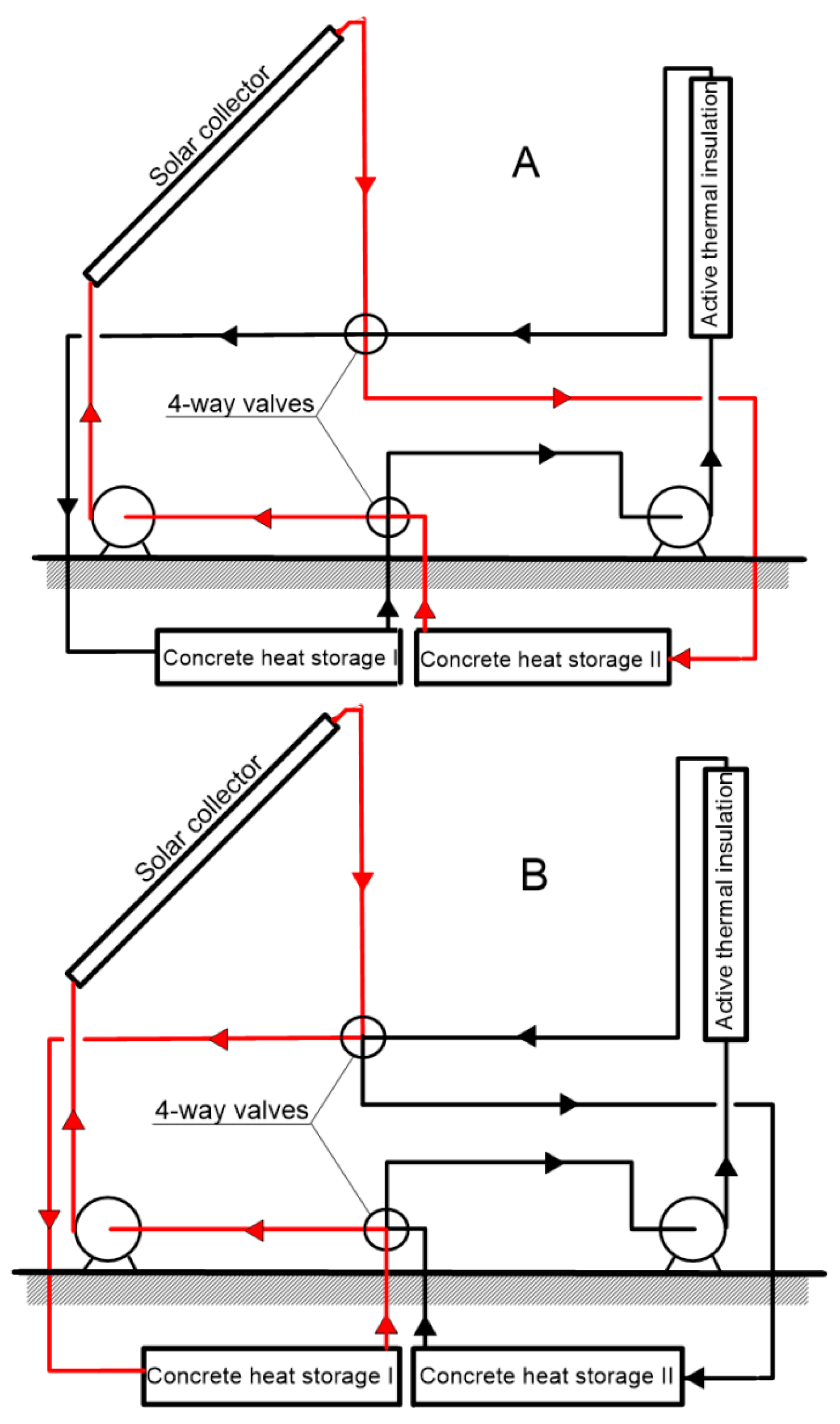
2. Description of the Mathematical Model

2.1. Assumptions

The current mathematical model simulates the heating support for a building using energy generated by solar collectors and delivered through the external walls via active thermal insulation. The simulation model is built on the following assumptions:
(1) The heat collected from the solar panels is stored in an underground concrete thermal energy storage system. This system comprises two slabs, designated as Slabs I and II, each equipped with pipes through which water circulates. These slabs are positioned beneath the building.
(2) The temperatures of the individual slabs in the thermal energy storage system are balanced.
(3) The room temperature is maintained at a constant level. The primary heating source ensures that a comfortable indoor temperature is upheld without the need for additional heat from the thermal energy storage system for active thermal insulation.
(4) When heat from the collector is directed to Slab I, the pipe system in Slab II is linked to the active thermal insulation (ATI) pipes. At regular intervals (monthly), the connections are switched: Slab I then connects to the ATI, while Slab II connects to the thermal energy storage system.
(5) The building’s external walls are constructed with three layers. The central layer consists of active thermal insulation made of concrete, which contains embedded pipes for water flow. Surrounding this ATI layer are layers of polystyrene insulation on both sides. For the analysis, the thermal resistances of both the ATI layer and the supporting wall are considered negligible.
(6) The temperature of the active thermal insulation (ATI) layer, Tw, and the temperature of the liquid exiting this layer are approximately equal. At the start of the heating season, Tw is maintained at a constant level. However, as the storage is depleted, Tw must be gradually reduced to ensure that the storage temperature does not fall below the minimum allowable temperature of Twmin by the end of the heating season.
(7) Heat losses in the pipes connecting the collector, the thermal energy storage, and the building are negligibly small.
(8) The concept of monthly utilizability is used to determine the useful energy produced by the collectors.
The interaction between the components involves heat transfer through closed-loop circuits of the working fluid. Flow diagrams of the working fluid are illustrated in Figure 1A,B.
In Figure 1A, the solar collector is connected to concrete thermal energy storage II, while thermal energy storage I is linked to the active thermal insulation. The red arrows represent the flow of the working fluid, which allows solar energy to be accumulated in thermal energy storage II. After a certain period, when thermal storage I is nearly depleted and storage II is adequately heated, the flow directions are reversed, as depicted in Scheme B. During this phase, the active thermal insulation is connected to thermal energy storage II, and the solar collector is redirected to storage I. The black arrows indicate the flow of the working fluid, which supplies the ATI layer with energy stored in concrete thermal energy storage II.

2.2. Usable Heat Produced in a Solar Collector

Monthly utilizability Φ ¯ represents the ratio of usable energy obtained per month to the amount of solar energy fed into the collector during that period. This quantity accounts for the fact that a portion of the solar energy remains unused when the radiant flux is lower than the heat loss flux from the collector to the environment. Consequently, the efficiency of utilization depends, among other factors, on the critical level of solar irradiance ITc:
I T c = U L T s t T a τ α
where
  • (τα)—effective transmittance–absorptance product, -;
  • UL—overall heat transfer coefficient between collector and environment, W/(m2K);
  • Ta—ambient temperature, °C;
  • Tst—the temperature at the inlet to the collector equals the temperature at the outlet from the thermal energy storage unit, °C.
The method of determining utilizability is described in detail in, among others, the monograph by Duffie and Beckman [24].
The model uses thermal energy balancing monthly. The amount of usable energy produced in the collector during the month Qu is described by the relation
Q u = A c F R τ α H ¯ T Φ ¯ Δ t
where
  • Ac—collector surface area, m2;
  • FR—collector heat removal factor, -;
  • H ¯ T —monthly average daily irradiation on a collector plane, J/(m2days);
  • Δt—the cycle duration (with a monthly cycle, the number of days or seconds in the month), s or days.

2.3. Concrete Thermal Storage

The concrete thermal storage system comprises two flat slabs with a total volume of Vst. Positioned beneath the building at a shallow depth below ground level, the storage is insulated on all sides. Pipes running through the center of each slab form a closed circuit that connects the storage slabs to a solar collector and/or active thermal insulation system.
Some of the stored energy is lost to the environment. The monthly energy loss QLst is represented by the formula
Q L s t = U s t A s t T s t T g Δ t
where
  • Ust—the overall heat transfer coefficient between the surface of the concrete slab walls with an average temperature of Tst and the ground with a temperature of Tg, W/(m2K).
The stored thermal energy is used to supply the active thermal insulation (ATI) layer situated in the building’s external walls. The thermal balance for the storage slab in conjunction with the solar collector is expressed as follows:
Δ U = Q u Q L s t
while for a slab coupled to the ATI layer, it is expressed as
Δ U = Q s t Q L s t
where
  • Qst—the amount of heat transferred from the storage to the ATI layer in one cycle (month), J.
The maximum amount of heat that can be transferred from the thermal storage to the building’s external wall during a time period Δt is
Q s t max = V s t / 2   c v T i T f min
where
  • Tfmin—the minimum acceptable storage temperature at the end of the cycle, °C.
  • Ti—storage temperature at the beginning of a given cycle (month), °C;
  • cv—volumetric heat capacity of the thermal energy storage (concrete), J/(m3K).
For each of the monthly cycles, the final temperature Tf should be determined as follows:
T f = Δ U V s t / 2 c v + T i

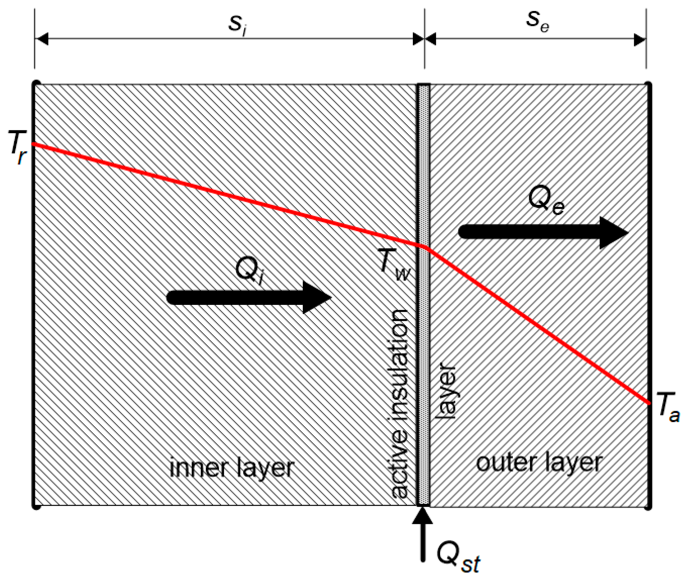
2.4. Active Thermal Insulation

Active thermal insulation functions to transfer low-temperature heat to the building’s external wall. This heat is conveyed through the working liquid circulating in the pipe system. The layer containing the pipes divides the insulation into two sections: an external part and an internal part. Figure 2 illustrates a cross section of the building’s external wall, which includes an inner layer of polystyrene insulation (i), the active thermal insulation layer, and an outer layer of polystyrene insulation (e).
The amount of heat transferred through the inner insulation layer during the time interval Δt is
Q i = T r T w R i A Δ t
Heat is transported through the outer layer in quantities of
Q e = T w T a R e A Δ t
In the absence of a heat supply to the ATI layer, the amount of heat lost from the room to the environment in time Δt is
Q 0 = T r T a R i + R e A Δ t
In the equations above, the symbol R represents thermal resistance, primarily composed of conduction resistance, as follows:
R s k i n s
where
  • s—insulation thickness, m,
  • kins—insulation conductivity, W/(mK).
The amount of heat transferred over time Δt between the thermal energy store and the ATI layer is as follows:
Q s t = Q e Q i
The relationship between the temperature of the ATI layer and the amount of heat transferred Qst is as follows:
T w = Q s t R r R e A Δ t + R e T r + R i T a R i + R e
In the summer, the heat demand for heating the ATI layer is zero. By substituting Qst = 0, the temperature of this layer can be determined in this case as the following:
T w 0 = R e T r + R i T a R i + R e

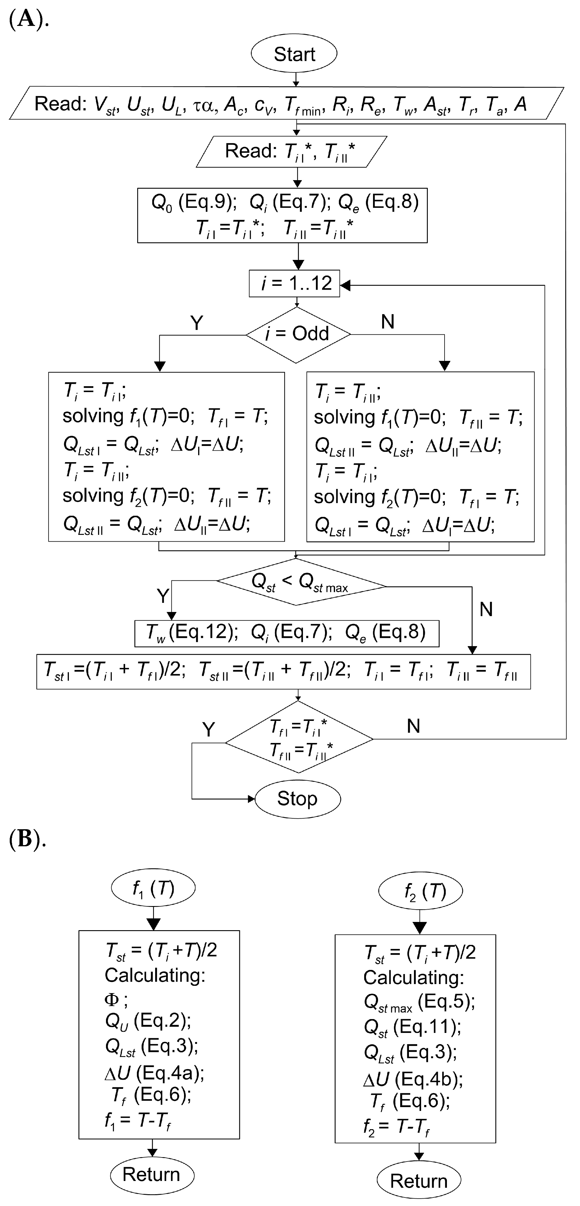
2.5. Calculation Algorithm

Calculations were conducted for each month of the year, starting in March when the charging/discharging cycle typically completes. Initial temperatures for both components of the storage system were established as baseline values. For each month, the calculation determines the temperature at the end of the month, which then serves as the initial temperature for the subsequent month. To ensure accuracy, the final temperature of the storage in the last month must match the initially assumed temperature, requiring an iterative approach [23]. The algorithm employed in this process is illustrated in Figure 3.
Solar radiation data for Cracow, Poland (50°03′41″ N 19°56′18″ E), were sourced from [38], while the ground temperature was determined using the relationships described in [39], which employed a four-parameter Carslaw–Jaeger equation [40]:
T = T s m A s exp x L cos ω t P s x L
where
  • x—depth, m;
  • L—damping depth, m;
  • Tsm—annually averaged value of the ground temperature, K;
  • As—amplitude of the ground temperature, K;
  • Ps—phase angle, rad;
  • ω (=2π/365)—frequency, days−1 or s−1.

2.6. Economic Analysis

To assess the impact of active thermal insulation, it is essential to compare the heat transferred through the inner layer of polystyrene insulation with and without the ATI layer, thereby evaluating the effectiveness of active thermal insulation versus passive insulation. With active insulation over the time interval Δt, this amount of heat is Qi, whereas, with passive insulation, the amount of heat is Q0. Thus, the economic factor can be formulated as
χ = Q 0 Q i Q 0
For passive insulation, where Qi = Q0, the efficiency factor χ is 0, indicating no additional heat gain. Conversely, if Qi = 0, χ equals 1, meaning that the heat lost from the interior is fully replaced by the heat provided by the active insulation layer. However, it is important to note that χ = 1 does not imply the complete elimination of internal space heating needs, as active thermal insulation (ATI) cannot offset ventilation losses. Additionally, substituting internal energy with ATI-supplied energy does not eliminate the cost of supplied energy but only reduces it. The energy required to transport working fluids to the ATI layer must be considered. Moreover, the energy loss through the outer polystyrene insulation layer must be factored into the economic analysis. Although the energy input to the ATI layer reduces the heat transported through the inner polystyrene insulation (Qi < Q0), it increases the heat transported through the outer polystyrene insulation layer (Qe > Q0).

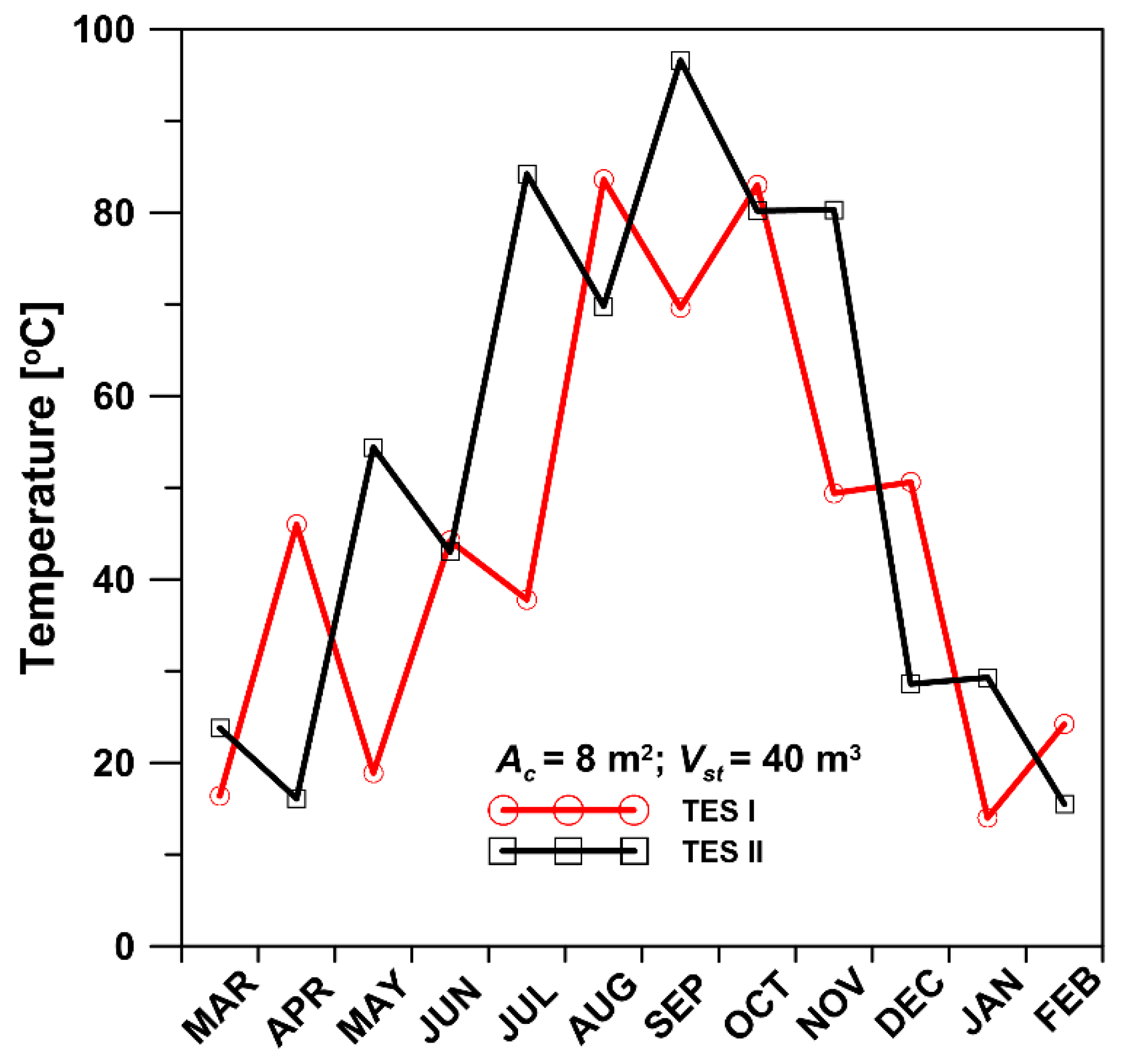
3. Results Discussion

The procedure described in Section 2.5 was employed to simulate domestic space heating using active thermal insulation. The relevant data for these calculations are presented in Table 1. The simulations were carried out for different values of the solar collector area Ac and different volumes of thermal energy storage Vst. The results obtained are presented in Figure 4, Figure 5, Figure 6, Figure 7 and Figure 8.
Figure 4 displays the temperature profiles of the building’s external wall for April (1) and November (2). As predicted by Fourier’s equation, the profiles are linear. The temperatures of the inner and outer surfaces of the walls were assumed to match the air temperatures on either side.
For example, in April, the average ambient temperature is 9.1 °C, while in November, it is 5.3 °C. Considering a longitudinal section of the wall located si away from the room, the temperatures there can be found according to relation (13).
When the center of the wall is considered (s = 2si), the corresponding temperatures are Tw01 = 14.55 °C and Tw02 = 12.65 °C.
If an ATI layer at a specific temperature is positioned at this point, the corresponding changes in heat transfer (or heat fluxes) can be assessed. For instance, if the ATI layer temperature is Tw = 16.5 °C, the temperature profile will intersect point B, as indicated by the dashed lines. This will lead to a change in the amount of heat transferred from the room to the active thermal insulation layer, shifting from Q0 (9) to Qi (7). The ratio of these amounts of heat is
Q i Q 0 = T r T w T r T a s s i
Based on Equation (13), it follows that
s s i = T r T a T r T w 0
From the last two formulae (16) and (17) and the definition of the χ coefficient (14), it follows that
χ = T w T w 0 T r T w 0 = B C ¯ A C ¯
where B C ¯ and A C ¯ are the lengths of the sections in Figure 4.
Thus, for November, B C 2 ¯ =16.5 − 12.65, while A C 2 ¯ = 20 − 12.65, which, according to relation (18), gives χ = 0.524. Similarly, the proportion of heat saved in April can be calculated as χ = 0.352.
Figure 5 illustrates the temperature variations of the thermal energy storages over the individual months. The temperatures of both storages alternately increase and decrease due to the cyclical charging and discharging processes. High temperatures in the concrete storage are detrimental to the system’s efficiency. As temperatures rise, heat losses escalate, and during the summer, insufficient insulation can lead to additional heat leakage into the building.
Figure 6 illustrates the impact of both the solar collector surface area and the storage volume on the maximum temperature achieved in the thermal energy storage. Both factors significantly influence the peak storage temperature: larger collector areas (Ac) and smaller storage volumes (Vst) lead to higher maximum temperatures. It is important to note that a temperature of 100 °C represents the upper limit when using water as the working fluid. The average TES temperatures for each month are shown in Figure 7 for Ac = 8 m2 and Vst = 40 m3.
The amount of heat transferred in the system fluctuates significantly throughout the year. The heat generated by the solar collectors, Qu, peaks in July and reaches its lowest point in December. Heat losses to the ground, QLst, exhibit a similar pattern but are delayed, with maximum losses occurring in August and September. The heat supplied to the active thermal insulation in the building wall, Qst, shows two peaks: one in spring and another in autumn. There is a notable gap in the heat supply from June to September. All these variations relating to the process occurring under Ac = 8 m2 and Vst = 40 m3 conditions are shown in Figure 8.
A significant amount of heat is lost from the thermal energy storage (TES) to the environment, accounting for about half of the heat supplied by the collectors. This loss is attributed to two main factors: the unfavorable shape of the storage and the high temperatures within it. Slab-shaped storage, with its large surface area relative to its volume, is less efficient compared to other shapes. For example, a cylindrical storage with a diameter equal to its height and a volume of 40 m3 has a surface area of 65 m2. In contrast, a slab-shaped storage with a thickness of 0.5 m and dimensions proportional to its volume has a surface area of 178 m2. Even excluding the top surface, this results in a significant exposure area of 98 m2.
The second reason for the substantial heat losses in concrete slabs is that concrete’s volumetric heat capacity is twice that of water. This higher capacity leads to significant temperature increases during heat transfer from the collectors, exacerbating heat loss.
In Figure 9, the variations of the economic factor χ are depicted for Vst = 50 m3 and different values of the collector area Ac. The values of χ are higher the larger the surface area of the installed collectors.

4. Conclusions

Utilizing active thermal insulation (ATI) for building heating significantly reduces costs by harnessing low-cost, low-temperature heat sources delivered to exterior walls. This approach is particularly valuable in capturing energy from solar collectors.
Emphasis should be placed on sustainably managing and storing the energy generated by solar panels for future use in powering the ATI layer. Solar energy storage should be optimized to minimize heat loss, ensuring that it remains a negligible proportion of the energy supplied to the storage system.
The shape of the storage system is crucial for minimizing the ratio of external surface area to volume, which helps reduce heat loss. Equally important is the specific heat capacity of the storage medium. However, simulation results suggest that the proposed solution of placing concrete slabs beneath the building has significant drawbacks. High temperatures within the concrete storage negatively impact system efficiency by increasing heat losses. During the summer, inadequate insulation can exacerbate this issue, leading to additional heat leakage into the building.
Future research should abandon the use of TES in the form of concrete slabs and instead explore water-based storage with a different configuration than slabs. Consideration should be given to using cylindrical storage with water as the thermal storage medium. Consequently, the results of this work provide a direction for further research on energy storage aimed at improving the energy efficiency of the active thermal insulation layer.

Funding

This research received no external funding.

Institutional Review Board Statement

Not applicable.

Informed Consent Statement

Not applicable.

Data Availability Statement

Dataset available on request from the author.

Conflicts of Interest

The author declares no conflicts of interest.

Nomenclature

Aenvelope of building area, m2;
Accollectors surface area, m2;
Asamplitude of the ground temperature, K;
cvvolumetric heat capacity of concrete, J/(m3K);
FRcollector heat removal factor;
H ¯ T monthly average daily irradiation on a collector plane, J/(m2day);
Ldamping depth, m;
Qthe amount of heat, J;
Psphase angle, rad;
Rthermal resistance, (m2K)/W;
ttime, s or days;
Ttemperature, °C;
Tsmannually averaged value of the ground temperature, K;
ULoverall heat transfer coefficient between collector and environment, W/(m2K);
Ustoverall heat transfer coefficient to the ground, W/(m2K);
Vstvolume of TES, m3;
xdepth, m;
βcollectors slope;
(τα)effective transmittance–absorptance product;
Φutilizability;
Φlatlatitude;
χeconomic factor, -;
ω (=2π/365)frequency, days−1 or s−1.
Subscripts
aambient;
eexternal;
iinitial or external;
rroom;
gground;
Llost;
ststorage;
wwall.

References

  1. Iffa, E.; Hun, D.; Salonvaara, M.; Shrestha, S.; Lapsa, M. Performance evaluation of a dynamic wall integrated with active insulation and thermal energy storage systems. J. Energy Storage 2023, 46, 103815. [Google Scholar] [CrossRef]
  2. Navarro, L.; de Gracia, A.; Colclough, S.; Browne, M.; McCormack, S.J.; Griffiths, P.; Cabeza, L.F. Thermal energy storage in building integrated thermal systems: A review. Part 1. active storage systems. Renew. Energy 2016, 88, 26–547. [Google Scholar] [CrossRef]
  3. Kashan, M.E.; Fung, A.S.; Eisapour, A.H. Insulated concrete form foundation wall as solar thermal energy storage for Cold-Climate building heating system. Energy Convers. Manag. X 2023, 19, 100391. [Google Scholar]
  4. Abanda, F.H.; Byers, L. An investigation of the impact of building orientation on energy consumption in a domestic building using emerging BIM (Building Information Modelling). Energy 2016, 97, 517–527. [Google Scholar] [CrossRef]
  5. Ai, W.; Wang, L.; Lin, X.; Zhang, S.; Bai, Y.; Chen, H. Mathematical and thermo-economic analysis of thermal insulation for thermal energy storage applications. Renew. Energy 2023, 213, 233–245. [Google Scholar] [CrossRef]
  6. Al-Yasiri, Q.; Szabó, M. Incorporation of phase change materials into building envelope for thermal comfort and energy saving: A comprehensive analysis. J. Build. Eng. 2021, 36, 102122. [Google Scholar] [CrossRef]
  7. Dardour, S.; Mankai, S.; Almoneef, M.M.; Mbarek, M.; Sghaier, J. Energy performance based optimization of building envelope containing PCM combined with insulation considering various configurations. Energy Rep. 2023, 10, 895–909. [Google Scholar] [CrossRef]
  8. Murathan, E.K.; Manioğlu, G. Evaluation of phase change materials used in building components for conservation of energy in buildings in hot dry climatic regions. Renew. Energy 2020, 162, 1919–1930. [Google Scholar] [CrossRef]
  9. Rai, A.C. Energy performance of phase change materials integrated into brick masonry walls for cooling load management in residential buildings. Build. Environ. 2021, 199, 107930. [Google Scholar] [CrossRef]
  10. Li, Z.X.; Al-Rashed, A.A.; Rostamzadeh, M.; Kalbasi, R.; Shahsavar, A.; Afrand, M. Heat transfer reduction in buildings by embedding phase change material in multi-layer walls: Effects of repositioning, thermophysical properties and thickness of PCM. Energy Convers. Manag. 2019, 195, 43–56. [Google Scholar] [CrossRef]
  11. Sharma, V.; Rai, A.C. Performance assessment of residential building envelopes enhanced with phase change materials. Energy Build. 2020, 208, 109664. [Google Scholar] [CrossRef]
  12. Sun, X.; Zhang, Y.; Xie, K.; Medina, M.A. A parametric study on the thermal response of a building wall with a phase change material (PCM) layer for passive space cooling. J. Energy Storage 2022, 47, 103548. [Google Scholar] [CrossRef]
  13. Kishore, R.A.; Bianchi, M.V.; Booten, C.; Vidal, J.; Jackson, R. Parametric and sensitivity analysis of a PCM-integrated wall for optimal thermal load modulation in lightweight buildings. Appl. Therm. Eng. 2021, 187, 116568. [Google Scholar] [CrossRef]
  14. Kishore, R.A.; Bianchi, M.V.; Booten, C.; Vidal, J.; Jackson, R. Enhancing building energy performance by effectively using phase change material and dynamic insulation in walls. Appl. Energy 2021, 283, 116306. [Google Scholar] [CrossRef]
  15. Al-Yasiri, Q.; Szabó, M. Building envelope-combined phase change material and thermal insulation for energy-effective buildings during harsh summer: Simulation-based analysis. Energy Sustain. Dev. 2023, 72, 326–339. [Google Scholar] [CrossRef]
  16. Kalbasi, R.; Afrand, M. Which one is more effective to add to building envelope: Phase change material, thermal insulation, or their combination to meet zero-carbon-ready buildings? J. Clean. Prod. 2022, 367, 133032. [Google Scholar] [CrossRef]
  17. Abden, M.J.; Tao, Z.; Alim, M.A.; Pan, Z.; George, L.; Wuhrer, R. Combined use of phase change material and thermal insulation to improve energy efficiency of residential buildings. J. Energy Storage 2022, 56, 105880. [Google Scholar] [CrossRef]
  18. Arumugam, P.; Ramalingam, V.; Vellaichamy, P. Effective PCM, insulation, natural and/or night ventilation techniques to enhance the thermal performance of buildings located in various climates—A review. Energy Build. 2022, 258, 111840. [Google Scholar] [CrossRef]
  19. Kurnia, J.C.; Haryoko, L.A.; Taufiqurrahman, I.; Chen, L.; Jiang, L.; Sasmito, A.P. Optimization of an innovative hybrid thermal energy storage with phase change material (PCM) wall insulator utilizing taguchi method. J. Energy Storage 2022, 49, 104067. [Google Scholar] [CrossRef]
  20. Solgi, E.; Hamedani, Z.; Fernando, R.; Kari, B.M. A parametric study of phase change material characteristics when coupled with thermal insulation for different Australian climatic zones. Build. Environ. 2019, 163, 106317. [Google Scholar] [CrossRef]
  21. Arumugam, P.; Ramalingam, V.; Vellaichamy, P. Optimal positioning of phase change material and insulation through numerical investigations to reduce cooling loads in office buildings. J. Energy Storage 2022, 52, 104946. [Google Scholar] [CrossRef]
  22. Zhang, S.; Yan, Y. Evaluation and optimisation of hybrid sensible-latent heat thermal energy storage unit with natural stones to enhance heat transfer. Renew. Energy 2023, 215, 118921. [Google Scholar] [CrossRef]
  23. Braun, J.E.; Klein, S.A.; Mitchell, J.W. Seasonal storage of energy in solar heating. Sol. Energy 1981, 26, 403–411. [Google Scholar] [CrossRef]
  24. Duffie, J.A.; Beckman, W.A. Solar Engineering of Thermal Processes, 4th ed.; John Wiley & Sons, Inc.: Hoboken, NJ, USA, 2013; p. 928. [Google Scholar]
  25. Li, J.; Li, X.; Wang, Y.; Tu, J. Long-term performance of a solar water heating system with a novel variable-volume tank. Renew. Energy 2021, 164, 230–241. [Google Scholar] [CrossRef]
  26. El-Sebaey, M.S.; Mousavi, S.M.T.; Sathyamurthy, R.; Panchal, H.; Essa, F.A. A detailed review of various design and operating parameters affecting the thermal performance augmentation of flat-plate solar collectors. Int. J. Ambient. Energy 2024, 45, 2351100. [Google Scholar] [CrossRef]
  27. El-Sebaey, M.S.; Ellman, A.; El-Din, S.S.; Essa, F.A. Thermal Performance Evaluation for Two Designs of Flat-Plate Solar Air Heater: An Experimental and CFD Investigations. Processes 2023, 11, 1227. [Google Scholar] [CrossRef]
  28. El-Sebaey, M.S. Proposing novel approach for indirect solar dryer integrated with active-fan and passive-chimney: An experimental and analytical investigation. Energy 2024, 304, 132215. [Google Scholar] [CrossRef]
  29. Sathyamurthy, R.; Ali, H.M.; Said, Z.; Kabeel, A.E.; El-Sebaey, M.S.; Gopalsamy, S.; Nagaraj, M.; Almasoud, N.; Alomar, T.S. Enhancing solar still thermal performance: The role of surface coating and thermal energy storage in repurposed soda cans. J. Energy Storage 2024, 77, 109807. [Google Scholar] [CrossRef]
  30. Isomax-Terrasol. Available online: https://isomax-terrasol.eu/ (accessed on 28 August 2024).
  31. Meggers, F.; Baldini, L.; Leibundgut, H. An innovative use of renewable ground heat for insulation low energy building system. Energies 2012, 5, 3149–3166. [Google Scholar] [CrossRef]
  32. Shen, C.; Li, X. Energy saving potential of pipe-embedded building envelope utilizing low-temperature hot water in the heating season. Energy Build. 2017, 138, 318–331. [Google Scholar] [CrossRef]
  33. Krzaczek, M.; Kowalczuk, Z. Thermal Barrier as a technique of indirect heating and cooling for residential buildings. Energy Build. 2011, 4, 823–837. [Google Scholar] [CrossRef]
  34. Krecke, E.; Ulbrich, R.; Radlak, G. Connection of Solar and Near-Surface Geothermal Energy in Isomax Technology. In Proceedings of the CESB 07 Prague International Conference, Prague, Czech Republic, 24–25 September 2007; pp. 622–628. [Google Scholar]
  35. Kisilewicz, T.; Fedorczak-Cisak, M.; Sadowska, B.; Ickiewicz, I.; Barkanyi, T.; Bomberg, M.; Gobcewicz, E. On the results of long-term winter testing of active thermal insulation. Energy Build. 2023, 296, 113412. [Google Scholar] [CrossRef]
  36. Kalus, D.; Janik, P.; Koudelkova, D.; Muckova, V.; Sokol, M. Contribution to research on ground heat storages as part of building energy systems using RES. Energy Build. 2022, 267, 112125C. [Google Scholar] [CrossRef]
  37. Król, B.; Kupiec, K. Optimal location of the active thermal insulation layer in the building envelope. Thermo 2023, 3, 176–199. [Google Scholar] [CrossRef]
  38. Photovoltaic Geographical Information System (PVGIS). Available online: https://joint-research-centre.ec.europa.eu/photovoltaic-geographical-information-system-pvgis_en (accessed on 28 August 2024).
  39. Larwa, B.; Kupiec, K. Heat transfer in the ground with a horizontal heat exchanger installed–Long-term thermal effect. Appl. Therm. Eng. 2020, 164, 114539. [Google Scholar] [CrossRef]
  40. Carslaw, H.S.; Jaeger, J.C. Conduction of Heat in Solids, 2nd ed.; Clarendon Press: Oxford, UK, 1959. [Google Scholar]
Figure 1. System set-up. (A). Solar energy feeds TES II. (B). Solar energy feeds TES I.
Sustainability 16 07645 g001
Figure 2. A cross section of the external wall of a building.
Sustainability 16 07645 g002
Figure 3. Calculation algorithm. (A). Main algorithm. (B). Computation of functions f1 and f2. * means the assumed temperature.
Sustainability 16 07645 g003
Figure 4. The temperature profiles in the wall.
Sustainability 16 07645 g004
Figure 5. Monthly temperatures in storages I and II.
Sustainability 16 07645 g005
Figure 6. Maximum temperatures of TES.
Sustainability 16 07645 g006
Figure 7. The average TES temperatures for each month for Ac = 8 m2 and Vst = 40 m3.
Sustainability 16 07645 g007
Figure 8. The variations of the quantities Qu, QLst, and Qst transferred in the investigated system.
Sustainability 16 07645 g008
Figure 9. The temporal variations of the economic factor χ for the different solar collector surface areas.
Sustainability 16 07645 g009
Table 1. Data used for simulations.
SymbolValue
Solar collectorsΦlat50°
β40°
FR0.95
UL2.78 W/(m2K)
(τα)0.75
Ac6 ÷ 10 m2
Concrete thermal energy storageVst30 ÷ 50 m3
cV2.4∙106 J/(m3K)
Ust0.08 W/(m2K)
Active thermal insulationRe2.5 m2K/W
Ri2.5 m2K/W
A250 m2
Tg2.4 ÷ 17.1 °C
Ta−7.6 ÷ 20.0 °C
Tr20 °C
Tw16.5 °C
H ¯ T (2.8 ÷ 19)∙109 J/(m2day)
Disclaimer/Publisher’s Note: The statements, opinions and data contained in all publications are solely those of the individual author(s) and contributor(s) and not of MDPI and/or the editor(s). MDPI and/or the editor(s) disclaim responsibility for any injury to people or property resulting from any ideas, methods, instructions or products referred to in the content.

