Article

Nonlinear Analysis of the Mechanical Response of an Existing Tunnel Induced by Shield Tunneling during the Entire Under-Crossing Process

1
State Key Laboratory of Bridge Safety and Resilience, Hunan University, Changsha 410082, China
2
School of Civil Engineering, Hunan University, Changsha 410082, China
*
Author to whom correspondence should be addressed.
Sustainability 2024, 16(18), 8224; https://doi.org/10.3390/su16188224
Submission received: 16 August 2024 / Revised: 14 September 2024 / Accepted: 19 September 2024 / Published: 21 September 2024
(This article belongs to the Section Sustainable Engineering and Science)

Abstract

:
The safety of existing tunnels during the entire under-crossing process of a new shield tunnel is critically important for ensuring the sustainable operation of urban transportation infrastructure. The nonlinear behavior of surrounding soils plays a significant role in the mechanical response of tunnel structures. In order to assess the mechanical response of the existing tunnel more reasonably, this study attempts to propose a novel theoretical solution and calculation method by simultaneously considering the nonlinear characteristics of surrounding soils and the tunneling effects of a new tunnel during its entire under-crossing process. Firstly, the additional stresses acting on the existing tunnel stemming from the tunneling effects of a new shield tunnel during different under-crossing stages are calculated using the typical Mindlin solution, as well as the Loganathan and Poulos solutions. The influences of the additional thrust, friction force, and grouting pressure and the loss of surrounding soils are taken into account. Then, the nonlinear Pasternak foundation model is introduced to characterize the behavior of surrounding soils, and the governing differential equation for the mechanical response of the existing tunnel is derived using the typical Euler–Bernoulli beam model. Subsequently, a novel theoretical solution and calculation approach are established using the finite difference formula and the Newton iteration method for assessing the mechanical response of the existing tunnel. Finally, one case study is performed to illustrate the mechanical behavior of the existing tunnel during the whole under-crossing process of a new shield tunnel, and the validity of the developed solution is verified against both the computed result of finite element simulation and the field measurements. In addition, the influences from the ultimate resistance and reaction coefficient of surrounding soils and those from the vertical distance and intersection angle between existing and newly constructed tunnels are analyzed and discussed in detail.

1. Introduction

In large cities, shield tunnels commonly play significant roles in the sustainable development of the economy, energy, and society. Because of the limitation of urban underground space, some new shield tunnels are generally constructed by under-crossing the existing tunnels. The under-crossing construction of a new shield tunnel inevitably disturbs the surrounding soils and subsequently brings about noticeable additional stresses on the existing tunnels above. These additional stresses often enlarge the displacement and internal forces of existing tunnels and even lead to some structural damages and disasters, such as differential settlement, lining cracks, and longitudinal dislocation [1,2,3,4]. Therefore, to ensure the safety of existing tunnels, it is crucial to predict the displacement and internal forces induced by a new shield tunnel during its entire under-crossing process reasonably and effectively.
In the past few decades, from various perspectives of theoretical analysis [5,6,7,8], finite element simulation [9,10,11], and model testing [12,13,14,15], extensive studies have been undertaken to study the mechanical behavior and response of existing tunnels during the under-crossing process of a new shield tunnel. Theoretical analysis, in contrast with finite element simulations and model tests, emerges as a more practical approach to predicting the responses of existing tunnels and is frequently employed in initial impact assessments. The Peck empirical formula is a widely utilized tool for predicting the displacement of surrounding soils due to new shield tunneling [16]. Fang et al. [17] employed the Gaussian distribution curve to fit settlement profiles of existing subway tunnels that were under-crossed by a large-diameter shield tunnel. Studies by Jin et al. [18] have employed empirical formulas that incorporate tunnel stiffness to estimate settlement in existing tunnels. However, these formulas simplify the assessment by focusing solely on soil loss and omitting the effects of additional excavation face thrust, shield shell friction, and grouting pressure at the tunnel tail. In addition, these formulas are usually applicable to evaluate the settlement and mechanical response of existing tunnels at the final state that the excavation of a new tunnel has been completed and the surrounding soils have been stable, while they are generally unable to capture the influence of the entire tunneling process. Recently, some researchers started to develop more comprehensive methods to predict the mechanical behavior of existing tunnels by incorporating the effects of the tunneling forces and the entire tunneling process of a new shield tunnel. Yu et al. [19] derived a semi-analytical solution to calculate the free displacement of surrounding soils resulting from the entire under-crossing process of a new tunnel by considering two deformation modes of non-uniform convergence and elliptic deformation and further employed the linear Pasternak foundation model to develop a calculation approach to assessing the mechanical response of existing tunnels. By incorporating the influences from the additional thrust, friction force, and grouting pressure and the loss of surrounding soils, Zhang et al. [20] used the Mindlin solution and image method to comprehensively calculate the additional stresses acting on existing tunnels and further utilized the linear Winkler foundation model to analyze the vertical displacement characteristics of existing tunnels during the whole under-crossing process of a new shield tunnel. Wei et al. [21] used the Mindlin solution to calculate the additional stresses caused by a new shield excavation following a 3D unified soil movement model, and further, they employed the minimum potential energy principle to analyze the deformation and internal forces of the existing tunnel. Zhou et al. [22] evaluated the additional stresses resulting from a new shield excavation using the Mindlin solution along with the Loganathan and Poulos solution, and meanwhile, they proposed a calculation method to assess the mechanical response of existing tunnels by incorporating the linear Pasternak foundation model. They found that as the tunneling process of a new under-crossing tunnel advances, the vertical displacement distribution of the existing tunnel changes from an “M” shape to a “U” shape gradually. Ding et al. [23] investigated the impact of a large-diameter shield tunneling on the response of existing tunnels by incorporating various construction factors, such as slurry distribution at the excavation face and uneven distribution of shield shell friction, and the behavior of surrounding soils was characterized using the linear Winkler foundation model. These abovementioned studies have attempted to capture the influences of the tunneling forces and the entire under-crossing process of a new shield tunnel on existing tunnels, but they usually employed the linear Winkler and/or Pasternak foundation models to describe the interaction behavior of existing tunnels and surrounding soils. In fact, the surrounding soils commonly exhibit obviously nonlinear characteristics, so the reaction force of surrounding soils does not always increase linearly with the increase in the displacement of the existing tunnel, and its ultimate resistance is not indefinity. In order to capture the effects of the nonlinear behavior of surrounding soils, Liang et al. [24,25] introduced a nonlinear Pasternak foundation model to assess the impacts of a new overcrossing tunnel and surface loading on existing tunnels, and they found that this nonlinear model can predict the mechanical response of existing tunnels more reasonably and accurately than the linear models. Similarly, Kang et al. [26] employed both linear and nonlinear foundation models to investigate the displacement evolutions of existing tunnels that were influenced by a foundation pit excavation. It was demonstrated that at the beginning stage, the soil displacement caused by foundation pit excavation is small, and the linear foundation model can predict the responses of the existing tunnel reliably. However, the induced soil displacement is relatively large during the middle and later stages, the linear foundation model generally underestimates the response of the existing tunnel, and due to this, the resistance of surrounding soils is overestimated. In contrast, the nonlinear foundation model can effectively predict the response of existing tunnels during the whole excavation process of the foundation pit, and its results exhibited an excellent agreement with the measured data. For the mechanical response issue of existing tunnels induced by a new under-crossing tunnel, Zhang et al. [27] recently developed a theoretical calculation method to calculate the displacement of existing tunnels by incorporating the nonlinear Pasternak foundation and the typical Euler–Bernoulli beam model, but they mainly focused on the final state, in which the new under-crossing tunnel was constructed and the surrounding soils were stable. Current knowledge indicates a lack of research integrating the nonlinear dynamics of surrounding soils and the forces acting during tunneling throughout the construction process to evaluate the mechanical response of existing tunnels affected by a new under-crossing tunnel. This study aims to address this gap.
To enhance the assessment of existing tunnel responses, a novel theoretical framework and calculation procedure are introduced. This approach takes into account the nonlinear characteristics of surrounding soils and the tunneling effects of a new tunnel throughout the entire under-crossing process. The framework considers the nonlinear soil behavior with the Pasternak model and accounts for the tunneling impacts, including shield thrust, shell friction, grouting pressure, and soil loss. The proposed solution and method follow a two-stage process. In the first stage, the additional stresses induced by the new under-crossing tunnel are calculated by applying the Mindlin solution [28] and the Loganathan and Poulos solution. In the second stage, the governing differential equation for the existing tunnel is followed by the derivation of the governing differential equation using the Euler–Bernoulli model and the nonlinear Pasternak foundation. Additionally, the method for estimating the mechanical response of the existing tunnels is further developed using the finite difference formula and the Newton iteration method. To exemplify the mechanical behavior of the existing tunnel throughout the under-crossing event, we conduct a case study. The reliability of the proposed approach is substantiated by validating against finite element analysis outcomes and field data. Moreover, we conduct parameter studies to examine the influences of the ultimate resistance and reaction coefficients of the surrounding soils, as well as the effects of the vertical distance and intersection angle between the existing and new shield tunnels.

2. Mathematical Model

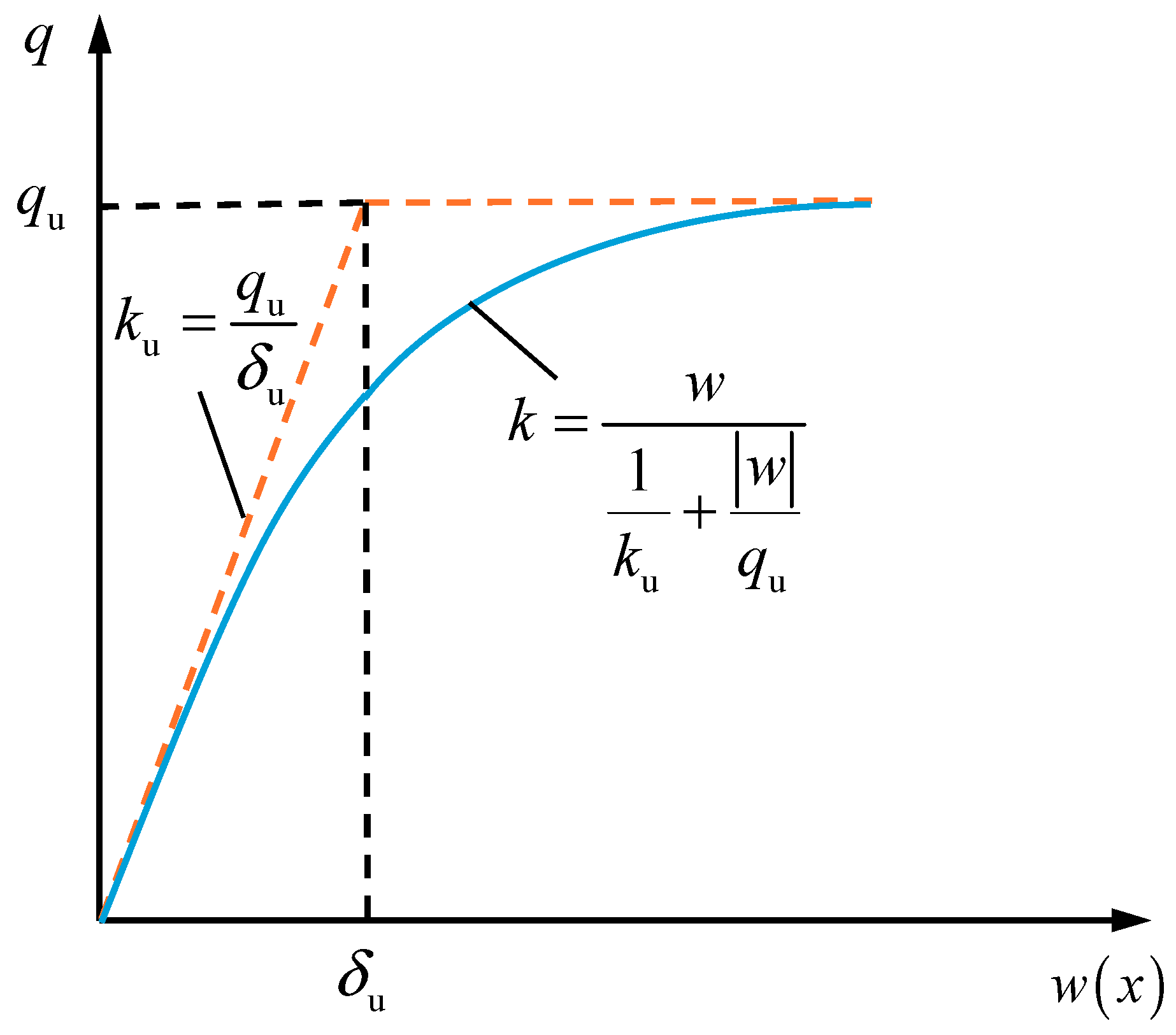
2.1. Nonlinear Pasternak Foundation Model

In order to capture the effect of the nonlinear behavior of surrounding soils, Liang et al. [24], Kang et al. [26], and Ke et al. [29] introduced the nonlinear Pasternak foundation model to investigate the mechanical response of existing tunnels caused by a new overcrossing tunnel, foundation pit excavation, and surface loading, respectively. Their studies indicated that the nonlinear behavior of surrounding soils has a noticeable influence on the response of the existing tunnel, especially in the case that the induced soil deformation and additional stresses are relatively large, and the nonlinear Pasternak foundation model is feasible to characterize the nonlinear behavior of surrounding soils. This model is composed of a shear layer and a nonlinear spring that is described by a hyperbolic function, so the correlation between the reaction force and the associated displacement may be articulated as follows:
q ( x ) = w ( x ) 1 k u + | w ( x ) | q u G t d 2 w ( x ) d x 2
where q ( x ) is the reaction force given by surrounding soils at the position x (kPa); w ( x ) is the corresponding displacement of surrounding soils occurring at the position x (m); k u and q u represent the initial reaction coefficient (kN/m3) and ultimate resistance of surrounding soils (kPa), respectively; δ u = q u / k u denote the displacement of surrounding soils that its reaction force linearly increases to ultimate resistance (m); Gt is the stiffness of the shear layer (kN/m), and it is given by G t = E s H t / [ 6 ( 1 + v ) ] ; H t is the thickness of the shear layer (m), and it can be taken as 2.5 times the diameter of the existing tunnel; and Es and v are the elastic modulus (kPa) and Poisson ratio of surrounding soils, respectively. The ultimate resistance of surrounding soils can be calculated using the following typical expression [30]:
q u = γ h N q D + 1 2 γ D 2 N γ
where D is the outer diameter of the existing tunnel (m); γ is the unit weight of surrounding soils (kN/m3); h is the burial depth of the existing tunnel (m); and Nq and N γ are two resistance factors of surrounding soils, and they can be evaluated using the following expressions:
N q = ( ϕ H 44 D ) exp ( π tan ψ ) tan 2 ( 45 + ϕ 2 )
N γ = exp ( 0.18 ϕ 2.5 )
Figure 1 illustrates the association between the reaction force and the respective displacement within the nonlinear Pasternak foundation model, and it shows that as the displacement of surrounding soils increases, the reaction force increases nonlinearly and gradually approaches the ultimate resistance of surrounding soils. The reaction coefficient takes the largest value at the zero-displacement (i.e., initial reaction coefficient), while it decreases gradually and finally approaches zero as the displacement of surrounding soils increases. Thus, this model is available to characterize the nonlinear attenuation of the reaction coefficient and the finite ultimate resistance for the surrounding soils.

2.2. Additional Stresses Induced by a New Under-Crossing Shield Tunnel

Figure 2 represents the mechanical analysis model for an existing tunnel with a new under-crossing shield tunnel. The full sequence of the under-crossing procedure for the newly constructed shield tunnel is typically categorized into the following three distinct stages:
(i)
Stage I, the initiation of the new shield tunnel construction occurs, resulting in the excavation face being positioned at a considerable distance from the existing tunnel. The distance from the excavation face to the intersection point with the existing tunnel is represented as a negative value, i.e., b < 0;
(ii)
Stage II, as the new shield tunnel is continued to excavate, its excavation face gradually approaches the intersection point with the existing tunnel, i.e., b = 0;
(iii)
Stage III, the new tunnel under-crosses the existing tunnel, and its excavation face gradually advances away from the intersection point with the existing tunnel, i.e., b > 0.
During these three stages, the tunnel shield machine advances continuously, and it generates noticeable construction loads on the surrounding soils and induces soil loss. These effects further result in the additional stresses and deformation of the surrounding soils, which are subsequently transmitted to the existing tunnel.
(i) Additional stresses induced by construction loads
The construction loads given by a tunnel shield machine mainly include additional thrust, friction force, and grouting pressure. In general, the existing tunnel primarily generates vertical displacement during the under-crossing process of a new shield tunnel, so this study only considers the effects of the vertical additional stresses. For a simplification without losing generality, the additional thrust pt is assumed to be uniform loading that is distributed in the excavation face, the friction force pf is treated as a uniform loading that is distributed along the sidewall, and the grouting pressure pg of the shield tail is considered to be a uniform loading that is distributed radially. Based on these simplifications, the additional stresses at any position (x, y, z) induced by the construction loads of a new shield tunnel can be directly computed using the typical Mindlin solution, as follows [31]:
σ t = 0 R s 0 2 π p t r y 8 π G t ( 1 v ) { ( 1 2 v ) R 1 3 ( 1 2 v ) R 2 3 3 ( h z 0 + r sin θ ) 2 R 1 5 3 ( 3 4 v ) ( h + z 0 r sin θ ) 2 R 2 5 + 6 ( z 0 r sin θ ) R 2 5 [ z 0 r sin θ + ( 1 2 v ) ( h + z 0 r sin θ ) 2 + 5 h ( h + z 0 r sin θ ) 2 R 2 2 ] } d r d θ
σ f = 0 L 0 2 π p f s ( y s ) 8 π ( 1 v ) { ( 1 2 v ) R 3 3 ( 1 2 v ) R 4 3 3 ( h z 0 + R s sin θ ) 2 R 3 5 + 6 ( z 0 R s sin θ ) R 4 5 [ z 0 R s sin θ + ( 1 2 v ) ( h + z 0 R s sin θ ) 2 + 5 h ( h + z 0 R s sin θ ) 2 R 4 2 ] } d s d θ
σ g = 0 m 0 2 π p g R s sin θ 8 π ( 1 v ) { ( 1 2 v ) ( h z 0 + R s sin θ ) R 5 3 + ( 1 2 v ) ( h z 0 + R s sin θ ) R 6 3 3 ( h z 0 + R s sin θ ) 3 R 5 5 3 ( 3 4 v ) h ( h + z 0 R s sin θ ) 2 R 6 5 3 ( z 0 R s sin θ ) ( h + z 0 R s sin θ ) ( 5 h z 0 + R s sin θ ) R 6 5 + 30 ( z 0 R s sin θ ) h ( h + z 0 R s sin θ ) 3 R 6 7 } d s d θ
with
R 1 , 2 = ( x r cos θ ) 2 + y 2 + ( h z 0 ± r sin θ ) 2
R 3 , 4 = ( x R s cos θ ) 2 + ( y s ) 2 + ( h z 0 ± R s sin θ ) 2
R 5 , 6 = ( y L s ) 2 + ( x R s cos θ ) 2 + ( h z 0 ± R s sin θ ) 2
where σt, σf, and σg represent the additional stresses induced by additional thrust, friction force, and grouting pressure, respectively (kPa); x is the horizontal coordinate along the existing tunnel (m); y is the longitudinal coordinate that is perpendicular to x (m); z is the vertical coordinate (m); h is the vertical coordinate of the calculation points, taken as the burial depth of the existing tunnel; z 0 is the depth of the new under-crossing shield tunnel (m); and θ is the intersection angle between the existing tunnel and the new under-crossing shield tunnel.
(ii) Additional stress induced by soil loss
As voids generally appear during the excavation process of a new under-crossing shield tunnel, the surrounding soils would deform to fill them and further result in noticeable additional stresses on the existing tunnels, which can be simply evaluated according to the Loganathan and Poulos solution [32], as follows:
σ z = 2.6 E s ω D ( 1 + v ) E s D 4 ( E I ) eq 12 V l oss π z 0 y 2 + ( h z 0 ) 2 × ( 1 x x 2 + y 2 + ( h z 0 ) 2 ) exp [ 1.38 y 2 ( h z 0 R s ) 2 ]
where V loss is the loss rate of surrounding soils; ω is the depth-influencing coefficient of the existing tunnel, which can be given by ω = 1 + 1 / ( 1.7 h / D ) ; R s is the radius of the new under-crossing tunnel (m); and ( E I ) eq is the equivalent bending stiffness of the existing tunnel (N∙m2). Shiba et al. [33] presented analytical formulas aimed at estimating equivalent longitudinal bending stiffness. The formulations can be expressed as follows:
( E I ) eq = cos 3 ψ cos ψ + ( ψ + π 2 ) sin φ E c I c
ψ + cot ψ = π ( 0.5 + N k b l s E c A c )
k b = E b A b / l b
where kb is the elastic stiffness of the longitudinal joints, E b is the Young’s modulus of the bolts, A b is the cross-sectional area of the bolts, l b is the length of the bolts, N is the number of longitudinal bolts, φ is the deformation angle of the bolt, l s is the width of the tunnel segments, E c is the Young’s modulus of the tunnel segments, ψ is the angle of the neutral axis, I c is the longitudinal moment of inertia of the segment’s cross-section, and A c is the cross-sectional area of the tunnel segments.
Therefore, to capture the effects of the construction loads and the soil loss of a new under-crossing shield tunnel, the induced additional stresses along the axis of the existing tunnel can be expressed as the following summation form:
σ ( x ) = σ t + σ f + σ g + σ z

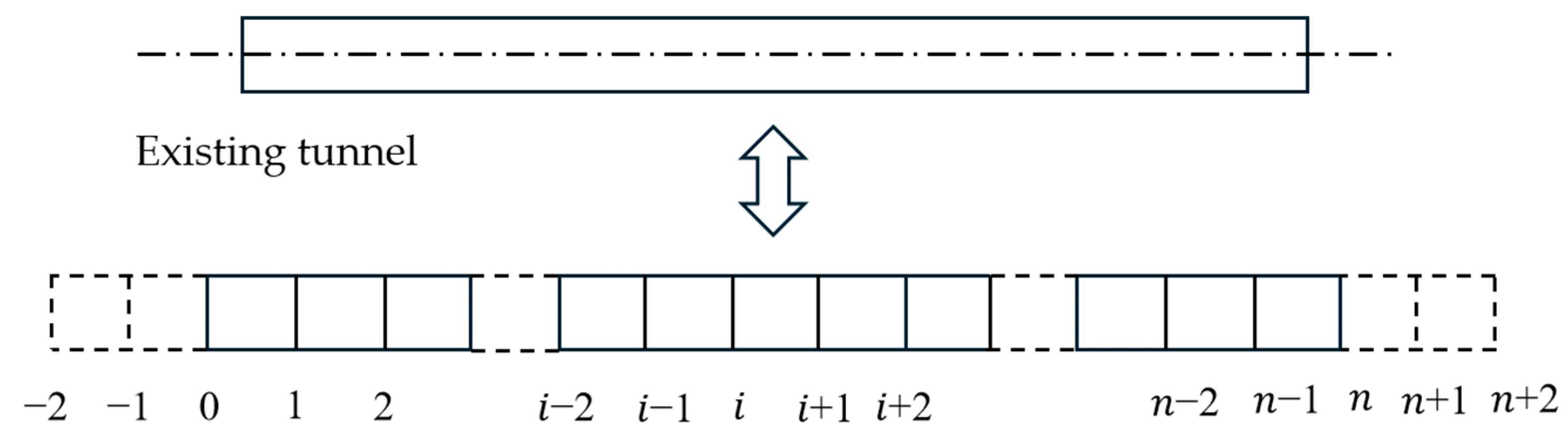
2.3. Governing Differential Equation of Existing Tunnel

As illustrated in Figure 3, it is postulated that the existing tunnel is supported by a nonlinear Pasternak foundation, with its mechanical behavior conforming to the principles of the Euler–Bernoulli beam theory. Utilizing force equilibrium. Based on the force equilibrium, Euler–Bernoulli beam theory, and constitutive relationship of the nonlinear Pasternak foundation model, the governing differential equation of the existing tunnel can be derived as follows [24]:
( E I ) eq d 4 w ( x ) d x 4 + w ( x ) 1 k u + | w ( x ) | q u D G t D d 2 w ( x ) d x 2 = p ( x )
where w ( x ) is the vertical displacement of the existing tunnel and p ( x ) is the additional loading acting along the longitudinal axis of the existing tunnel, which is induced by the new under-crossing shield tunnel and can be calculated using Equation (9) as follows: p ( x ) = σ ( x ) D .
In addition, assuming the new under-crossing shield tunnel is constructed at the position far from the two ends (i.e., stations) of the existing tunnel, the boundary conditions at the two ends of the existing tunnel can be considered as free, that is, the bending moment and shear force at these two ends are zero
M | x = 0 = ( E I ) eq d 2 w d x 2 | x = 0 = 0
Q | x = 0 = ( E I ) eq d 3 w d x 3 | x = 0 = 0

3. Theoretical Solution and Calculation Method

The governing Equation (10) constitutes a fourth-order inhomogeneous differential equation featuring nonlinear terms, so it is generally impossible to derive an analytical solution. In this study, the theoretical solution and calculation method are developed using the finite difference formula and the Newton iteration method. As depicted in Figure 4, the existing tunnel spans a length of L along its longitudinal axis and is divided into n + 1 segments. The lengths of each element are specified as follows: l = L / n . Moreover, four additional virtual nodes are incorporated at both extremities of the existing tunnel (i.e., −2, −1, n + 1, n + 2).
Based on the discretization scheme above, the second- and fourth-order derivatives of the vertical displacement w(x) can be approximated using the central finite difference formula as follows:
{ d 2 w d x 2 = w i + 1 2 w i + w i 1 2 l 2 d 4 w d x 4 = w i + 2 4 w i + 1 + 6 w i 4 w i 1 + w i 2 l 4
Substituting Equation (13) into Equation (10) leads to the following:
( E I ) eq w i + 2 4 w i + 1 + 6 w i 4 w i 1 + w i 2 l 4 + w i D 1 k u + | w i | q u G t D w i + 1 2 w i + w i 1 2 l 2 = p i
Similarly, using the discretization scheme above, boundary conditions (11) and (12) can be approximated using the central finite difference formula as follows:
{ M 0 = ( E I ) eq w 1 2 w 0 + w 1 l 2 = 0 M n = ( E I ) eq w n + 1 2 w n + w n 1 l 2 = 0
{ Q 0 = ( E I ) eq w 2 2 w 1 + 2 w 1 w 2 2 l 3 = 0 Q n = ( E I ) eq w n + 2 2 w n + 1 + 2 w n 1 w n 2 2 l 3 = 0
From Equations (15) and (16), the displacements of four virtual nodes can be directly obtained as follows:
{ w 2 = 4 w 0 4 w 1 + w 2 w 1 = 2 w 0 w 1 w n + 2 = 4 w n 4 w n - 1 + w n - 2 w n + 1 = 2 w n w n - 1 + w n - 2
Using Equation (17), Equation (15) can degenerate into n + 1 algebraic equations with respect to n + 1 unknown displacements (i.e., w 0 ,   w 1 ,   ,   w n ), thus it can be directly rewritten as a vector-matrix form, as follows:
K t w + w D 1 k u + | w | q u G w = p
where w is the vertical displacement vector of the existing tunnel, p is the additional loading vector acting on the existing tunnel during the under-crossing process of a new shield tunnel, K t is the structural stiffness matrix of the existing tunnel, and G is the shear stiffness matrix of the surrounding soils. These vectors and matrices are obtained as follows:
w = { w 0 , w 1 , , w n 1 , w n } T
p = { p 0 , p 1 , , p n 1 , p n } T D
K t = ( E I ) eq l 4 [ 2 4 2 0 2 5 4 1 1 4 6 4 1 1 4 6 4 1 2 5 4 1 0 2 4 2 ] ( n + 1 ) × ( n + 1 )
G = G t D l 2 [ 0 0 0 0 1 2 1 1 2 1 1 2 1 1 2 1 0 0 0 0 ] ( n + 1 ) × ( n + 1 )
Equation (18) is a nonlinear algebraic system that can be solved using the typical Newton iteration method. Let
F ( w ) = K t w + w 1 k u + | w | q u D G w p
Without the loss of generality, assuming the Jacobian matrix of F(w) exists, it can be derived as follows:
F ( w ) = K t + K s G
where K s is the Jacobian matrix of the corresponding nonlinear term in Equation (23), which can be obtained as follows:
K s = [ f 0 0 f 1 f i f n 1 0 f n ] ( n + 1 ) × ( n + 1 )
with
f i = 1 1 k u + | w i | q u D w i q u ( 1 k u + | w i | q u ) 2 D , i = 0 , 1 , , n
According to the typical Newton iteration method, the iteration formula for the vertical displacement vector ( w ) of the existing tunnel can be obtained as follows:
w ( k + 1 ) = w ( k ) [ F ( w ( k ) ) ] 1 F ( w ( k ) )
where [ F ( w ) ] 1 is the inverse-matrix of F ( w ) , k is the iterating order, and w ( k ) and w ( k + 1 ) are the vertical displacement vectors of the existing tunnel at the iterating orders of k and k + 1 , respectively.
Let Δ w ( k ) = w ( k + 1 ) w ( k ) , which can be derived from Equation (27) as follows:
Δ w ( k ) = F ( w ( k ) ) 1 F ( w ( k ) )
w ( k + 1 ) = w ( k ) + Δ w ( k )
From Equations (28) and (29), the vertical displacement vector (w) of the existing tunnel can be obtained using the iterative calculation as follows: (i) giving an initial value of w ( 0 ) and substituting it into Equation (28) to compute the value of Δ w ( 1 ) ; (ii) using Equation (29) to calculate the value of w ( 1 ) and substituting it into Equation (28) to compute the value of Δ w ( 1 ) ; (iii) repeating step (ii) until the iterative tolerance is small enough, i.e., | Δ w ( k ) | < 10 6   m ; and (iv) the last calculation result of w ( k + 1 ) can be set as the value of w , i.e., the vertical displacement vector of the existing tunnel. Then, the corresponding bending moment and shear force of the existing tunnel can be calculated from the results of the vertical displacement using the discretization scheme above and the central finite difference formula, which are similar to those in Equations (15) and (16).

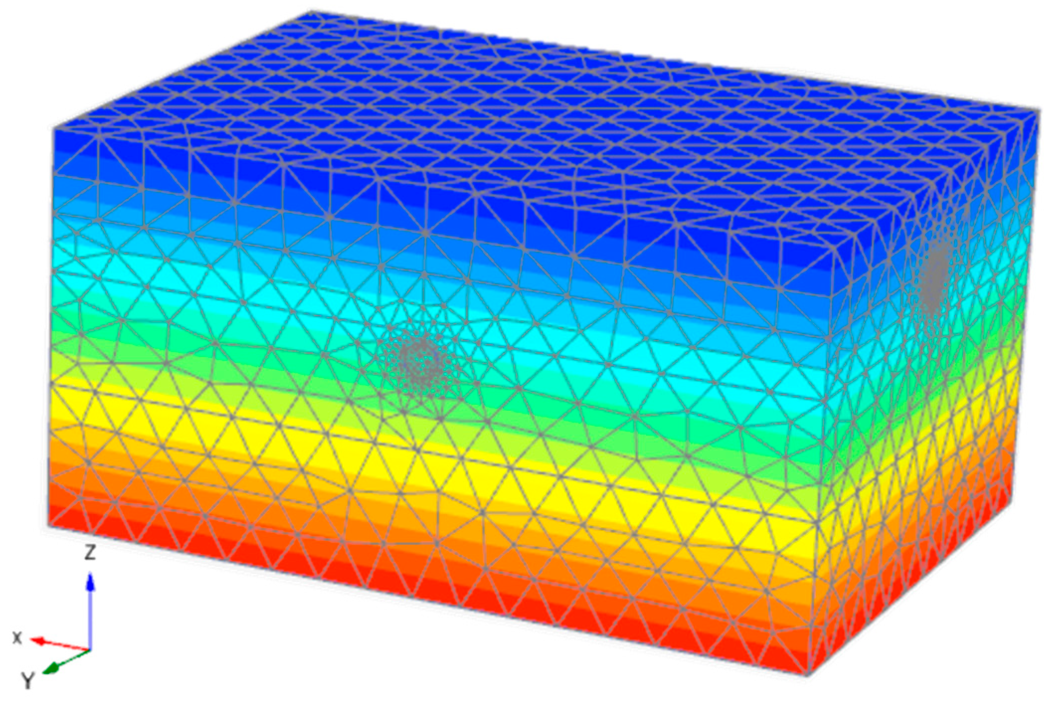
4. Case Study and Validation

To demonstrate the mechanical response of the existing tunnel affected by the construction of a new under-crossing shield tunnel, this section presents a typical case study from the Wuhan Metro project. The Line 4 project of the Wuhan Metro was constructed by under-crossing the existing tunnels of Line 2 perpendicularly, and to ensure the safety of Line 2 during the under-crossing process of Line 4, field monitoring was conducted [34]. The physical attributes of the surrounding soils are presented in Table 1. The existing tunnel on Line 2 has an outer diameter of 6.2 m and a thickness of 0.3 m and is situated at a depth of 18 m. In contrast, the excavation diameter for the new tunnel on Line 4 is also 6.2 m, while its depth reaches 30 m. The shield tunneling machine spans a length of 7.5 m. According to the engineering data and the research results of Wu et al. [34], the loss rate of the surrounding soils is set as 0.28%; the initial reaction coefficient and ultimate resistance of the surrounding soils are taken as 1.2 × 10⁴ kN/m3 and 100 kPa, respectively; the equivalent bending stiffness of the existing tunnel is obtained as 5.75 × 10¹⁰ N∙m2; and the additional thrust, friction force, and grouting pressure are taken as 295 kPa, 180 kPa and 236 kPa, respectively.
For the sake of validating the reliability of the developed solution and investigating the under-crossing process associated with the shield tunnel on Line 4, a series of three-dimensional finite element simulations were conducted, as depicted in Figure 5. In this numerical framework, the x-direction is aligned with the longitudinal axis of the existing tunnel, and its dimensions are taken as 140 m × 100 m × 70 m, which are divided into 96,805 elements with 152,972 nodes. The typical Mohr–Coulomb yield criterion is adopted to characterize the behaviors of surrounding soils. The existing tunnel is modeled as an elastic beam, and it is divided into 140 elements along the longitudinal direction for calculating the mechanical response. The lateral and bottom boundaries of the model are fixed in their normal directions, whereas the top surface is allowed to remain free. The under-crossing of the new shield tunnel is achieved by incrementally adjusting the distance between the tunneling face and the intersection point with the existing tunnel.
Utilizing the three-dimensional finite element simulations alongside calculations from the developed solution, Figure 6 illustrates the vertical displacement distributions of the existing tunnel during three distinct phases of the under-crossing process, i.e., b = −10 m, b = 0 m, and b = 10 m. As a comparison, the computed results from the linear Pasternak foundation model are also given in this figure. The results indicate that the vertical displacement of the existing tunnel progressively increases as the tunneling face of the under-crossing tunnel proceeds. At the beginning stage (i.e., b = −10 m), the tunneling face of the under-crossing tunnel is relatively far from the existing tunnel, and at the position of the existing tunnel, the induced additional stresses are very small; thus, the vertical displacement of the existing tunnel is slight. At this stage, the calculated values from the nonlinear Pasternak foundation model are solidly in agreement with those from the linear foundation model. This is because, for a relatively small displacement, the surrounding soils exhibit a linear mechanical behavior, as shown in Figure 1; thus, the resistance difference of these two foundation models at the same displacement is insignificant. As the under-crossing shield tunnel advances, its excavation face gradually approaches the intersection point with the existing tunnel (i.e., b = 0 m), which makes the induced additional stresses on the existing tunnel become relatively large. As a result, the vertical displacement of the existing tunnel becomes markedly evident. At this stage, the difference between the results of the two foundation models is evident. The vertical displacement calculated using the nonlinear model surpasses that determined via the linear model, demonstrating a closer alignment with the outcomes of the three-dimensional finite element simulations. After the new shield tunnel under-crossing (i.e., b = 10 m), the vertical displacement continues to increase, and the calculated difference between these two foundation models turns out to be greater. The phenomenon occurs because, for a relatively large displacement, the nonlinear behavior of the surrounding soils turns out to be obvious, as shown in Figure 1. In this scenario, the linear foundation model presents a much larger resistance than the nonlinear model for the same displacement. When contrasted with the linear foundation model, the nonlinear foundation model offers a more accurate prediction of the vertical displacement of the existing tunnel across all stages of the under-crossing process. Specifically, when the vertical displacement of the existing tunnel caused by the shield is substantial, the nonlinear model demonstrates enhanced accuracy in predicting tunnel displacement due to its ability to account for complex soil behavior under higher stress conditions. Conversely, in cases in which the displacement is small, both models yield comparable results with satisfactory accuracy.
Figure 7 depicts the changes in the tensile stress increment of the existing tunnel throughout the tunneling process of the under-crossing tunnel. Strain gauges were employed in the field to quantify the tensile stress. These gauges are affixed to the existing tunnel, with the obtained strain data subsequently converted into tensile stress through the application of Hooke’s Law, which describes the relationship between stress and strain in elastic materials. As a comparison, the field monitoring data given by Wu et al. [34] is also plotted in this figure. The monitoring point is positioned at the bottom arch of the existing tunnel, specifically at the intersection of the existing and under-crossing tunnels. Observations reveal that as the excavation face of the under-crossing tunnel progresses, the tensile stress increment of the existing tunnel begins at a minimal level, increases gradually, and ultimately stabilizes at a certain value. However, in the final stages, the field monitoring data still exhibited a slow increase, which differs from the finite element monitoring results and the theoretical method presented in this paper. We consider that this discrepancy may be influenced by dynamic site factors such as groundwater levels and changes in the speed of the shield tunneling. Being the same as Figure 6, at the beginning stage of the tunnel under-crossing process, the induced tensile stress increment of the existing tunnel is relatively small, and the calculated values from both the linear and nonlinear foundation models exhibit strong consistency with one another. Additionally, these values align well with the measured data and the results from numerical simulations, whereas, at the later stage, the induced tensile stress increment of the existing tunnel becomes great, the calculation values of these two foundation models have significant differences, and the results of the nonlinear model match better with the field monitoring data and numerical simulating values. These findings indicate that the linear foundation model generally predicts the behavior of the surrounding soils and the mechanical response at the beginning stage of the tunnel under-crossing process while overestimating the resistance of surrounding soils and underestimating the mechanical response at the later stage. In contrast, the nonlinear foundation model can characterize the behavior of the surrounding soils effectively and further predict the mechanical response more reliably for the whole tunneling process of a new under-crossing tunnel.

5. Parameter Studies

In the previous section, the reliability of the developed solution and its calculation method has been validated through a comparison with the numerical simulations and field monitoring data. This section further performs a series of computations to illustrate the effects from the ultimate resistance and reaction coefficient of the surrounding soils and those from the vertical distance and intersection angle between existing and under-crossing tunnels.

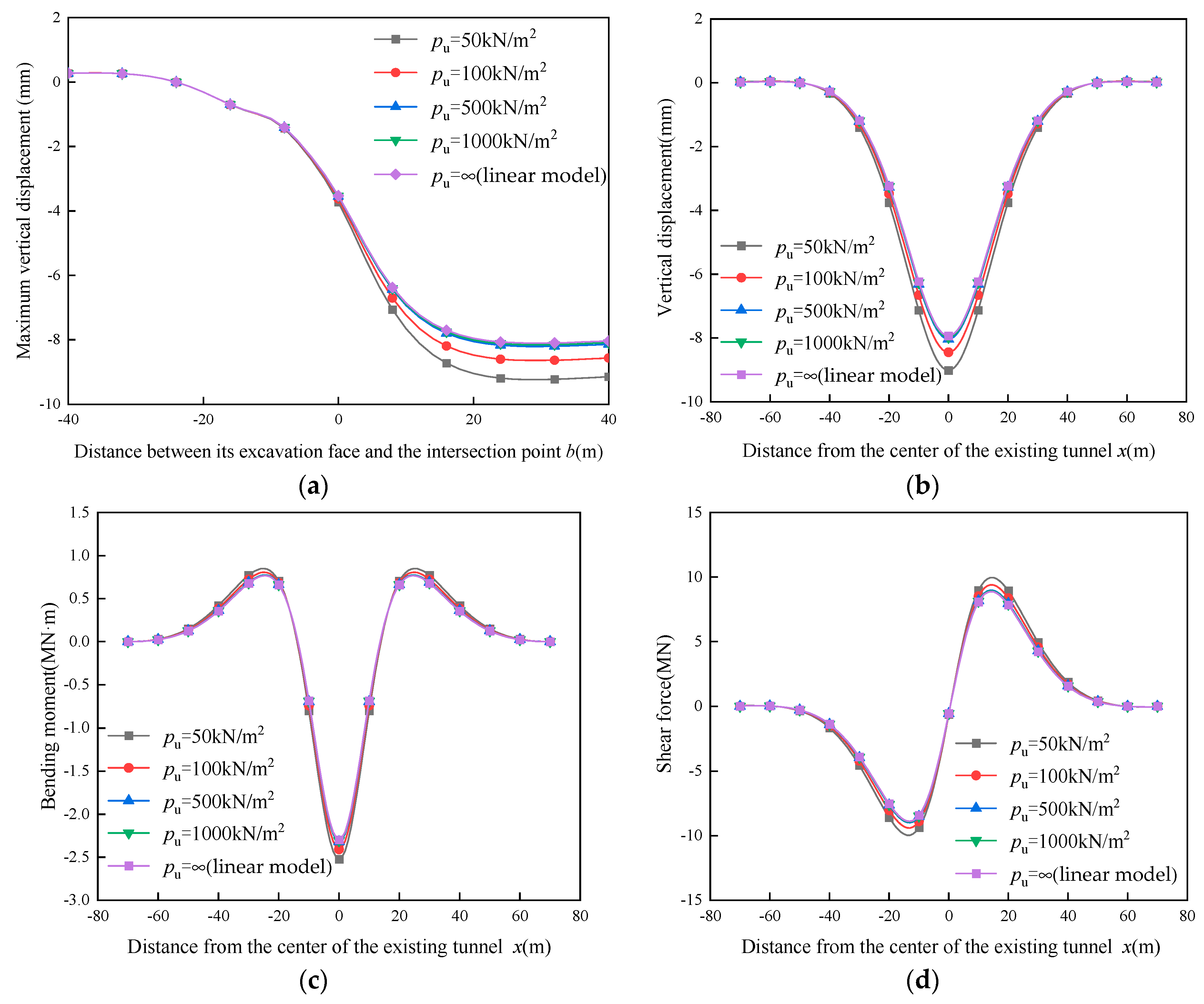
5.1. Influence of the Ultimate Resistance of Surrounding Soils

Figure 8 illustrates the mechanical responses induced by the under-crossing tunnel for the surrounding soils with different ultimate resistances. As observed in Figure 8a,b, with the increase in ultimate resistance of surrounding soils, the vertical displacement decreases gradually. At the beginning stage (i.e., b < 0), the tunneling face of the under-crossing tunnel does not approach the intersecting point of these two tunnels, and the influence of the ultimate resistance of the surrounding soils is slight, while, at the later stage (i.e., b ≥ 0), this influence turns out to be significant by degrees. For an ultimate resistance of 50 kN/m2, the maximum vertical displacement given by the nonlinear Pasternak foundation model is 9 mm, while that given by the linear foundation model is 8 mm; when the ultimate resistance increases to 1000 kN/m2, the vertical displacement curves given by both the nonlinear and linear foundation models seem to be coincident with each other. Figure 8c,d illustrate the distributions of the bending moment and shear force of the existing tunnel, respectively. Notably, the bending moment distribution exhibits an “M” shape, while its shear force distribution is a lying “S” shape, and their absolute values take the maximum at the positions of about ±20 m. Similar to Figure 8a,b, both the bending moment and shear force of the existing tunnel gradually increase as the ultimate resistance rises. When the ultimate resistance increases to 1000 kN/m2, the changes in the ultimate resistance show an insignificant effect on the mechanical responses. For the situation, the calculation results of the nonlinear Pasternak foundation model approach those of the linear foundation model. These findings indicate that enlarging the ultimate resistance of surrounding soils is beneficial to reducing the mechanical response of the existing tunnel, especially for the later tunneling stage of an under-crossing tunnel.

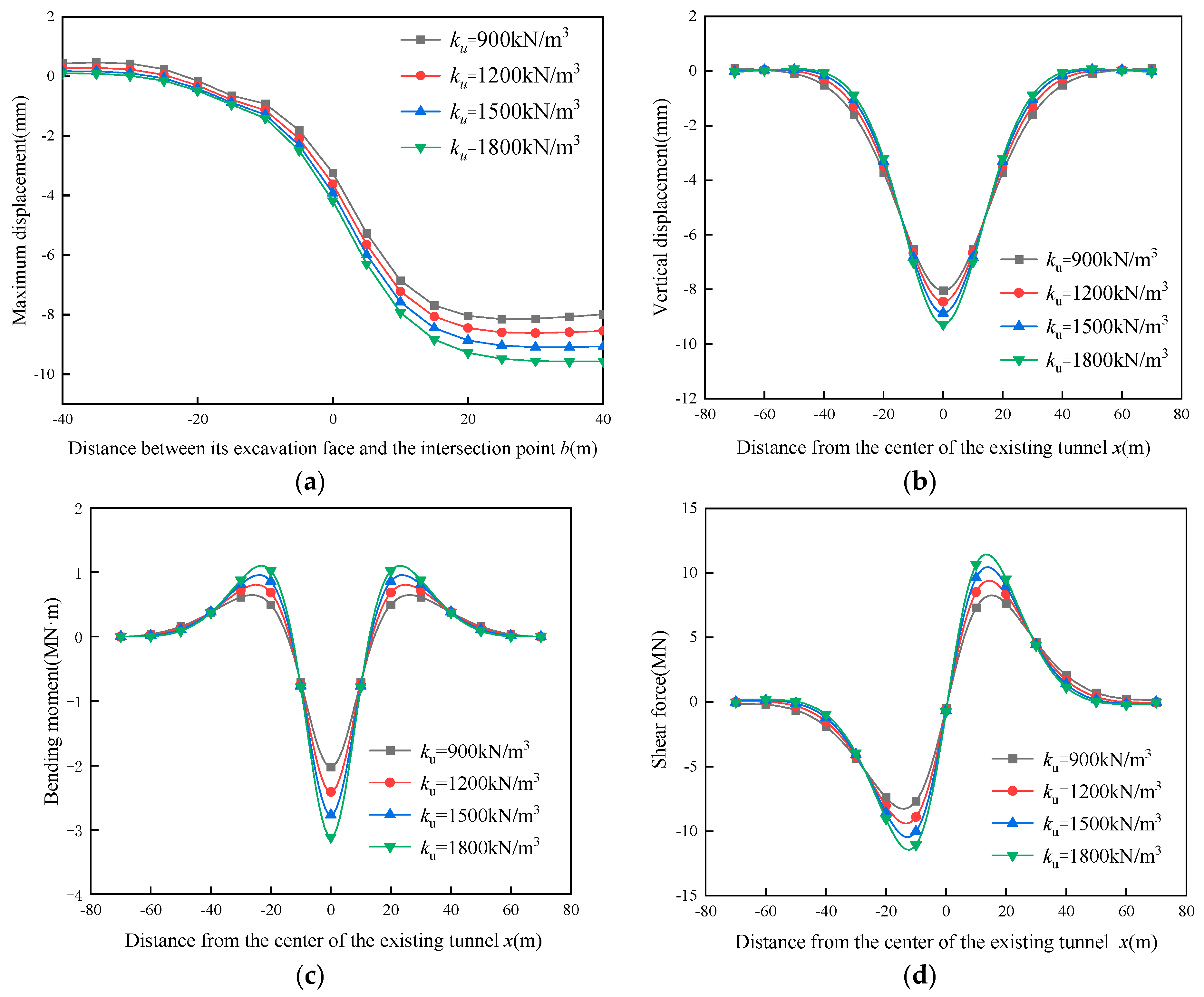
5.2. Influence of the Reaction Coefficient of Surrounding Soils

Figure 9 depicts the effects of the reaction coefficient of surrounding soils on the mechanical responses during the under-crossing process of a new shield tunnel. In these computations, the ultimate resistance of surrounding soils is given as 1000 kN/m2, and its initial reaction coefficient is taken from 900 kN/m3 to 1800 kN/m3. It is observed that the mechanical responses of the existing tunnel—such as vertical displacement, bending moment, and shear force—become increasingly significant with the rise in the initial reaction coefficient of the surrounding soils. Figure 9a indicates that the influence of the initial reaction coefficient of surrounding soils is relatively small at the beginning stage of under-crossing tunnel construction (i.e., b < 0), while it turns out to be greater at the later stage after the under-crossing tunnel passes through (i.e., b ≥ 0). As the initial reaction coefficient of surrounding soils increases from 900 kN/m3 to 1800 kN/m3, the maximum vertical displacement of the existing tunnel rises from 8 mm to 9.2 mm. As illustrated in Figure 9b–d, the vertical displacement and negative bending moment of the existing tunnel reach their peak values at the intersection of the existing and under-crossing tunnels. In contrast, the positive bending moment and shear force approach their maximum values on both sides of this intersection position at a certain distance. With an increase in the initial reaction coefficient, all distribution curves for vertical displacement, bending moment, and shear force progressively converge toward the intersection point of the two tunnels. This indicates that the primary area affected by the construction of the under-crossing tunnel becomes narrower. This phenomenon happens because the surrounding soils with larger reaction coefficients are stiffer, and the stiffness ratio between the surrounding soils and the existing tunnel is greater, which causes the existing tunnel to deform together with the surrounding soils more significantly and also makes it deform narrowly toward that of the surrounding soils.

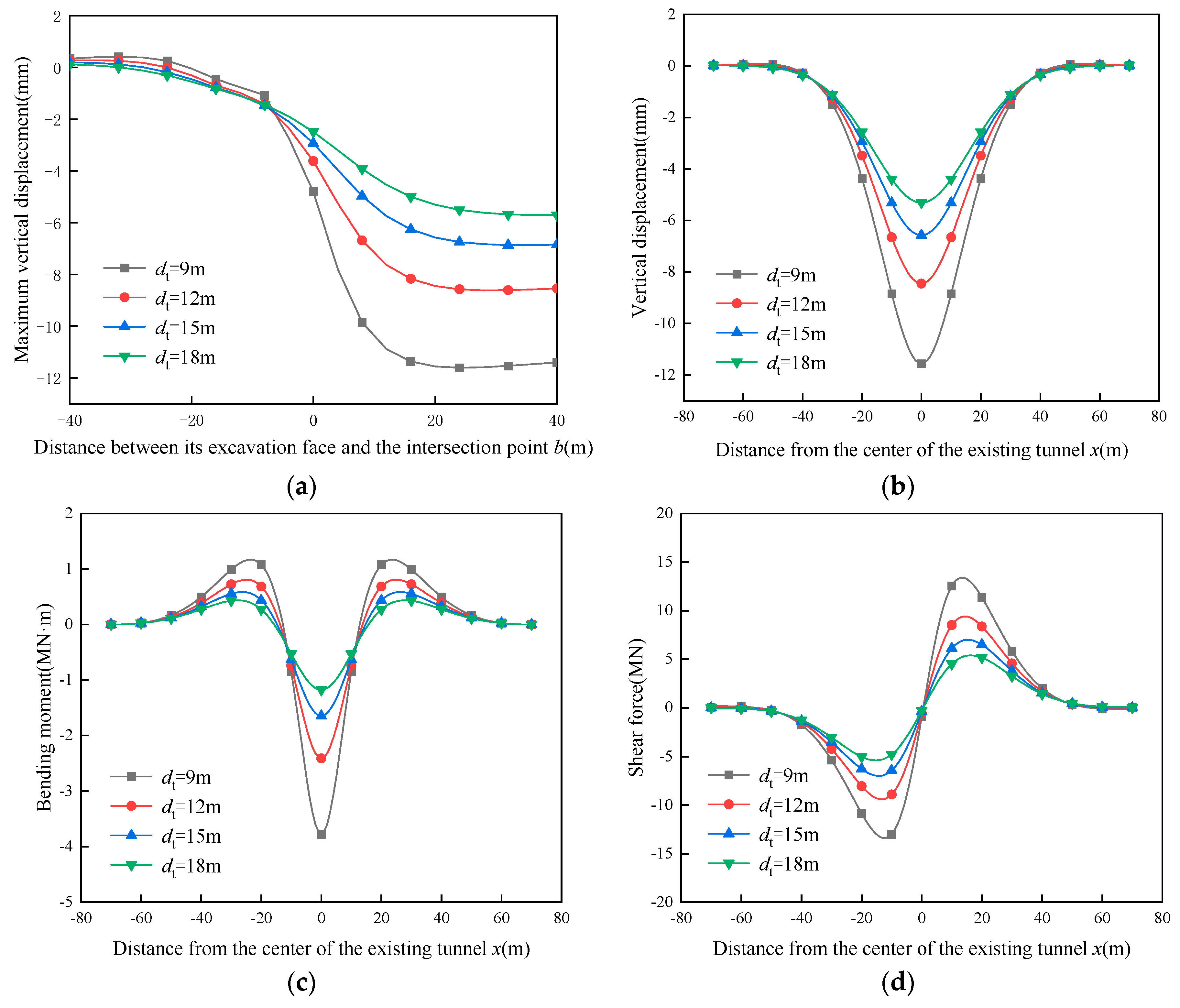
5.3. Influence of the Vertical Distance between Existing and Under-Crossing Tunnels

Figure 10 depicts the mechanical responses of the existing tunnel induced by the under-crossing tunnel at various vertical distances. In this figure, dt represents the net vertical distance between the two tunnels. It is clearly evident that the net vertical distance significantly impacts the vertical displacement, bending moment, and shear force of the existing tunnel throughout the entire construction process of the under-crossing tunnel. As the net vertical distance increases, these mechanical responses gradually become smaller. This phenomenon occurs because the increase in the net vertical distance lengthens the transmission paths of additional stresses induced by the construction of the under-crossing tunnel, which can mitigate the additional stresses acting on the existing tunnel effectively. Similar to Figure 9a, it can be clearly seen from Figure 10a that the impact of the net vertical distance between these two tunnels is slight in the case that the tunneling face of the under-crossing tunnel is relatively far from the existing tunnel (i.e., b < −8 m) before approaching their intersection point, whereas it gradually becomes more noticeable for the cases in which the tunneling face of the under-crossing tunnel becomes close to the intersection point and passes through (i.e., b ≥ −8 m). As seen in Figure 10b–d, in the situation in which the deformation of the existing tunnel is relatively stable (i.e., b = 20 m), the maximum values of vertical displacement, negative bending moment, and shear force for the existing tunnel decrease from 11.5 mm, 3.8 MN·m, and 13.4 MN to 5.3 mm, 1.2 MN·m, and 5.4 MN, respectively, as the net vertical distance between these two tunnels increases from 9.0 m to 18.0 m. This indicates that increasing the vertical distance of under-crossing and existing tunnels can control the mechanical response of existing tunnels effectively.

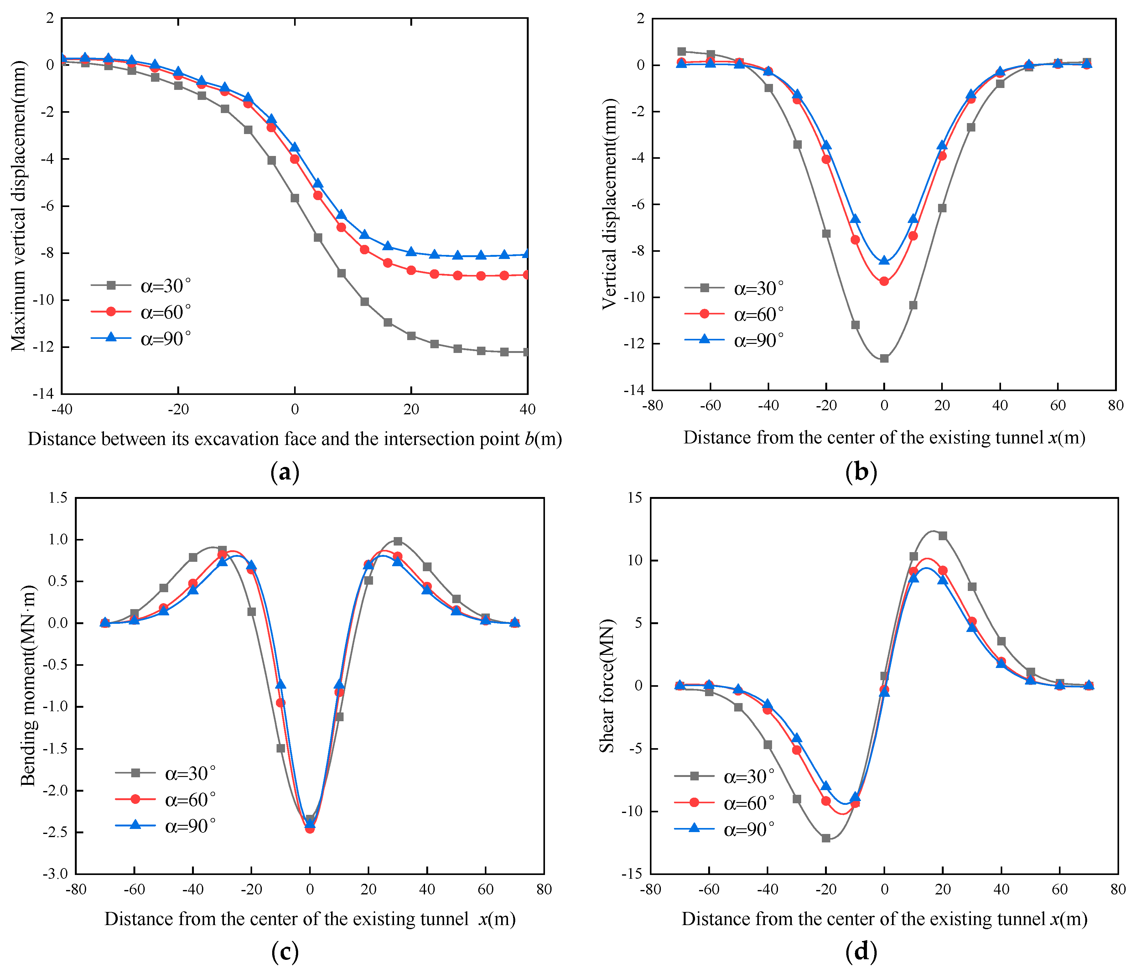
5.4. Influence of the Intersection Angle between Existing and Under-Crossing Tunnels

Figure 11 illustrates the mechanical responses of the existing tunnel caused by the under-crossing tunnel at various intersection angles. In the calculations, the intersection angles are taken as 30°, 60°, and 90°. As seen, the intersection angle also shows remarkable effects on the vertical displacement, bending moment, and shear force of the existing tunnel, especially for the later stage of under-crossing tunnel construction (i.e., b ≥ 0), as shown in Figure 11a. A larger intersection angle generally leads to a significant reduction in the maximum values of the vertical displacement, bending moment, and shear force of the existing tunnel. As the intersection angle increases from 30° to 90°, the maximum vertical displacement of the existing tunnel decreases from 12.6 mm to 8.1 mm. Furthermore, as the intersection angle increases, the distribution curves for the vertical displacement, bending moment, and shear force progressively narrow, as illustrated in Figure 11b–d, which indicates that the main influencing region of the under-crossing tunnel decreases. This phenomenon occurs because as the intersection angle increases, the longitudinal axis of the under-crossing tunnel departs from that of the existing tunnel gradually, and further, their distance increases gradually, which reduces the additional stresses acting on the existing tunnel by degrees. Thus, increasing the intersection angle is an effective measure to control the mechanical response of the existing tunnel induced by an under-crossing tunnel. For practical engineering, a new shield tunnel is advisable to under-cross an existing one using a large intersection angle.

6. Conclusions

Through incorporating the nonlinear behavior of surrounding soils and the construction effects of under-crossing the shield tunnel simultaneously, this study develops a novel theoretical solution and calculation method from the nonlinear Pasternak foundation and Euler–Bernoulli beam models for predicting the mechanical response of the existing tunnel. The additional stresses resulting from the construction loadings during the tunnel under-crossing process are evaluated using the Mindlin solution, while those from the soil loss are calculated using the Loganathan and Poulos solution. The finite difference formula and Newton iteration method are employed to solve the governing differential equation of the existing tunnel and, further, to develop the corresponding calculation method. One case study is conducted to demonstrate the mechanical response characteristics of an existing tunnel undergoing the construction process of an under-crossing shield tunnel and to verify the validity of the proposed solution. In addition, the effects of the ultimate resistance and reaction coefficient of surrounding soils and those of the vertical distance and intersection angle between these two tunnels are illustrated and discussed. The main conclusions are as follows:
(a) The vertical displacement of the existing tunnel increases gradually with the continuous construction of the under-crossing tunnel. At the beginning stage, in which the under-crossing tunnel is far away from the existing tunnel, the induced vertical displacement is very small, and the nonlinear behavior of surrounding soils is slight, so both the linear and nonlinear foundation models are feasible. However, at the later stage, which induces a relatively large deformation, the nonlinear behavior of the surrounding soils generally plays a significant role, so the linear foundation model commonly overestimates the resistance of surrounding soils and underestimates the mechanical response of the existing tunnel. In contrast, the nonlinear foundation model can characterize the behavior of surrounding soils effectively and predict the mechanical response of existing tunnels more reliably for the whole under-crossing process of a new shield tunnel.
(b) With the increase in the ultimate resistance of surrounding soils, the mechanical responses of the existing tunnel, including vertical displacement, bending moment, and shear force decrease gradually, especially for the later stages, in which the under-crossing tunnel approaches and passes through it. When the ultimate resistance increases to a relatively large value (i.e., 1000 kPa), its change has an insignificant effect on the mechanical responses of the existing tunnel. The surrounding soil with a larger reaction coefficient is stiffer, and this generally promotes the existing tunnel to deform more noticeably along with the surrounding soil and accumulates its mechanical response into a narrower region. This influence is more significant at the later stage of under-crossing tunnel construction.
(c) Both the vertical distance and intersection angle between under-crossing and existing tunnels have significant influences on the mechanical responses of existing tunnels. With their increases, the vertical displacement, bending moment, and shear force of the existing tunnel become unnoticeable (i.e., smaller maximum values). In addition, as the intersection angle increases, the main influencing region of the under-crossing tunnel decreases gradually. Increasing both the vertical distance and the intersection angle are effective measures to control the mechanical response of the existing tunnel. For practical engineering, shield tunnels are advisable for under-crossing existing tunnels using great vertical distance and large intersection angles.
Subsequent evaluations confirm the efficacy of the proposed method in assessing the mechanical behavior of existing tunnels throughout the shield tunneling under-crossing phase. The actual impact evaluation of shield tunnel crossings is influenced by a concatenation of environmental variables, construction methodologies, structural aspects, and additional extraneous elements. The theoretical derivation incorporates certain simplifications, including the assumption of intimate soil–tunnel contact, the exclusion of groundwater effects, and the initial phase’s calculation of additional shield-induced stresses without accounting for the existing tunnel. Future research should more comprehensively take into account various construction and investigate the shield under-crossing behavior in a more realistic manner.

Author Contributions

Conceptualization, M.H.; methodology, K.W. and S.Z.; software, K.W. and J.L.; validation, Y.Z. and S.Z.; formal analysis, K.W. and Y.Z.; investigation and writing-original draft preparation, K.W.; writing-review and editing, M.H. and S.Z.; supervision and funding acquisition, M.H. All authors have read and agreed to the published version of the manuscript.

Funding

This research was funded by the National Natural Science Foundation of China, grant number 52378339, National Natural Science Foundation of Hunan Province, grant number 2023JJ30135, Changsha Municipal Natural Science Foundation of China, grant numbers kq2208031 and kq2402072, and Science and Technology Project of Transportation and Communication Ministry of Guizhou Province, grant number 2022-121-011.

Institutional Review Board Statement

Not applicable.

Informed Consent Statement

Not applicable.

Data Availability Statement

Data are contained within the article.

Conflicts of Interest

The authors declare no conflicts of interest.

References

  1. Liu, X.; Fang, Q.; Zhang, D.; Wang, Z. Behaviour of existing tunnel due to new tunnel construction below. Comput. Geotech. 2019, 110, 71–81. [Google Scholar] [CrossRef]
  2. Yu, L.; Zhang, D.; Fang, Q.; Cao, L.; Xu, T.; Li, Q. Surface settlement of subway station construction using pile-beam-arch approach. Tunn. Undergr. Space Technol. 2019, 90, 340–356. [Google Scholar] [CrossRef]
  3. Li, P.; Wei, Y.; Zhang, M.; Huang, Q.; Wang, F. Influence of non-associated flow rule on passive face instability for shallow shield tunnels. Tunn. Undergr. Space Technol. 2022, 119, 104–202. [Google Scholar] [CrossRef]
  4. Hu, M.; Sun, J.; Wu, B.; Wu, H.; Xu, Z. Shield Tunnel (Segment) Uplift Prediction and Control Based on Interpretable Machine Learning. Sustainability 2024, 16, 910. [Google Scholar] [CrossRef]
  5. Attewell, P.B.; Yeates, J.; Selby, A.R. Soil Movements Induced by Tunnelling and Their Effects on Pipelines and Structures; Blackie and Son: London, UK, 1986. [Google Scholar]
  6. Klar, A.; Vorster, T.E.B.; Soga, K.; Mair, R.J. Soil-pipe interaction due to tunnelling: Comparison between Winkler and elastic continuum solutions. Geotechnique 2005, 55, 461–466. [Google Scholar] [CrossRef]
  7. Klar, A. Elastic continuum solution for tunneling effects on buried pipelines using Fourier expansion. J. Geotech. Geoenviron. 2018, 144, 04018062. [Google Scholar] [CrossRef]
  8. Huang, M.; Zhou, Z.; Hu, Z.; Wang, K.; Zhou, S. Analysis of the buried pipeline response induced by twin tunneling using the generalized Hermite spectral method. Sustainability 2023, 15, 9949. [Google Scholar] [CrossRef]
  9. Avgerinos, V.; Potts, D.M.; Standing, J.R. Numerical investigation of the effects of tunnelling on existing tunnels. Géotechnique 2017, 67, 808–822. [Google Scholar] [CrossRef]
  10. Zhang, Z.; Huang, M. Geotechnical influence on existing subway tunnels induced by multiline tunneling in Shanghai soft soil. Comput. Geotech. 2014, 56, 121–132. [Google Scholar] [CrossRef]
  11. Chakeri, H.; Hasanpour, R.; Hindistan, M.A.; Ünver, B. Analysis of interaction between tunnels in soft ground by 3D numerical modeling. Bull. Eng. Geol. Environ. 2011, 70, 439–448. [Google Scholar] [CrossRef]
  12. Choi, J.I.; Lee, S.W. Influence of existing tunnel on mechanical behavior of new tunnel. KSCE J. Civ. Eng. 2010, 14, 773–783. [Google Scholar] [CrossRef]
  13. Boonyarak, T.; Ng, C.W. Effects of construction sequence and cover depth on crossing-tunnel interaction. Can. Geotech. J. 2015, 52, 851–867. [Google Scholar] [CrossRef]
  14. Ng, C.W.; Boonyarak, T.; Mašín, D. Three-dimensional centrifuge and numerical modeling of the interaction between perpendicularly crossing tunnels. Can. Geotech. J. 2013, 50, 935–946. [Google Scholar] [CrossRef]
  15. Gue, C.Y.; Wilcock, M.J.; Alhaddad, M.M.; Elshafie, M.Z.E.B.; Soga, K.; Mair, R.J. Tunnelling close beneath an existing tunnel in clay–perpendicular undercrossing. Géotechnique 2017, 67, 795–807. [Google Scholar] [CrossRef]
  16. Chen, C.; Zhao, C.; Wei, G. Prediction of soil settlement induced by double-line shield tunnel based on Peck formula. Rock Soil Mech. 2014, 35, 2212–2218. [Google Scholar]
  17. Fang, Q.; Du, J.; Li, J.; Zhang, D.; Cao, L.Q. Settlement characteristics of large-diameter shield excavation below existing subway in close vicinity. J. Cent. South Univ. 2021, 28, 882–897. [Google Scholar] [CrossRef]
  18. Jin, D.; Yuan, D.; Li, X.; Zheng, H. Analysis of the settlement of an existing tunnel induced by shield tunneling underneath. Tunn. Undergr. Space Technol. 2018, 81, 209–220. [Google Scholar] [CrossRef]
  19. Yu, L.; Li, Y.; Wang, X.; Zhang, D.; Ye, L.; Yang, S. Mechanical Responses of New Tunnel Down-crossing Existing Tunnel Considering Tunnelling Process. Railw. Stand. Des. 2024, 68, 141–152. [Google Scholar]
  20. Zhang, Q.; Lin, C.; Ding, Z.; Xia, T.; Shan, H. Theoretical analysis of vertical deformation of existing metro tunnel induced by shield tunneling under-passing in a short distance. Rock Soil Mech. 2015, 36, 568–572. [Google Scholar]
  21. Wei, G.; Yang, B.; Wu, H.; Zhang, X. Research on Longitudinal Deformation of Existing Shield Tunnel Caused by Shield Tunneling. J. Undergr. Space Eng. 2020, 16, 1754–1762+1808. [Google Scholar]
  22. Zhou, Z.; Zheng, Y.; Hu, J.; Yang, H.; Gong, C.J. Deformation analysis of shield undercrossing and vertical paralleling excavation with existing tunnel in composite stratum. J. Cent. South Univ. 2023, 30, 3127–3144. [Google Scholar] [CrossRef]
  23. Ding, Z.; Zhang, M.; Zhang, X.; Wei, X.J. Theoretical analysis on the deformation of existing tunnel caused by under-crossing of large-diameter slurry shield considering construction factors. Tunn. Undergr. Space Technol. 2023, 133, 104913. [Google Scholar] [CrossRef]
  24. Liang, R. Simplified analytical method for evaluating the effects of overcrossing tunnelling on existing shield tunnels using the nonlinear Pasternak foundation model. Soils Found. 2019, 59, 1711–1727. [Google Scholar] [CrossRef]
  25. Liang, R.; Wang, L.; Li, Z.; Kang, C.; Gao, K.; Ke, Z. Effect of ground surface surcharge on longitudinal deformation of existing shield tunnel. J. Archit. Civ. Eng. 2019, 40, 130–141. [Google Scholar]
  26. Kang, C.; Ye, C.; Liang, R.; Sun, L.; Fang, Y.; Wu, W. Nonlinear longitudinal deformation of underlying shield tunnels induced by foundation excavation. J. Rock Mech. Geotech. Eng. 2020, 39, 2341–2350. [Google Scholar]
  27. Zhang, Z.; Liang, R.; Gao, K.; Li, Z.; Xiao, M.; Guo, Y.; Yue, T.; Wu, W. Analysis of longitudinal displacement of existing shield tunnel due to construction of above-crossing new tunnel considering the weakening of circumferential joint. J. Rock Mech. Geotech. Eng. 2022, 41, 2955–2970. [Google Scholar]
  28. Mindlin, R.D. Force at a point in the interior of a semi-infinite solid. Physics 1936, 7, 195–202. [Google Scholar] [CrossRef]
  29. Ke, Z.; Liang, R.; Tong, Z.; Yue, T.; Guo, Y. Simplified analytical solution for nonlinear longitudinal deformation of shield tunnels under surface surcharge. J. Rock Mech. Geotech. Eng. 2023, 41, 245–248. [Google Scholar]
  30. Wang, Y.; Shi, J.; Ng, C.W. Numerical modeling of tunneling effect on buried pipelines. Can. Geotech. J. 2019, 48, 1125–1137. [Google Scholar] [CrossRef]
  31. Lin, C.; Zhang, Z.; Wu, S.; Li, Z.; Liu, G. Study of ground heave and subsidence induced by shield tunnelling in soft ground. J. Rock Mech. Geotech. Eng. 2011, 30, 2583–2592. [Google Scholar]
  32. Loganathan, N.; Poulos, H.G. Analytical prediction for tunneling-induced ground movements in clays. J. Geotech. Geoenviron. 1988, 124, 846–856. [Google Scholar] [CrossRef]
  33. Shiba, Y.; Kawashima, K.; Obinata, N.; Kano, T. An evaluation method of longitudinal stiffness of shield tunnel linings for application to seismic response analyses. Doboku Gakkai Ronbunshu 1988, 398, 319–327. [Google Scholar] [CrossRef]
  34. Wu, X.; Yang, S.; Tian, J.; Chen, W.; Hu, Y.; Chen, B. Analysis on the Influence of Shield Tunneling Construction on the Proximity of Existing Tunnels and Research on Proximity Zoning. J. Civ. Eng. Manag. 2021, 38, 96–109+114. [Google Scholar]
Figure 1. Constitutive relationship of nonlinear Pasternak foundation model.
Sustainability 16 08224 g001
Figure 2. Mechanical analysis model of an existing tunnel with a new under-crossing shield tunnel.
Sustainability 16 08224 g002
Figure 3. Calculation model of existing tunnel with a new under-crossing shield tunnel.
Sustainability 16 08224 g003
Figure 4. Discretization scheme of existing tunnel along its longitudinal axis.
Sustainability 16 08224 g004
Figure 5. Three-dimensional finite element numerical model for shield tunneling under existing tunnel.
Sustainability 16 08224 g005
Figure 6. Vertical displacement distribution of existing tunnel.
Sustainability 16 08224 g006
Figure 7. Tensile stress increment at bottom arch of existing tunnel at the intersection point.
Sustainability 16 08224 g007
Figure 8. Mechanical responses of existing tunnel under different ultimate resistances: (a) maximum vertical displacement; (b) vertical displacement distribution (b = 20 m); (c) bending moment distribution (b = 20 m); and (d) shear force distribution (b = 20 m).
Sustainability 16 08224 g008
Figure 9. Mechanical responses of existing tunnel under different reaction coefficients: (a) maximum vertical displacement; (b) vertical displacement distribution (b = 20 m); (c) bending moment distribution (b = 20 m); and (d) shear force distribution (b = 20 m).
Sustainability 16 08224 g009
Figure 10. Mechanical responses of existing tunnel under different vertical distances: (a) maximum vertical displacement; (b) vertical displacement distribution (b = 20 m); (c) bending moment distribution (b = 20 m); and (d) shear force distribution (b = 20 m).
Sustainability 16 08224 g010
Figure 11. Mechanical responses of existing tunnel under different intersection angles: (a) maximum vertical displacement; (b) vertical displacement distribution (b = 20 m); (c) bending moment distribution (b = 20 m); and (d) shear force distribution (b = 20 m).
Sustainability 16 08224 g011
Table 1. Physical and mechanical parameters of the surrounding soils.
Surrounding Soilsγ (kN/m3)Es(kPa) vc (kPa)φ(°)Hi (m)
Plain fill18.610.20.3518168.2
Silty clay20.512.80.3018.46.8
Medium-coarse sand20.224.50.322530.510.4
Strongly weathered granite19.5410.283228.420.5
Medium weathered granite25.0480.34842.626.1
Disclaimer/Publisher’s Note: The statements, opinions and data contained in all publications are solely those of the individual author(s) and contributor(s) and not of MDPI and/or the editor(s). MDPI and/or the editor(s) disclaim responsibility for any injury to people or property resulting from any ideas, methods, instructions or products referred to in the content.

