
Design and Control of Four-Port Non-Isolated SEPIC Converter for Hybrid Renewable Energy Systems

 , and
, and
Abstract
1. Introduction
- By lowering the total number of components, the suggested four-port non-isolated SEPIC converter represents a major improvement. Compared to traditional multi-port converter systems, which usually require more components, this decrease increases system efficiency, reduces the size of the converter, and cuts costs.
- The converter makes it possible to integrate several renewable energy sources—like solar, wind, and energy storage systems—effectively. For hybrid energy systems that must both supply and store energy based on demand and supply situations, their design must handle both unidirectional and bidirectional power flows.
- A reliable closed-loop PI controller, like the one found in renewable energy sources like solar power, is important to the converter’s ability to maintain steady output voltages under variable input conditions. In order to maintain a consistent output despite large fluctuations in the input, this controller dynamically modifies the duty cycles.
- Thorough steady-state and dynamic evaluations are used to validate the suggested design. The theoretical feasibility of the system is demonstrated by MATLAB/Simulink simulations supporting these assessments. In addition, real-time hardware implementation validates the converter’s practical applicability and efficacy in real-world scenarios, guaranteeing that the system is not only theoretically sound but also practically dependable for energy management.
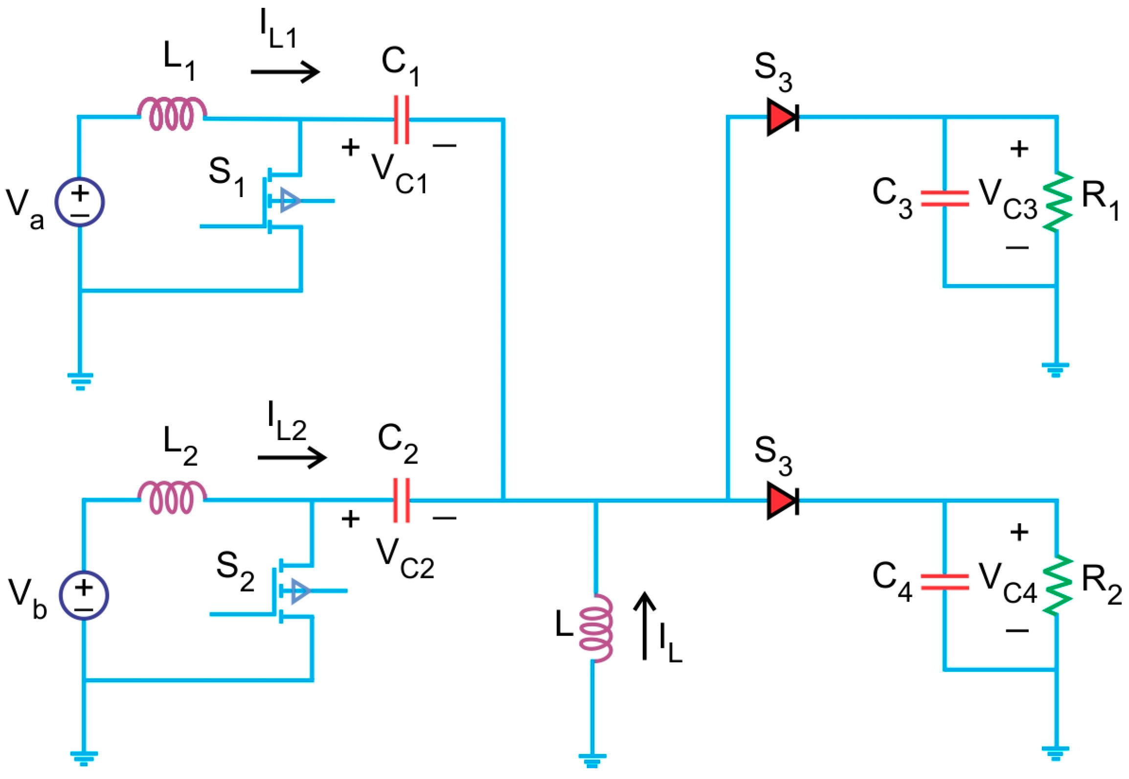
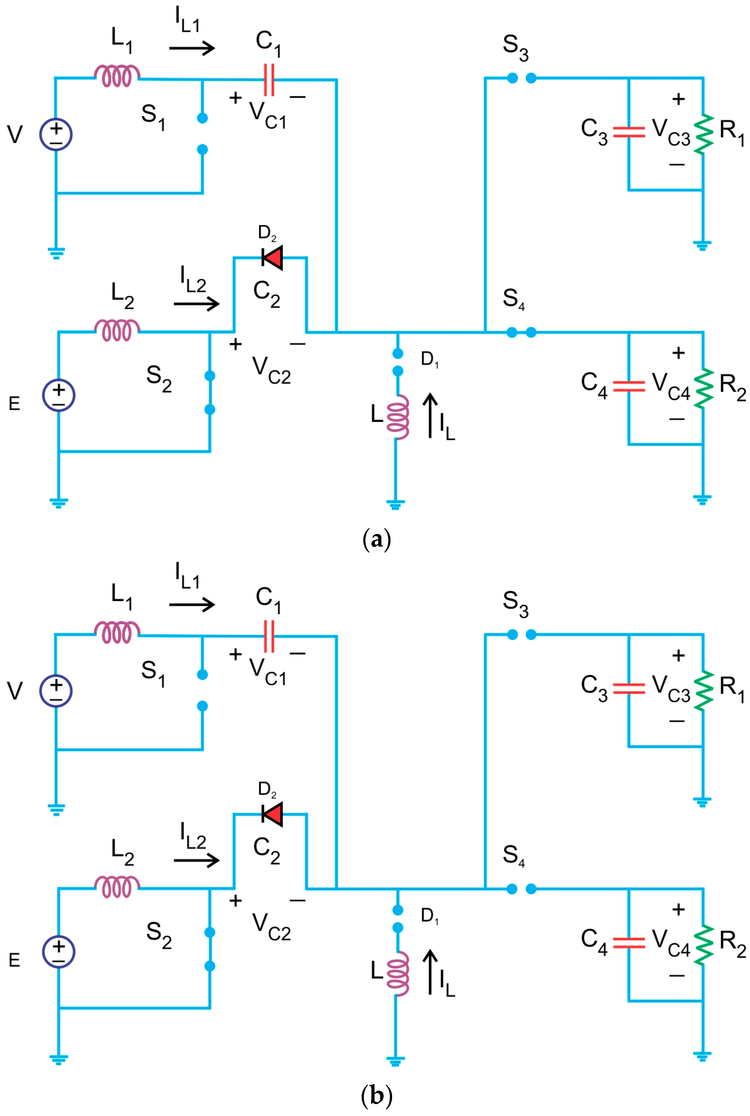
2. Proposed Structure
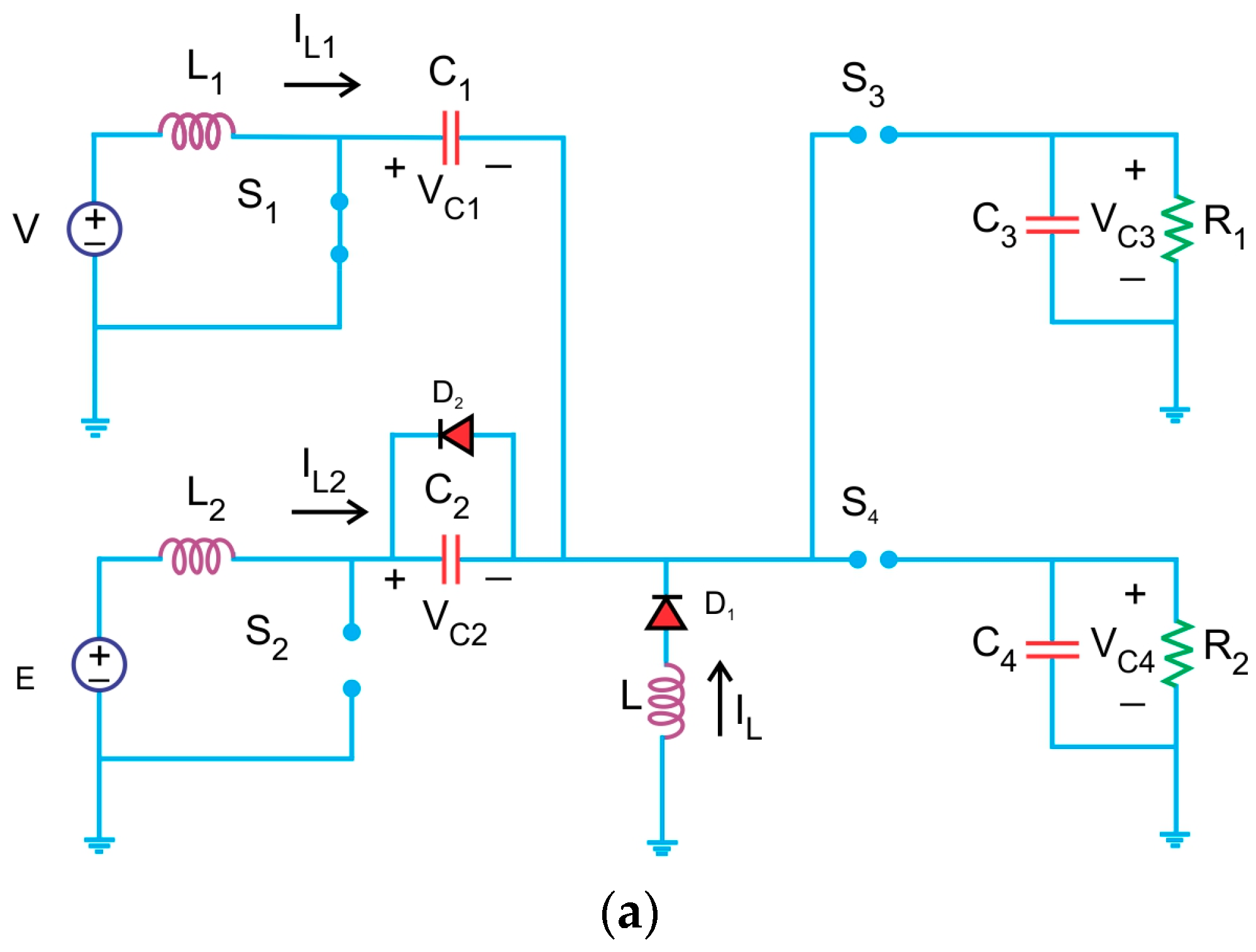
2.1. Four Port Non-Isolated Unidirectional Converter
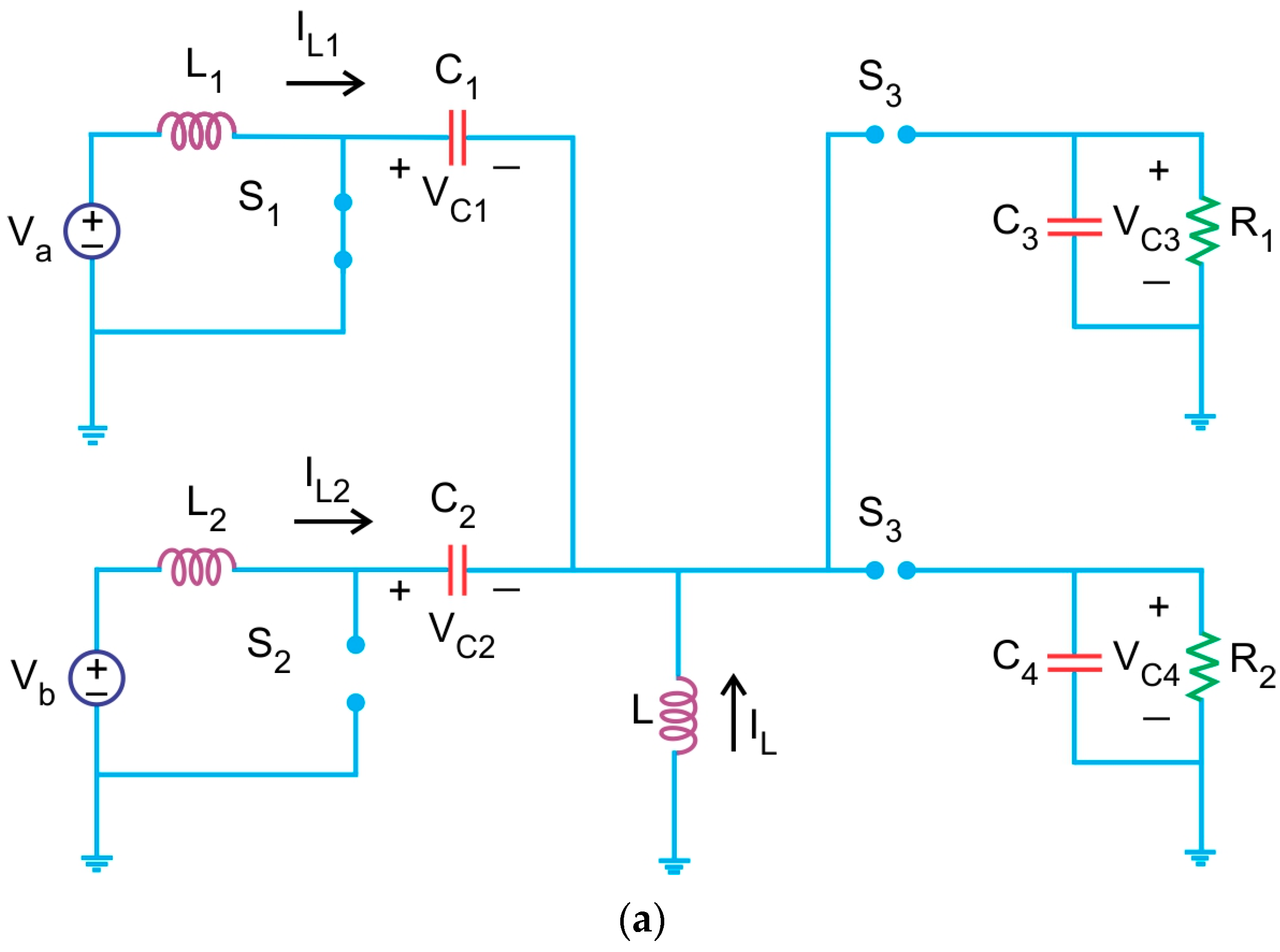
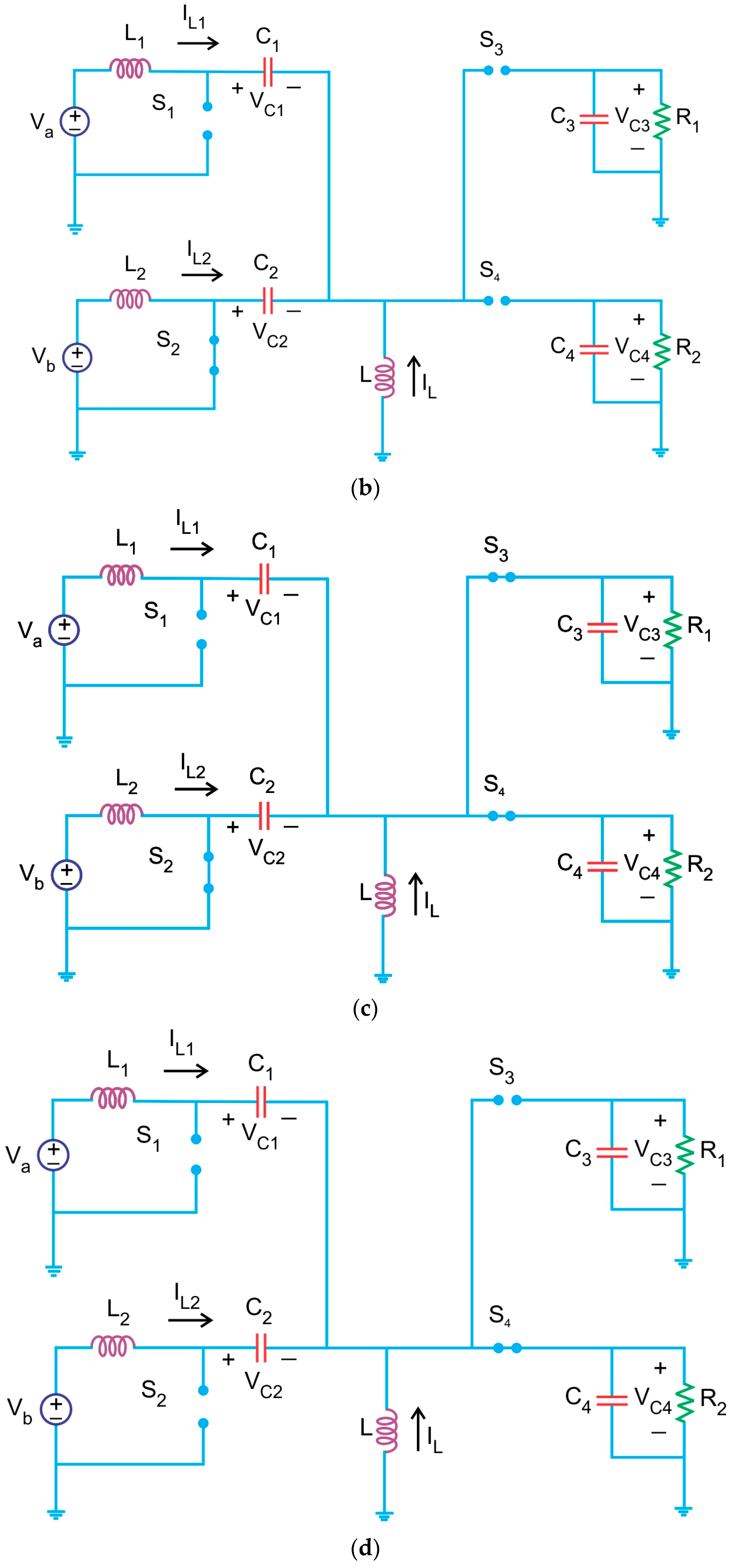
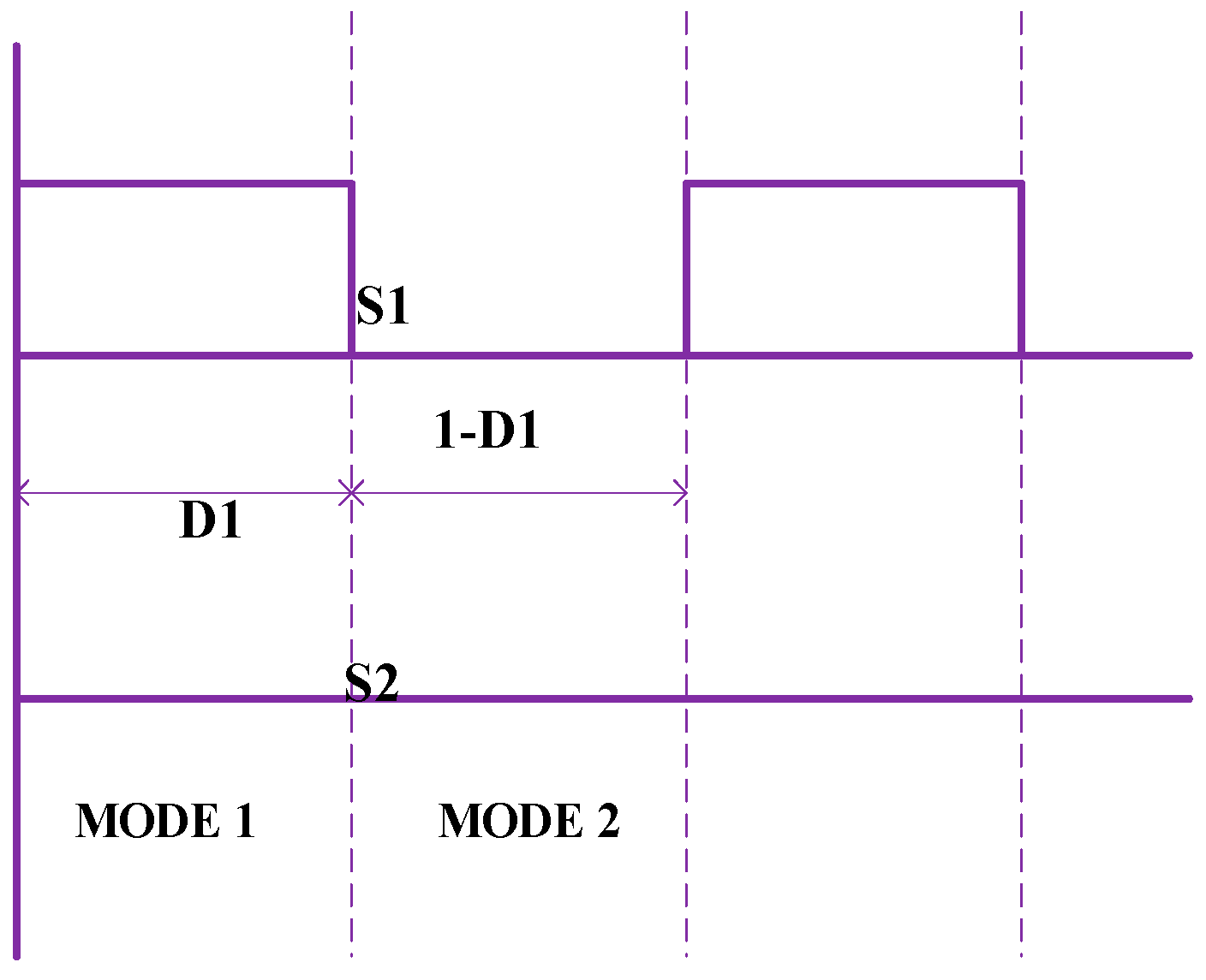
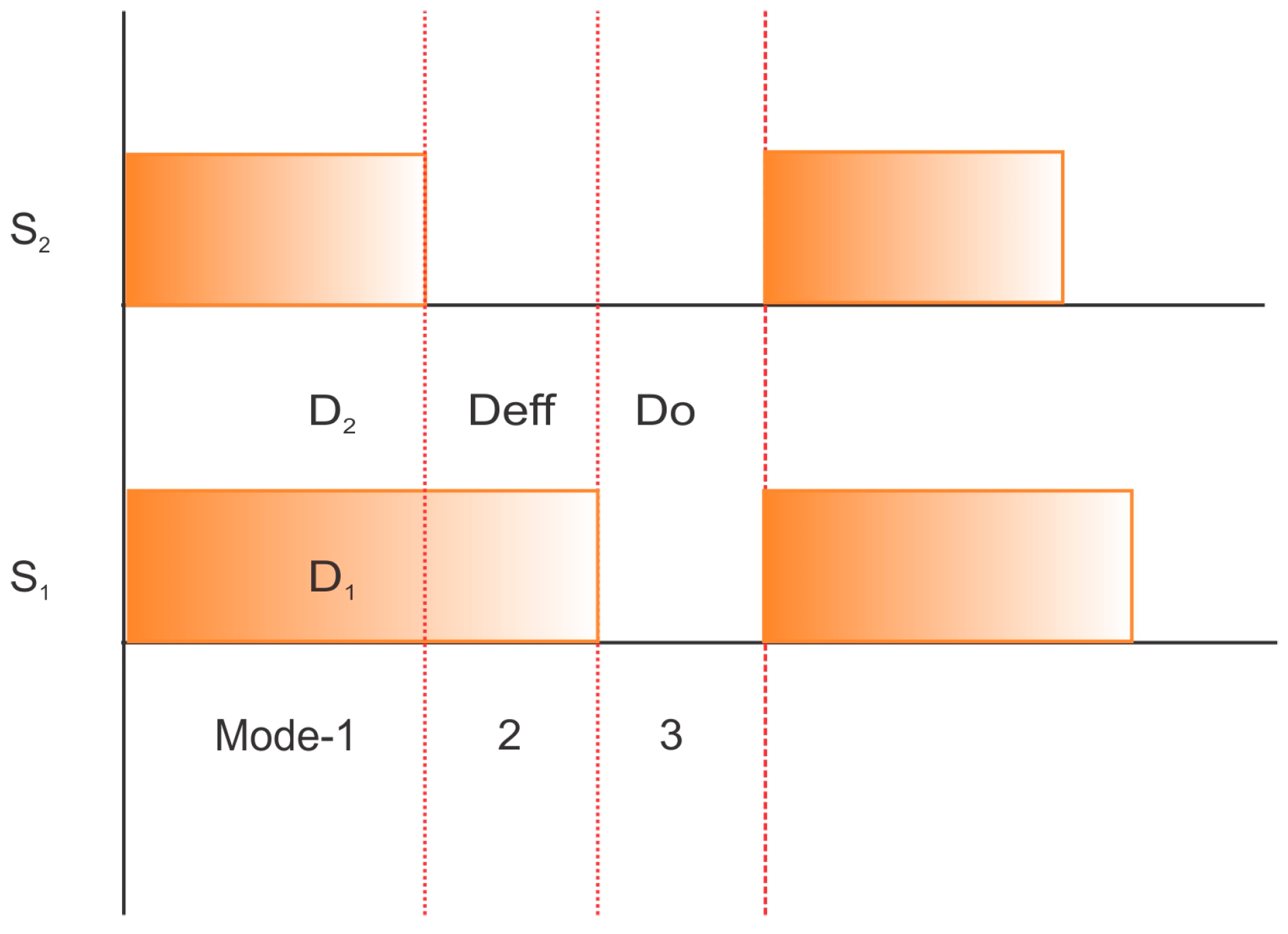
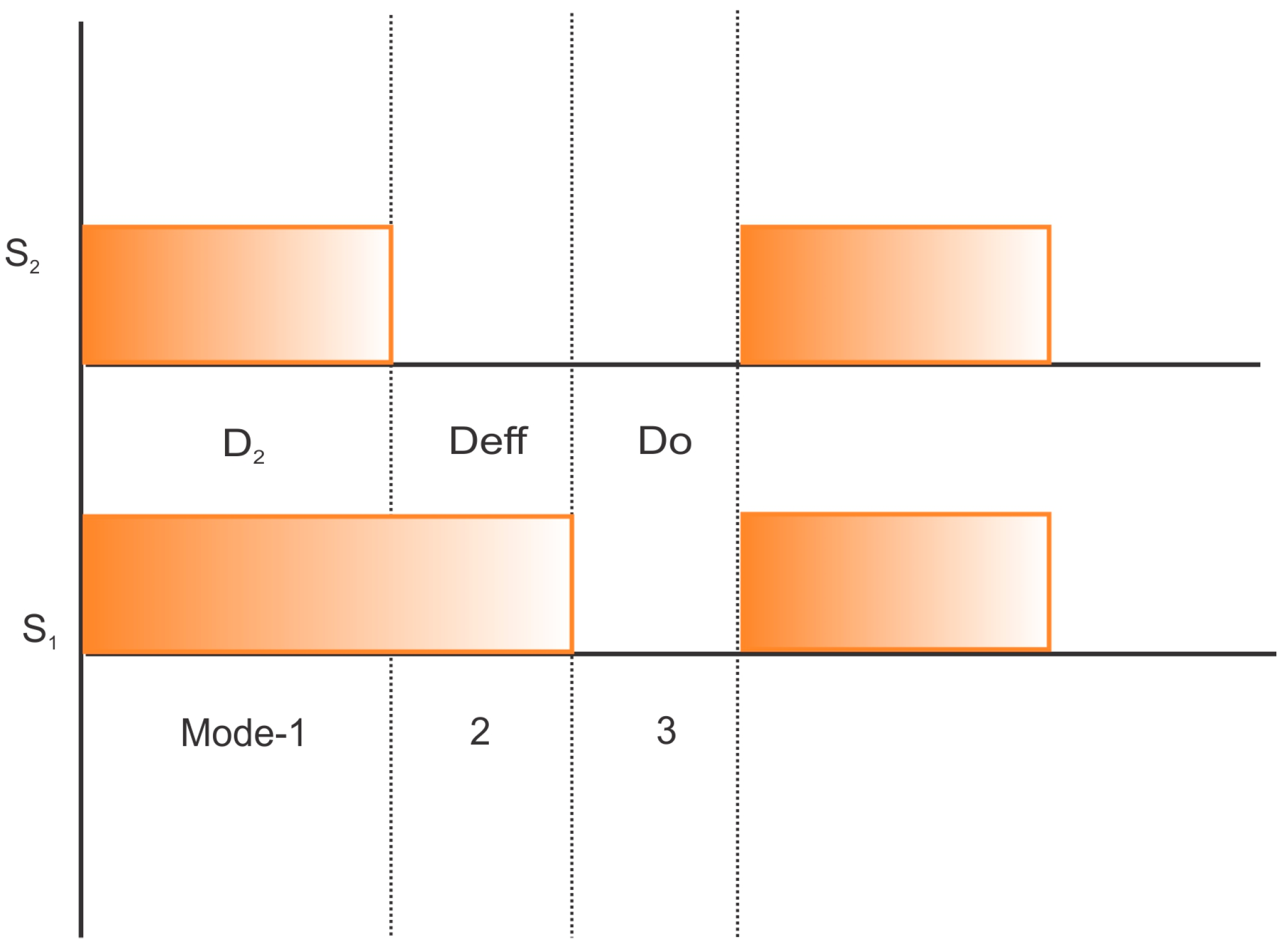
2.2. Operation Modes
2.3. Small Ripple Approximation of the Proposed Four-Port Converter
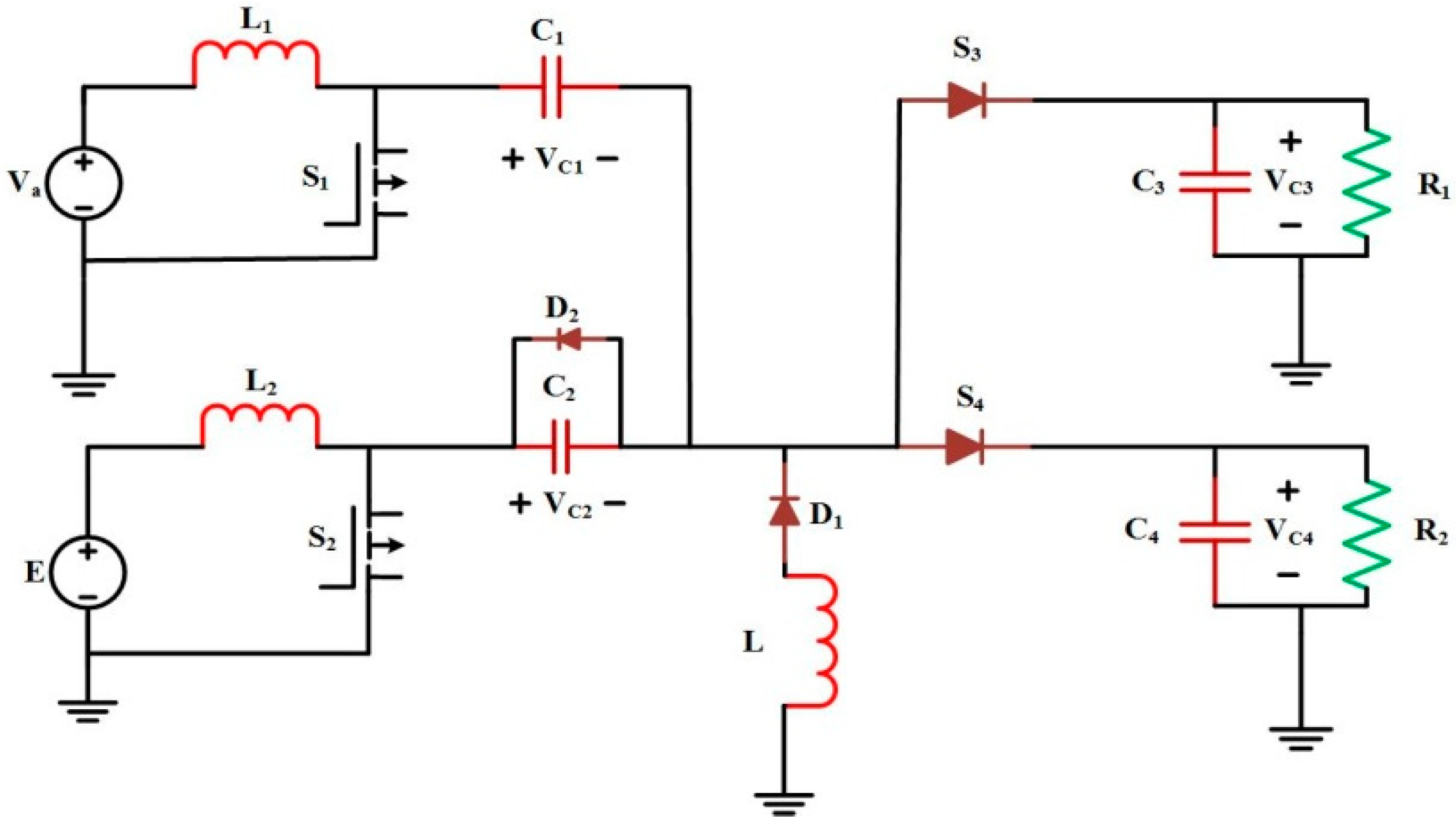
3. Four-Port Bi-Directional Converter
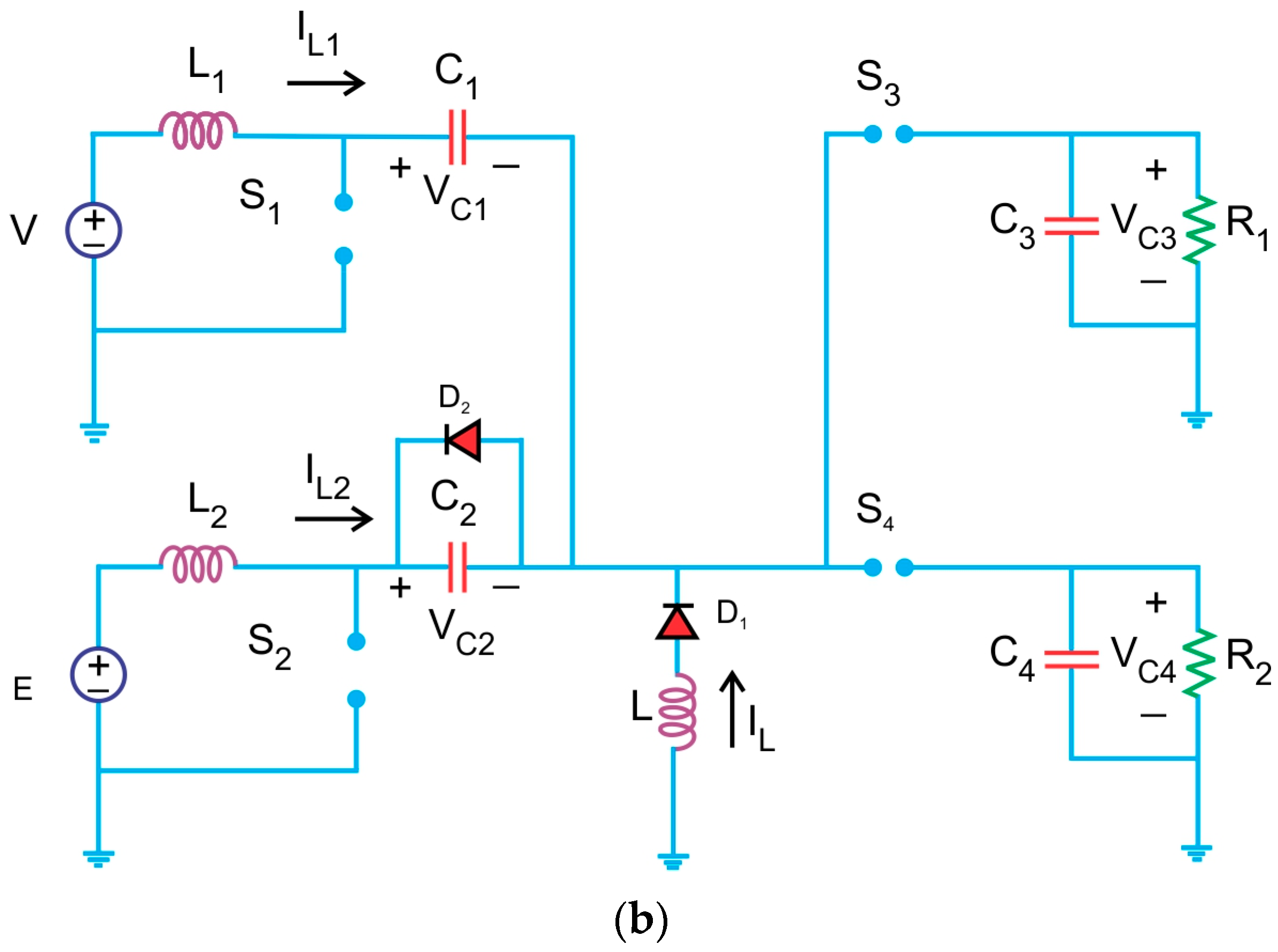
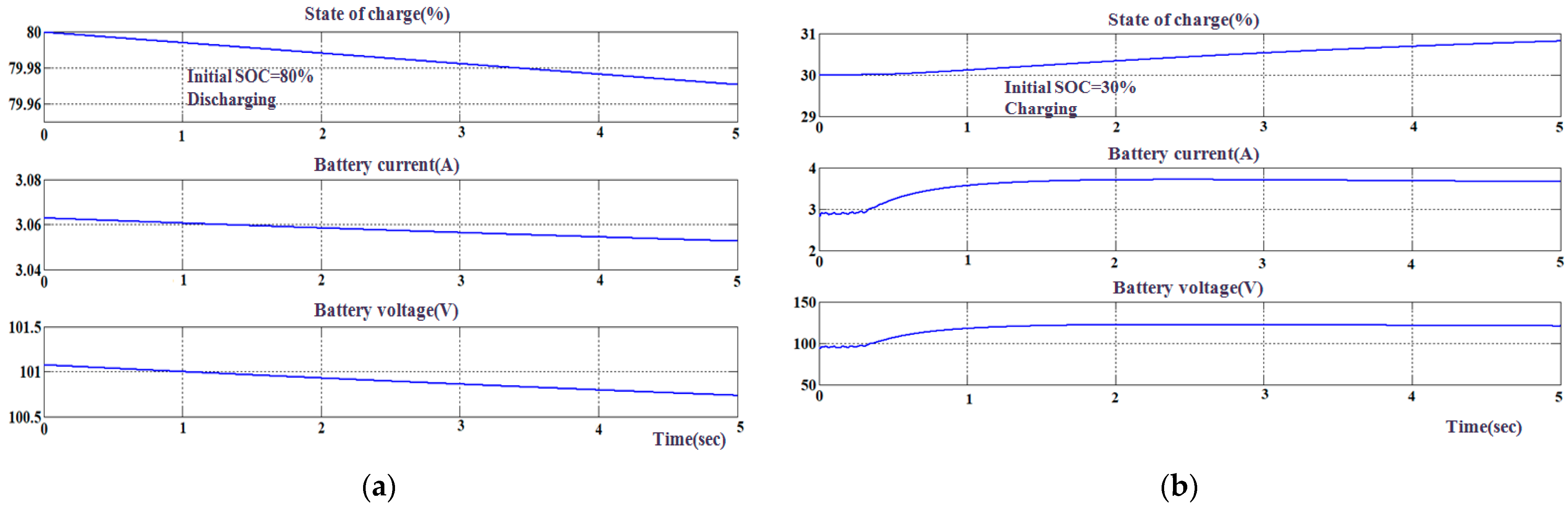
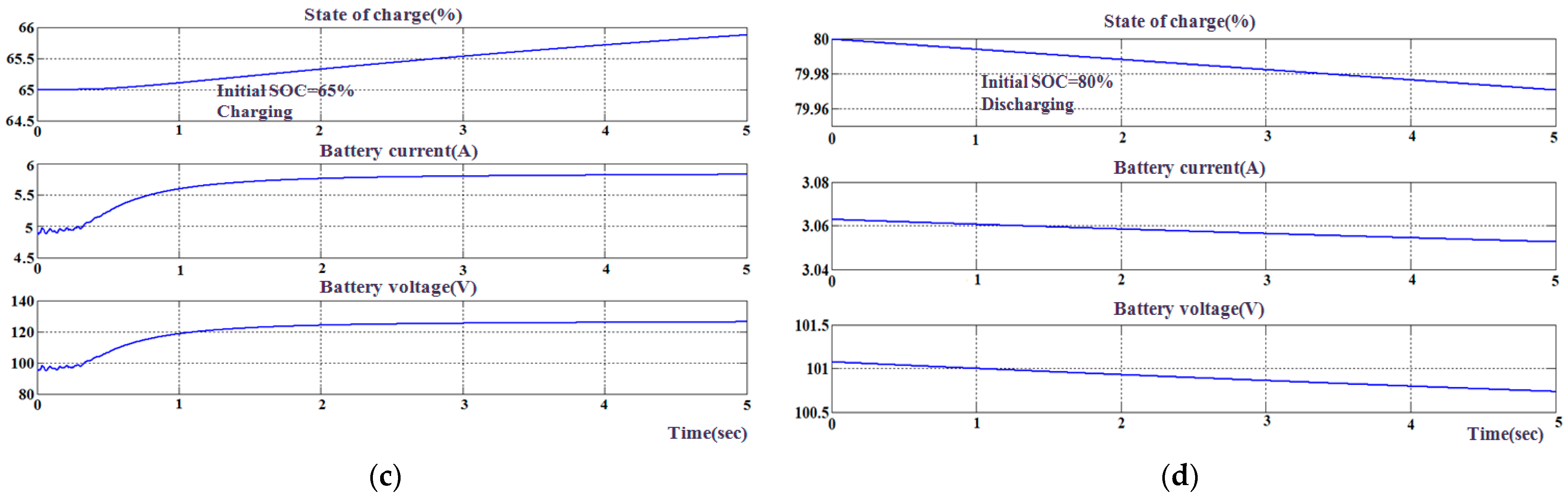
3.1. Four Port Non-Isolated Bidirectional Converter
- Va > E, charging condition
- Va < E, discharging condition
3.2. Power Flow Analysis from Source to Load for Four Port Non-Isolated Converter for Bi-Directional Topology
3.3. Power Flow Analysis from Load to Source for Four Port Non-Isolated Converter for Bi-Directional Topology
3.4. State Space Analysis of Four Port SEPIC Converter
4. Design of Controller
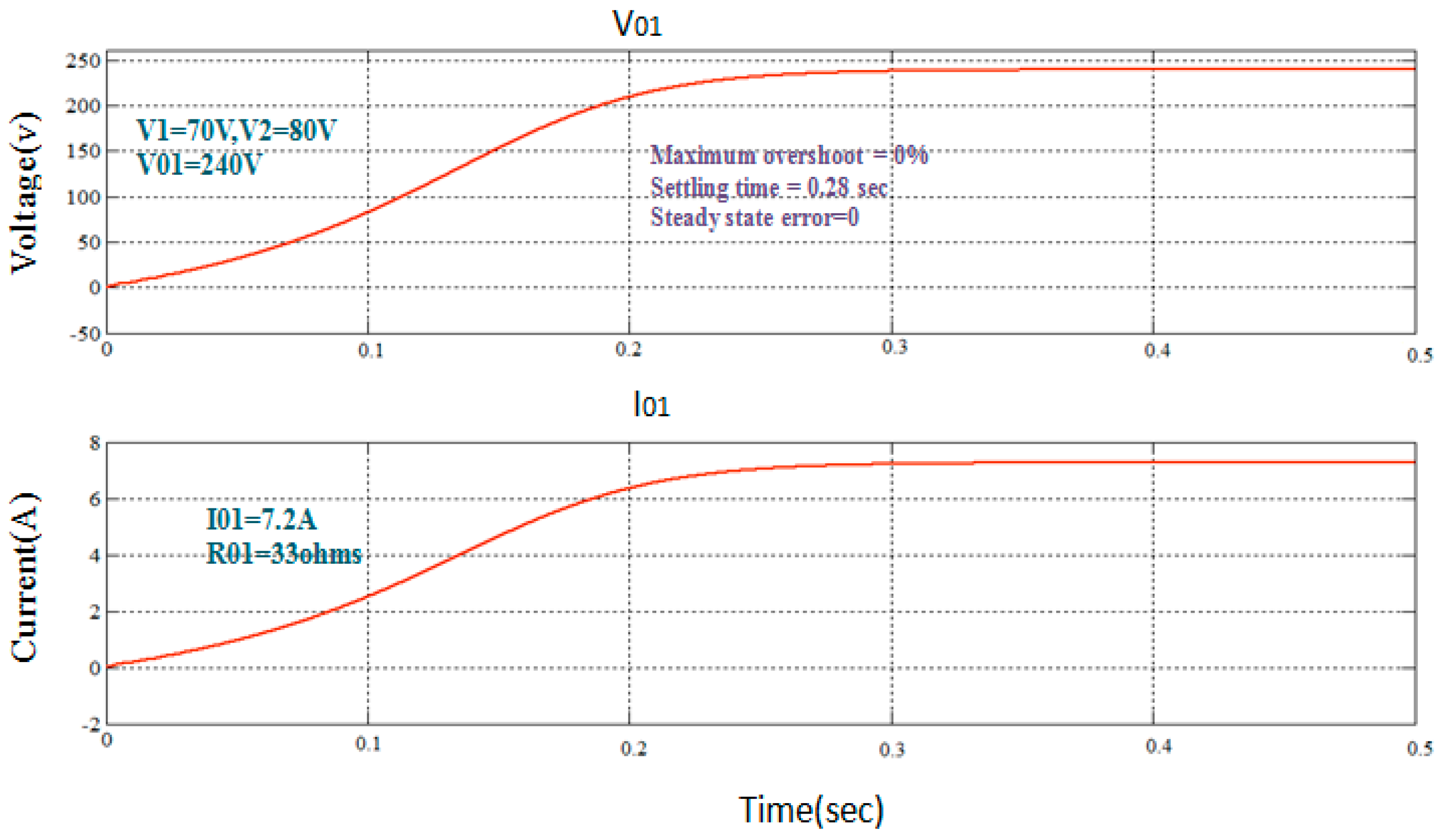
4.1. Closed Loop Unidirectional Controller
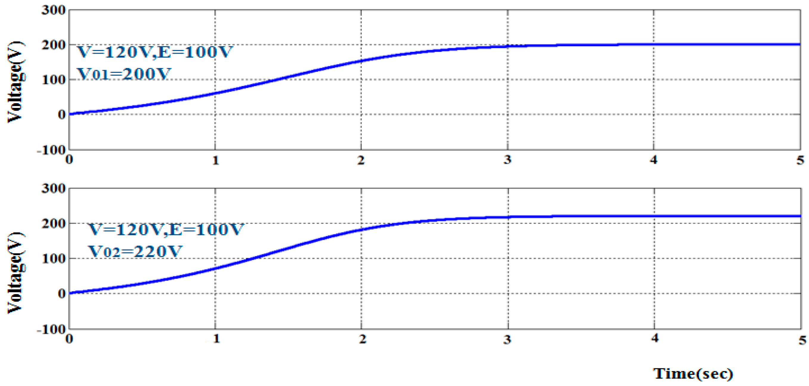
4.2. Closed Loop Bi-Directional Controller
- Case 1: When both PV and battery are active
- Case 2: When Just PV Is Inactive
- Case 3: When There is Just a Battery
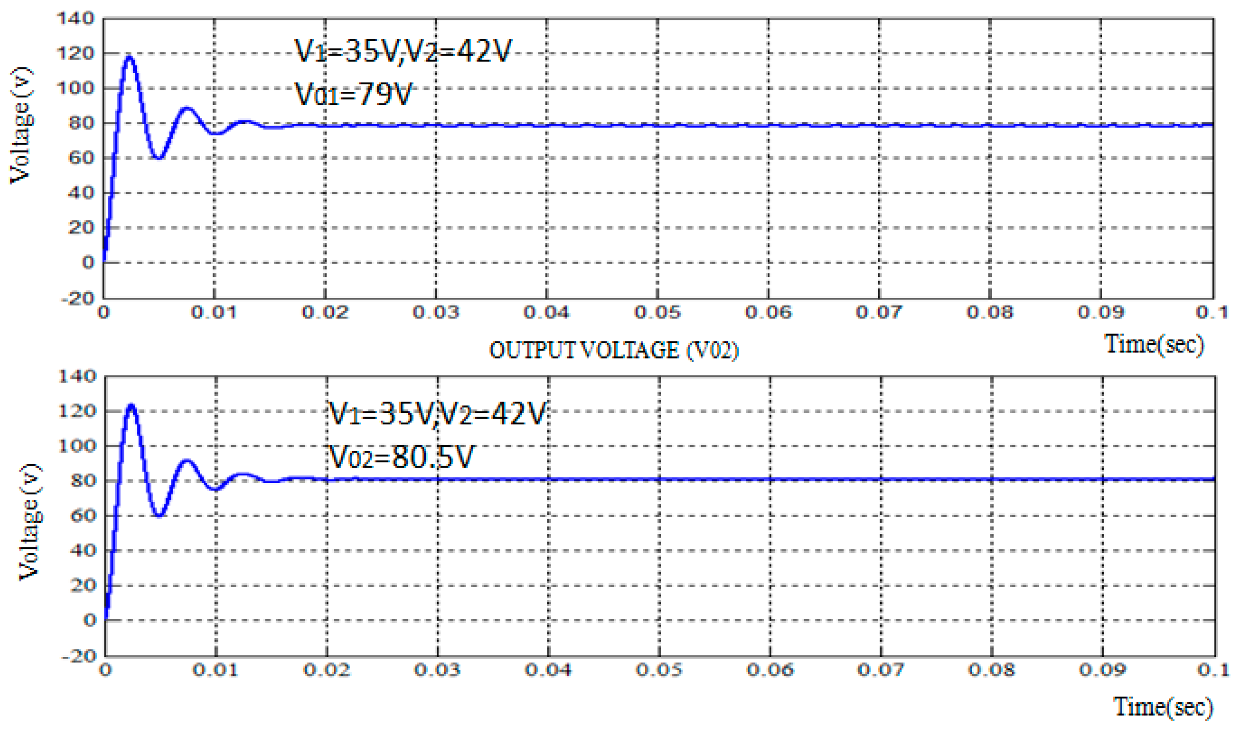
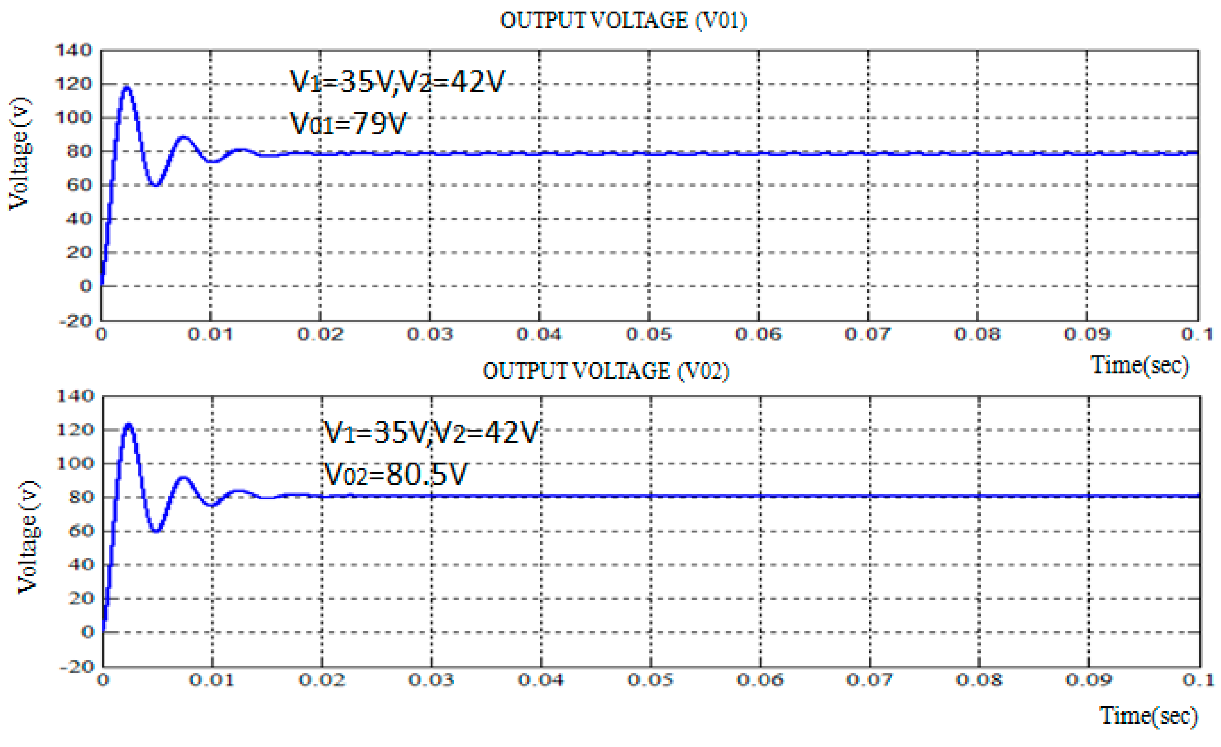
5. Results and Discussions
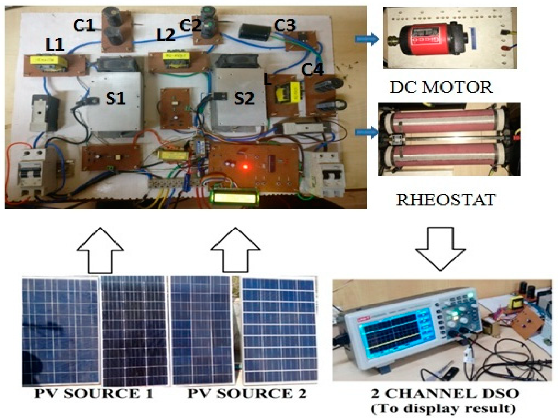
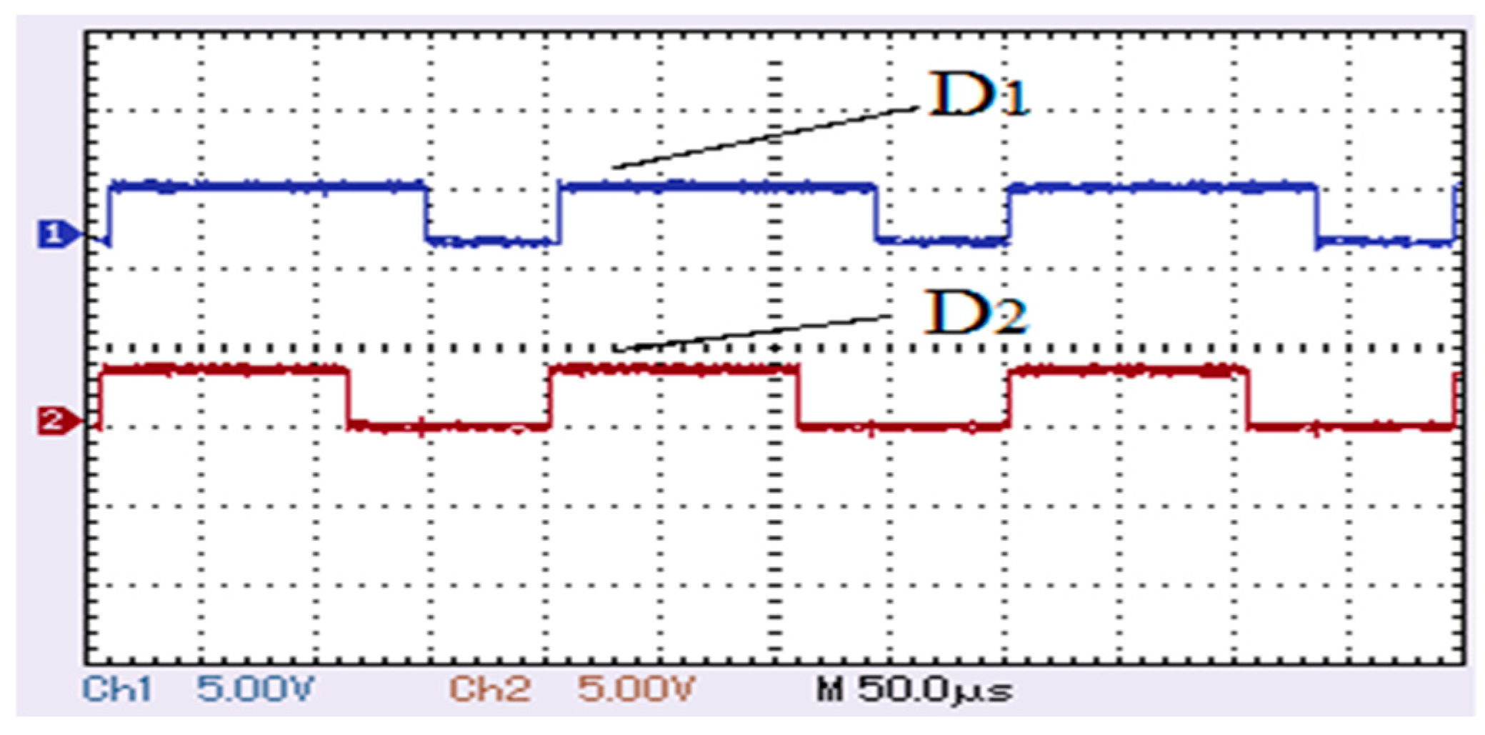
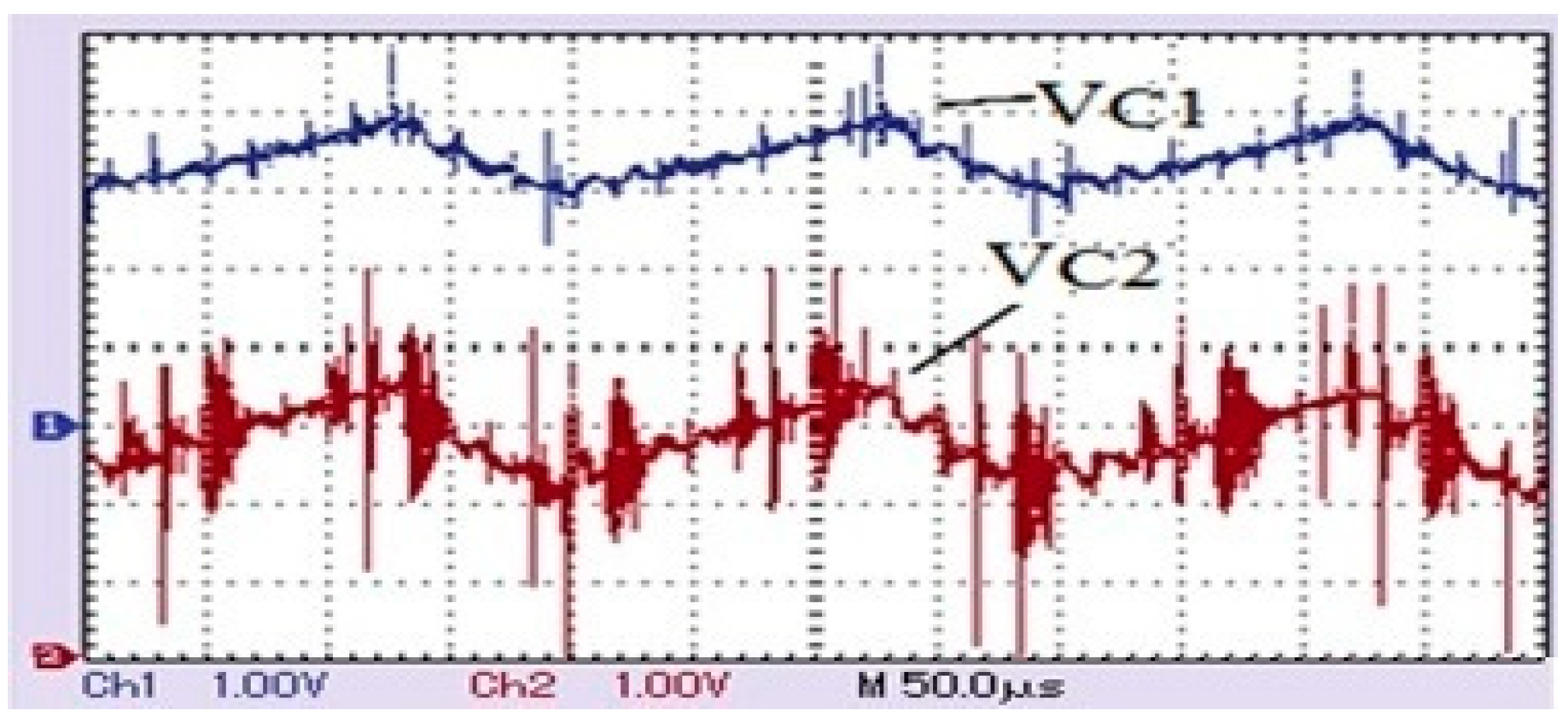
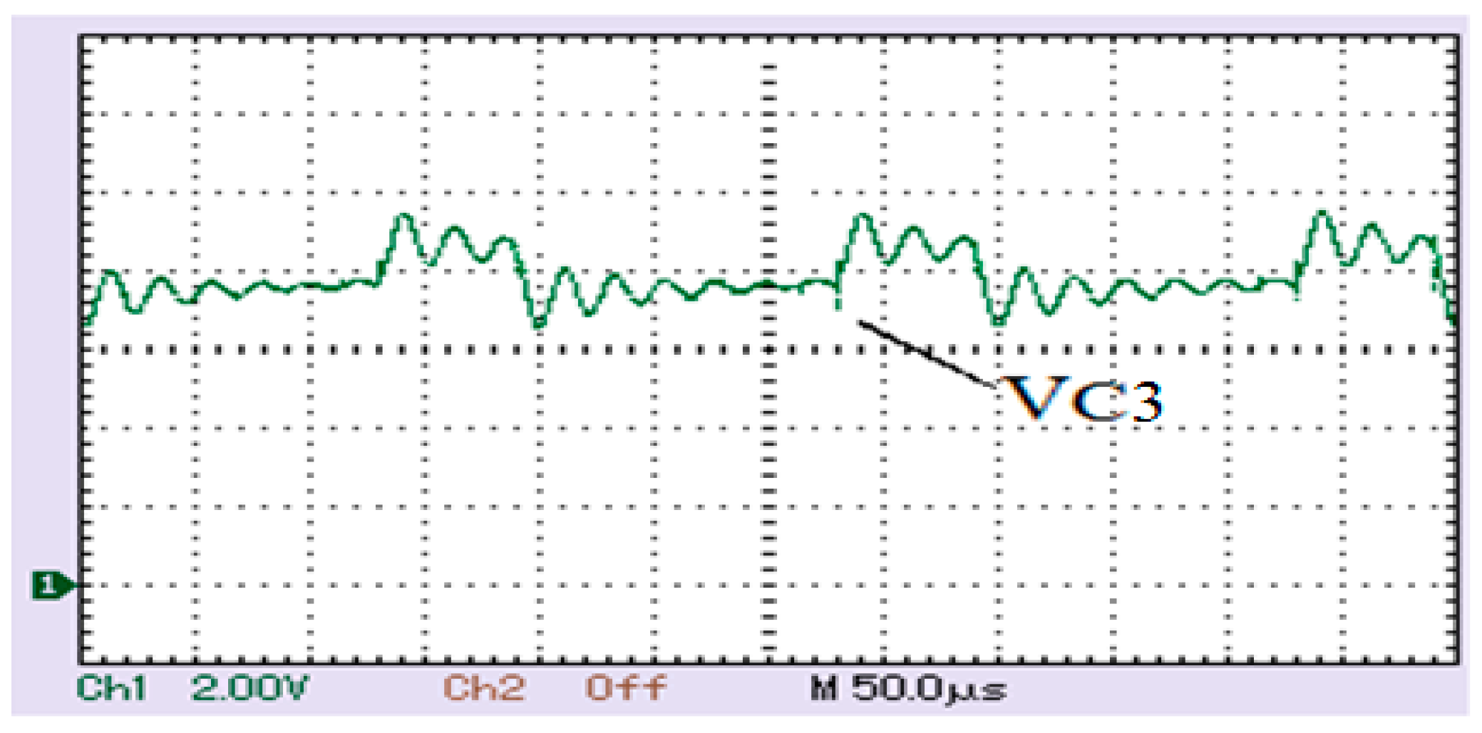
6. Experimental Results
Losses and Efficiency of Four-Port Topology
- VCE(sat) = 1.58 V
- IC = 15 A
- RON = 0.001 Ω
7. Conclusions
Author Contributions
Funding
Institutional Review Board Statement
Informed Consent Statement
Data Availability Statement
Acknowledgments
Conflicts of Interest
References
- Ouyang, Z.; Zhang, Z.; Andersen, M.A.E.; Thomsen, O.C. Four Quadrants Integrated Transformers for Dual-Input Isolated DC–DC Converters. IEEE Trans. Power Electron. 2012, 27, 2697–2702. [Google Scholar] [CrossRef]
- Wu, H.; Sun, K.; Chen, R.; Hu, H.; Xing, Y. Full-Bridge Three-Port Converters with Wide Input Voltage Range for Renewable Power Systems. IEEE Trans. Power Electron. 2012, 27, 3965–3974. [Google Scholar] [CrossRef]
- Wang, R.; Gu, Q.; Lu, S.; Tian, J.; Yin, Z.; Yin, L.; Zheng, W. FI-NPI: Exploring Optimal Control in Parallel Platform Systems. Electronics 2024, 13, 1168. [Google Scholar] [CrossRef]
- Mahmud, M.W.B.; Alam, A.Z.; Rahman, D.A. Improvement of Active Power Factor Correction Circuit for Switch Mode Power Supply Using Fly Back and Boost Topology. In Proceedings of the 2018 7th International Conference on Computer and Communication Engineering (ICCCE), Kuala Lumpur, Malaysia, 19–20 September 2018; pp. 437–440. [Google Scholar] [CrossRef]
- Tian, H.; Zhao, M.; Liu, J.; Wang, Q.; Yu, X.; Wang, Z. Dynamic Analysis and Sliding Mode Synchronization Control of Chaotic Systems with Conditional Symmetric Fractional-Order Memristors. Fractal Fract. 2024, 8, 307. [Google Scholar] [CrossRef]
- Zeng, J.; Qiao, W.; Qu, L.; Jiao, Y. An Isolated Multiport DC–DC Converter for Simultaneous Power Management of Multiple Different Renewable Energy Sources. IEEE J. Emerg. Sel. Top. Power Electron. 2014, 2, 70–78. [Google Scholar] [CrossRef]
- Cao, F.; Zhang, J.; Wu, H.; Hu, H.; Xing, Y.; Ma, X. A dual-input Boost-Buck converter with coupled inductors for TEG applications. In Proceedings of the 2013 IEEE Energy Conversion Congress and Exposition, Denver, CO, USA, 15–19 September 2013; pp. 2020–2025. [Google Scholar] [CrossRef]
- Ma, K.; Yang, J.; Liu, P. Relaying-Assisted Communications for Demand Response in Smart Grid: Cost Modeling, Game Strategies, and Algorithms. IEEE J. Sel. Areas Commun. 2020, 38, 48–60. [Google Scholar] [CrossRef]
- Palma, L.; Enjeti, P.N. A Modular Fuel Cell, Modular DC–DC Converter Concept for High Performance and Enhanced Reliability. IEEE Trans. Power Electron. 2009, 24, 1437–1443. [Google Scholar] [CrossRef]
- Jiao, N.; Wang, S.; Ma, J.; Liu, T.; Zhou, D. Sideband Harmonic Suppression Analysis Based on Vector Diagrams for CHB Inverters Under Unbalanced Operation. IEEE Trans. Ind. Electron. 2024, 71, 427–437. [Google Scholar] [CrossRef]
- Todorovic, M.H.; Palma, L.; Enjeti, P.N. Design of a Wide Input Range DC–DC Converter With a Robust Power Control Scheme Suitable for Fuel Cell Power Conversion. IEEE Trans. Ind. Electron. 2008, 55, 1247–1255. [Google Scholar] [CrossRef]
- Zhang, J.; Li, H.; Kong, X.; Zhou, J.; Shi, G.; Zang, J.; Wang, J. A Novel Multiple-Medium-AC-Port Power Electronic Transformer. IEEE Trans. Ind. Electron. 2024, 71, 6568–6578. [Google Scholar] [CrossRef]
- Hawke, J.T.; Krishnamoorthy, H.S.; Enjeti, P.N. A new utility-scale power converter for large fuel cell power plants with individual stack power control. In Proceedings of the 2012 Twenty-Seventh Annual IEEE Applied Power Electronics Conference and Exposition (APEC), Orlando, FL, USA, 5–9 February 2012; pp. 1482–1488. [Google Scholar] [CrossRef]
- Zhang, J.; Feng, X.; Zhou, J.; Zang, J.; Wang, J.; Shi, G.; Cai, X.; Li, Y. Series–Shunt Multiport Soft Normally Open Points. IEEE Trans. Ind. Electron. 2023, 70, 10811–10821. [Google Scholar] [CrossRef]
- Huang, Y.; Tse, C.K. Circuit Theoretic Classification of Parallel Connected DC–DC Converters. IEEE Trans. Circuits Syst. I: Regul. Pap. 2007, 54, 1099–1108. [Google Scholar] [CrossRef]
- Zhou, Y.; Song, Y.; Zhao, S.; Li, X.; Shao, L.; Yan, H.; Xu, Z.; Ding, S. A comprehensive aerodynamic-thermal-mechanical design method for fast response turbocharger applied in aviation piston engines. Propuls. Power Res. 2024, 13, 145–165. [Google Scholar] [CrossRef]
- Wai, R.-J.; Lin, C.-Y.; Chen, B.-H. High-Efficiency DC–DC Converter With Two Input Power Sources. IEEE Trans. Power Electron. 2012, 27, 1862–1875. [Google Scholar] [CrossRef]
- Wang, H.; Sun, W.; Jiang, D.; Qu, R. A MTPA and Flux-Weakening Curve Identification Method Based on Physics-Informed Network Without Calibration. IEEE Trans. Power Electron. 2023, 38, 12370–12375. [Google Scholar] [CrossRef]
- Zeng, J.; Qiao, W.; Qu, L. An Isolated Three-Port Bidirectional DC–DC Converter for Photovoltaic Systems With Energy Storage. IEEE Trans. Ind. Appl. 2015, 51, 3493–3503. [Google Scholar] [CrossRef]
- Shirkhani, M.; Tavoosi, J.; Danyali, S.; Sarvenoee, A.K.; Abdali, A.; Mohammadzadeh, A.; Zhang, C. A review on microgrid decentralized energy/voltage control structures and methods. Energy Rep. 2023, 10, 368–380. [Google Scholar] [CrossRef]
- Li, Y.; Ruan, X.; Yang, D.; Liu, F.; Tse, C.K. Synthesis of Multiple-Input DC/DC Converters. IEEE Trans. Power Electron. 2010, 25, 2372–2385. [Google Scholar] [CrossRef]
- Liang, J.; Feng, J.; Lu, Y.; Yin, G.; Zhuang, W.; Mao, X. A Direct Yaw Moment Control Framework Through Robust T-S Fuzzy Approach Considering Vehicle Stability Margin. IEEE/ASME Trans. Mechatron. 2024, 29, 166–178. [Google Scholar] [CrossRef]
- Shen, Z.; Chang, X.; Wang, W.; Tan, X.; Yan, N.; Min, H. Predictive digital current control of single-inductor multiple-output converters in CCM with low cross regulation. IEEE Trans. Power Electron. 2012, 27, 1917–1925. [Google Scholar] [CrossRef]
- Yaghoubi, E.; Yaghoubi, E.; Khamees, A.; Razmi, D.; Lu, T. A systematic review and meta-analysis of machine learning, deep learning, and ensemble learning approaches in predicting EV charging behavior. Eng. Appl. Artif. Intell. 2024, 135, 108789. [Google Scholar] [CrossRef]
- Wu, H.; Chen, R.; Zhang, J.; Xing, Y.; Hu, H.; Ge, H. A Family of Three-Port Half-Bridge Converters for a Stand-Alone Renewable Power System. IEEE Trans. Power Electron. 2011, 26, 2697–2706. [Google Scholar] [CrossRef]
- Yang, Y.; Zhao, Y.; Yan, G.; Mu, G.; Chen, Z. Real time aggregation control of P2H loads in a virtual power plant based on a multi-period stackelberg game. Energy 2024, 303, 131484. [Google Scholar] [CrossRef]
- Behjati, H.; Davoudi, A. Power Budgeting Between Diversified Energy Sources and Loads Using a Multiple-Input Multiple-Output DC–DC Converter. IEEE Trans. Ind. Appl. 2013, 49, 2761–2772. [Google Scholar] [CrossRef]
- Yang, Y.; Wei, X.; Yao, W.; Lan, J. Broadband electrical impedance matching of sandwiched piezoelectric ultrasonic transducers for structural health monitoring of the rail in-service. Sens. Actuators A: Phys. 2023, 364, 114819. [Google Scholar] [CrossRef]
- Wu, H.; Xu, P.; Hu, H.; Zhou, Z.; Xing, Y. Multiport Converters Based on Integration of Full-Bridge and Bidirectional DC–DC Topologies for Renewable Generation Systems. IEEE Trans. Ind. Electron. 2014, 61, 856–869. [Google Scholar] [CrossRef]
- Zhu, C.; Zhang, Y.; Wang, M.; Deng, J.; Cai, Y.; Wei, W.; Guo, M. Simulation and comprehensive study of a new trigeneration process combined with a gas turbine cycle, involving transcritical and supercritical CO2 power cycles and Goswami cycle. J. Therm. Anal. Calorim. 2024, 149, 6361–6384. [Google Scholar] [CrossRef]
- Meng, Q.; Hussain, S.; Luo, F.; Wang, Z.; Jin, X. An Online Reinforcement Learning-based Energy Management Strategy for Microgrids with Centralized Control. IEEE Trans. Ind. Appl. 2024. [Google Scholar] [CrossRef]
- Wu, H.; Xing, Y.; Xia, Y.; Sun, K. A family of non-isolated three-port converters for stand-alone renewable power system. In Proceedings of the IECON 2011-37th Annual Conference of the IEEE Industrial Electronics Society, Melbourne, VIC, Australia, 7–10 November 2011; pp. 1030–1035. [Google Scholar] [CrossRef]
- Meng, Q.; Tong, X.; Hussain, S.; Luo, F.; Zhou, F.; Liu, L.; He, Y.; Jin, X.; Li, B. Revolutionizing photovoltaic consumption and electric vehicle charging: A novel approach for residential distribution systems. IET Gener. Transm. Distrib. 2024, 18, 2822–2833. [Google Scholar] [CrossRef]
- Dueñas-García, I.; Rosas-Caro, J.C.; Robles-Campos, H.R.; Posada, J.; Valdez-Resendiz, J.E.; Valderrabano-Gonzalez, A.; Gabbar, H.A.; Babaiahgari, B. A Symmetric Sixth-Order Step-Up Converter with Asymmetric PWM Achieved with Small Energy Storage Components. Symmetry 2024, 16, 460. [Google Scholar] [CrossRef]
- Khan, M.R.; Alam, I.; Khan, M.R. Inverter-Less Integration of Roof-Top Solar PV with Grid Connected Industrial Drives. Energies 2023, 16, 2060. [Google Scholar] [CrossRef]
- Lu, Y.; Tan, C.; Ge, W.; Zhao, Y.; Wang, G. Adaptive disturbance observer-based improved super-twisting sliding mode control for electromagnetic direct-drive pump. Smart Mater. Struct. 2023, 32, 17001. [Google Scholar] [CrossRef]
- Jena, C.J.; Ray, P.K. Power Management in Three-Phase Grid-Integrated PV System with Hybrid Energy Storage System. Energies 2023, 16, 2030. [Google Scholar] [CrossRef]
- Morel, C.; Akrad, A. Open-Circuit Fault Detection and Location in AC-DC-AC Converters Based on Entropy Analysis. Energies 2023, 16, 1959. [Google Scholar] [CrossRef]
- Wang, J.; Liu, T.; Ma, K. Flexible and Low-Cost Emulation of Control Behaviors for Testing and Teaching of AC Microgrid. Energies 2023, 16, 1905. [Google Scholar] [CrossRef]
- Awais, M.; Khan, L.; Khan, S.G.; Awais, Q.; Jamil, M. Adaptive Neural Network Q-Learning-Based Full Recurrent Adaptive NeuroFuzzy Nonlinear Control Paradigms for Bidirectional-Interlinking Converter in a Grid-Connected Hybrid AC-DC Microgrid. Energies 2023, 16, 1902. [Google Scholar] [CrossRef]
- Mahjoub, S.; Chrifi-Alaoui, L.; Drid, S.; Derbel, N. Control and Implementation of an Energy Management Strategy for a PV–Wind–Battery Microgrid Based on an Intelligent Prediction Algorithm of Energy Production. Energies 2023, 16, 1883. [Google Scholar] [CrossRef]
- Narayanaswamy, J.; Mandava, S. Non-Isolated Multiport Converter for Renewable Energy Sources: A Comprehensive Review. Energies 2023, 16, 1834. [Google Scholar] [CrossRef]
- Chang, Y.-N.; Yan, Y.-H.; Huang, S.-M. An Isolated Three-Port Power Converter with 2C3L and 2C2L Resonant Circuits. Energies 2023, 16, 1830. [Google Scholar] [CrossRef]
- Kumar, A.; Bertoluzzo, M.; Jha, R.K.; Sagar, A. Analysis of Losses in Two Different Control Approaches for S-S Wireless Power Transfer Systems for Electric Vehicle. Energies 2023, 16, 1795. [Google Scholar] [CrossRef]
- Kim, T.-G.; Lee, H.; An, C.-G.; Yi, J.; Won, C.-Y. Hybrid AC/DC Microgrid Energy Management Strategy Based on Two-Step ANN. Energies 2023, 16, 1787. [Google Scholar] [CrossRef]
- El Zoghby, H.M.; Safwat, A.; Bendary, A.F.; Hazem, A.B.; Ramadan, H.S.; Elmesalawy, M.M.; Afia, R.S. Islanded Microgrids Frequency Support Using Green Hydrogen Energy Storage with AI-Based Controllers. IEEE Access 2024. [Google Scholar] [CrossRef]


| Mode | Switches on | Switches off | L1 | L2 | L | C1 | C2 | C3 | C4 | Power Flow |
|---|---|---|---|---|---|---|---|---|---|---|
| I | S1 | S2, S3, S4 | C | D | C | C | D | D | D | Source to load |
| II | S2 | S1,S3, S4 | D | C | C | D | C | D | D | Source to load |
| III | S3, S4 | S1, S2 | D | D | C | D | D | C | C | Source to load |
| IV | S4 | S1,S2,S3 | D | D | D | D | D | D | C | Source to load |
| Component | Value |
|---|---|
| Inductor L1 at PVSC1 | 15 mH |
| Inductor L2 at PVSC2 | 15 mH |
| Inductor L at PVLC | 15 mH |
| Capacitor C1 at PVSC1 | 0.54 mF |
| Capacitor C2 at PVSC2 | 0.54 mF |
| Capacitor C at PVLC | 0.54 mF |
| Switching frequency, f | 5000 Hz |
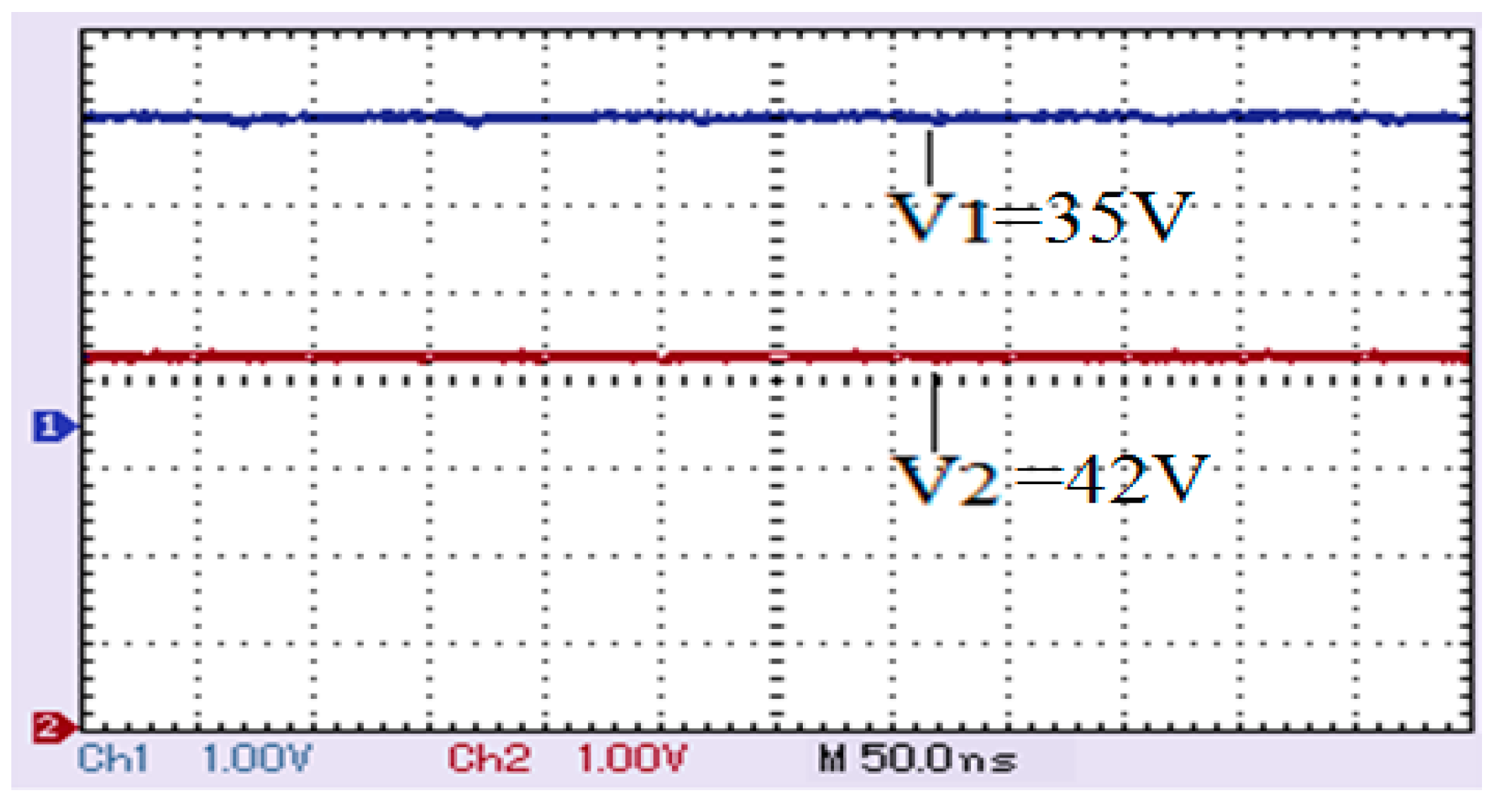
| PV source 1, V1 | 35 V |
| PV source 1, V2 | 42 V |
| Duty cycle of PVSC1, D1 | 67% |
| Duty cycle of PVSC2, D2 | 50% |
| Switching frequency, f | 5000 Hz |
| PV source 1, V1 | 35 V |
| PV source 1, V2 | 42 V |
| Duty cycle of PVSC1, D1 | 67% |
| Duty cycle of PVSC2, D2 | 50% |
| Switching frequency, f | 5000 Hz |
| V01, V02 from hardware setup | 79 V, 81 V |
| V01, V02 from MATLAB simulation | 79 V, 80.5 V |
| V01, V02 from mathematical formula | 80.66 V, 82.22 V |
Disclaimer/Publisher’s Note: The statements, opinions and data contained in all publications are solely those of the individual author(s) and contributor(s) and not of MDPI and/or the editor(s). MDPI and/or the editor(s) disclaim responsibility for any injury to people or property resulting from any ideas, methods, instructions or products referred to in the content. |
© 2024 by the authors. Licensee MDPI, Basel, Switzerland. This article is an open access article distributed under the terms and conditions of the Creative Commons Attribution (CC BY) license (https://creativecommons.org/licenses/by/4.0/).
Share and Cite
Chandrasekar, A.; Subramanian, V.; Rajamanickam, N.; Shorfuzzaman, M.; Emara, A. Design and Control of Four-Port Non-Isolated SEPIC Converter for Hybrid Renewable Energy Systems. Sustainability 2024, 16, 8423. https://doi.org/10.3390/su16198423
Chandrasekar A, Subramanian V, Rajamanickam N, Shorfuzzaman M, Emara A. Design and Control of Four-Port Non-Isolated SEPIC Converter for Hybrid Renewable Energy Systems. Sustainability. 2024; 16(19):8423. https://doi.org/10.3390/su16198423
Chicago/Turabian StyleChandrasekar, Anuradha, Vijayalakshmi Subramanian, Narayanamoorthi Rajamanickam, Mohammad Shorfuzzaman, and Ahmed Emara. 2024. "Design and Control of Four-Port Non-Isolated SEPIC Converter for Hybrid Renewable Energy Systems" Sustainability 16, no. 19: 8423. https://doi.org/10.3390/su16198423
APA StyleChandrasekar, A., Subramanian, V., Rajamanickam, N., Shorfuzzaman, M., & Emara, A. (2024). Design and Control of Four-Port Non-Isolated SEPIC Converter for Hybrid Renewable Energy Systems. Sustainability, 16(19), 8423. https://doi.org/10.3390/su16198423