Abstract
Reducing reliance on fossil fuels has driven the development of innovative technologies in recent years due to the increasing levels of greenhouse gases in the atmosphere. Since the automotive industry is one of the main contributors of high CO2 emissions, the introduction of more sustainable solutions in this sector is fundamental. This paper presents a novel energy management system for fuel cell hybrid electric vehicles based on dynamic programming and adaptive neuro fuzzy inference system methodologies to optimize energy distribution between battery and fuel cell, therefore enhancing powertrain efficiency and reducing hydrogen consumption. Three different approaches have been considered for performance assessment through a simulation platform developed in MATLAB/Simulink 2023a. Further validation has been conducted via a rapid control prototyping device, showcasing significant improvements in hydrogen usage and operational efficiency across different drive cycles. Results manifest that the developed controllers successfully replicate the optimal control trajectory, providing a robust and computationally feasible solution for real-world applications. This research highlights the potential of combining advanced control strategies to meet performance and environmental demands of modern heavy-duty vehicles.
1. Introduction
The increase in greenhouse gases (GHG) in the atmosphere has played a major role in driving the development of new technologies aimed at reducing reliance on fossil fuels. The automotive industry, responsible for the 19% of total CO2 emissions [1], is in urgent need for the introduction of innovative solutions that will help mitigate the harmful environmental impact associated with this sector, for which different laws, restrictions and guidelines have arisen in recent years [2].
In order to approach this urgent concern, it is crucial to introduce alternative methods of powering vehicles to the global market while ensuring that performance, comfort and ease of use remain uncompromised. The electrification of the powertrain system is one of the most suitable and well-researched alternatives to internal combustion engine (ICE)-based vehicles, which heavily rely on fossil fuels, providing a more sustainable and environmentally friendly means of transportation [3].
A significant contributor to CO2 emissions within the transportation sector emerge from the predominant reliance on conventional heavy-duty vehicles (HDVs) [4]. Therefore, the implementation of electrification technologies is vital to decrease the substantial environmental impact caused by this sector.
As a matter of fact, the heightened fuel efficiency associated with hybrid electric vehicles (HEVs) in contrast to conventional vehicles might be attributed to the optimization of engine functionality and the recovery of kinetic energy through regenerative braking [5]. To this end, fuel cell hybrid electric vehicles (FCHEVs) present themselves as an environmentally friendly and suitable solution for HDVs, due to their negligible emissions as power is produced by a chemical reaction between hydrogen and oxygen, resulting in water as the only waste [6]. Boasting an extensive driving range and requiring minimal refueling time, hydrogen emerges as an economically, socially, and environmentally sustainable energy source [7]. Hydrogen offers several benefits in comparison to other varieties of battery electric vehicles (BEV), such as a higher energy density, higher scalability due to the various production methods available, or faster refueling times with minimal downtime [8]. The architecture of these vehicles incorporates an additional energy storage system (ESS) in the form of a battery or ultracapacitor serving as support for the fuel cell (FC), capable of being charged and discharged in response to power demand [9]. When employing a FC as the primary energy source and a battery or ultracapacitor as the supporting ESS in an HEV, various considerations must be addressed to guarantee an efficient and seamless operation, e.g., design configuration, component sizing, and power management methods [10]. The formulation of effective control strategies within power management methodologies has demonstrated a pronounced influence on powertrain performance, offering advantages in term of cost-effectiveness and the capability to selectively address multiple objectives [11].
In light of this perspective, the design of a proper energy management system (EMS), in charge of providing a real-time regulation of the power required to drive the vehicle at the desired speed by both FC and ESS is fundamental for ensuring adequate performance. The primary objective of this approach is to augment the operational efficiency across all components of the powertrain, thereby improving fuel economy and enhancing battery and fuel cell life, accomplished by optimizing the power distribution, ensuring an optimal split that adapts to the specific circumstances of each power source at any given moment.
1.1. Energy Management Systems
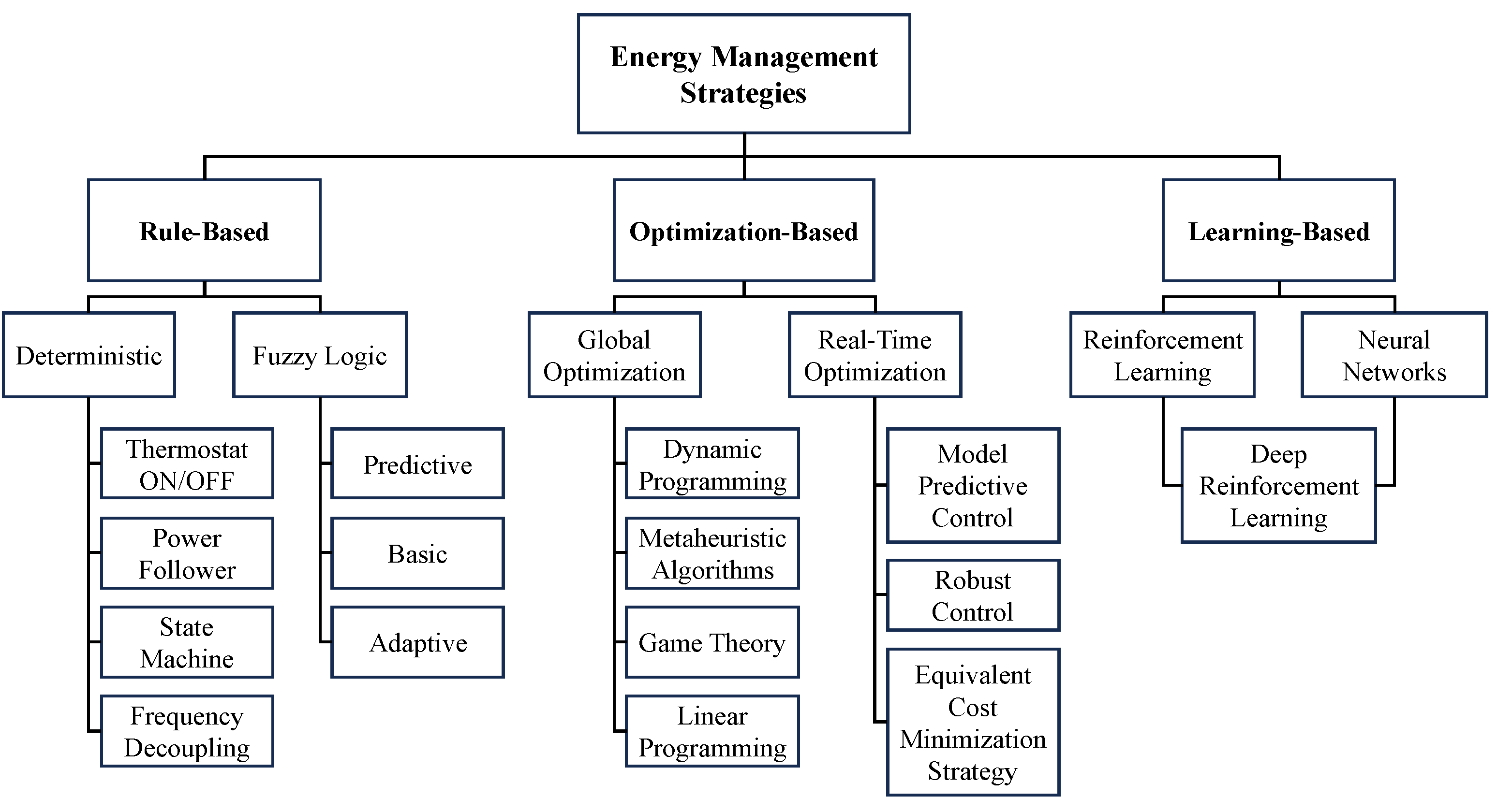
Three main categories can be identified regarding EMS approaches: rule-based, optimization-based and learning-based control strategies [7]. This classification and the subsequent possible control strategies of each category are depicted in Figure 1.

Figure 1.
Classification of strategies for energy management systems.
1.1.1. Rule-Based EMSs
Rule-based control strategies represent a heuristic approach that relies on intuition and human expertise to establish a set of knowledge-based rules dictating the behavior of the energy management controller. This might be accomplished using deterministic or fuzzy-logic strategies [12].
1.1.2. Optimization-Based EMSs
Control strategies based on optimization primarily involve optimizing a cost function that represents the trade-off between efficiency, critical component degradation and emissions over a drive cycle, aiming for optimal performance [13]. This might be achieved using mathematical algorithms and methods such as dynamic programming (DP), model predictive control (MPC), etc. [14].
1.1.3. Learning-Based EMSs
As artificial intelligence (AI) and computational technologies advance rapidly, learning-based control strategies have been increasingly applied in the study of EMSs in recent years. In addition to achieving satisfactory optimization results, learning-based EMSs exhibit significant potential for real-time implementation, serving as a viable compromise between rule-based and optimization-based EMSs [15].
The selection and design of these EMSs pose a non-trivial challenge, given that each category has their own benefits and drawbacks. For instance, optimization-based EMSs may excel in seeking a global optimum solution, but their substantial computational costs pose a significant drawback for real-time energy management applications. In addition, rule-based EMSs, with a greater aptitude for real-time implementation, heavily rely on human expertise and intuition, potentially leading to critical design errors [14]. Moreover, learning-based EMSs demand extensive driving-related training datasets and prolonged training times, posing potential hindrances to their real-time application [15].
1.2. Proposed Control Strategy
DP EMSs have been recognized for their effectiveness in addressing the problem at hand [16]. Based on the principle of Bellman’s optimality, which asserts that an optimal decision can be derived by decomposing the primary problem into various subproblems, ultimately yielding the optimal control trajectory to minimize a specific cost function [17]. However, due to the high computational burden of DP and the fact that the solution is exclusively optimal for a specific driving cycle, making online implementation significantly challenging, DP is primarily employed as a useful benchmark solution for the analysis, adjustment and evaluation of alternative control strategies [18].
Given this outlook, the EMS referred to as adaptive neuro fuzzy inference system (ANFIS) [19] has been recognized as the designated and computationally feasible approach for future FCHEV implementation once the validation workflow is completed, commencing with the performance evaluation on a simulation platform, and ending with a hardware in the loop (HiL) result assessment. Fuzzy logic has already been proven as a viable strategy to effectively reduce fuel consumption in HEVs [20,21,22]. However, as previously mentioned, rule-based EMSs such as fuzzy logic rely on human expertise and proper understanding of the system under consideration, which may present an obstacle for the optimal definition of the rules and membership functions that compose a controller of this nature [23]. ANFIS controllers overcome this hindrances by extending the conventional fuzzy inference system through an integration with artificial neural networks (ANNs), where the initial phase of such a system involves training a conventional fuzzy framework by a learning algorithm, which aids in the definition of the linguistic rule base and membership functions intrinsic to fuzzy logic [24]. Similar to any other learning algorithm, ANFIS requires training data, which, in this case, stems from offline simulations performed using the DP strategy. In this manner, the controller will be able to emulate the operation suggested by DP in real-time, achieving optimal outcomes aligned with the proposed targets of reducing fuel consumption and therefore extending FC and battery lifespans. With the integration of this methodology, a controller that effectively combines the three main categories of EMSs is proposed. This integration resolves the drawbacks that may arise from applying each strategy separately, thereby creating a robust and efficient system capable of delivering optimal performance in real-world applications. This research aims to demonstrate that the proposed DP-based ANFIS EMS can efficiently manage energy in FCHEVs while remaining computationally practical for real-time application. By testing the system across various driving cycles in a simulation platform and validating its performance through HiL testing, the study sets a benchmark for future EMS designs seeking fuel consumption and computational efficiency optimization in dynamic environments.
Design configuration, component sizing and power management methods have been remarked earlier in this paper as the three primary considerations regarding FCHEVs. This paper can be considered a continuation to the component sizing proposal addressed in [25] and an extension of [26] in which the methodology to be followed for the creation of an ANFIS controller was showcased. The article is organized as follows: The use case and simulation platform is showcased in Section 2, as well as the HiL equipment, where further testing will be conducted. The simulation results and discussion is provided in Section 3 and Section 4, followed by the conclusions and future scope in Section 5.
2. Materials and Methods
2.1. Use Case Definition
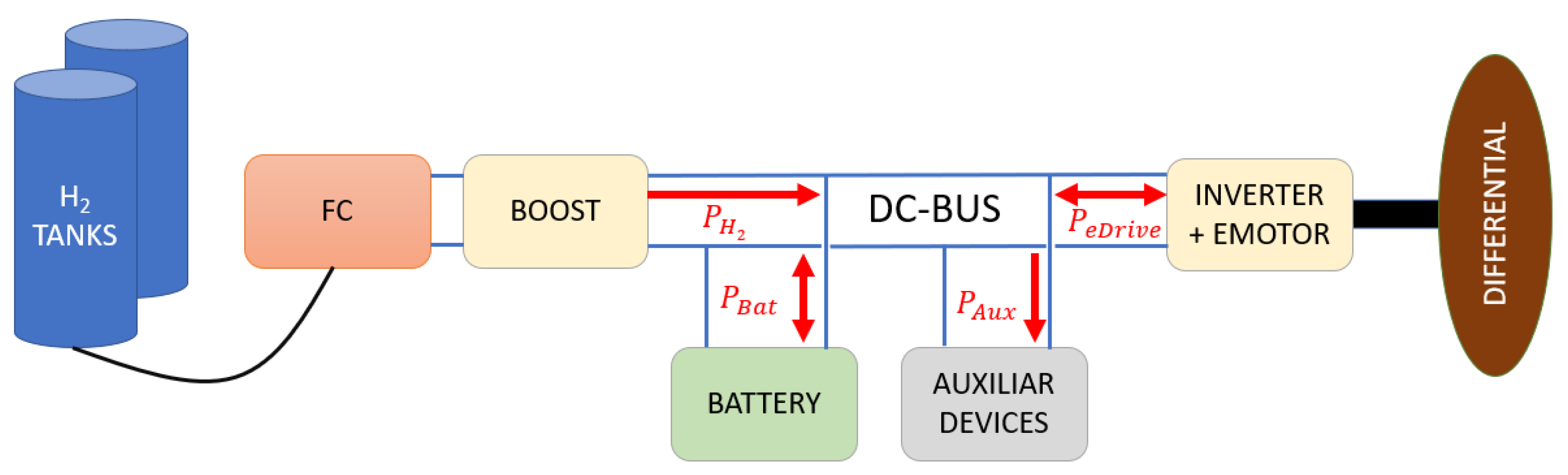
Serial FCHEVs typically exhibit the configuration depicted in Figure 2. Power sources include a battery and a FC, both linked to a DC-BUS. Hydrogen is stored in tanks and directed to the FC for electricity generation. A buck/boost converter is employed to adjust the voltage to match the one imposed by the battery, before delivering the power to the DC-BUS. The total power (in watts) available in the DC-BUS comprises the sum of the power supplied by both the FC system and the battery. This power is consumed by auxiliary devices, as well as by the inverter and motor for propelling the subject vehicle, as shown in Equation (1). In addition, the electric motor (EM) has the ability to function as a generator during regenerative braking, recovering kinetic energy and channeling it into the battery to extend the vehicle’s operational range:
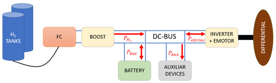
Figure 2.
Serial FCHEV layout.
2.1.1. Battery
Table 1 shows the specifications of the FCHEV battery. The capacity of the battery must be estimated depending on the energy (kWh) and nominal voltage (V) of the battery:
with this value, the SoC can be calculated as:
where Ts (s) is the discretization time of the model, In (A) is the actual current feed or absorbed by the battery, SoCn (%) is the actual SoC and QBat (Ah) the capacity of the battery.

Table 1.
Basic specifications of the battery.
Once the actual SoC is determined, the corresponding voltage value can be derived from the SoC–voltage curve. Using the battery C-rates, the maximum charge and discharge currents can be calculated, which are used for the determination of the battery’s maximum charge and discharge power. These values are critical for the hybrid control strategy.
In real vehicle applications, battery SoC might be measured via non-destructive techniques such as ultrasonic reflection waves, as reported in [27], for rapid SoC detection.
2.1.2. Fuel Cell
As previously mentioned, a FC is a device in charge of generating power by a chemical reaction between hydrogen and oxygen. With a maximum power of 100 kW, current-efficiency and current-voltage curves are implemented in the model, which allows for the definition of the operating point at each time step. In this case, information about the net power consumption is available and has also been implemented in order to compute the hydrogen consumption during vehicle operation. If these values were to be unknown, a typical mean value for total consumption of 33.33 kWh/kg can be assumed [28].
where represents the net H2 consumption ratio in kWh per kg, computed at each time step via a FC current-consumption lookup table. Un (V) and In (A) are FC voltage and current at time interval n, respectively. Ts (s), the time-step of the simulation, has been set to 100 ms.
The storage tanks have also been modeled for the remaining H2 management. The weight of these storage tanks has been considered as an input of the total weight of the vehicle. Given that the accumulated consumption is known, calculating the residual hydrogen is straightforward.
Nevertheless, in order to accurately assess the total H2 consumption for the EMSs analyzed in this research, thus enabling to examine the improvement of the efficiency of the FCHEV, a total battery recharge will be assumed to be performed at the end of each of the drive cycles. This recharge will be carried out by means of the FC exclusively, ignoring alternative methods of recharging the battery, such as regenerative braking. The rationale behind this approach is that depending on the applied EMS, the battery final SoC value will differ as the FC use rate varies, so forcing the battery to reach a common final SoC value for each of the drive cycles will aid in the calculation of total H2 consumption.
where EBat (kWh) is the battery energy. In this final recharge process, the value of has been established at the typical mean value of 33.33 kWh per kilogram of H2 in an effort to ensure greater consistency in the calculation of this total consumption for all approaches and speed profiles.
2.1.3. Drive Cycles
With the aim of ensuring that the battery and FC power of the subject HDV can effectively function across different route and load conditions, some generic use case scenarios will be simulated and analyzed. The subject HDV performs a daily refuse collection route, covering a maximum distance of 155 km around the city of Madrid (Spain). The following itineraries have been identified for performance assessment, which are depicted in Figure 3:
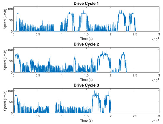
Figure 3.
Speed profiles of the considered itineraries.
- Itinerary 1: The usual 155 km long route;
- Itinerary 2: An alternative 155 km long route;
- Itinerary 3: A shorter 97 km long route with the truck heavily loaded.
Additionally, some dynamic requirements and constraints have been devised for this HDV. Conditions that will be evaluated to ensure the capability of overcoming challenging scenarios that may be encountered by the vehicle on alternate routes from the drive cycles subjected to simulation. The different energy and peak total power consumption can be derived from the suggested routes. The combination of this data and the information extracted from the dynamic requirements, makes the calculation of the maximum torque and power to be supplied possible.
2.2. Simulation Platform
A simulation platform encompassing all FCHEV models and controllers has been developed in MATLAB/Simulink 2023a, with a sample time of 100 ms. A longitudinal driver model and vehicle chassis model, which gives feedback to the driver is additionally included in the platform, with the aim of executing longitudinal cycles. The Dynacar Lite modelling approach has been chosen for this platform, a forward modelling formulation with a simplified vehicle model which only involves longitudinal dynamics for fast solving time, thanks to its ease of tuning and computational efficiency. Dynacar Lite is part of a vehicle dynamics simulation tool developed by Tecnalia R&I called Dynacar [29]. This approach is based on a point-mass model in charge of computing the traction forces, longitudinal aerodynamics, rolling forces and slope forces:
It is important to highlight that as in every forward model, the traction-brake torques serve as inputs, while the longitudinal acceleration of the truck constitutes the output. For slope calculation, a distance-slope lookup table for each route is employed. The mass load of the vehicle is crucial for the model, as it varies based on route, distance and day. For each of the use case drive cycles, the changing mass load has been documented and incorporated into a distance-mass lookup table. Consulting the historical database for typical mass loads of the applied drive cycles is recommended, if available.
The overall structure of the simulation platform is depicted in Figure 4. Special focus will be directed towards the so-called hybrid control unit (HCU), which computes a traction or regenerative torque setpoint based on driver commands, maximum available power in the battery and FC. This setpoint is then converted into the required power, accounting for the consumption of the auxiliary devices. The power to be generated by each of the power sources is independently determined, subject to the specified hybridization strategy. This unit will therefore act as the starting point for the implementation of the proposed EMS, featuring the ability to tailor its configuration to our preferences and facilitating comprehensive assessments, including efficiency comparisons and performance evaluations.
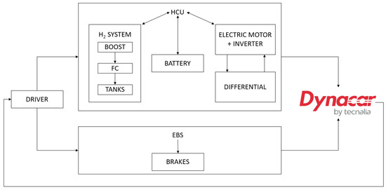
Figure 4.
Simulation platform structure overview.
A longitudinal driver is also employed, converting each of the drive cycles into a speed–time and elevation–distance longitudinal cycle to estimate power consumption. As a result, the driver must adhere to a time–velocity curve. The longitudinal control is then managed via a PID controller in conjunction with a feedfoward mechanism.
The electric brake system (EBS) is another significant model of the FCHEV, which calculates the mechanical braking torque required and the amount of braking torque to be regenerated by the EM, taking into account the constraints of the EM and regeneration rules.
2.3. Baseline Control Strategy
The EMS currently defined on the HDV subject of study is a rule-based, deterministic generic thermostat or ON/OFF strategy, commonly employed in Serial HEVs. This approach involves sustaining the battery state of charge (SoC) within an upper and lower threshold. When the SoC falls below the lower limit, the battery is charged at a constant power supplied by the FC. Once the upper limit is reached, charging ceases, transitioning the FC to an idle operating point. Adjusting this threshold will have an impact in fuel consumption, influencing the duration of FC operation. The baseline strategy settles this threshold between 45% and 50% of the battery SoC, with the aim of keeping the battery operative in its medium capacity and ensuring the possibility of kinetic energy absorption from the wheel during vehicle braking. Nonetheless, this EMS is proven less than ideal in fulfilling the objectives of optimizing energy distribution between power sources, reducing fuel consumption, extending the lifespan of both FC and battery while enhancing overall vehicle efficiency and contributing to the overall mitigation of GHG emissions of the HDV. The aforementioned strategy ignores dynamic scenarios that may arise during vehicle operation, such as a driver-initiated kick-down, translating into a sudden surge in energy demand, where an immediate torque application may become essential. In such situations, the battery delivers the necessary power, constrained by its charge and discharge currents. As a result, FCHEVs must always include a battery, even if it is of minimal capacity, to accommodate rapid transients that the FC is unable to manage.
2.4. Dynamic Programming
As stated earlier, the DP global optimization algorithm excels in computing the optimal control trajectory in highly non-linear dynamic systems similar to the problem at hand. The DynaProg [30] open source MATLAB toolbox has been employed for solving this finite horizon multi-stage deterministic decision problem, for which a cost function must be defined:
In this case, only the H2 consumption (kg) has been considered. However, formulating a more complex cost function with additional inputs and assigning varying weight values according to the desired optimization criteria would be advantageous, as this approach would enable the incorporation of other dynamic factors that might be of interest such as FC degradation or ownership cost, creating a complete cost function that establishes a compromise between both H2 consumption reduction and FC lifespan improvement.
The control variable is a crucial component in DP as it represents the variable for which the algorithm determines the optimal control trajectory. This sequence specifies the values that the control variables should assume at each time step to minimize the previously defined cost function. In this context, the FC current has been selected as the control variable, constrained within the operational limits of the FC.
Additionally, a state variable is essential in this approach, as its temporal variation affects the terminal cost. The battery SoC has been designated as the state variable, initialized at 90% and constrained to a final range between 45% and 50%, in an effort to mirror the final SoC value of the baseline EMS. It should also be noted that the battery shall be maintained at an adequate charge level at all times. In order to maximise its operational lifespan, it should never drop below 20%. This constraint has likewise been implemented to the DP algorithm.
2.5. ANFIS
The ANFIS methodology starts from an initial fuzzy inference system (FIS), which is then modified using training data extracted from another optimization method, DP in this case. The fuzzy logic toolbox included in MATLAB 2023a streamlines this process by enabling the generation of a preliminary FIS from existing data, making this initial step relatively straightforward. A DP optimization run will be conducted to obtain the base dataset, which will then be processed for automatic initial FIS generation via a fuzzy C-means clustering algorithm. As a result, a preliminary Sugeno-type FIS will be generated, as ANFIS optimization in MATLAB is only applicable to Sugeno-type fuzzy systems. The inputs/outputs selected for this FIS are the following:
- Input 1: Battery SoC;
- Input 2: EM Power;
- Output: FC Power.
Once the initial FIS structure is achieved, the next step consists of training the ANFIS algorithm to be able to replicate the results obtained via DP. The training process aims to adjust the membership functions and rules originally proposed by the clustering algorithm. For this process, 80% of the data generated by the DP optimization has been used, while the remaining 20% test the effectiveness of the learning process.
The ANFIS training is conducted with the aid of an optimization algorithm. The least squares estimation with backpropagation algorithm has been selected for its superior performance based on various tests performed with the different available optimization methods. This algorithm tunes the FIS parameters using a combination of backpropagation (for the parameters associated with the input membership functions), and least squares regression (for the parameters associated with the output membership functions). A total of 300 epochs will be executed, resulting in a FIS that will be further validated with the test dataset and the system validation tool of the fuzzy logic toolbox before final implementation on the simulation platform.
2.6. Hardware in the Loop Performance Evaluation
HiL is a sophisticated simulation methodology employed in the development and assessment of complex process systems. This technique allows for the substitution of either the control systems or the physical components of a system with real-time simulation.
Real-time simulation is crucial due to the dependency of system solving speed on the complexity of the mathematical model in offline simulations. In such scenarios, the goal is to achieve results in the least amount of time possible. However, in real-time simulation, computational accuracy hinges not only on the detailed dynamic representation of the system but also on the execution time. Real-time models operate at the same rate as the actual physical system, having to accurately compute solutions within a time-step shorter than the wall clock duration of that time-step. If the simulator processes are not completed within the designated fixed time-step, the real-time simulation is deemed erroneous [31].
With the purpose of assessing whether the developed EMS is computationally feasible for real-time application, simulations will be executed in a Speedgoat rapid control prototyping (RCP) machine, comparing results with offline simulations and evaluating its performance.
2.6.1. Rapid Control Prototyping
The Speedgoat Baseline-M Real-Time Target Machine will be employed for real-time simulation assessment. Table 2 provides a brief summary of the characteristics of this machine, which was primarily selected due to the straightforwardness of its integration with Simulink models with the aid of Simulink real-time environments. This integration ensures a seamless interaction between software and hardware, in contrast to other manufacturers, which often require generating C code to implement Simulink models into their hardware.
Table 2.
Speedgoat Baseline-M Real-Time Target Machine 107101 characteristics.
2.6.2. Hardware in the Loop Testing Bench
Further testing will be conducted as future work in a heavy-duty testing bench, which consists of all elements necessary for the development and testing of complete or partial propulsion systems for HDVs, including transmission elements, with the possibility of emulating battery and hydrogen FC systems. The equipment allows the measurement of mechanical and electrical quantities of traction systems under test, with the possibility of conducting testing either manually or automatically. The bench serves multiple purposes, encompassing the development of electric and hydrogen-hybrid traction systems for HDVs. Additionally, it facilitates the characterization of traction systems, conducts validation tests to assess requirement specifications, evaluates energy efficiency and autonomy, and enables the simulation of operating cycles. Table 3 showcases the available equipment of the heavy-duty testing bench:
Table 3.
Heavy-duty testing bench equipment.
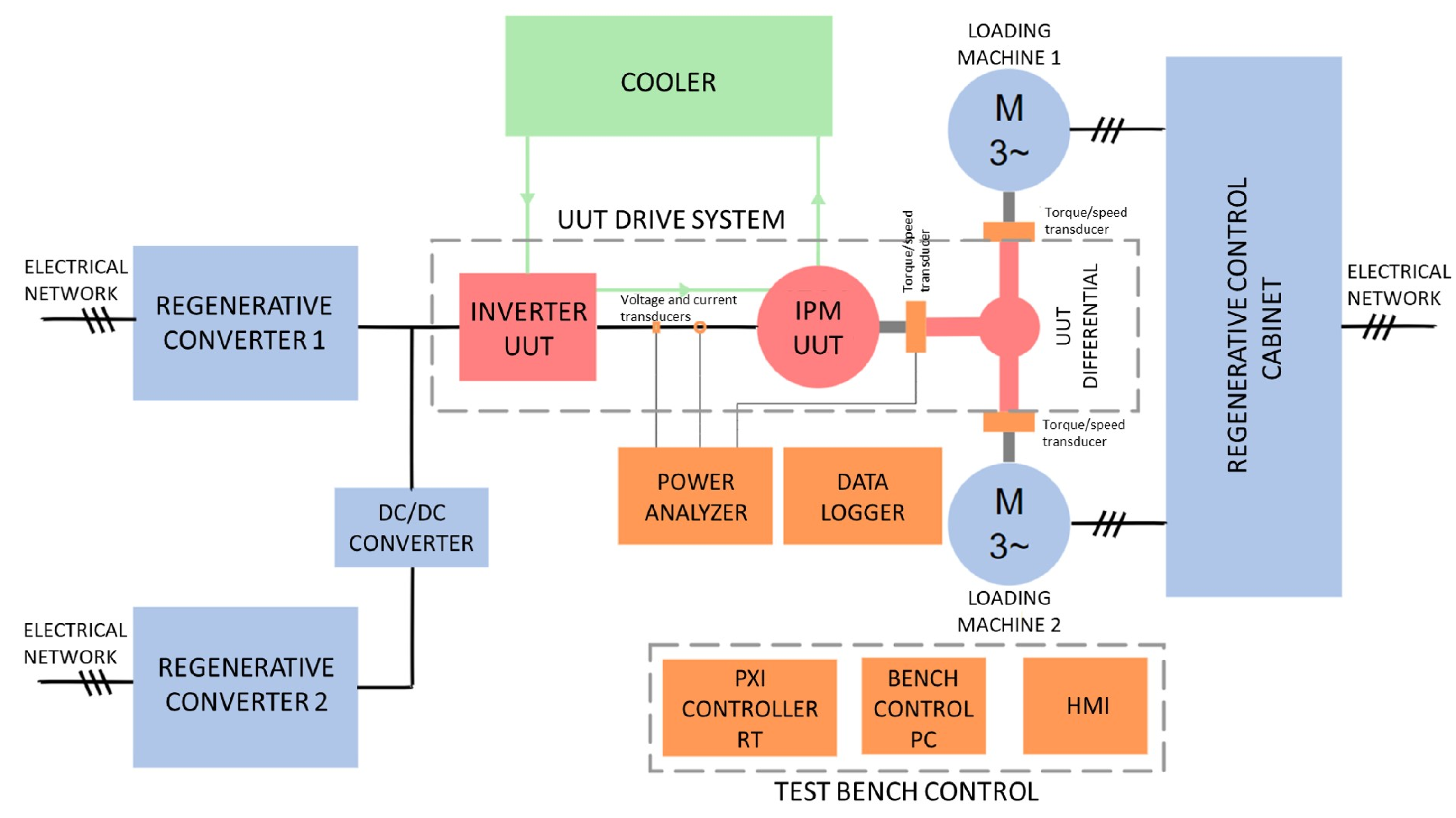
A data recording and conditioning system is also included in the bench, allowing for the connection and conditioning of a wide range of sensors and transducers employed in traction system tests. An overview of the testing bench structure and the configuration of these components can be seen in Figure 5.

Figure 5.
Heavy-duty testing bench structure overview.
3. Results
The limitation of DP algorithms to obtain the most suitable control trajectory only for the specific context in which the optimization is launched has been stated earlier in this text. The objective is to develop a controller that achieves H2 consumption savings across all potential scenarios, which is why three different drive cycles have been considered for performance evaluation. Consequently, if data obtained through DP for a specific drive cycle is used to train the ANFIS controller, it cannot be guaranteed that savings will be achieved for alternative speed profiles. Therefore, in order to account for the widest possible range of scenarios, the following approaches have been contemplated.
- ANFIS: Training is conducted using a dataset obtained from a DP optimization of Itinerary 1 (the longest and most generic speed profile) while adhering to the previously specified initial and final state variable constraints.
- ANFIS DP Full: Training is conducted using a dataset obtained through multiple DP executions of Itinerary 1, varying the initial value of the state variable from 20% to 100%, increasing it by 5% in each run, and adhering to the previously specified final state variable constraints.
- ANFIS DP All Cycles: Training is conducted using a dataset obtained through DP optimizations of every itinerary available, while adhering to the previously specified initial and final state variable constraints.
The diversity in approaches allows exploring how the developed ANFIS controller responds to different scenarios, thereby helping to identify the strategy that best meets the needs of the FCHEV.
Normalization of the training and validation data is common in learning strategies such as the one under consideration as this procedure ensure that both inputs and outputs are on the same scale, simplifying the training process and reducing the associated computational cost. Given this approach, normalization to a range from 0 to 1 has been applied to all datasets.
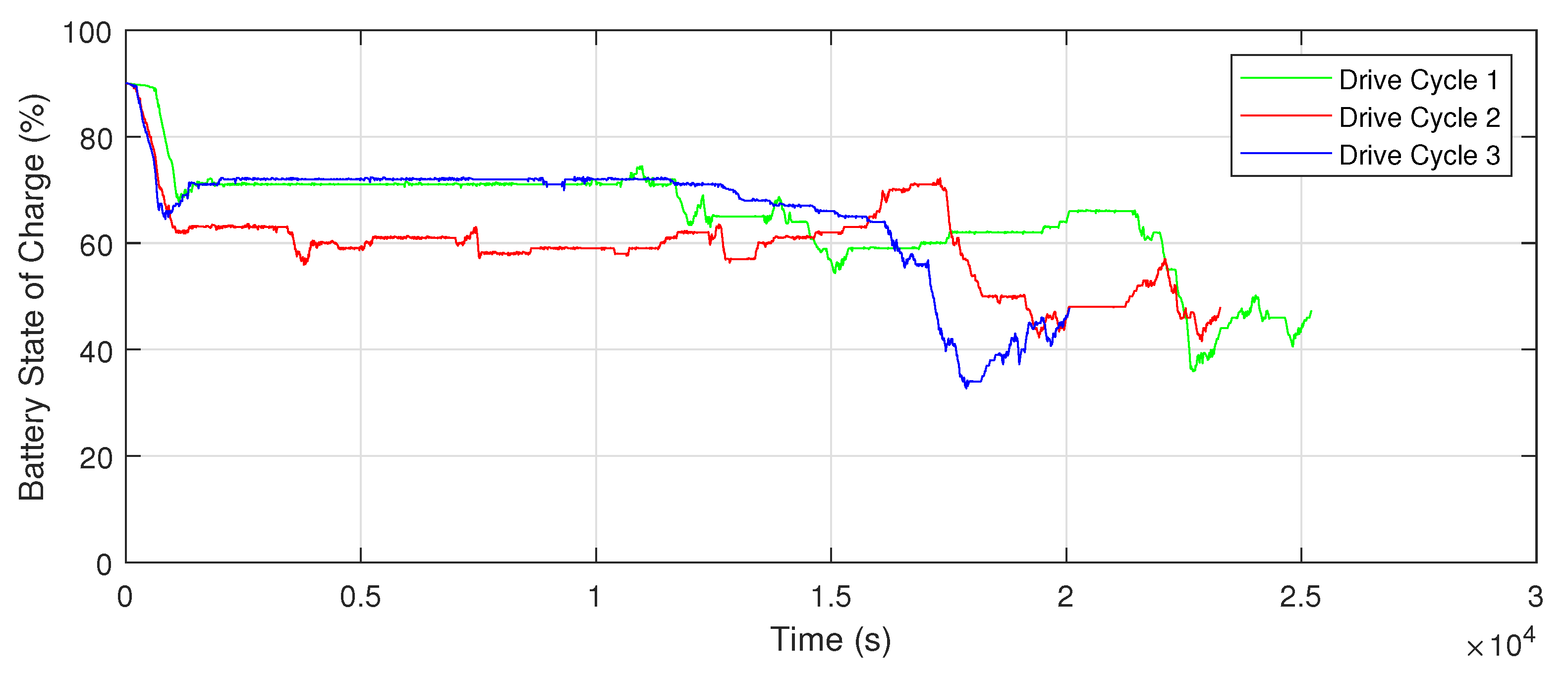
The SoC trajectory derived from DP for each of the drive cycles considered and to be reproduced by the ANFIS controller is detailed in Figure 6.
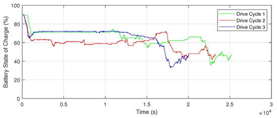
Figure 6.
DP battery SoC depletion trajectories for all drive cycles.
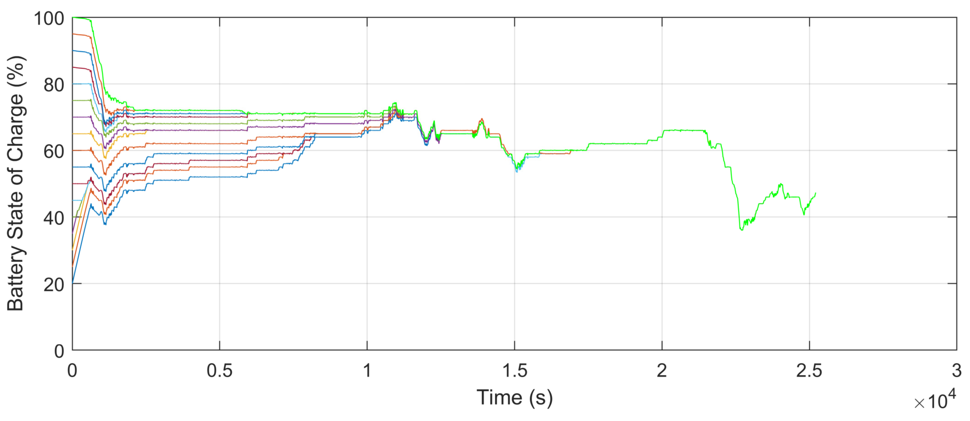
Similarly, for the DP Full approach, where different SoC trajectories were considered by increasing the initial value by 5% increments for Drive Cycle 1, the resulting outcomes are showcased in Figure 7.
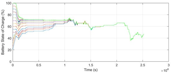
Figure 7.
DP battery SoC depletion trajectories for Drive Cycle 1 with varying initial SoC, from 20% to 100% in 5% increments.
These SoC trajectories, along with the results of the other inputs/outputs, will be used to generate the normalized training and validation datasets.
Upon completion of the training process, three distinct ANFIS controllers will be generated (one for each approach) and implemented in the FCHEV simulation platform.
3.1. ANFIS Controller Validation
The validation of the trained controllers has been conducted by comparing the target speed profiles of each driving cycle with the speed profiles obtained after implementing the ANFIS controllers in the simulation platform. Thus, the proper operation of the fuzzy logic controller will be validated as long as these speed profiles match at each point in time allowing for some degree of tolerance or imprecision due to the nature of the simulation platform and these speed profiles. The normalized root mean square error (NRMSE) has been considered for each approach and drive cycle. This is shown in Table 4, for which min–max normalization of each drive cycle has been carried out for NRMSE calculation.
Table 4.
Speed NRMSE for each of the drive cycles and EMS approaches considered.
The observed minimal NRMSE values indicate that the proposed EMS approaches successfully satisfy the target speed profiles.
3.2. Computational Efficiency Assessment
Further controller validation has been carried out evaluating the computational speed of the different EMS approaches considered. As previously mentioned, the offline nature and high computational load of DP algorithms hinder their applicability in real-time scenarios as it must recursively evaluate each potential decision point across the entire time horizon. For dynamic systems, this translates into long processing times and high memory usage which are incompatible with the fast-paced requirements of real-time operations. In contrast, ANFIS controllers offer a substantial reduction in computational demand due to their inference capabilities, allowing them to make decisions efficiently and suitable for real-world scenarios where responsiveness and adaptability are crucial for maintaining system performance.
Table 5 highlights the significant difference in computational speed between the proposed EMS approaches, showing that ANFIS controllers offer a promising middle ground with significantly lower computational times, making them viable for real-time implementation while still providing more advanced control than the baseline EMS.
Table 5.
Execution times for each of the drive cycles and EMS approaches considered.
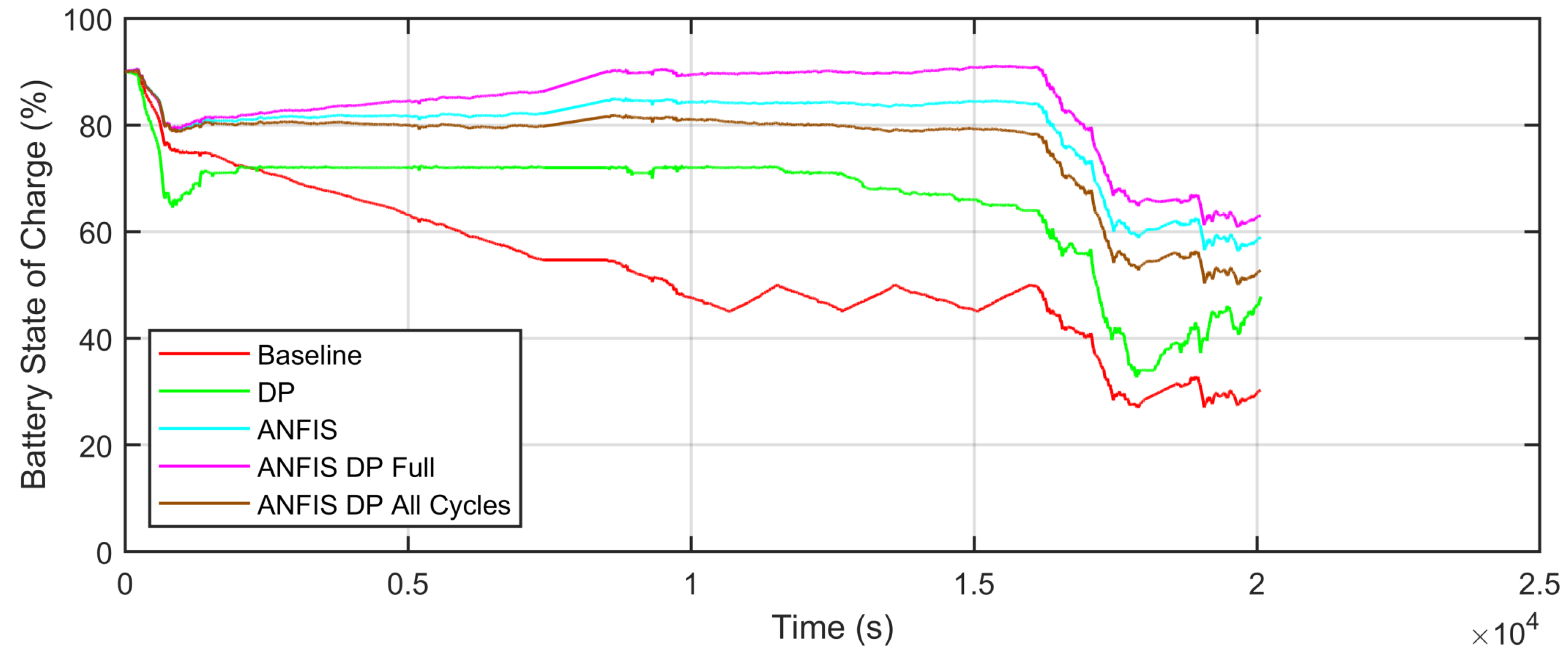
3.3. SoC Replication Capability
The main objective of implementing an alternative EMS is achieving a controller with the capability of reproducing, as closely as possible, the optimal control trajectory proposed by the DP algorithm. The evolution of the battery SoC over the specified driving cycle serves as a valuable metric for assessing the performance of the ANFIS controllers. Therefore, this SoC will be employed to evaluate the effectiveness of the various proposed approaches to replicate the power distribution suggested by DP.
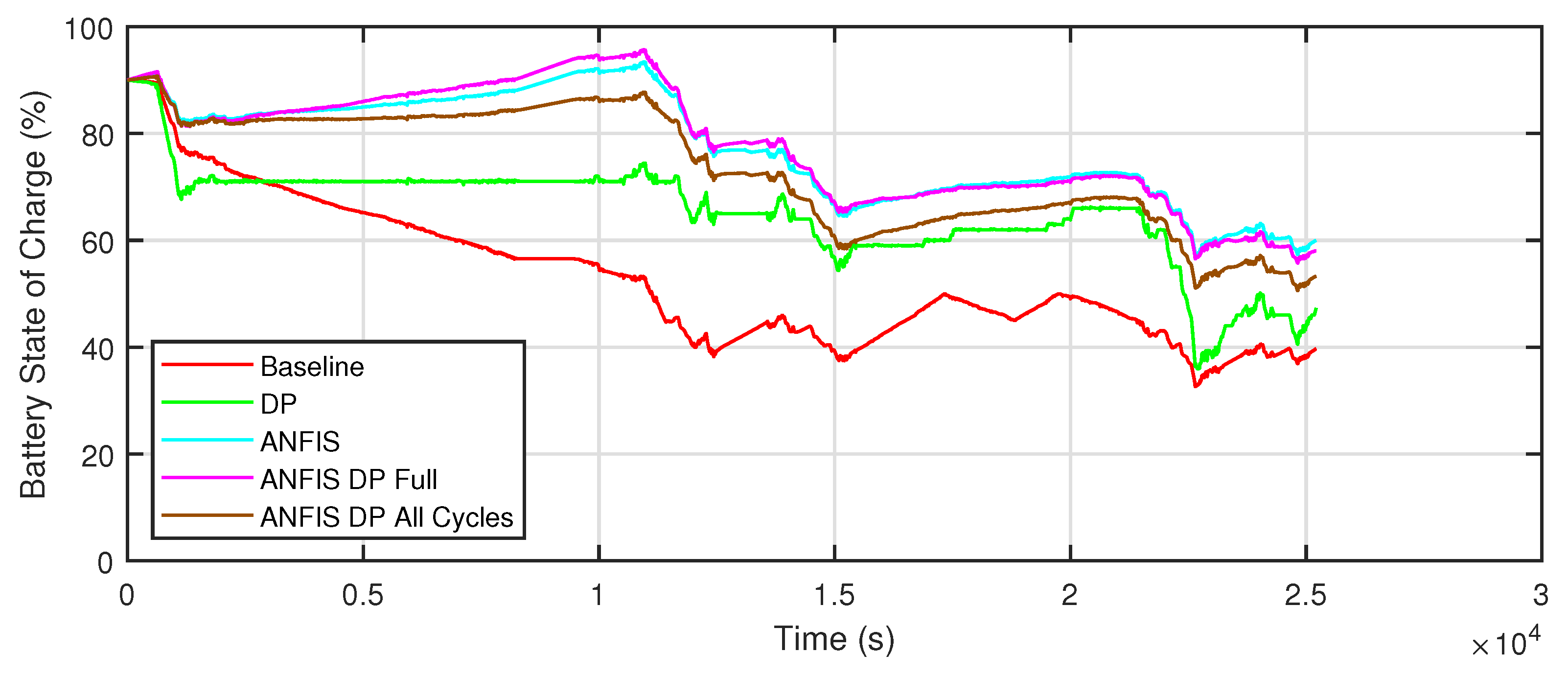
Figure 8, Figure 9 and Figure 10 show the calculated battery SoC for all approaches considered, for which data from Table 1 and Equation (3) have been applied.
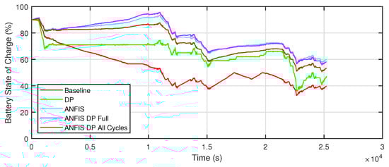
Figure 8.
Drive Cycle 1 battery SoC depletion for all EMS approaches.
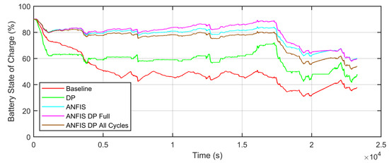
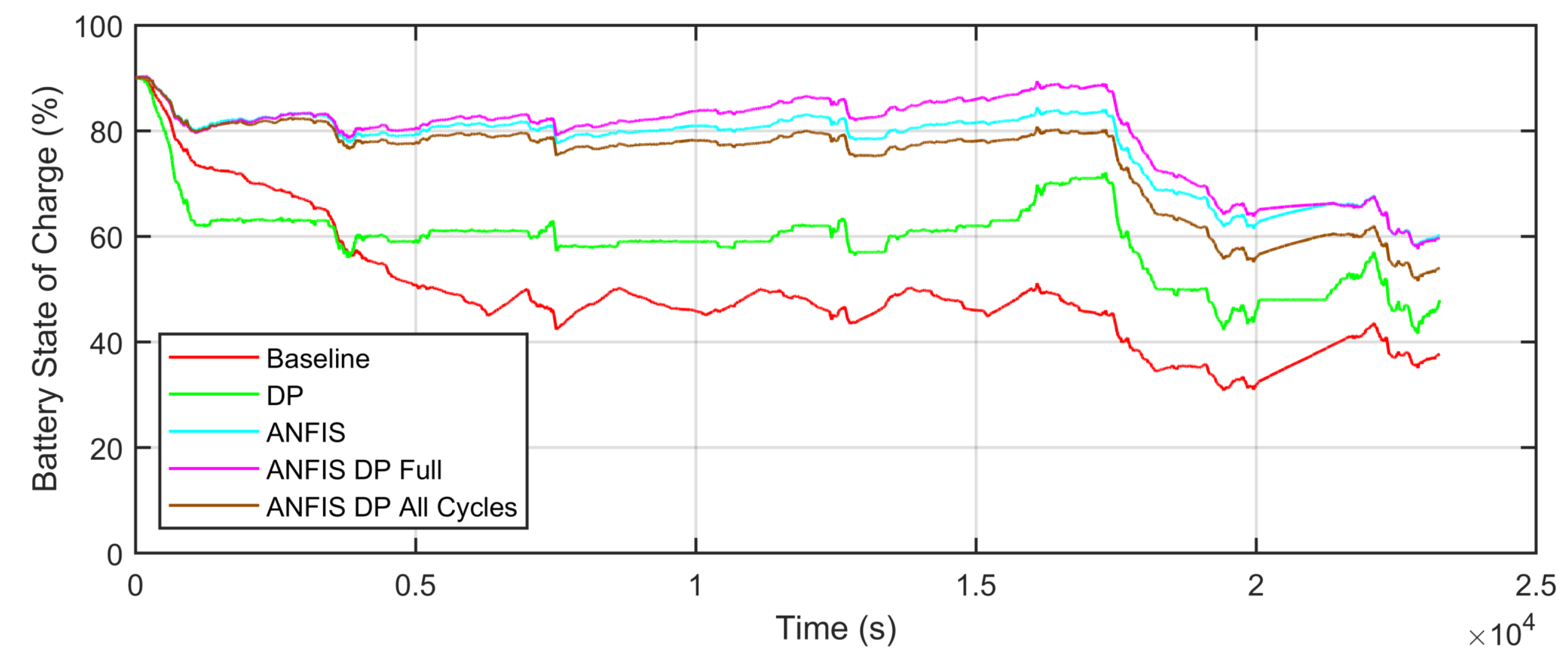
Figure 9.
Drive Cycle 2 battery SoC depletion for all EMS approaches.
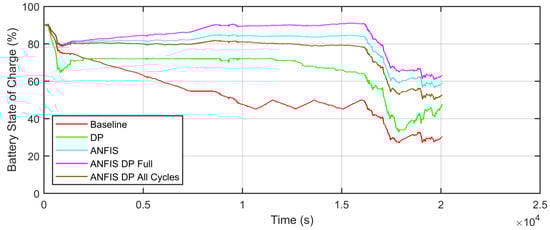
Figure 10.
Drive Cycle 3 battery SoC depletion for all EMS approaches.
The implemented EMSs successfully emulate the SoC trajectory proposed by DP to a reasonable degree, with variations depending on the considered speed profile.
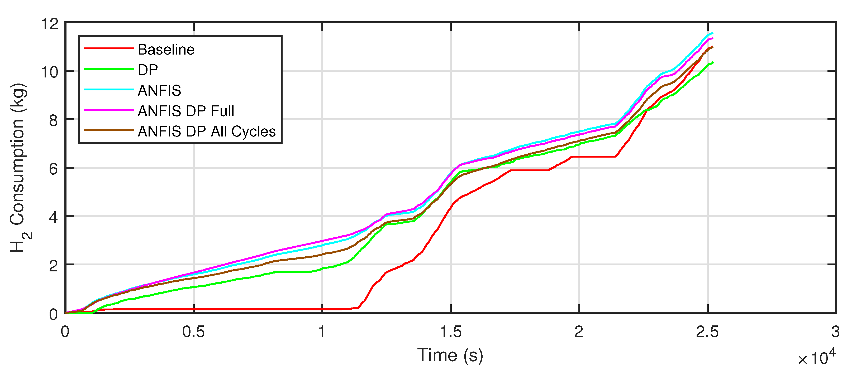
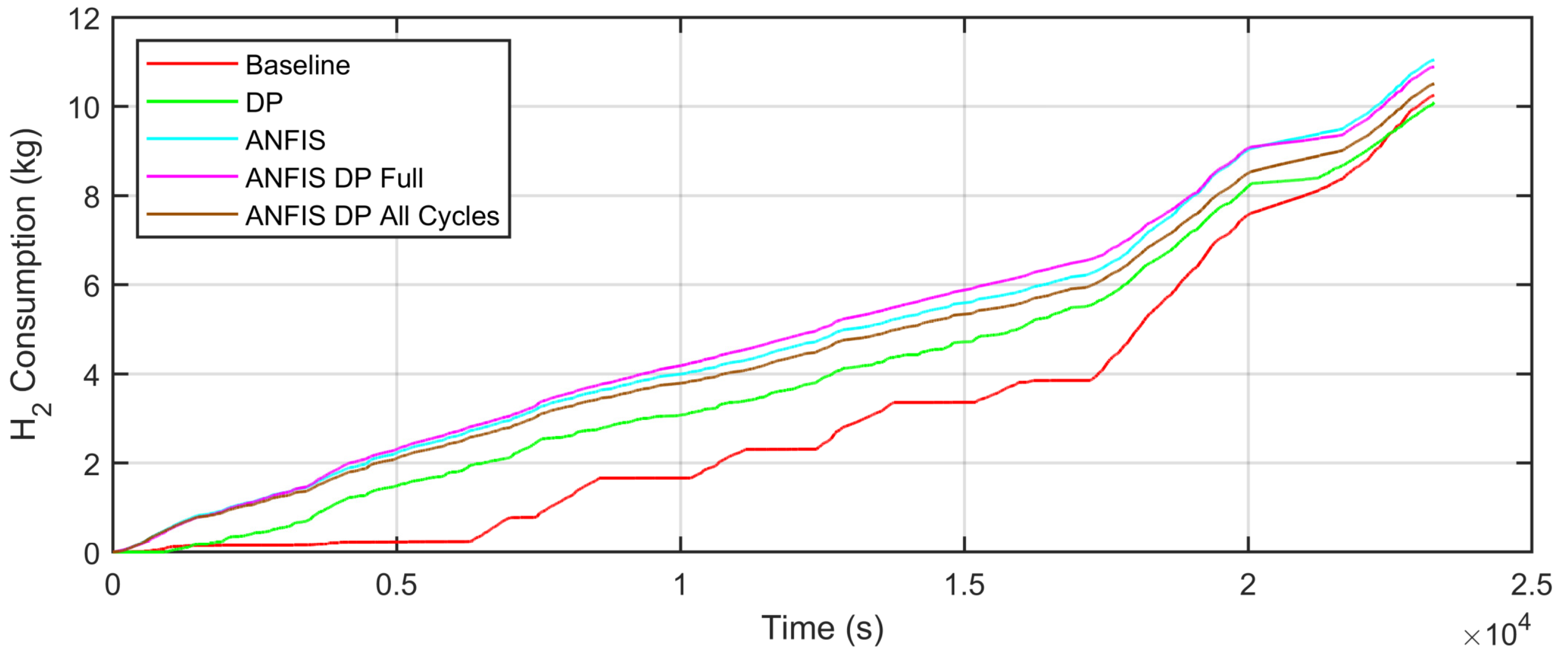
3.4. H2 Consumption Analysis
In order to thoroughly evaluate the developed approaches, a final step involving H2 consumption analysis has been conducted, with the expectation that the approaches best replicating the DP SoC trajectories will exhibit similar H2 consumption to that of DP. Figure 11, Figure 12 and Figure 13 show the evolution of H2 consumption for all EMS approaches across every drive cycle.
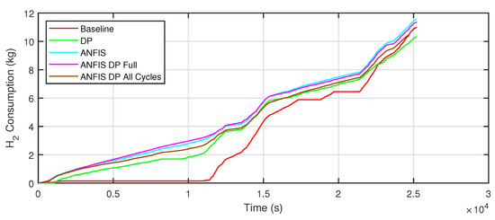
Figure 11.
Drive Cycle 1 H2 consumption for all EMS approaches.
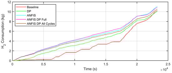
Figure 12.
Drive Cycle 2 H2 consumption for all EMS approaches.
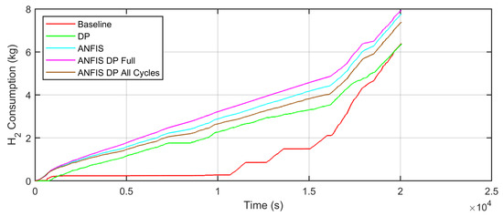
Figure 13.
Drive Cycle 3 H2 consumption for all EMS approaches.
Table 6 showcase the mass of H2 that has been consumed for all EMS approaches across every drive cycle. However, as stated in Section 2.1.2, a full recharge from the final battery SoC value to 100% will be performed, as achieving a common final SoC value mitigates the uncertainty associated with potential savings resulting from varying final SoC values. Table 7 shows the values of H2 usage after this recharge has been carried out. The calculation of total final consumption enables the determination of H2 savings relative to the baseline EMS, which are displayed in Table 8.
Table 6.
H2 consumption for each of the drive cycles and EMS approaches considered.
Table 7.
Total H2 consumption for each of the drive cycles and EMS approaches considered.
Table 8.
Total H2 consumption savings for each of the drive cycles and EMS approaches considered.
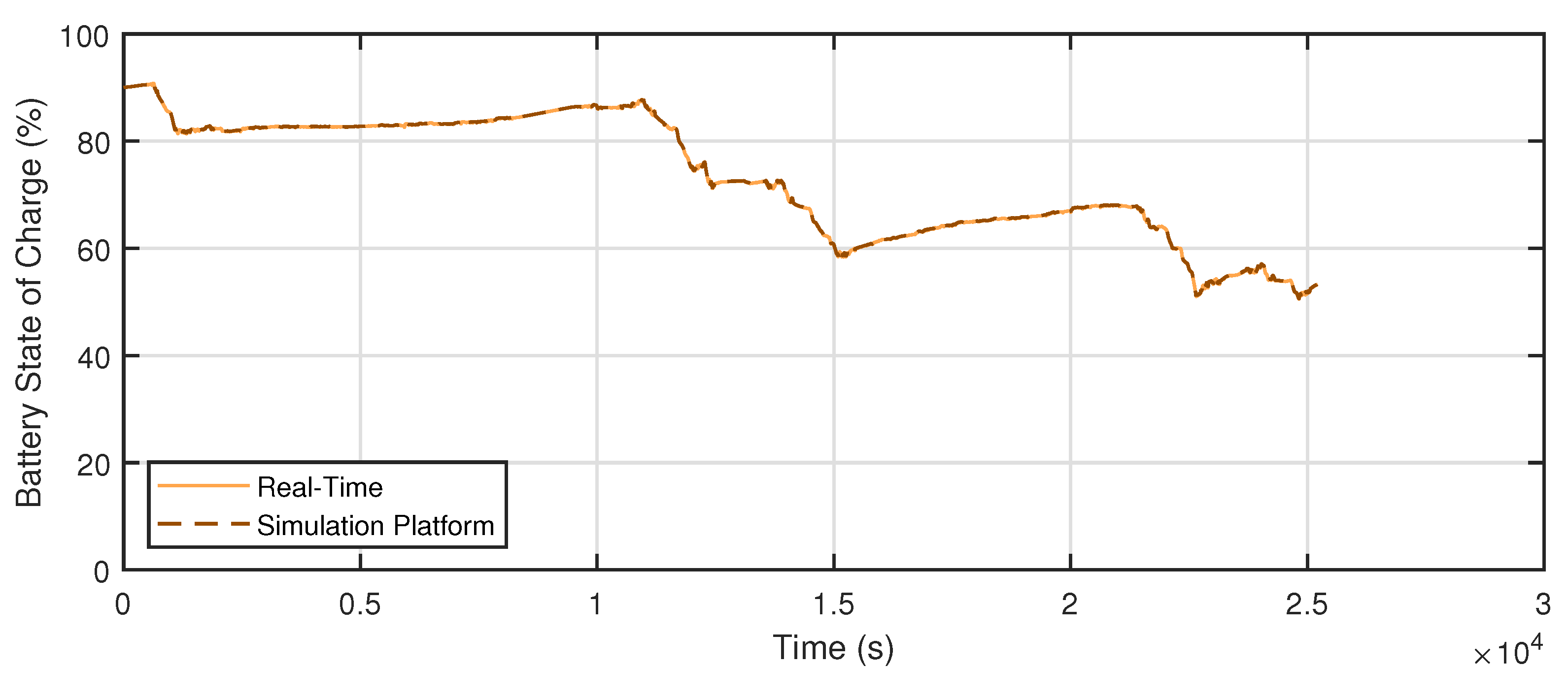
3.5. Real-Time Implementation
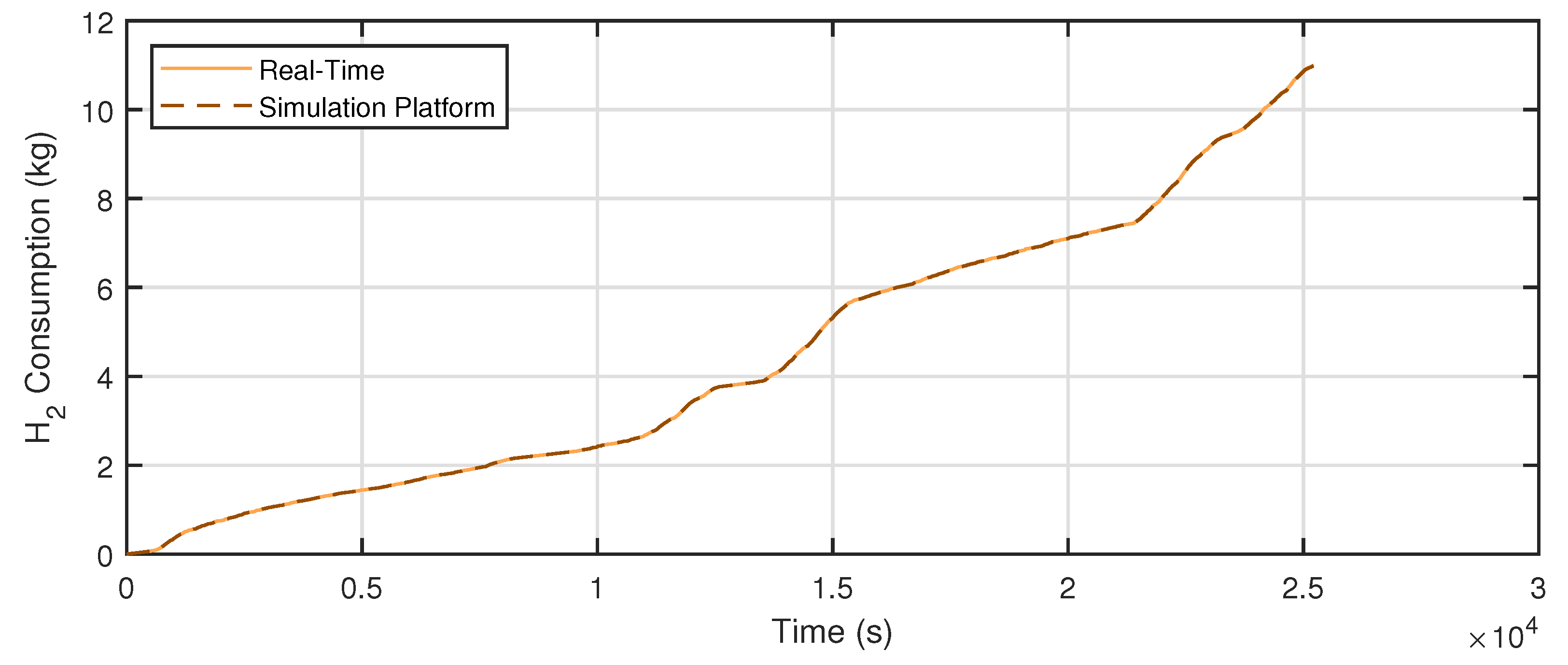
With the aim of further validate the developed approaches, all models included in the simulation platform have been deployed on a Speedgoat RCP machine, followed by the execution of Drive Cycle 1 with the objective of assessing its ability to operate in real-time, as mentioned in Section 2.6. The controller chosen for this performance evaluation is the ANFIS DP All Cycles approach for its ability to better reproduce the results of DP. The real-time experimental results are given in Figure 14 and Figure 15. While Table 9 illustrates the numerical differences between the simulation platform and real-time results, including a comparison between the execution time of the different platforms, which is essential for controller validation.
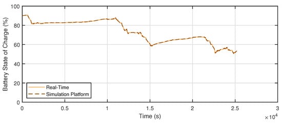
Figure 14.
Real-time performance evaluation of the selected approach (Battery SoC).
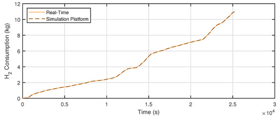
Figure 15.
Real-time performance evaluation of the selected approach (H2 consumption).
Table 9.
Drive Cycle 1 result comparison between simulation platform and real-time results.
4. Discussion
This section delves into the results obtained and their comparison after the corresponding simulations for each drive cycle have been conducted in an effort to determine which EMS approach best fit the objectives, namely:
- Follow the speed profiles;
- Reproduce DP results;
- Reduce total FCHEV H2 consumption;
- Run in real-time with minimal execution time.
The reduced NRMSE values showcased in Table 4 suggest that all developed approaches have been able to follow the cycle adequately. While the introduction of an ANFIS controller might slightly hinder the ability of mirroring the driving cycles compared to the baseline EMS, this difference is not significant enough to have a negative effect. DP achieves the lowest NRMSE results among all approaches, which is only logical due to its proven effectiveness in this regard, in addition to being an offline approach whereas the rest are online methods. It is worth noting that although the ANFIS DP All Cycles approach considered every speed profile available for the training of the ANFIS controller, it did not exhibit the highest accuracy in following the speed profiles across different driving cycles. Instead, the ANFIS DP Full approach demonstrated superior performance concerning this matter. This outcome may be attributed to the extensive dataset used for training, which comprised 17 different executions of the DP algorithm, with the possibility of achieving a more reliable approximation of the solution proposed by DP.
The execution times showcased in Table 5 reveal clear distinctions in computational efficiency between EMS approaches. The baseline EMS, while being the fastest, is a simple rule-based method that lacks the sophisticated control of other methods. As expected, DP-based ANFIS controllers demonstrate a substantial reduction in execution time compared to DP, while still maintaining more advanced control capabilities. However, it should be noted that the conducted computational efficiency assessment is subject to the processing power of the computer on which the simulations have been performed, and actual execution times may vary depending on the hardware used. Nevertheless, the relative differences in execution times between the approaches are likely to remain consistent across different computational setups.
Since DP is considered one of the most adequate options for reducing the specified cost function (H2 usage, in this case), achieving an ANFIS controller that most reliably reproduces the result of DP is ideal, as it will contribute to the minimization of H2 consumption of the FCHEV. Analyzing Figure 8, Figure 9 and Figure 10, where the battery SoC curve is represented for all cycles and each proposed approach, it is evident that ANFIS DP All Cycles is the most effective EMS in replicating the trajectory proposed by DP across all scenarios. Conversely, the ANFIS DP Full strategy appears to be the least effective, although its results do not significantly differ from those of the conventional ANFIS approach, suggesting that obtaining a much larger training dataset has minimal impact on this matter. The ANFIS approach, although trained with data obtained from the first drive cycle, has been capable, to an extent, of replicating the DP trajectory, further supporting this hypothesis. However, ANFIS DP Full is likely to have positive effects in the event of initial SoC value modification.
Be that as it may, it is evident that the SoC profile obtained by the ANFIS models is significantly similar to that of DP, with the exception of a noticeable increase in battery consumption at the beginning of each cycle. This surge seem to correspond with a relatively high-speed section where the application of a large amount of power is presumably essential to accurately meet the speed profile. The ANFIS models appear to behave differently in this scenario, applying a more conservative battery consumption approach. The cause of this discrepancy may be attributed to differences between the MATLAB model used by DP and the Simulink model employed by ANFIS EMSs. Resolving this discrepancy would be ideal, as the best approach (ANFIS DP All Cycles) appears to achieve a very similar speed profile to that of DP throughout the rest of the cycle.
The results showcased in Table 8 clearly demonstrate that the DP algorithm achieves the maximum savings in term of H2 consumption, as anticipated. As a consequence, and as previously mentioned, the approach most similar to this method will achieve the highest H2 savings in the final application in the FCHEV. Hence, the ANFIS DP All Cycles EMS has been identified as the most effective in reducing H2 usage across all cycles, with a maximum savings amount of 5.27% in Drive Cycle 1. It should be noted that exists a clear deviation in the achieved savings compared to DP across all of the considered speed profiles, with this being more evident in Drive Cycle 3, where the differences between the ANFIS and DP trajectories reduce the savings to 1.89%. The FCHEV under study is a waste collection vehicle, and this cycle simulated the scenario in which the FCHEV was fully loaded, operating at its maximum mass. At the end of this cycle, there is a sustained increase in speed. This, combined with the increased load of the FCHEV, requires a maximum power output to propel the vehicle and, as a result, H2 usage increases significantly during this section, as shown in Figure 13. Nevertheless, the decrease in H2 consumption achieved for all drive cycles and ANFIS approaches, confirm that achieving a performance similar to DP is feasible with such an EMS.
Lastly, the real-time experimental results given in Figure 14 and Figure 15 show nearly identical performance when compared to those of the simulation platform as both plots overlap. This is further supported by Table 9, where a comparison is conducted between both simulation approaches. The mean execution time of 0.045 ms confirms the feasibility of deploying the proposed controller in real-time environments, as processes are completed within the designated fixed time-step of 100 ms, deeming feasible the EMS implementation in a testing bench or an FCHEV for possible future work.
5. Conclusions
The conducted research introduces a new EMS applied to a waste collection FCHEV. This strategy presents an improvement over the currently defined approach with a focus on enhancing powertrain efficiency and achieving optimal power distribution between battery and FC, reducing H2 consumption in the process. To this end, results from DP optimizations have been employed to train three different ANFIS controller approaches based on battery SoC and EM power as inputs, and FC power as the output.
In order to assess the performance of the proposed controllers, different waste collection routes have been tested and, in light of the simulation outcomes, it is fair to assert that the suggested ANFIS controllers provide a reduction in regard to the values of total consumption in comparison with the baseline control strategy, although the extent of this reduction varies depending on the characteristics of the tested drive cycle. Attaining savings of 5.27%, 4.39% and 1.89% for each speed profile, respectively, the approach based on generating a dataset encompassing DP results across all drive cycles has been proven to be the most effective in H2 usage reduction, which has been later executed in a real-time Speedgoat machine to validate its performance in such environments.
The ensuing phase in further validating the effectiveness of such an approach involves deploying the most efficient ANFIS controller in a heavy-duty testing bench to accurately test its performance under simulated real-world conditions, assessing its robustness, reliability and response to various operational scenarios. This testing process ensures that the controller meets all necessary performance criteria and is well-prepared for ensuing integration in an actual FCHEV environment.
Author Contributions
Conceptualization, I.V.M., Á.G.-B. and A.A.T.; methodology, Á.G.-B.; software, Á.G.-B. and A.A.T.; validation, I.V.M., E.Z.G. and J.M.L.-G.; formal analysis, Á.G.-B.; investigation, Á.G.-B.; resources, I.V.M.; data curation, Á.G.-B.; writing—original draft preparation, Á.G.-B.; writing—review and editing, Á.G.-B.; visualization, Á.G.-B.; supervision, I.V.M. and E.Z.G.; project administration, I.V.M.; funding acquisition, I.V.M. and E.Z.G. All authors have read and agreed to the published version of the manuscript.
Funding
The present work is supported by the ERABIL+ and Deepbask projects, funded by the Department of Industry of the Basque Government through the Collaborative Research Grants Programme Elkartek under grant agreements KK-2023/00069 and KK-2024/00069, respectively.
Data Availability Statement
The data presented in this study are available on request from the corresponding author.
Conflicts of Interest
Authors Álvaro Gómez-Barroso, Asier Alonso Tejeda and Iban Vicente Makazaga were employed by the company Tecnalia Research & Innovation. The remaining authors declare that the research was conducted in the absence of any commercial or financial relationships that could be construed as a potential conflict of interest.
Abbreviations
The following abbreviations are used in this manuscript:
| GHG | Greenhouse Gases |
| ICE | Internal Combustion Engine |
| HDV | Heavy-Duty Vehicle |
| HEV | Hybrid Electric Vehicle |
| FCHEV | Fuel Cell Hybrid Electric Vehicle |
| BEV | Battery Electric Vehicle |
| ESS | Energy Storage System |
| FC | Fuel Cell |
| EMS | Energy Management System |
| DP | Dynamic Programming |
| MPC | Model Predictive Control |
| AI | Artificial Intelligence |
| SoC | State of Charge |
| ANFIS | Adaptive Neuro Fuzzy Inference System |
| HiL | Hardware in the Loop |
| ANN | Artificial Neural Network |
| EM | Electric Motor |
| HCU | Hybrid Control Unit |
| EBS | Electric Brake System |
| FIS | Fuzzy Inference System |
| RCP | Rapid Control Prototyping |
| NRMSE | Normalized Root Mean Square Error |
References
- McKinsey Global Institute. The Net-Zero Transition, What It Would Cost, What It Could Bring; McKinsey & Company: New York, NY, USA, 2022; pp. 124–128. [Google Scholar]
- European Parliament & Council. Regulation (EU) 2019/1242 of the European Parliament and of the Council of 20 June 2019 Setting CO2 Emission Performance Standards for New Heavy-Duty Vehicles and amending Regulations (EC) No 595/2009 and (EU) 2018/956 of the European Parliament and of the Council and Council Directive 96/53/EC. OJ L 198. 2019, pp. 202–240. Available online: http://data.europa.eu/eli/reg/2019/1242/2019-07-25 (accessed on 3 January 2024).
- International Energy Agency. Global Fuel Economy Initiative; IEA: Paris, France, 2021; pp. 44–49. [Google Scholar]
- Delgado, O.; Rodríguez, F.; Muncrief, R. Fuel Efficiency Technology in European Heavy-Duty Vehicles: Baseline and Potential for the 2020–2030 Time Frame; International Council on Clean Transportation: Washington, DC, USA, 2017; p. 2. [Google Scholar]
- Sabri, M.; Danapalasingam, K.; Rahmat, M. A Review on Hybrid Electric Vehicles Architecture and Energy Management Strategies. Renew. Sustain. Energy Rev. 2016, 53, 1433–1442. [Google Scholar] [CrossRef]
- Marzougui, H.; Amari, M.; Kadri, A.; Bacha, F. Energy Management of Fuel Cell/Battery/Ultracapacitor in Electrical Hybrid Vehicle. Int. J. Hydrogen Energy 2016, 42, 8857–8869. [Google Scholar] [CrossRef]
- Ehsani, M.; Singh, K.; Bansal, H.; Mehrjardi, R. State of the Art and Trends in Electric and Hybrid Electric Vehicles. Proc. IEEE 2021, 109, 967–984. [Google Scholar] [CrossRef]
- González-Gonzalez, A.; López-Guede, J.M. Hydrogen Station Design in A Scenario of Hydrogen-Powered Heavy-Duty Fleets. In Proceedings of the 12th European Conference on Renewable Energy Systems (ECRES 2024), Mallorca, Spain, 16–17 May 2024; pp. 351–358. [Google Scholar]
- Shekhar, H.; Wei, C.; Yatim, A. Fuel Cell Hybrid Electric Vehicles: A Review on Power Conditioning Units and Topologies. Renew. Sustain. Energy Rev. 2017, 76, 268–291. [Google Scholar] [CrossRef]
- Cano, Z.; Banham, D.; Ye, S.; Hintennach, A.; Lu, J.; Fowler, M.; Chen, Z. Batteries and Fuel Cells for Emerging Electric Vehicles Markets. Nat. Energy 2018, 3, 279–289. [Google Scholar] [CrossRef]
- Tie, F.; Tan, W. A Review of Energy Sources and Energy Management System in Electric Vehicles. Renew. Sustain. Energy. Rev. 2013, 20, 82–102. [Google Scholar] [CrossRef]
- Zhou, Y.; Ravey, A.; Pera, M. A Survey on Driving Prediction Techniques for Predictive Energy Management of Plug-In Hybrid Electric Vehicles. J. Power Sources 2019, 412, 480–495. [Google Scholar] [CrossRef]
- Ettihir, K.; Boulon, L.; Agbossou, K. Optimization-Based Energy Management Strategy for a Fuel Cell/Battery Hybrid Power System. Appl. Energy 2016, 163, 142–153. [Google Scholar] [CrossRef]
- Bayindir, C.; Gözüküçük, A.; Teke, A. A Comprehensive Overview of Hybrid Electric Vehicle: Powertrain Configurations, Powertrain Control Techniques and Electronic Control Units. Energy Convers. Manag. 2011, 52, 1305–1313. [Google Scholar] [CrossRef]
- Xu, D.; Zheng, C.; Cui, Y.; Shengxiang, F.; Kim, N.; Cha, S. Recent Progess in Learning Algorithms Applied in Energy Management of Hybrid Vehicles: A Comprehensive Review. Int. J. Precis. Eng. Manuf.-Green Technol. 2023, 10, 245–267. [Google Scholar] [CrossRef]
- Wang, X.; He, H.; Sun, F.; Zhang, J. Application Study on the Dynamic Programming Algorithm for Energy Managemetn of Plug-in Hybrid Electric Vehicles. Energies 2015, 8, 3225–3244. [Google Scholar] [CrossRef]
- Bellman, R. Dynamic Programming. Science 1966, 153, 34–37. [Google Scholar] [CrossRef] [PubMed]
- Zhang, F.; Wang, L.; Coskun, S.; Pang, H.; Cui, Y.; Xi, J. Energy Management Strategies for Hybrid Electric Vehicles: Review, Classification, Comparison and Outlook. Energies 2020, 13, 3352. [Google Scholar] [CrossRef]
- Jang, J. Adaptive Network-Based Fuzzy Inference System. IEEE Trans. Syst. Man Cybern. Syst. 1993, 23, 665–685. [Google Scholar] [CrossRef]
- Gómez-Barroso, A.; Otaola, E.; Onieva, E.; Arteta, B.; Pérez, J.; Prieto, P. Fuzzy Logic Strategy for Traction Control in Parallel Hybrid Vehicles. In Proceedings of the 26th International Conference on Intelligent Transportation Systems (IEEE ITSC 2023), Bilbao, Spain, 24–28 September 2023; pp. 3686–3691. [Google Scholar]
- Chen, J.; Xu, C.; Wu, C.; Xu, W. Adaptive Fuzzy Logic Control of Fuel-Cell Battery Hybrid Systems for Electric Vehicles. IEEE Trans. Ind. Inform. 2018, 14, 292–300. [Google Scholar] [CrossRef]
- Zou, K.; Luo, W.; Lu, Z. Real-Time Energy Management Strategy of Hydrogen Fuel Cell Hybrid Electric Vehicles Based on Power Following Strategy-Fuzzy Logic Control Strategy Hybrid Control. World Electr. Veh. J. 2023, 14, 315. [Google Scholar] [CrossRef]
- Mendel, J. Fuzzy Logic Systems for Engineering: A Tutorial. Proc. IEEE 1995, 89, 345–377. [Google Scholar] [CrossRef]
- Denaï, M.; Palis, F.; Zeghbib, A. ANFIS Based Modelling and Control of Non-Linear Systems: A Tutorial. In Proceedings of the 2004 IEEE International Conference on Systems, Man and Cybernetics (IEEE SMC 2004), The Hague, The Netherlands, 10–13 October 2004; pp. 3433–3438. [Google Scholar]
- Alonso, A.; Hériz, B.; Allende, M.; Vicente, I.; Prieto, P.; Pérez, J. An Optimal Sizing Methodology for Fuel Cell Hybrid Trucks. In Proceedings of the 26th International Conference on Intelligent Transportation Systems (IEEE ITSC 2023), Bilbao, Spain, 24–28 September 2023; pp. 298–305. [Google Scholar]
- Gómez-Barroso, A.; Alonso, A.; Vicente, I.; Zulueta, E.; López-Guede, J.M. Design Methodology of a Fuel Cell Hybrid Electric Vehicle Energy Management System. In Proceedings of the 12th European Conference on Renewable Energy Systems (ECRES 2024), Mallorca, Spain, 16–17 May 2024; pp. 179–185. [Google Scholar]
- Zhang, R.; Li, X.; Sun, C.; Yang, S.; Tian, Y.; Tian, J. State of Charge and Temperature Joint Estimation Based on Ultrasonic Reflection Waves for Lithium-Ion Battery Applications. Batteries 2023, 9, 335. [Google Scholar] [CrossRef]
- Nassif, G.; De Almeida, S. Impact of Powertrain Hybridization on the Performance and Costs of a Fuel Cell Electric Vehicle. Int. J. Hydrogen Energy 2020, 45, 21722–21737. [Google Scholar] [CrossRef]
- Pena, A.; Iglesias, I.; Valera, J.; Martin, A. Development and validation of Dynacar RT software, a new integrated solution for design of electric and hybrid vehicles. In Proceedings of the 2012 International Battery, Hybrid and Fuel Cell Electric Vehicle Symposium (EVS26), Los Angeles, CA, USA, 6–9 May 2012; pp. 1–7. [Google Scholar]
- Miretti, F.; Misul, D.; Spessa, E. DynaProg: Determinist Dynamic Programming Solver for Finite Horizon Multi-Stage Decision Problems. SoftwareX 2021, 14, 100690. [Google Scholar] [CrossRef]
- Delavari, A.; Brunelle, P.; Kamwa, I. Real-time Closed-loop PQ Control of NPC Multi-level Converter Using OPAL-RT and Speedgoat Simulators. In Proceedings of the 2018 IEEE Electrical Power and Energy Conference (EPEC 2018), Toronto, ON, Canada, 10–11 October 2018; pp. 1–5. [Google Scholar]


Disclaimer/Publisher’s Note: The statements, opinions and data contained in all publications are solely those of the individual author(s) and contributor(s) and not of MDPI and/or the editor(s). MDPI and/or the editor(s) disclaim responsibility for any injury to people or property resulting from any ideas, methods, instructions or products referred to in the content. |
© 2024 by the authors. Licensee MDPI, Basel, Switzerland. This article is an open access article distributed under the terms and conditions of the Creative Commons Attribution (CC BY) license (https://creativecommons.org/licenses/by/4.0/).