Article

Analysis and Suppression of Oscillations in Doubly Fed Variable Speed Pumped Storage Hydropower Plants Considering the Water Conveyance System

College of Energy and Electrical Engineering, Hohai University, Nanjing 210098, China
*
Author to whom correspondence should be addressed.
Sustainability 2024, 16(19), 8715; https://doi.org/10.3390/su16198715
Submission received: 13 September 2024 / Revised: 5 October 2024 / Accepted: 8 October 2024 / Published: 9 October 2024
(This article belongs to the Section Energy Sustainability)

Abstract

:
The doubly fed variable speed pumped storage (DFVSPS) system is a hydraulically, mechanically, and electrically coupled system, and the characteristics of the components from the water conveyance system to the transmission line need to be fully considered in the oscillation analysis. Hence, the model of the water conveyance system is included to investigate the oscillation characteristics of the DFVSPS connecting to the grid via a series-compensated line. A small-signal state-space model of the DFVSPS system in the generation mode is first established. The oscillation characteristics of the DFVSPS are studied, and the dominant state variables for each oscillation mode are identified. The impact of system parameters on oscillations is further studied, and simulations are carried out to validate the accuracy of the model. The results indicate the oscillation mode of the DFVSPS comprises the electrical sub-synchronous oscillation (SSO) mode and the hydraulically, mechanically coupled low-frequency mechanical oscillation modes. When the series compensation level is high, the SSO becomes divergent, and the system is more likely to be unstable. Optimizing the rotor-side control parameters and the governor control parameters, sub-synchronous and low-frequency oscillations could be effectively suppressed, respectively. This study provides reference suggestions for the development and use of the future DFVSPS system.

1. Introduction

As the global energy revolution continues, the penetration of renewable energy sources, such as wind and solar power, steadily increases [1,2,3,4,5]. The intermittent, volatile, and unpredictable features of these renewable energy sources also bring significant challenges to the reliable operation of the power grid [6,7,8,9,10]. To ensure the balance between power generation and load, and thereby maintain the stable operation of the power grid, a sufficient peak-valley load regulation capacity and energy storage capability are required. Currently, pumped storage power plants remain the most effective large-scale energy storage method and play a crucial role in power system scheduling and in mitigating the fluctuations of renewable energy sources [11,12,13,14,15,16]. Doubly fed variable speed pumped storage (DFVSPS) units, with the features of high efficiency, wide speed regulation range, and superior power shifting capabilities, could perform peak shaving, frequency regulation, and phase adjustment more effectively [17,18,19]. Recently, the DFVSPS is more frequently installed in the newly constructed pumped storage power plants [20].
Pumped storage power plants typically operate in two modes: pumping mode and generating mode [21,22]. When the plant operates in pumping mode, the demand of electrical load in the power grid is lower, and the pumped storage plant draws electrical power from the grid to pump water, where it acts as a load [23,24]. In this situation, the turbine operates at a lower speed, and mechanical or electrical oscillation issues are rarely encountered. However, when the plant operates in generating mode, the DFVSPS, which has similar structure to the doubly fed induction generator (DFIG) used in wind power generation system [25], may also trigger sub-synchronous oscillations (SSOs) when it is integrated into the grid through series compensation. In addition to SSOs, the system may also experience low-frequency mechanical oscillations caused by hydraulic–mechanical coupling [26,27]. Both types of oscillations directly affect operation stability of the DFVSPS. If it is not properly controlled, they can threaten the safety of the power plant [28]. Therefore, establishing a complete small-signal state-space model for the doubly fed variable speed pumped storage system to reveal its oscillation characteristics and coupling mechanisms between subsystems is of great theoretical significance and engineering value for improving the operational stability of pumped storage power plants and ensuring the safety of the power grid.
In recent years, the study of the oscillation stability of DFVSPS units has become a research focus among experts and scholars around the world. Studies mainly focus on system modeling, control strategies, the application of new control strategy, fault ride-through control, and the dynamic characteristics of operating mode transitions. Wang et al. [29] established a broadband impedance model for a wind turbine variable speed pumped storage system suitable for stability analysis in the frequency range of 0.1 Hz to 200 Hz, allowing for corresponding stability analyses under different operating conditions and parameters. Huang et al. [30] established a refined hydraulic–mechanical sub-model and then combined it with an electrical sub-model. The refined model, consisting of flexible individual modules, can effectively and efficiently simulate the dynamic characteristics of the hydraulic–mechanical–electrical coupling system of VSPSPs. Wang et al. [31] established a mathematical model of the grid-connected system for DFVSPS units and equivalent direct-drive wind turbine units and investigated the effects of variations in different parameters under different operating conditions on the system’s stability. Wu et al. [32] proposed a joint frequency regulation strategy for the thermal power unit and DFPSVS unit, and established mathematical models for six switching paths to improve the accuracy of hydro units in the simulation. Gao et al. [33] proposed a new model for DFVSPS based on the transient model of DFIG for the generating mode and pumping mode, and investigated the effects of varying power controller parameters on the stability characteristics. Zhang et al. [34] derived and established the mathematical model of DFVSPSPS with a surge tank considering nonlinear pump-turbine characteristics and studied the influence of factors on the stability and dynamic response of DFVSPSPS.
It needs to be mentioned that most of the previous studies relied on idealized turbine models or simplified doubly fed generator models, where the impact of the water conveyance system on the turbine model or the influence of transmission lines on the system have not been considered This does not allow for a clear conclusion on the potential relationship between the hydraulic system and the mechanical–electrical system. Therefore, to investigate the oscillation behavior of a complete DFVSPS system during grid-connected operation in generating mode, this study considers the actual water conveyance system and series-compensated transmission lines. First, a comprehensive hydro-mechanical–electrical model of the DFVSPS system in generating mode is established. Second, the model is validated, and an analysis is conducted. Finally, based on the analysis, this study focuses on the impact and suppression of line compensation and controller-related parameters on different modes. This research is of significant importance for the study of small disturbance stability in the complete DFVSPS system, filling a gap in this research field.
The remainder of this paper is organized as follows. Section 2 establishes the complete state-space model of the DFVSPS system studied in this paper. Section 3 validates the established model through simulations, analyzes the impact of series compensation on oscillations, and conducts eigenvalue and relative participation analysis based on the mathematical model to identify the state variables that significantly affect each oscillation mode. Section 4 examines the impact of controller parameters on electrical oscillations and hydro-mechanical oscillations and their suppression. Finally, Section 5 summarizes the conclusions of this paper and discusses future research directions.

2. DFVSPS Mathematical Model

A pumped storage power plant connected to the grid via a series-compensated line, considering the water conveyance system, is studied in this paper. A model for the DFVSPS including the actual water conveyance system, pump-turbine, DFIG, converter control system, and series-compensated transmission line was established. The modified IEEE First Benchmark Model is employed to study the oscillation characters of a DFVSPS system connected to the grid through a series-compensated line, as shown in Figure 1 [35]. The detailed parameters of the DFVSPS system are listed in Appendix A.

2.1. Model of Water Conveyance and Pump-Turbine System

When the pump-turbine model is built, the impact of the water conveyance module on the system should be considered. For the selection of the water body model, the rigid model is sufficient for studying the system’s transient dynamics, while the elastic model is more accurate for long-term dynamics [36]. Therefore, this paper chooses to use the rigid water body model. Based on a rigid water body model and taking into account the characteristics of the pump-turbine and PI governor, the state-space equations for the hydroelectric system of a pumped storage power plant with water conveyance system is derived [37]. The structure of the hydroelectric system is shown in Figure 2.
Momentum equation of the headrace tunnel can be expressed as
T w 1 d q 1 d t = 2 α 1 Q 0 2 H 0 q 1 Z 1
where T w 1 is the headrace tunnel water inertia constant; α 1 is the head loss coefficient of the headrace tunnel; H 0 is the initial steady operation head of turbine; q 1 = Q 1 Q 0 / Q 0 is the dimensionless discharge in the headrace tunnel; Q 1 is the discharge in the headrace tunnel; Q 0 is the initial steady discharge in penstock and headrace tunnel; Z 1 = Z u 1 Z 10 / H 0 is the dimensionless surge tank water level; Z u 1 is the water level of surge tank; and Z 10 is initial steady water level of the surge tank.
The power and flow equations for the pump-turbine are
p = S 8 q 2 + S 9 φ + S 10 μ h = S 5 q 2 + S 6 φ + S 7 μ
where S 5 ~ S 10 are the parameters reflecting the characteristics of the pump-turbine, and they can be derived from the turbine characteristic curve via finite difference [38]; p is the dimensionless turbine torque deviation. h = H H 0 / H 0 is the dimensionless turbine head deviation and H is the head of the turbine. μ = τ τ 0 / τ 0 is the dimensionless guide vane opening deviation, τ is the guide vane opening, and τ 0 is the initial steady operation guide vane opening. φ = ω r ω r 0 / ω r 0 is the dimensionless turbine rotational speed deviation, ω r is the turbine rotational speed, ω r 0 is the initial steady operation turbine rotational speed, and q 2 is the dimensionless discharge variation in penstock.
Momentum equation of the penstock can be written as
T w 2 d q 2 d t = 2 α 2 Q 0 2 H 0 q 2 h + Z 1
where T w 2 is the penstock water inertia constant and α 2 is the penstock head loss coefficient.
Continuity equation of surge tank can be expressed as
F u d Z 1 d t = Q 0 H 0 q 1 Q 0 H 0 q 2
where F u is the surge tank area.
The frequency equation of turbine-generator is
T a d φ d t = p x S p φ
where T a is the mechanical starting time, x = X X 0 / X 0 is the dimensionless external load, X is the external load, and X 0 is the initial steady operation external load. S p is the unit self-regulation coefficient.
The basic equation of the PI governor can be described as
b t + b p T d d μ d t + b p μ = T d d φ d t φ
where b t is the temporary speed droop constant, b p is the permanent speed drop constant, and T d is the dashpot time constant.

2.2. Model of DFIG

The structure of the DFIG consists of two sets of windings: the stator and the rotor. The stator windings are directly connected to the grid, while the rotor windings are connected to the grid via back-to-back rotor converters. In this paper, the model of stator windings follows the generator convention, and the model of rotor windings follows the motor convention. The dynamic model of the DFIG in the d-q rotating reference frame are as follows:
d E d d t = X s X s T 0 i q s 1 T 0 E d + s ω s E q ω s L m L r r u q r d E q d t = X s X s T 0 i d s 1 T 0 E q s ω s E d + ω s L m L r r u d r X s ω s d i d s d t = u d s R s + 1 ω s T 0 X s X s i d s ω r ω s E d L m L rr u d r + 1 ω s T 0 E q + X s i q s X s ω s d i q s d t = u q s R s + 1 ω s T 0 X s X s i q s ω r ω s E q L m L rr u q r 1 ω s T 0 E d X s i d s
where
X s = ω s L s s X s = ω s L s s L m 2 / L r r T 0 = L r r / R r
where E d and E q are the d and q axis voltages behind the transient reactance, X s is the stator reactance, X s is the stator transient reactance, T 0 is the rotor circuit time constant, L m is the mutual inductance, L s s = L m + L s is the stator self-inductance, L r r = L m + L r is the rotor self-inductance, L s is the stator leakage inductance, L r is the rotor leakage inductance, R s is the stator resistance, R r is the rotor resistance, u d s and u q s are the d and q axis stator terminal voltages, respectively, u d r and u q r are the d and q axis rotor terminal voltages, i d s and i q s are the d and q axis stator currents, ω s is the synchronous angular speed, and s is the rotor slip.

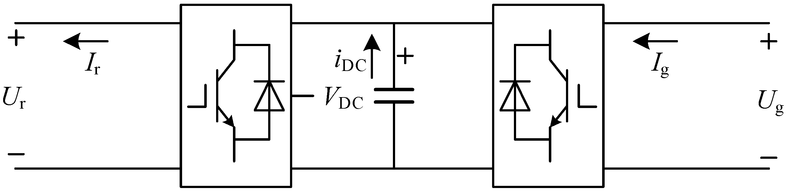
2.3. Model of the Back-to-Back Rotor Converters

As shown in Figure 3, the back-to-back rotor converter consists of a rotor-side converter, a grid-side converter, and a DC capacitor. The rotor-side converter excites the rotor with AC current, allowing the adjustment of rotor current frequency and phase, thereby regulating rotor speed and power factor. The grid-side converter primarily controls to achieve unity power factor and maintain the DC-link voltage, which ensures balance between the input and output power of the converter, while guaranteeing reliable operation of the rotor excitation system. The rotor-side converter, grid-side converter control system, and DC capacitor are modeled in detail.
The model of the converters can be written as
C d c V d c d V d c d t = P g P r
where C d c is the capacitance of the capacitor, V d c is the capacitor DC voltage, P g = u d g i d g + u q g i q g is the active power at the AC terminal of the grid-side converter, i d g and i q g are the d and q axis currents of the grid-side converter, respectively, u d g and u q g are the d and q axis voltages of the grid-side converter, P r = u d r i d r + u q r i q r is the active power at the AC terminal of the rotor-side converter, and i d r and i q r are the d and q axis currents of the rotor-side converter.

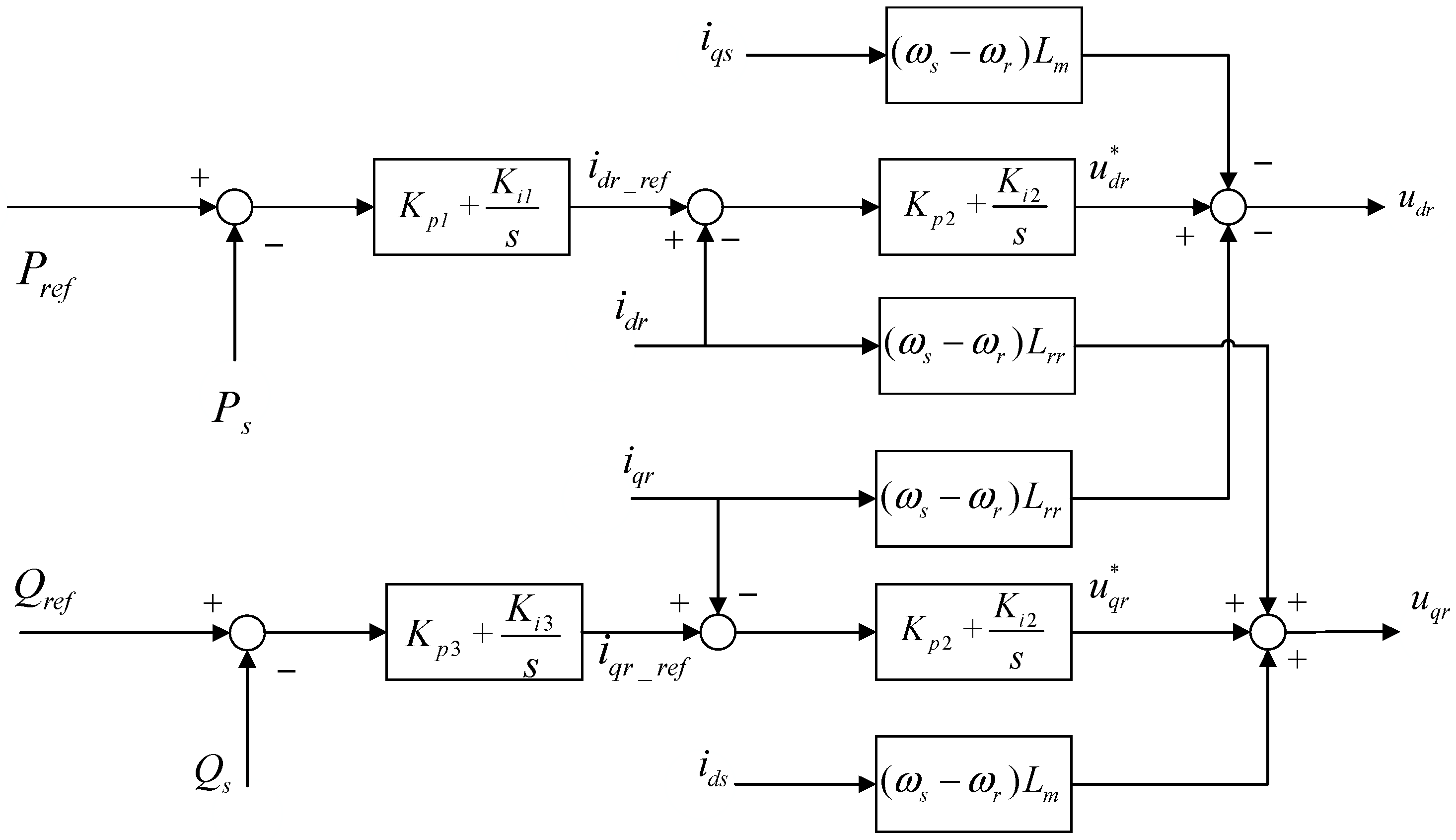
2.3.1. Rotor-Side Converter Controller Model

DFVSPS enables variable speed operation using AC excitation control. In generating mode, the turbine outputs mechanical torque to drive the DFIG. Due to the influence of inertia, the rate of change in electromagnetic power is much faster than that of mechanical power. Therefore, in generating mode, active power should be prioritized [39]. The rotor-side converter employs an outer-loop control strategy for active and reactive power and an inner-loop control for the rotor current, allowing for the rapid tracking of the active and reactive power reference values. The turbine governor controls the unit speed [40], with speed control being the priority in generating mode [41]. The control block diagram for the rotor-side converter in generating mode is shown in Figure 4.
Based on the control diagram, the controller can modeled as
d x 1 d t = P r e f P s d x 2 d t = = K p 1 x ˙ 1 + K i 1 x 1 i d r   d x 3 d t = Q r e f Q s d x 4 d t = K p 3 x ˙ 3 + K i 3 x 3 i q r
u d r = K p 2 x ˙ 2 + K i 2 x 2 s ω s L m i q s s ω s L r r i d r u q r = K p 2 x ˙ 4 + K i 2 x 4 + s ω s L m i d s + s ω s L r r i q r
where x 1 , x 2 , x 3 , x 4 are the intermediate variables, K p 1 and K i 1 are the proportional and integrating gains of the power regulator, respectively, K p 2 and K i 2 are the proportional and integrating gains of the rotor-side converter current regulator, respectively, K p 3 and K i 3 are the proportional and integrating gains of the grid voltage regulator, respectively, P r e f and Q r e f are the control reference of the active and reactive power of DFVSPS, and P s and Q s are the stator active and reactive power.

2.3.2. Grid-Side Converter Controller Model

The grid-side converter is connected between the grid and capacitor. It is controlled to stabilize the DC-link voltage at a reference value and output reactive power at the generator terminal. The regulation of the DC voltage and reactive power is controlled by the grid-side converter’s current components i d g and i q g , respectively. The control block diagram is shown in Figure 5.
With introducing the intermediate variables x 5 , x 6 and x 7 , the model of the grid-side converter can be obtained as follows:
d x 5 d t = V d c _ r e f V d c d x 6 d t = K p 4 x ˙ 5 + K i 4 x 5 i d g d x 7 d t = i q g _ r e f i q g
u d g = K p 5 x ˙ 6 + K i 5 x 6 + X T g i q g + u d s u q g = K p 5 x ˙ 7 + K i 5 x 7 X T g i d g + u q s
where K p 4 and K i 4 are the proportional and integrating gains of the DC bus voltage regulator, respectively, K p 5 and K i 5 are the proportional and integrating gains of the grid-side converter current regulator, V d c _ r e f is the voltage control reference of the DC link, and X T g is the reactance of the fed back transformer.

2.4. Model of Series Compensation Line

The actual series compensation degree in the power grid is determined by the equivalent inductance and capacitance of the entire system, and it can be modeled as
k = X C X L
where k is the series compensation degree, X C is the total capacitance of the entire system, X L is the total inductive reactance of the entire system, when only the compensation degree of the line needs to be calculated, and X L can be replaced by the inductive reactance value of the line. During small perturbation processes, the power grid may exhibit harmonic components, where the angular frequency ω n is related to the actual series compensation degree k .
ω n = k ω s
Neglecting the saturation effects of transformers T1 and T2 in Figure 1 and combining their equivalent reactances with the reactance of the transmission line, the equivalent model of the series-compensated line can be obtained as shown in Figure 6.
The dynamic equations of the series-compensated transmission line in the d − q reference frame are
L l d i d l d t = u d s R l i d l + ω s L l i q l u d c u d L l d i q l d t = u q s R l i q l ω s L l i d l u q c u q C l d u d c d t = i d l + ω s C l u q c C l d u q c d t = i q l ω s C l u d c
where L l is the equivalent reactance value obtained by combining the reactance of the transformer and the reactance of the line, C l is the capacitance of the series compensation line, R l is the resistance of the series compensation line, u d c and u q c are the d and q axis voltages of the series capacitor, u d and u q are the d and q axis voltages of the infinite bus, and i d l and i q l are the d and q axis currents of the series compensation line.

2.5. Dynamic Model of DFVSPS

Equations (1)–(16) describes the dynamic behavior of the grid-connected DFVSPS system. Linearizing the nonlinear differential equations of each part around the stable operating point and organizing them into matrix form, the small signal stability analysis model can be obtained:
d Δ X D d t = A D Δ X D + B D Δ Y D
where Δ X D and Δ Y D are the column vectors representing the state variables and algebraic variables of the entire system, respectively. The state variables consist of 21 orders, including a 5th-order water conveyance and pump-turbine model: X T P = [ Δ q 1 , Δ Z 1 , Δ q 2 , Δ μ , Δ ω r ] T ; a 4th-order doubly fed induction motor model: X g = [ Δ i d s , Δ i q s , Δ E d , Δ E q ] T ; a 4th-order rotor-side control model: X R S C = [ Δ x 1 , Δ x 2 , Δ x 3 , Δ x 4 ] T ; a 1st-order DC capacitor model: X d c = [ Δ V d c ] T ; a 3rd-order grid-side inverter control model: X G S C = [ Δ x 5 , Δ x 6 , Δ x 7 ] T ; and a 4th-order series compensation line model: X l i n e = [ Δ i d , Δ i q , Δ v c d , Δ v c q ] T . The algebraic variables consist of 10 orders and can be expressed as Δ Y D = [ Δ i d r , Δ i q r , Δ u d r , Δ u q r , Δ i d g , Δ i q g , Δ u d g , Δ u q g , Δ u d s , Δ u q s ] T .
Based on the topology of the DFVSPS system and the relationships between internal electrical quantities, the algebraic equations of the entire system can be linearized and organized into the following matrix form:
Δ Y D = C D Δ X D + D D Δ Y D
Solving Equations (17) and (18) simultaneously and eliminating the algebraic variable Δ Y D , the characteristic matrix equation for the entire system can be obtained as
d Δ X D d t = A SYS Δ X D
where A S Y S = A D + B D ( I D D ) 1 C D .

3. System Oscillation Characteristics Analysis

When a nonlinear system is subject to small disturbances, its stability can be analyzed through the linearized system to approximate the stability results. Based on Lyapunov’s stability criterion, the stability of a linear system can be determined by the eigenvalues of its state matrix. Therefore, the stability of the DFVSPS system can be assessed by calculating the eigenvalues of the characteristic matrix A S Y S . The criteria for judgment are as follows:
If the eigenvalue is a real number, it represents a non-oscillatory mode. When the real number is negative, it indicates a decaying mode, and the larger the absolute value, the faster the decay. Conversely, if the real number is positive, it indicates a non-periodic unstable mode, and the larger the absolute value, the faster the mode diverges.
If the eigenvalue is complex and exists in conjugate pairs, such as λ = σ ± j ω , it represents an oscillatory mode. The real part of the eigenvalue describes the damping of the oscillatory mode, while the imaginary part represents the frequency of the oscillatory mode. If the real part of the eigenvalue is negative, the mode tends to stabilize; otherwise, it will continue to oscillate with increasing amplitude. The frequency f and damping ratio ξ of the oscillation can be expressed as
f = ω 2 π ξ = σ σ 2 + ω 2
Calculating the eigenvalues of the characteristic matrix A, multiple oscillatory modes of the pumped storage system under small disturbances can be obtained. The system’s series compensation levels of 8%, 12%, and 20% were selected, and the eigenvalues were calculated, as listed in Table 1. The table lists four pairs of conjugate eigenvalues. The other real eigenvalues in the calculation results belong to non-oscillatory modes and are negative with large absolute values, indicating that these modes decay quickly and tend to stabilize; thus, they are not discussed further.
To verify the accuracy of the model, a corresponding model was also built in Power Systems Computer Aided Design (PSCAD) software (version 4.5), and the output power curves of the system were obtained for series compensation levels of 8%, 12%, and 20%. Fast Fourier Transform (FFT) was applied to analyze the frequency components of the active power within 1 to 2 s after the fault occurred, and the results are shown in Figure 7. In Figure 7, subplots a, c, and e show the output power of the DFVSPS system at series compensation levels of 8%, 12%, and 20%, respectively, while subplots b, d, and f present the FFT analysis results of the active power after a fault over a certain period at the corresponding compensation levels.
As shown in Figure 7, when the system’s series compensation level is 8%, no oscillation occurs in the output power, which is consistent with the theoretical analysis result that all eigenvalues of the state-space matrix lie in the left half-plane. When the series compensation is 12%, the oscillation in the output power of the DFVSPS unit begins around the 11th second in the simulation model, with a Fourier analysis showing an oscillation frequency of 55.04 Hz. The corresponding real part of the eigenvalue is 0.02, the theoretical oscillation frequency calculated from the eigenvalue is 54.25 Hz, and they are close to each other. At a 20% compensation level, the oscillation in the power output of the variable speed unit begins around 10.1 s, with a Fourier analysis yielding an oscillation frequency of 53.05 Hz. The real part of the corresponding eigenvalue is 1.11, and the theoretical oscillation frequency is calculated to be 52.54 Hz. Additionally, the real part of the eigenvalue for this oscillation mode is larger than that of the 12% compensation mode, which aligns with the earlier onset of oscillation. Thus, the state-space model established in this paper is accurate for the oscillation analysis. The result demonstrates that as the series compensation level increases, the system becomes more prone to SSO, with a lower oscillation frequency.
Calculating the frequencies and damping of each mode as listed in Table 1, it is found that under different series compensation levels, the frequency of mode λ is always greater than the synchronous frequency, while the frequency of mode λ 3 , 4 is always less than the synchronous frequency, with both frequencies being approximately symmetrical around the synchronous frequency. Taking a series compensation level of 8% as an example, and as shown by Equation (15), the DFVSPS power system must have a resonant component with a frequency of approximately 5.88 Hz under small disturbances. Given the power frequency of 60 Hz, the frequency of the super-synchronous oscillation mode in the system should be 65.88 Hz, and the sub-synchronous oscillation mode should be 54.12 Hz. The frequencies of modes λ 1 , 2 and λ 3 , 4 are 64.34 Hz and 55.32 Hz, respectively, both of which are close to the theoretical frequencies. Therefore, mode λ 1 , 2 corresponds to the super-synchronous mode, and mode λ 3 , 4 corresponds to the sub-synchronous mode. The eigenvalue of mode λ 7 , 8 is essentially unaffected by changes in the series compensation level.
To investigate the impact of each state variable on different oscillation modes further, a relative participation analysis is conducted using the eigenvalues of the state-space matrix when the system is operating at an 8% series compensation level. Using the left eigenvector and the right eigenvector, the relative participation of the i th variable in the j th mode can be measured by the participation factor, which is given by p i j = ϕ i j φ i j . The results of the relative participation analysis are illustrated in Figure 8. Figure 8a, b, c and d show the relative participation analysis for modes 12, 34, 56, and 78, respectively.
In Figure 8, state variables 1 to 4 represent the variables of the series compensator ( Δ i d l , Δ i q l , Δ u d c , Δ u q c ); state variables 5 to 8 represent the variables of the DFIG ( Δ i d s , Δ i q s , Δ E d , Δ E q ); state variables 9 to 11 represent the variables of the water conveyance system ( Δ q 1 , Δ Z 1 , Δ q 2 ); state variables 12 to 13 represent the variables of the pump turbine ( Δ μ , Δ ω r ); state variables 14 to 17 represent the rotor-side variables ( Δ x 1 , Δ x 2 , Δ x 3 , Δ x 4 ); state variable 18 represents the state variable of the DC capacitor ( Δ V d c ); and state variables 19 to 21 represent the stator-side variables ( Δ x 5 , Δ x 6 , Δ x 7 ).
As shown in Figure 8, modes λ 1 , 2 , λ 3 , 4 , and λ 5 , 6 are strongly correlated with the state variables of the series-compensated line, the induction generator, and the rotor-side controller, while state variables Δ E d and Δ E q are related to the rotor flux linkage and are influenced by the rotor-side excitation controller. Therefore, these three oscillation modes are categorized as electrical oscillations, indicating that the dynamic characteristics of the series-compensated line, the doubly fed induction generator, and the rotor-side controller significantly affect both sub-synchronous and super-synchronous oscillation modes. Mode λ 7 , 8 is strongly correlated with the water conveyance system variables and turbine variables, with almost no correlation to electrical variables. This is because the system operates in generating mode, where the rotor-side control prioritizes active power control, leading to mechanical–electrical decoupling. If the system were in pumping mode, where rotor control prioritizes power control, there would inevitably be oscillation modes involving mechanical–electrical coupling.
From this analysis, it can be concluded that in a DFVSPS system with a water conveyance system and series-compensated line, there are both hydraulic–mechanical coupling and electrical oscillation modes. However, there are no oscillation modes strongly correlated with hydraulic–mechanical–electrical state variables simultaneously, and the oscillation modes are highly influenced by the system controller parameters. In conclusion, when the DFVSPS system operates in generating mode, there is a physical decoupling between the hydraulic–mechanical and electrical components, meaning they generally do not affect each other. However, improper parameters in the hydraulic–mechanical component may induce low-frequency mechanical oscillations, potentially leading to accidents and compromising the overall system’s safety and stability. Therefore, when developing a DFVSPS system model, it is essential to include the water conveyance system model and suppress its low-frequency oscillations. At the same time, appropriate methods must also be applied to suppress SSOs in the electrical component.

4. Analysis of the Suppression Effect of Controller Parameters on DFVSPS System Oscillations

Based on the content in Section 3, this section continues to analyze the effect of initial controller parameters on the system’s stability when encountering small disturbances. The goal is to identify an appropriate stability range for the initial parameters, ensuring that when the controller parameters are fixed, any sub-synchronous or low-frequency oscillations generated during system faults can converge without jeopardizing the safe operation of the system.

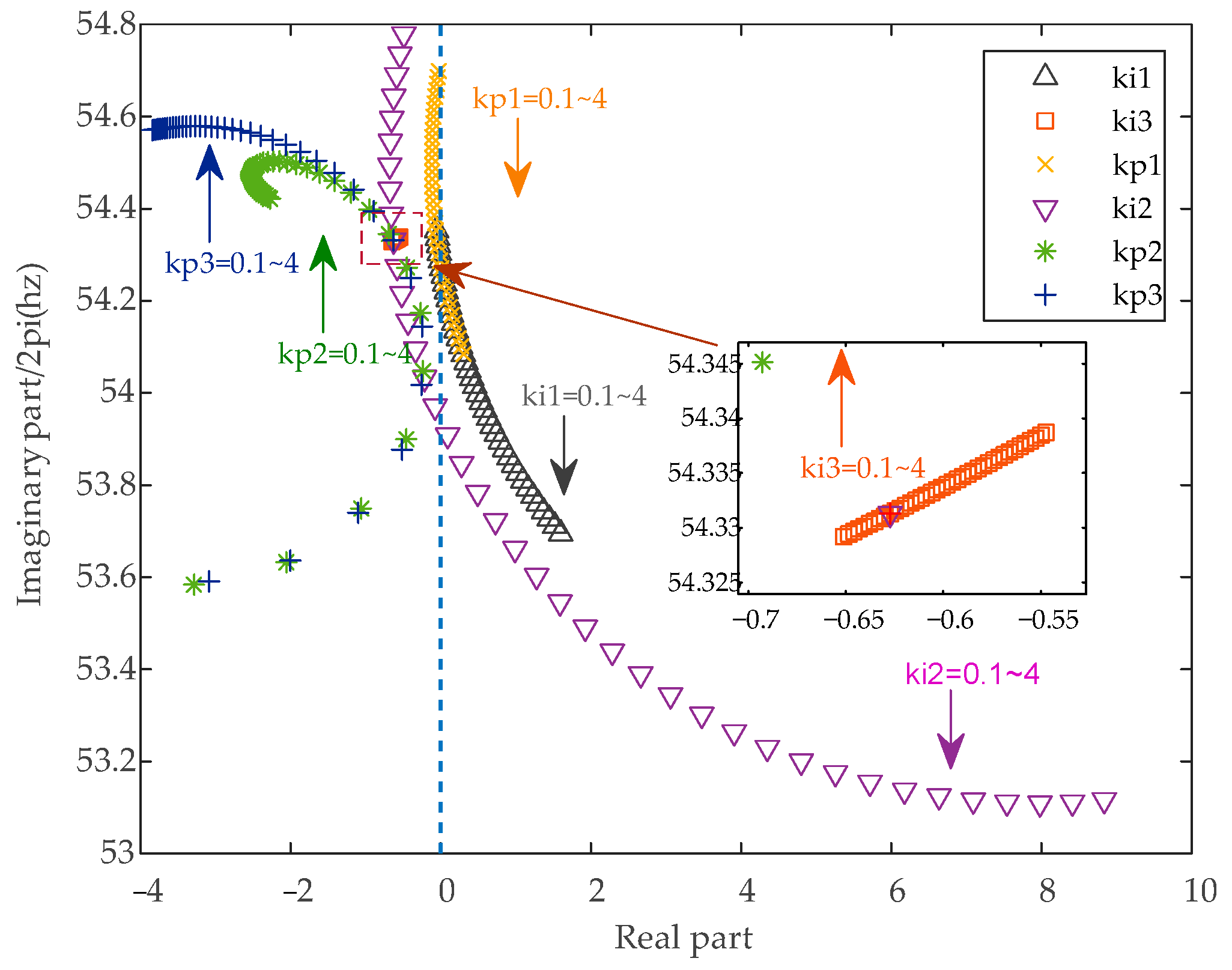
4.1. Analysis of the Suppression Effect of SSOs by Rotor-Side PI Controller Parameters

According to the relative participation analysis, it is clear that oscillation modes λ 1 , 2 , λ 3 , 4 and λ 5 , 6 are closely related to the electrical state variables. Therefore, selecting appropriate rotor-side PI controller parameters may help to more effectively suppress system oscillations. In Equations (10) and (11), there are four PI controllers in the rotor-side control loop, which include a total of six controller parameters. When analyzing the effect of each parameter on the SSO modes, we adjust only the value of the specific controller parameter while keeping the others unchanged. Using the eigenvalue analysis method, the effect of increasing each rotor-side controller parameter from 0.1 to 4 on system oscillations at a series compensation level of 12% was calculated. The results are shown in Figure 9.
In Figure 9, the blue dashed line represents the boundary between the stable and unstable regions. The arrows perpendicular to the horizontal plane indicate the direction in which the eigenvalue points move as the controller parameter increases. For example, if the arrow corresponding to K p 1 points downward, it means that as K p 1 increases, the SSO frequency of the system gradually decreases. When the eigenvalue corresponding to the controller parameter is on the left side of the blue dashed line, the system’s oscillations will converge if it encounters a small disturbance, and the system will tend to stabilize. Conversely, when the eigenvalue is on the right side of the blue dashed line, the oscillations will diverge if the system encounters a small disturbance, and the system will become unstable.
The results indicate that in the constructed DFVSPS system, increasing the values of K p 2 , K p 3 , and K i 3 to a certain extent will lead to an increase in the SSO frequency, while keeping the system stable. However, as the values of K p 1 , K i 1 , and K i 2 increase, the sub-synchronous mode moves further into the right half-plane each time, and the corresponding frequency of the mode significantly decreases. This suggests that increasing the proportional gain of the PI controllers not only reduces the stability of the sub-synchronous mode but also lowers the frequency of SSOs. It is noteworthy that when these three parameters have relatively small values, the sub-synchronous mode can be positioned on the left side of the blue dashed line. This indicates that appropriately adjusting the values of the PI controller parameters can help the DFVSPS system avoid SSOs. In practical applications, if the proportional gain of the PI controller is too large, the system may experience oscillations and instability; if it is too small, the response becomes sluggish, with larger errors. Similarly, if the integral gain is too large, it can lead to overshoot and instability, while a smaller gain increases steady-state error and slows the response. Therefore, it is essential to first determine the stable range of controller parameters and then build a simulation model based on the actual situation, gradually adjusting the proportional and integral gains until a balance is achieved between response speed, stability, and accuracy.

4.2. Analysis of the Suppression Effect of Low-Frequency Oscillations by Hydraulic–Mechanical System Parameters

Through the relative participation analysis of oscillation modes, it is found that in the DFVSPS system with a water conveyance system operating under generating conditions, there are no oscillation modes that are strongly correlated with both the hydraulic and electrical components simultaneously. Moreover, low-frequency oscillation modes are only related to the hydraulic–mechanical parameters. Therefore, for the analysis of low-frequency oscillations arising from the selection of parameters in the intake system, it is sufficient to consider only the hydraulic–mechanical part of the model for ease of computation.
Five different cases are adopted to analyze the system. The method of traversal is employed to calculate the real parts of the eigenvalues of the system matrix for different combinations of surge tank area and governor parameters in Equations (4) and (6). By determining whether the real parts of the eigenvalues lie in the left half-plane, the stability region of the system can be obtained. The analysis results are shown in Figure 10.
Case   1 :   F u = 80 ,   b t = 0.4 ,   T d = 5 ;
Case   2 :   F u = 100 ,   b t = 0.4 ,   T d = 6 ;
Case   3 :   F u = 120 ,   b t = 0.4 ,   T d = 6 ;
Case   4 :   F u = 120 ,   b t = 0.6 ,   T d = 6 ;
Case   5 :   F u = 120 ,   b t = 0.6 ,   T d = 10 ;
As shown in Figure 10, different colored asterisks represent the different positions of points in the figure, with the corresponding b t values as the x-coordinates and T d values as the y-coordinates. Each case with different surge tank areas has only one boundary line for the stable region. For the selected surge tank parameters, the system remains stable if the parameters are above the boundary line. The parameters from case 1 fall below the stability line, placing it in the instability region, which results in divergence under small disturbances. The other four cases are within the stable region, indicating that the system will converge under small disturbances. Furthermore, as the surge tank area increases, the stability region of the system enlarges, providing more flexibility in parameter selection. Further analysis shows that as the surge tank area increases, the decay rate of oscillations under small disturbances increases, and the corresponding oscillation angular frequency decreases. Therefore, cases 3, 4, and 5 are evidently better than case 2. The relationship between surge tank area (increasing in intervals of 20 m 2 ), decay rate, and oscillation angular frequency is illustrated in Figure 11.
In practical engineering, the surge tank area is limited by various conditions and should not be excessively large. In such cases, it is necessary to adjust the governor parameters to better ensure system stability. Using the ode45 algorithm continued to solve the state-space characteristic equations for the system under the parameters of cases 3, 4, and 5. We selected a scenario where the relative flow in the long water conveyance tunnel increased suddenly by 10%. The dynamic response of the unit speed and the surge tank water level fluctuations for each case were obtained, as shown in Figure 12.
Figure 12 indicates that under case 3, case 4, and case 5, the system converges when subjected to small disturbances. However, the convergence speeds vary; case 5 exhibits the fastest convergence, while case 3 shows the slowest. Therefore, within a certain range, increasing the parameters of the speed governor can enhance system stability, accelerate the convergence of oscillations during small disturbances, and improve the safety of the hydro-mechanical part. Additionally, the mechanical oscillations of the DFVSPS have extremely low frequencies, with oscillation periods measured in hundreds of seconds, and very small amplitudes. For electrical oscillations with time scales in milliseconds, the oscillation of turbine speed converges almost imperceptibly, appearing as a stable straight line. This further validates that electrical oscillations are minimally influenced by the hydraulic–mechanical state variables. Similar to the electrical components, the hydraulic part also requires building a simulation model in practical applications. Parameters need to be gradually adjusted within the correct stability range until a balance is achieved between response speed, stability, and accuracy.

5. Discussion

Compared to previous research on DFVSPSP modeling and simulation, the main contributions and innovations of this paper are as follows:
(1)
Complete theoretical model: This paper establishes a complete DFVSPS system model, considering the water conveyance system to the transmission lines, and develops modular, detailed subsystem models. This approach facilitates the study of the hydro-mechanical–electrical coupling relationships and the impact of each subsystem on the overall model.
(2)
Effect of series compensation on oscillations: Based on the similarity in structure between DFVSPS and DFIG, a scenario was built where the DFVSPS system is connected to the grid through series compensation. The impact of different levels of series compensation on the system’s oscillatory characteristics was then analyzed.
(3)
Relative participation analysis: Based on the constructed state-space model, this paper analyzes the influence of various state variables on the system’s oscillatory modes. This helps identify key state variables and allows for their adjustment to enhance system stability.
(4)
Effect of controller parameters on oscillations: Using the model established in this paper, the impact and suppression effects of different controller parameters on SSOs in the electrical part and low-frequency oscillations in the hydro-mechanical part were analyzed. The stable range of control parameters was determined, and guidance on how to adjust controller parameters based on real-world conditions was provided.
At the same time, this study has certain limitations, and there are some issues that can be further explored in future research.
(1)
The limitation of the small-signal model established in this paper lies in its assumption that the input signals to the system are sufficiently small, allowing the linearization approximation to hold. This restricts its applicability in cases involving nonlinear or large-amplitude signals.
(2)
This paper only considers the DFVSPS system operating in generation mode. Whether the system can utilize its characteristics to enhance power system stability when operating in pumping mode remains a question for future research.
(3)
This paper analyzes the suppression effect of controller parameters on the system’s small disturbance stability, focusing on selecting appropriate fixed initial parameters to ensure system stability. In the future, it may be beneficial to consider incorporating optimization methods such as artificial intelligence and deep learning for the real-time tracking and adjustment of the system’s controller parameters to achieve better control outcomes.
(4)
In the future, the focus of research on SSOs in the DFVSPS system should be on the electrical oscillations induced by the converter control system; the hydraulic system parameters are the key focus for studying low-frequency oscillations in the system. Efforts should focus on optimizing controller parameters, adding damping controllers, and other methods to better suppress oscillations in the DFVSPS system. For example, artificial intelligence or machine learning can adaptively adjust control parameters by analyzing system data and operating conditions in real time, ensuring optimal performance under various operating scenarios. With these technologies, control systems can respond more flexibly to complex working conditions.

6. Conclusions

This paper investigates the sub-synchronous and low-frequency oscillation characteristics of a DFVSPS system connected to the grid through series compensation lines using a state-space model and time-domain simulations. A detailed model of the DFVSPS system is built. Based on this model, a small-disturbance linear system model for the system under generation conditions with series compensation was derived. The dominant sub-synchronous and low-frequency oscillation modes were identified. The effects of series compensation, back-to-back converter control parameters, and real waterway parameters on these modes were analyzed, and the model’s accuracy was validated through simulations. The main conclusions of this study are as follows:
(1)
The SSO modes induced by the integration of a DFVSPS system with a series-compensated transmission line are significantly correlated with the dynamics of the line capacitance, inductance, the induction generator, and the rotor-side control system. In contrast, the low-frequency mechanical oscillation modes are solely related to the hydraulic–mechanical components.
(2)
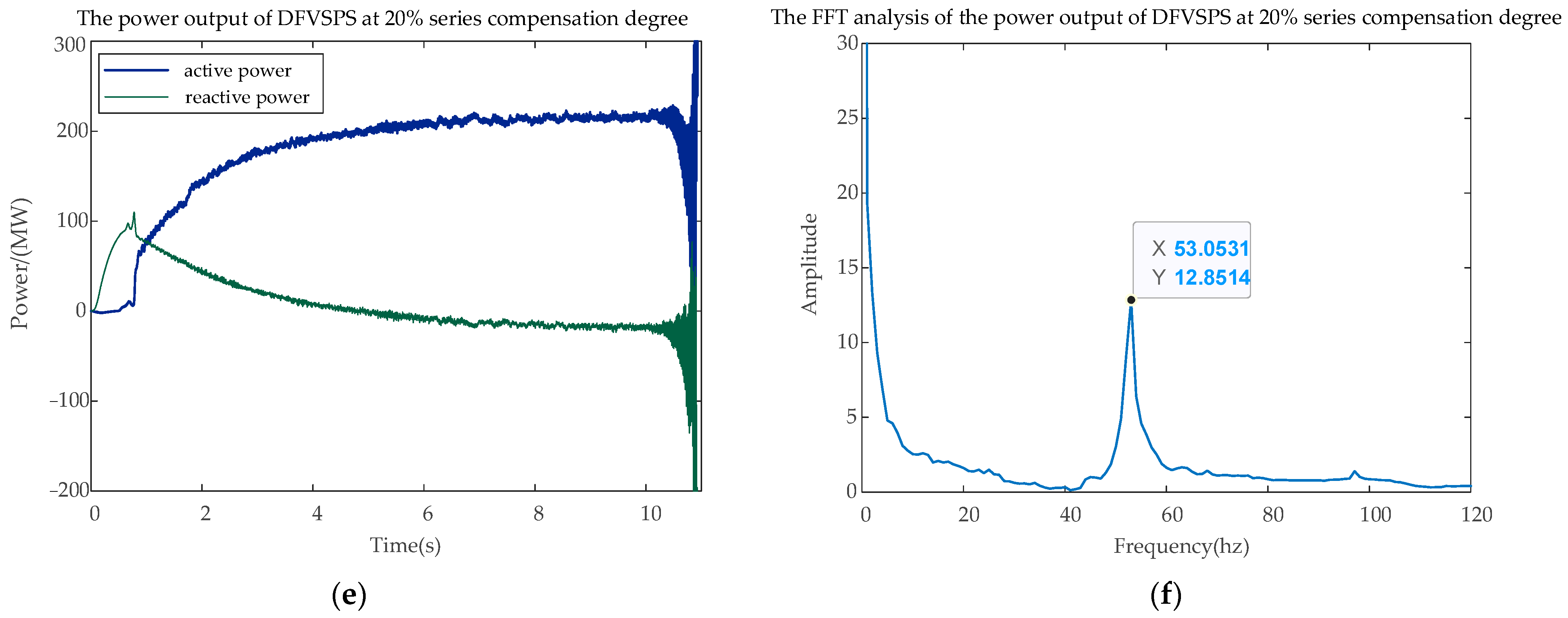
Under the same control parameters, an increase in the series compensation degree of the transmission line will induce stronger SSOs in the DFVSPS system. Higher compensation levels lead to more intense oscillations. Additionally, the SSO frequency is primarily determined by the actual series compensation degree of the grid. As the compensation degree increases, the natural resonant frequency of the grid under small disturbances increases, resulting in a gradual decrease in the frequency of SSOs.
(3)
The SSO modes in the DFVSPS system caused by series-compensated transmission lines are strongly related to electrical parameters and are independent of hydraulic–mechanical parameters. Selecting appropriate rotor-side controller parameters can effectively suppress the system’s SSOs, making them converge and shifting the eigenvalues from the right half-plane to the left half-plane.
(4)
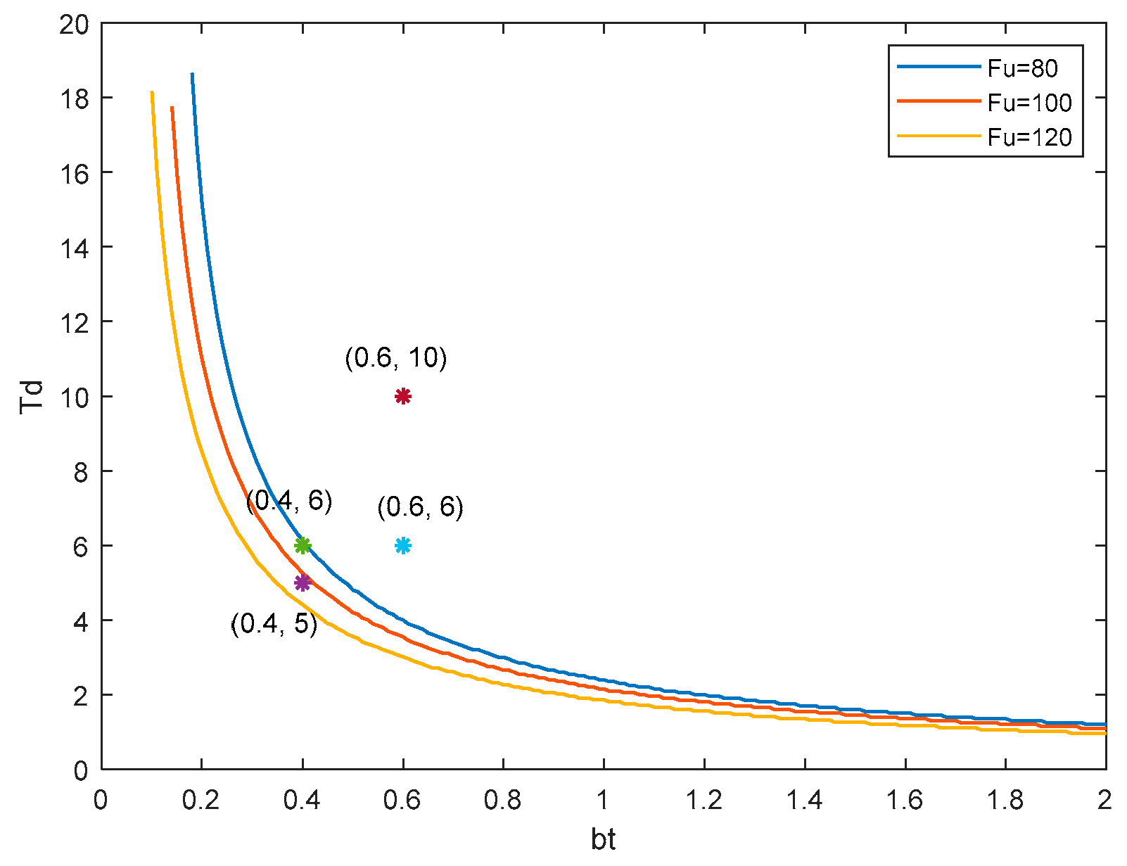
When the DFVSPS unit with a water conveyance system operates under generation conditions, it exhibits both hydraulic–mechanical coupling and electromechanical decoupling. Therefore, the hydraulic system and the electromechanical system can be analyzed separately. In the hydraulic system, increasing the surge tank area can enhance the stability of the system’s low-frequency oscillation components and expand the stable region for the selection of governor parameters. Increasing the governor parameters allows the system to converge more quickly and become more stable under small disturbances.

Author Contributions

Conceptualization, Y.C.; methodology, Y.C.; software, Y.C.; validation, Y.C.; formal analysis, X.G. and P.Q.; investigation, Y.C.; resources, L.S. and Y.L.; data curation, Y.C.; writing—original draft preparation, Y.C.; writing—review and editing, F.W. and L.S.; visualization, X.G. and P.Q.; supervision, L.S. and Y.L.; project administration, F.W.; funding acquisition, F.W. All authors have read and agreed to the published version of the manuscript.

Funding

This research was funded by NSFC, U23B20140.

Data Availability Statement

The data presented in this study are available upon request from the corresponding author.

Conflicts of Interest

The authors declare no conflicts of interest.

Appendix A

Parameters of Water Conveyance and Pump-Turbine System
T w 1 = 0.69 s      T w 2 = 0.25 s
α 1 = 6.41 × 10 5 s 2 / m 5      α 2 = 5.23 × 10 4 s 2 / m 5
H 0 = 481 m      Q 0 = 84.9 m 3 / s
F u = 100 m 2      T a = 9 s
T d = = 8 s
s 5 = 1.2425    s 6 = 0 . 7575    s 7 = 1 . 0609
s 8 = 2 . 6543    s 9 = 0 . 3457    s 10 = 1 . 2729
S p = 0 b t = 0 . 6 b p
Parameters of DFIG
Rated Power: 313 MW Rated Voltage: 10.5 kV
R s = 0 . 00540 p u R r = 0 . 00607 p u
L m = 2 . 3621 p u    L r = 0 . 11 p u
L s = 0 . 102 p u ω s = 376 . 98 r a d / s
C d c = 2 F    V d c 0 = 0.8 kV
X T g = 0.05 ( p u )
Parameters of Controller
K p 1 = 3    K i 1 = 1 / 0.3
K p 2 = 3    K i 2 = 1 / 0.1
K p 3 = 0.8    K i 3 = 1 / 0.1
K p 4 = 10    K i 4 = 1 / 0.01
K p 5 = 10    K i 5 = 1 / 0.01
Parameters of Lines in Figure 1
R 1 = 6.471 o h m      R 2 = 0.001 o h m
L 1 = 0.1014 ( H )      L 1 = 0.1 ( H )
L T 1 = 0.1 p u      L T 2 = 0.1 p u
C = 115.6 u F

References

  1. Cheng, Y.Z.; Fan, L.L.; Rose, J.; Huang, S.H.; Schmall, J.; Wang, X.Y.; Xie, X.R.; Shair, J.; Ramamurthy, J.R.; Modi, N.; et al. Real-World Subsynchronous Oscillation Events in Power Grids with High Penetrations of Inverter-Based Resources. IEEE Trans. Power Syst. 2023, 38, 316–330. [Google Scholar] [CrossRef]
  2. Liu, G.; Liu, J.; Liu, A.D. Mitigating sub-synchronous oscillation using intelligent damping control of DFIG based on improved TD3 algorithm with knowledge fusion. Sci. Rep. 2024, 14, 14692. [Google Scholar] [CrossRef]
  3. Li, Y.; Wu, F.; Li, J.Y.; Yin, Y.W.; Li, Z.Y.; Ai, L. Chance-constrained energy management for pumped storage hydropower plant to compensate for wind power uncertainties. In Proceedings of the 2021 IEEE Power & Energy Society General Meeting (PESGM), Washington, DC, USA, 20 December 2021. [Google Scholar]
  4. Khurshid, H.; Mohammed, B.S.; Al-Yacouby, A.M.; Liew, M.S.; Zawawi, N. Analysis of hybrid offshore renewable energy sources for power generation: A literature review of hybrid solar, wind, and waves energy systems. Dev. Built Environ. 2024, 19, 100497. [Google Scholar] [CrossRef]
  5. Cui, R.; Guo, J.; Cheng, L.; Zhang, Y.; Liu, W. Status and Trends Analysis of Global Clean Energies. Acta Geosci. Sin. 2021, 42, 179–186. [Google Scholar]
  6. Ma, X.; Wu, D.; Wang, D.X.; Huang, B.W.; Desomber, K.; Fu, T.; Weimar, M. Optimizing pumped storage hydropower for multiple grid services. J. Energy Storage 2022, 51, 104440. [Google Scholar] [CrossRef]
  7. Huang, W.; Li, Y.; Li, J.; Liu, Y.; Wu, F.; Wang, Z. Multi-time scale joint optimal scheduling for wind-photovoltaic-electrochemical energy storage-pumped storage considering renewable energy uncertainty. Electr. Power Autom. Equip. 2023, 43, 91–98. [Google Scholar]
  8. Papakonstantinou, A.G.; Konstanteas, A.I.; Papathanassiou, S.A. Solutions to Enhance Frequency Regulation in an Island System with Pumped-Hydro Storage under 100% Renewable Energy Penetration. IEEE Access 2023, 11, 76675–76690. [Google Scholar] [CrossRef]
  9. Han, M.X.; Bitew, G.T.; Mekonnen, S.A.; Yan, W.L. Wind Power Fluctuation Compensation by Variable Speed Pumped Storage Plants in Grid Integrated System: Frequency Spectrum Analysis. CSEE J. Power Energy Syst. 2021, 7, 381–395. [Google Scholar]
  10. Wang, Z.; Wang, W.; Ma, W.; Chen, Z.; Wu, X.; Tang, F. Real-time Coordinated Control for Cascade Hydro-photovoltaic-pumped Storage Complementary Generation System. Power Syst. Technol. 2021, 45, 871–881. [Google Scholar]
  11. Xu, B.; Zhu, F.; Zhong, P.A.; Chen, J.; Liu, W.F.; Ma, Y.F.; Guo, L.; Deng, X.L. Identifying long-term effects of using hydropower to complement wind power uncertainty through stochastic programming. Appl. Energy 2019, 253, 113535. [Google Scholar] [CrossRef]
  12. Zhang, H.; Chen, M.; Peng, Y.M.; Zhou, J.W.; He, R.F. Technology Summary on the Application of Variable-Speed Pump-Turbine Units for Wind Storage Operation. In Proceedings of the 2019 IEEE 3rd International Electrical and Energy Conference (CIEEC), Beijing, China, 7–9 September 2019; pp. 232–235. [Google Scholar]
  13. Yao, W.W.; Li, W.; Liu, R.K.; Sun, Y. Optimal capacity of variable-speed pumped storage for wind power consumption based on double-layer stochastic programming. J. Renew. Sustain. Energy 2023, 15, 024103. [Google Scholar] [CrossRef]
  14. Kumar, R.; Kumar, A. Optimal scheduling of variable speed pumped storage, solar and wind energy system. Energy Sources Part A-Recovery Util. Environ. Eff. 2021, 2021, 1–16. [Google Scholar] [CrossRef]
  15. Deng, Y.W.; Wang, P.F.; Morabito, A.; Feng, W.F.; Mahmud, A.; Chen, D.Y.; Hendrick, P. Dynamic analysis of variable-speed pumped storage plants for mitigating effects of excess wind power generation. Int. J. Electr. Power Energy Syst. 2022, 135, 107453. [Google Scholar] [CrossRef]
  16. Li, C.S.; Tan, X.Q.; Lu, X.D.; Zhu, Z.W.; Xu, R.L.; Liu, X.B.; Wang, Z.W. Multi-timescale analysis and quantification of dynamic regulation characteristics of DFIM-based variable-speed pumped storage units in alleviating wind power fluctuations. J. Energy Storage 2024, 88, 111482. [Google Scholar]
  17. Iliev, I.; Trivedi, C.; Dahlhaug, O.G. Variable-speed operation of Francis turbines: A review of the perspectives and challenges. Renew. Sustain. Energy Rev. 2019, 103, 109–121. [Google Scholar] [CrossRef]
  18. Jing, H.; Li, J.; Zhao, H.; Xu, Q.; Yao, W.; Wang, B. Modeling and Simulation of Operating Condition Conversion of Doubly-Fed Variable Speed Pumped Storage. Electr. Power Constr. 2023, 44, 41–50. [Google Scholar]
  19. Pan, P.Y.; Chen, G.; Shi, H.B.; Zha, X.M.; Huang, Z.Q. Distributed Robust Optimization Method for Active Distribution Network with Variable-Speed Pumped Storage. Electronics 2024, 13, 3317. [Google Scholar] [CrossRef]
  20. Liu, K.; Zhu, S.; Feng, X.; Deng, C.; Chen, M.; Li, D. Electromechanical Transient Modeling and Model Predictive Control of Doubly-fed Variable- speed Pumped Storage Power Plant. High Volt. Eng. 2020, 46, 2407–2417. [Google Scholar]
  21. Zhao, G.P.; Ren, J.Y. Research on an Output Power Model of a Doubly-Fed Variable-Speed Pumped Storage Unit with Switching Process. Appl. Sci. 2019, 9, 3368. [Google Scholar] [CrossRef]
  22. Hu, J.M.; Tao, D.J.; Sun, Y.T.; Zhang, C.L.; Li, G.F.; Hu, G. Analysis of Operating Characteristics of Variable Speed Pumped Storage Motor-Generator. IEEE Access 2023, 11, 52117–52128. [Google Scholar]
  23. Chen, Y.H.; Xu, W.; Liu, Y.; Bao, Z.; Mao, Z.X.; Rashad, E.M. Modeling and Transient Response Analysis of Doubly-Fed Variable Speed Pumped Storage Unit in Pumping Mode. IEEE Trans. Ind. Electron. 2023, 70, 9935–9947. [Google Scholar] [CrossRef]
  24. Chen, Y.; Deng, C.; Liu, Y.; Xu, Z.; Li, D.; Chen, M.; Peng, P. Electromechanical Transient Modelling and Active Power-frequency Coupling Characteristics of Doubly-fed Variable Speed Pumped Storage under Pumping Mode. Proc. Chin. Soc. Electr. Eng. 2022, 42, 942–956. [Google Scholar]
  25. Wang, X.; Han, M.; Girmaw, T.B. Reactive Power Characteristic Analysis of Doubly-fed Adjustable-speed Pumped Storage Unit. Power Syst. Technol. 2019, 43, 2918–2925. [Google Scholar]
  26. Li, G.H.; Zhang, J.; Wu, X.M.; Yu, X.D. Small-Signal Stability and Dynamic Behaviors of a Hydropower Plant with an Upstream Surge Tank Using Different PID Parameters. IEEE Access 2021, 9, 104837–104845. [Google Scholar] [CrossRef]
  27. Liu, Y.; Yu, X.D.; Guo, X.L.; Zhao, W.L.; Chen, S. Operational Stability of Hydropower Plant with Upstream and Downstream Surge Chambers during Small Load Disturbance. Energies 2023, 16, 4517. [Google Scholar] [CrossRef]
  28. Xu, B.B.; Zhang, J.J.; Egusquiza, M.; Chen, D.Y.; Li, F.; Behrens, P.; Egusquiza, E. A review of dynamic models and stability analysis for a hydro-turbine governing system. Renew. Sustain. Energy Rev. 2021, 144, 110880. [Google Scholar] [CrossRef]
  29. Wang, F.Z.; Zhu, S.; Liu, K.P.; Chen, M.; Du, Y.X. Impedance modeling of wind turbine-variable speed pumped storage combined operation system. Energy Rep. 2021, 7, 470–478. [Google Scholar] [CrossRef]
  30. YHuang, F.; Yang, W.J.; Zhao, Z.G.; Han, W.F.; Li, Y.L.; Yang, J.D. Dynamic modeling and favorable speed command of variable-speed pumped-storage unit during power regulation. Renew. Energy 2023, 206, 769–783. [Google Scholar]
  31. Wang, F.; Tan, T.; Liu, K.; Zhu, S.; Yang, J.; Li, Y.; Hu, C.; Qin, L. Small-signal stability analysis of combined operation system of variable-speed pumped storage unit and direct-drive wind turbine unit. Electr. Power Autom. Equip. 2021, 41, 65–72. [Google Scholar]
  32. Wu, Y.F.; Liu, J.F.; Zhou, J. The Strategy of Considering the Participation of Doubly-Fed Pumped-Storage Units in Power Grid Frequency Regulation. Energies 2022, 15, 2179. [Google Scholar] [CrossRef]
  33. Gao, C.Y.; Yu, X.Y.; Nan, H.P.; Men, C.S.; Zhao, P.Y.; Cai, Q.S.; Fu, J.N. Stability and dynamic analysis of doubly-fed variable speed pump turbine governing system based on Hopf bifurcation theory. Renew. Energy 2021, 175, 568–579. [Google Scholar] [CrossRef]
  34. Zhang, N.; Xue, X.M.; Sun, N.; Gu, Y.H.; Jiang, W.; Li, C.S. Nonlinear Modeling and Stability of a Doubly-Fed Variable Speed Pumped Storage Power Station with Surge Tank Considering Nonlinear Pump Turbine Characteristics. Energies 2022, 15, 4131. [Google Scholar] [CrossRef]
  35. Fan, L.L.; Kavasseri, R.; Miao, Z.L.; Zhu, C.X. Modeling of DFIG-Based Wind Farms for SSR Analysis. IEEE Trans. Power Deliv. 2010, 25, 2073–2082. [Google Scholar] [CrossRef]
  36. Liang, J.Q.; Harley, R.G. Pumped Storage Hydro-Plant Models for System Transient and Long-Term Dynamic Studies. In Proceedings of the IEEE Power and Energy Society General Meeting PESGM, Minneapolis, MN, USA, 25–29 July 2010. [Google Scholar]
  37. Yu, X.D.; Yang, X.W.; Liu, Z.; Zhang, J. Mechanism and quantified criteria of stability characteristics of hydropower plants with surge tanks during regulation. Int. J. Electr. Power Energy Syst. 2020, 122, 106160. [Google Scholar] [CrossRef]
  38. Liu, Z.; Yu, X.D.; Pérez-Díaz, J.I.; Liu, Y.; Martínez-Lucas, G. Influence of water hammer effect on low frequency oscillation of grid-connected hydropower station system. Renew. Energy 2023, 219, 119530. [Google Scholar] [CrossRef]
  39. Zhao, G.P.; Zhang, Y.X.; Ren, J.Y. Analysis of Control Characteristics and Design of Control System Based on Internal Parameters in Doubly Fed Variable-Speed Pumped Storage Unit. Complexity 2021, 2021, 6697311. [Google Scholar] [CrossRef]
  40. Shi, L.J.; Lao, W.J.; Wu, F.; Lee, K.Y.; Li, Y.; Lin, K.M. DDPG-based load frequency control for power systems with renewable energy by DFIM pumped storage hydro unit. Renew. Energy 2023, 218, 119274. [Google Scholar] [CrossRef]
  41. Shi, L.J.; Lao, W.J.; Wu, F.; Zheng, T.; Lee, K.Y. Frequency Regulation Control and Parameter Optimization of Doubly-Fed Induction Machine Pumped Storage Hydro Unit. IEEE Access 2022, 10, 102586–102598. [Google Scholar] [CrossRef]
Figure 1. Structure of the complete DFVSPS system connected to the power grid.
Sustainability 16 08715 g001
Figure 2. Structure of the water conveyance power generation system diagram.
Sustainability 16 08715 g002
Figure 3. Steady equivalent circuit of the back-to-back rotor converters.
Sustainability 16 08715 g003
Figure 4. Rotor-side converter control block diagram with DFIG system.
Sustainability 16 08715 g004
Figure 5. Grid-side converter control block diagram with DFIG system.
Sustainability 16 08715 g005
Figure 6. Diagram of the series compensation line equivalent model.
Sustainability 16 08715 g006
Figure 7. The power output and FFT analysis results of PSCAD simulation under different series compensation degrees. (a) The power output of DFVSPS at 8% series compensation degree; (b) FFT analysis of the power output of DFVSPS at 8% series compensation degree; (c) the power output of DFVSPS at 12% series compensation degree; (d) FFT analysis of the power output of DFVSPS at 12% series compensation degree; (e) the power output of DFVSPS at 20% series compensation degree; (f) FFT analysis of the power output of DFVSPS at 20% series compensation degree.
Sustainability 16 08715 g007aSustainability 16 08715 g007b
Figure 8. Relative participation analysis for different modes. (a) Relative participation analysis for mode λ 1 , 2 ; (b) relative participation analysis for mode λ 3 , 4 ; (c) relative participation analysis for mode λ 5 , 6 ; (d) relative participation analysis for mode λ 7 , 8 .
Sustainability 16 08715 g008
Figure 9. Modes diagram of the effects of different controller parameters on the system’s SSO characteristic values.
Sustainability 16 08715 g009
Figure 10. Diagram of the stability regions of the system under different surge tank areas.
Sustainability 16 08715 g010
Figure 11. Diagram of the relationship between surge tank area and damping ratio and oscillation frequency.
Sustainability 16 08715 g011
Figure 12. The trend in dimensionless surge tank water level and dimensionless turbine rotational speed over time. (a) The trend in dimensionless surge tank water level over time. (b) The trend in dimensionless turbine rotational speed over time.
Sustainability 16 08715 g012
Table 1. Conjugate eigenvalues of the DFVSPS system under different series compensation degrees.
8%12%20%
λ 1 , 2 −5.62 ± 403.72i−6.37 ± 411.31i−7.19 ± 419.74i
λ 3 , 4 −0.66 ± 347.99i0.06 ± 340.00i0.89 ± 330.98i
λ 5 , 6 −56.81 ± 117.77i−56.92 ± 118.71i−57.08 ± 120.05i
λ 7 , 8 −0.01 ± 0.05i−0.01 ± 0.05i−0.01 ± 0.05i
Disclaimer/Publisher’s Note: The statements, opinions and data contained in all publications are solely those of the individual author(s) and contributor(s) and not of MDPI and/or the editor(s). MDPI and/or the editor(s) disclaim responsibility for any injury to people or property resulting from any ideas, methods, instructions or products referred to in the content.

