Review

A State-of-the-Art Review of Hydraulic Fracturing in Geothermal Systems

School of Resources and Safety Engineering, Central South University, Changsha 410083, China
*
Authors to whom correspondence should be addressed.
Sustainability 2024, 16(24), 11087; https://doi.org/10.3390/su162411087
Submission received: 28 October 2024 / Revised: 12 December 2024 / Accepted: 16 December 2024 / Published: 18 December 2024
(This article belongs to the Section Sustainable Engineering and Science)

Abstract

:
As a renewable and green energy source, geothermal energy holds tremendous developmental value. Hydraulic fracturing plays a significant role in enhancing geothermal energy extraction by improving reservoir permeability and creating pathways for fluid flow. Previous reviews have primarily focused on specific aspects of hydraulic fracturing, such as fracturing processes, cyclic hydraulic fracturing, and sustainability metrics, without comprehensively addressing the gaps in experimental and modeling approaches under real geothermal conditions. This work aims to bridge these gaps by summarizing the current studies on hydraulic fracturing methods, examining critical factors such as loading scheme, injection fluid, and rate, identifying limitations, and proposing potential solutions. Key findings reveal that rock temperature, sample size, and confining pressure significantly influence fracture propagation. However, laboratory experiments often fail to replicate field-scale conditions, particularly for temperatures exceeding 200 °C and for large rock samples. Numerical and theoretical models, although insightful, require further validation through experimental data. To address these limitations, this study suggests potential approaches suitable for hydraulic fracturing under real-world conditions, such as ultra-high-temperature, high-stress environments, and large-scale experiments, which are critical for advancing geothermal systems. This work can serve as a foundation for enhancing the efficiency and sustainability of geothermal energy extraction through hydraulic fracturing.

1. Introduction

Geothermal energy is a kind of energy source located deep underground, which has the characteristics of large reserves, wide distribution, and renewability [1]. Unlike other renewable resources, the primary factor limiting geothermal energy is not cost, but the availability of hydrothermal resources on Earth [2]. In hot dry rock (HDR) systems, the native fluids, such as confined heat or steam, are stored within the rock mass, typically at depths ranging from 2 to 10 km below the Earth’s surface [3]. HDRs have high hardness, high compressive strength, small porosity, extremely low permeability, and a near absence of fluid [4]. Consequently, stimulation operations are often necessary to enhance reservoir permeability and improve heat exchange. Creating fracture networks in rock at depth can more efficiently extract heat from granite [5]. The system that develops geothermal energy through this method is called an enhanced geothermal system (EGS) [6]. An EGS can be developed in nearly any location, offering the potential to provide sustainable energy for many years, making it a promising resource [2]. China is rich in geothermal resources, though the distribution is not uneven, with the majority concentrated in the northwest and east regions [7]. The shallow geothermal energy resources available for extraction are equivalent to 7 × 10⁹ t of standard coal, while the hydrothermal energy resources are equivalent to 1.25 × 10¹³ t of standard coal. The geothermal energy stored in HDR at a depth of 3–10 km is the most abundant, equivalent to 8.56 × 10¹⁵ t of standard coal. The United States currently has over 3.8 gigawatts (GW) of installed geothermal capacity, with an additional 30 GW of undiscovered hydrothermal resources and more than 100 GW of potential energy available through an EGS [4]. Turkey has the richest geothermal potential in Europe, with approximately 1000 hot and mineralized natural artesian springs. The total geothermal potential directly utilized in Turkey is estimated at 31,500 MW [8]. Unlike conventional geothermal reservoirs, an EGS is not limited to a specific location that provides sufficient heat and fluid [9]. The permeability of an EGS increases due to the formation of a fracture or fracture network between the injection and production wells, as shown in Figure 1.
Basic reservoir stimulation methods include hydraulic stimulation, chemical stimulation, and thermal stimulation [1,10]. Among these, hydraulic fracturing is the most commonly used stimulation technique, primarily due to the accessibility and low cost of water-based fracturing fluids, as well as their ability to deliver proppants effectively [11]. Hydraulic fracturing, despite its advantages, has notable drawbacks. Practical challenges, such as the potential for induced micro-earthquakes (MEQs) in geothermal reservoirs, underscore the importance of assessing and mitigating seismic risks associated with fracturing operations. For instance, South Korea’s first enhanced geothermal system (EGS) project in Pohang, initiated in 2010, identified induced MEQs as a significant issue [12]. Following five hydraulic stimulations, a magnitude 5.5 earthquake struck Pohang, occurring two months after the final stimulation. The exact processes leading to this seismic event remain unclear [13]. Similarly, China’s first hot dry rock (HDR) demonstration project in the Gonghe Basin, Qinghai, faces challenges related to the complex geological conditions of the site, increasing the uncertainty of induced seismicity during HDR resource development [14,15]. In the United States, hydraulic fracturing at the Newberry volcano caused many MEQs. Most MEQs occur in shallow reservoirs, with minimal seismic activity observed near the bottom of open holes and intermediate intervals [16]. In the northwest geysers, MEQs were driven by a combination of cooling and pressure changes. Cooling played a dominant role in triggering seismic activity near injection wells and zones of cooled liquid water; while changes in steam pressure primarily caused seismic activity farther from injection wells [17]. Understanding the mechanisms of hydraulic fracturing and leveraging numerical simulations to forecast outcomes can help mitigate the risk of MEQs induced by hydraulic fracturing. This highlights the importance of further studies on hydraulic fracturing to improve the safety and efficiency of geothermal energy development.
Characteristics of hydraulic fracturing have been widely studied through laboratory experiments, and theoretical and numerical modeling, examining various factors that influence the hydraulic fracturing process. These factors include the presence of natural fractures, the type of fracturing fluid, and the in situ stress conditions. Laboratory experiments are the most convincing and can better study the effects of these factors on hydraulic fracturing [18,19,20,21]. However, limited by actual experimental conditions, it is difficult to conduct experiments under ultra-high temperature conditions with large-size samples. The theoretical model can understand the mechanism of hydraulic fracture propagation and is suitable for practical engineering [22,23,24]. Theoretical models are also the basis of numerical methods, with which numerical methods can be used to better predict hydraulic fracturing without being constrained by experimental conditions [25,26,27]. However, theoretical models have their assumptions that may differ significantly from real-world conditions, and the numerical method requires a lot of computation time. In addition, both theoretical and numerical methods require laboratory data for verification. As a result, hydraulic fracturing under real-world conditions—such as ultra-high temperatures, high-stress environments, and large-scale experiments—remains poorly understood, particularly in how it is influenced by these factors.
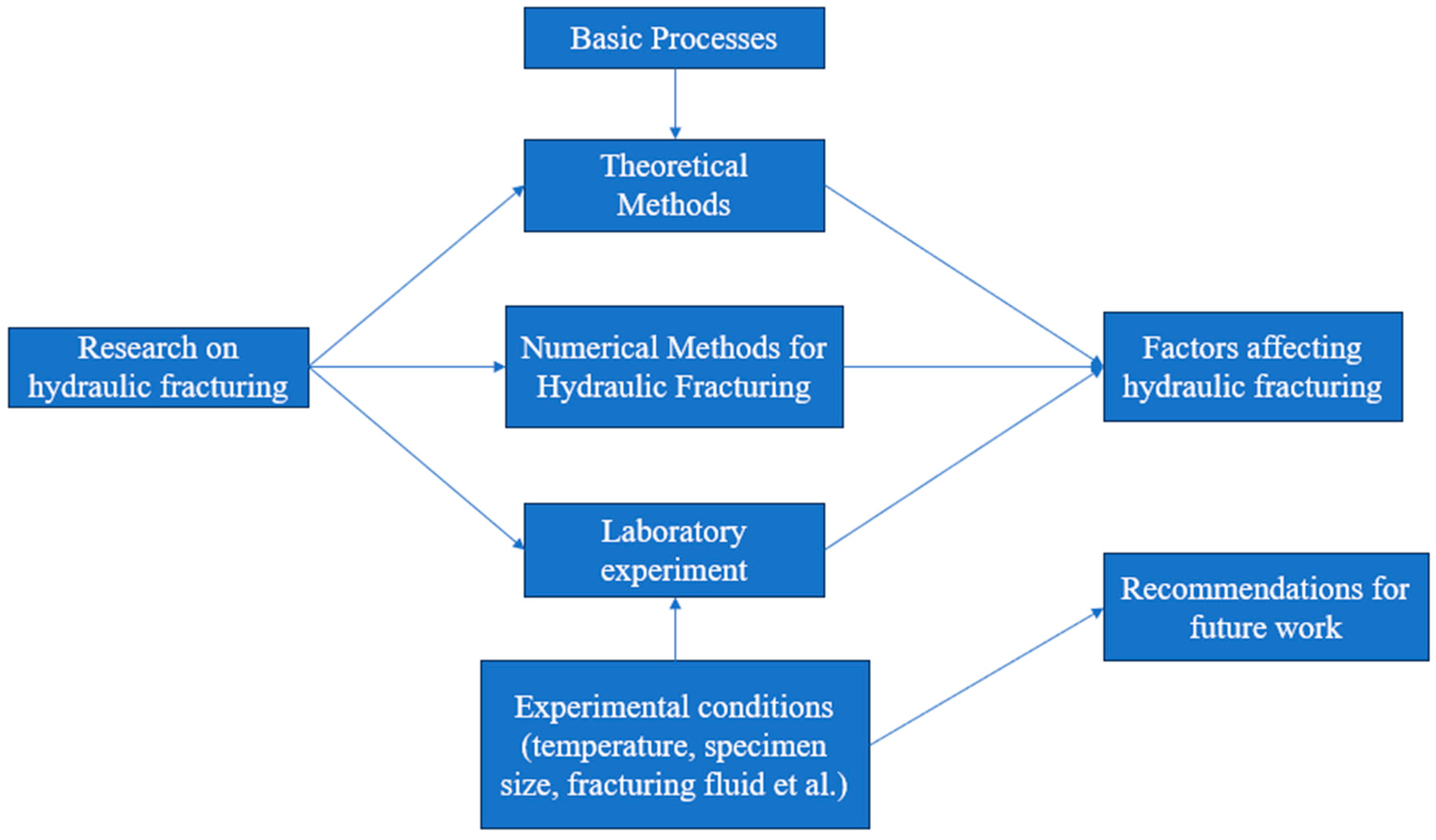
Therefore, this review aims to update the knowledge on hydraulic fracturing in geothermal systems, with a focus on experimental, theoretical, and numerical methods. It also provides insights into how to overcome existing limitations in this field. As shown in Figure 2, this review is structured as follows: Section 2 presents the experimental methods and conditions related to hydraulic fracturing, including sample preparation, testing environments, and fracturing techniques. Section 3 introduces the theoretical models of hydraulic fracturing, covering classical approaches like the PKN, the KGD, and other models. Section 4 delves into numerical models, which offer more accurate predictions of complex fracture networks. Section 5 focuses on the key factors that influence hydraulic fracturing effectiveness, such as stress conditions, fluid properties, and rock characteristics. Section 6 discusses the latest research progress. Finally, Section 7 highlights the remaining challenges, and proposes directions for future work.

2. Laboratory Methods for Hydraulic Fracturing

2.1. Specimens and Experimental Setup

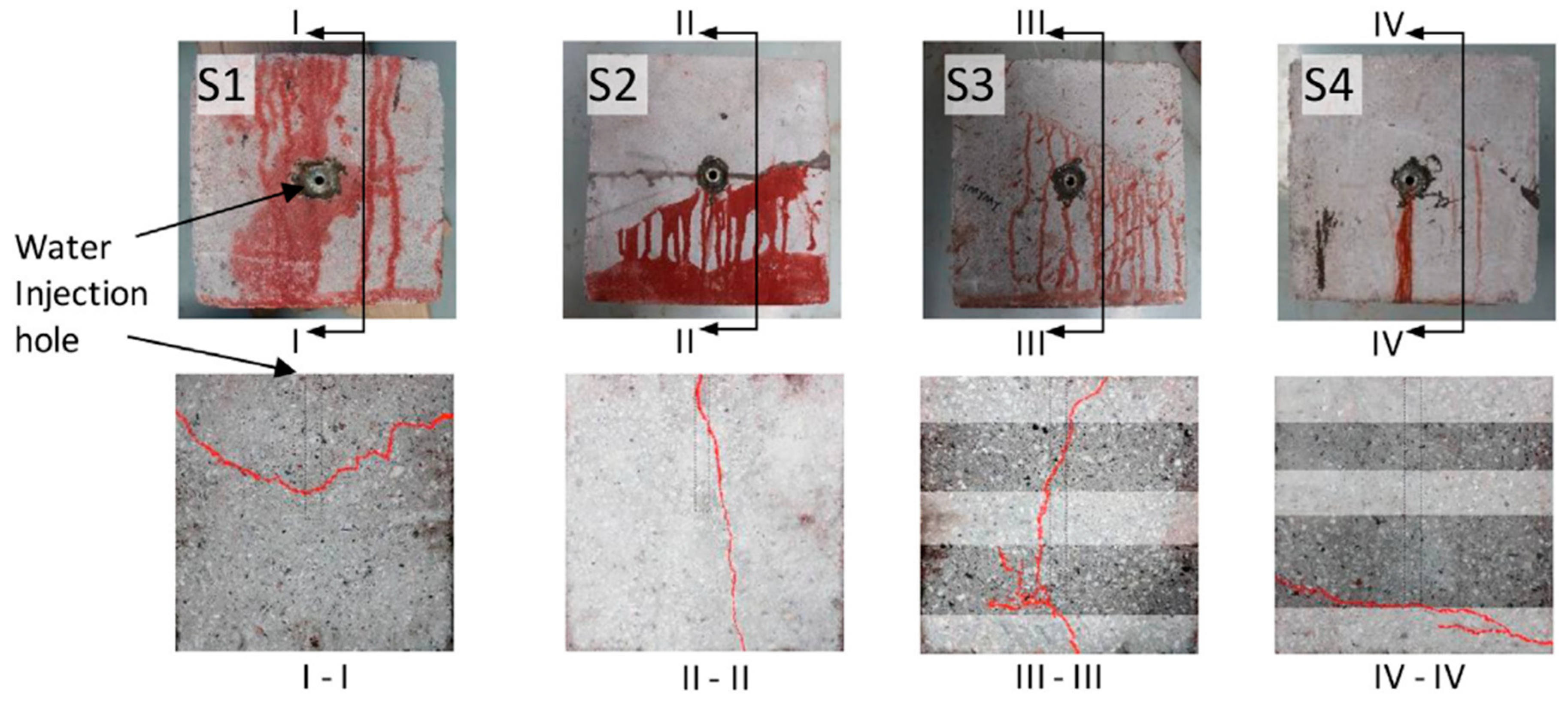
Before conducting a hydraulic fracturing experiment, sample preparation is essential. Ideally, the sample material should come from the in situ reservoir. However, extracting in situ reservoir samples can present significant challenges. As a result, near-surface rocks or artificial rocks are often used as substitutes in experiments [28]. The geometry of the sample—whether cylindrical, cubic, or rectangular—depends largely on the experimental setup. Typically, cubic or rectangular samples are used in true triaxial experiments, while cylindrical samples are more common in biaxial or uniaxial tests. The size of specimens used in hydraulic fracturing experiments varies significantly across studies. Larger rock samples are advantageous as they reduce boundary effects, allowing fracture propagation to more closely resemble field conditions [29]. The largest specimen (762 mm × 762 mm × 914 mm) to date was used by Fu et al. [29]. In true triaxial high-frequency tests, cubic blocks with side lengths between 100 mm and 300 mm are commonly employed [5]. Fracturing fluid is critical in these experiments. Commonly used fracturing fluids include water, slickwater, guanidine gum, various acidic solutions, supercritical water, and supercritical carbon dioxide [30,31,32,33,34]. Studying the properties of different fracturing fluids aids in understanding the evolution of rock fractures. For example, Shokir et al. [35] used a small glass model to investigate the transport and placement efficiency of proppants in four non-Newtonian fluids. To improve fracture visualization, tracers are often added to the fracturing fluids (Figure 3). Table 1 provides a summary of the sample types, fracturing fluids, and loading settings used in several hydraulic fracturing tests. The selection of experimental methods is guided by parameters observed in field hydraulic fracturing projects. For instance, since hot dry rock (HDR) reservoirs typically consist of granite, many experiments use granite samples to reflect field conditions. The type and injection speed of fracturing fluids are designed to match field practices. Sample dimensions comply with rock mechanics testing standards while considering the equipment capabilities of each laboratory. The choice of materials and fluids is tailored to replicate field-like fracture propagation. For example, a mixture of mineral oil, gypsum, and cement was identified as the most suitable combination for simulating fracturing fluids and formations [36]. To analyze the effect of natural fractures on fracture development in hydraulic fracturing, samples with pre-existing fractures were used [37]. A similarity criterion was employed to calculate simulated ground stress and fracturing parameters. For instance, the injection rate of 0.326 mL/s in laboratory experiments was designed to correspond to a field injection rate of approximately 12 m3/min [38].
To investigate the effects of pre-existing fractures on hydraulic fracture behavior and interaction patterns, samples containing such fractures have been widely used in laboratory experiments [20]. In that study, the authors created a block sample measuring 300 mm × 300 mm × 300 mm, embedding a piece of white paper (200 mm × 150 mm × 0.1 mm) to simulate natural cracks within the rock. Similarly, Tan et al. [40] used 0.11 mm thick coated paper to form bedding planes in coal and shale samples. Hadei et al. [41] conducted hydraulic fracturing tests on thick-walled cylinder samples with different thicknesses and inclination angles, aiming to study the influence of reservoir inclination angle on hydraulic fracturing fracture propagation. To further study the effects of temperature and injection rate of fracturing fluid on the fracture toughness of HDR, Zhuang et al. [42] conducted hydraulic fracturing tests controlled by temperature and injection rate.
The thermal effect plays a critical role in the evaluation of geothermal reservoir compressibility and cannot be overlooked [43]. To investigate the hydraulic fracturing characteristics of granite, Ma et al. [44] maintained the outer surface temperature of granite samples at 90 °C while applying four different levels of confining pressure. In a similar study, Luo et al. [45] first applied confining pressure to the rock and then used an electric heater to heat the sample, adjusting the outer surface temperature to 60 °C, 70 °C, 80 °C, and 90 °C. To prevent sample damage from uneven heating, the heating process was gradual. Tan et al. [46] conducted hydraulic fracturing experiments at 25 °C and 200 °C and maintained a constant heating rate. After reaching 200 °C, the samples were kept in equilibrium for 12 h. Despite the importance of temperature in hydraulic fracturing studies, few experiments have been conducted under high-temperature geothermal conditions, with most research limited to temperatures up to approximately 200 °C [47].
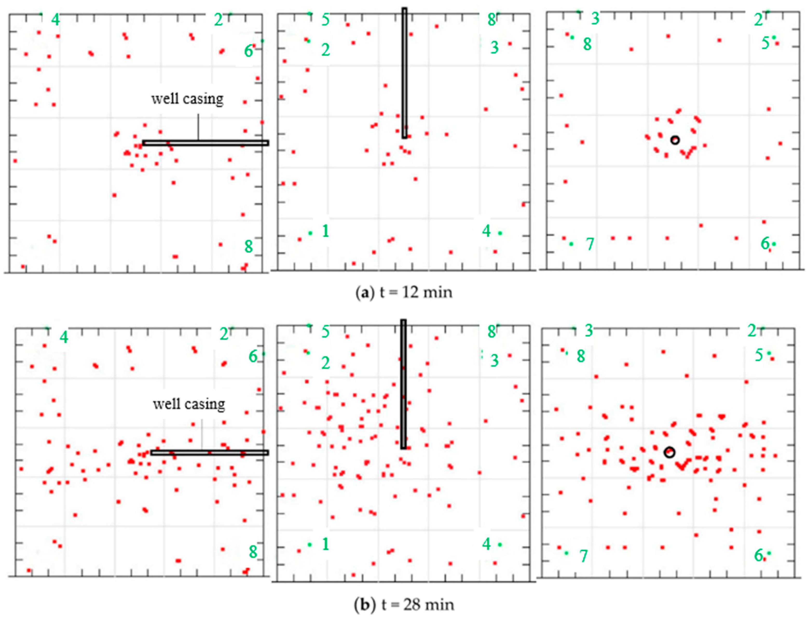
The acoustic emission (AE) system is highly effective in monitoring microfracture development in real-time, making it widely used in hydraulic fracturing experiments. Xing et al. [48] utilized AE technology to characterize the hydraulic fracturing process, revealing that while the fracture geometry remains largely unchanged at different temperatures, the injection pressure curve and the spatial distribution of AE changed significantly. To explore the relationship between multiple AE features and hydraulic fracturing injection pressure, Jiang et al. [39] recorded AE signals from four different specimen types during hydraulic fracturing under true triaxial stress using AE sensors. Guo et al. [49] monitored the fractures in the hydraulic fracturing process through acoustic emission probes. As shown in Figure 4, the AE system captures the number and location of fractures during the fracturing process. Additionally, Wang et al. [50] used a true triaxial rock mechanics test system combined with acoustic emission monitoring to investigate damage evolution in saturated rock samples under various stress levels. Zenchenko et al. [51] used ultrasonic transmission monitoring to observe crack propagation and opening and measure multi-point pore pressure in porous saturated samples.
Table 1. Some hydraulic fracturing test settings.
Specimen TypeRock TypeSpecimen Dimensions (mm)Borehole Dimension (mm)Applied Stress (MPa)Injection Fluid Type (MPa.s)Injection Rate (mm3/s)References
CylinderWesterly graniteD 50, H 1256.35σ1 = 30,
σ2 = 10
water0.016Goodfellow et al., 2015 [52]
graniteD 50, H 10010σ1 = 15,
σ2 = 5, 10, 15, 20
water0.2Ma et al., 2019 [44]
pyroxene andesiteD 35, H 703.5σ1 = 5,
σ2 = 6, 8, 10, 12, 14, 16, 18, 20
saturated brine1.75Sawayama et al.,
2021 [53]
Inada graniteD 30, H 251.5σ1 = 90, σ2 = 40water0.05Goto et al.,
2021 [47]
sandstone from Ordos BasinD 50, H 1255σ1 = 83, σ2 = 35.5water5Qin et al.,
2021 [54]
concreteD 53, H 10510σ1 = 1
σ2 = 0.6, 0.8, 1, 1.4, 2
oil0.05Rodríguez et al.,
2021 [55]
graniteD 50, H 1002σ1 = 10,
σ2 = 10
water0.004Zhang et al.,
2022 [56]
mixture of gypsum and cementD 43, H 6.616σ1 = 6.6,
σ2 = 1
mineral oil
0.12
0.17
0.2
Novikova et al.,
2023 [36]
Cubicconcrete blocks300 × 300 × 30010σ1 = 10,
σ2 = 6,
σ3 = 4
water0.058Yan et al.,
2011 [37]
shale outcrops300 × 300 × 30010σ1 = 20, σ2 = 10,
σ3 = 8
guanidine gum
2, 6.5, 15, 20
0.326Hou et al.,
2014 [38]
Longmaxi shale400 × 400 × 40016σ1 = 22.1, σ2 = 26.3, σ3 = 19.1water0.163~0.652Cheng et al.,
2015 [57]
concrete block300 × 300 × 30030σ1 = 6.5,
σ2 = 12,
σ3 = 11.5
water and guar gum,
1.35
0.2, 0.4Deng et al.,
2016 [58]
granite from Shandong300 × 300 × 30025σ1 = σ2 = σ3 = 0.1;
σ1 = 30,
σ2 = 25,
σ3 = 10
CaCl2 solution,
1
0.033Xing et al.,
2019 [48]
artificial carbonate
blocks
300 × 300 × 30020σ1 = 16,
σ2 = 14,
σ3 = 7
water-based guanidine gum solution,
10
0.333Liu et al.,
2019 [59]
granite and gabbro330 × 330 × 33020.1σ1 = 3.45,
σ2 = 10.34, σ3 = 6.89
NaCl solution,
0.002 mol/L
0.417Hu et al.,
2020 [60]
concrete block300 × 300 × 30010σ1 = 20, σ2 = 10, σ3 = 5;
σ1 = 27.7, σ2 = 13.8, σ3 = 6.9
gel solution,
16.5
0.326Zeng et al.,
2020 [32]
concrete blocks300 × 300 × 30025σ1 = 20, σ2 = 10, σ3 = 5;
σ1 = 28, σ2 = 17, σ3 = 7
Glycerin,
5.5
0.5Ali
2020 [61]
Inada granite100 × 100 × 10010σ1 = 40, σ2 = 15,
σ3 = 5
water0.15Goto et al.,
2021 [47]
granite outcrops in
the Gonghe Basin
200 × 200 × 20020σ1 = 18, σ2 = 12, σ3 = 6;
σ1 = 24, σ2 = 15, σ3 = 6
water0.083~0.333Liu et al.,
2022 [62]
granite150 × 75 × 2010σ1 = 20, σ2 = σ3 = 0water0.326Zhu et al.,
2024 [63]
granite outcrop in Gonghe Basin300 × 300 × 30022σ1 = 11.81,
σ2 = 7.87,
σ3 = 5.51
water0.5Tan et al.,
2024 [46]
granite from Luya
Mountain
200 × 200 × 20015σ1 = σ2 = σ3 = 25water1Yin et al.,
2024 [64]

2.2. Loading Scheme

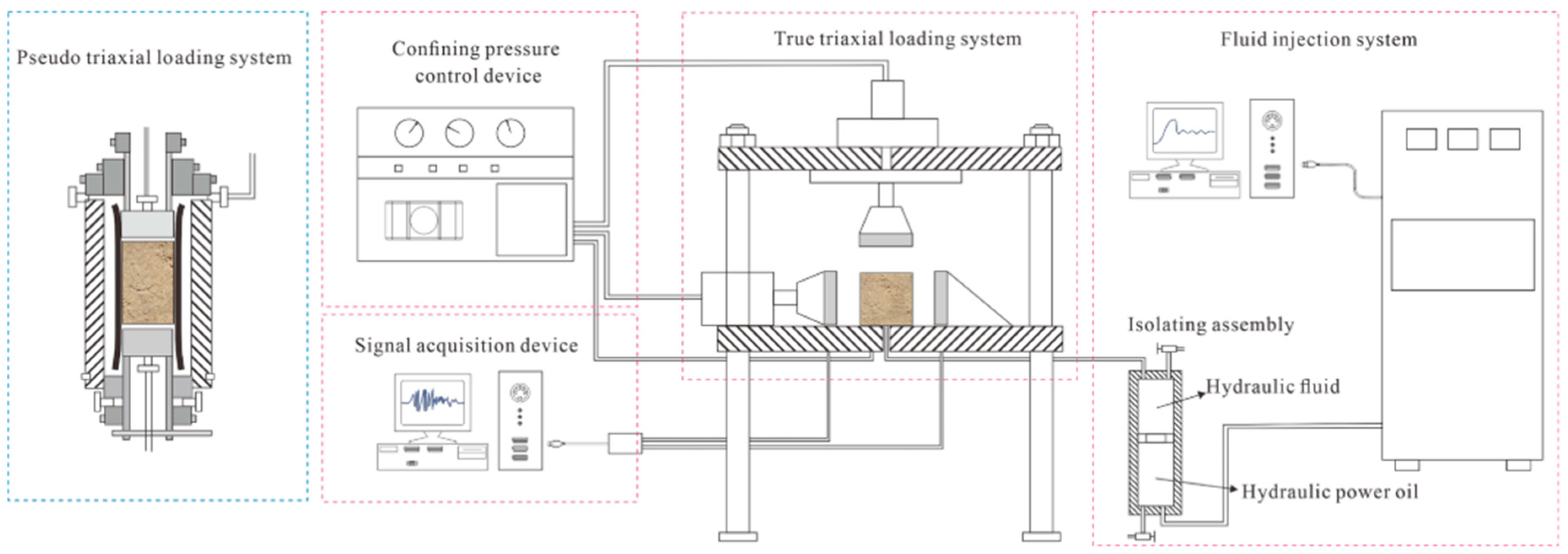
Experimental devices used to simulate hydraulic fracturing can be divided into three types according to loading methods: (1) uniaxial, (2) biaxial, and (3) true triaxial. In uniaxial tests, stress is applied only along the axis of the specimen, causing hydraulic fractures to expand randomly in the plane perpendicular to the loading direction [28]. Biaxial devices apply both axial and radial stresses, with two stresses being equivalent, which is why this method is also referred to as pseudo-triaxial testing. Unlike the pseudo-triaxial approach, true triaxial tests apply different stresses along the three orthogonal directions [65]. The distinction between true triaxial and pseudo-triaxial experiments is illustrated in Figure 5 [66]. Wang et al. [50] conducted a true triaxial test on off-white granite, wrapping the sample in a heat-shrink tube and applying lateral confining pressure. They used an ultrasonic velocity measurement system with longitudinal wave sensors placed at both ends of the sample to detect changes in the rock’s pore structure. Cheng et al. [67] studied hydraulic fracturing of large-size granite under true triaxial stress by simulating real HDR conditions. However, the experimental results are still affected due to the friction between the sample and the lower cover plate.
The mechanical behavior of rock under cyclic loading differs significantly from that under single loading [68]. Unlike monotonic loading, cyclic loading introduces variations in potential energy, giving the rock greater resistance to deformation. The stress-deformation of rough cracks becomes a critical factor in influencing the hydraulic performance of fractures under cyclic loading, with the hysteresis effect due to plastic deformation becoming more pronounced at high temperatures [69]. The stress-deformation of rough cracks becomes a critical factor in influencing the hydraulic performance of fractures under cyclic loading, with the hysteresis effect due to plastic deformation becoming more pronounced at high temperatures. To investigate the cyclic injection behavior, Liu et al. [62] conducted hydraulic fracturing tests under in situ stress conditions by controlling different cycles. Ghazanfari [70] studied the long-term effects of proppant-fracture interactions, applying 15 MPa of confining stress over five stages, holding each for 12 h. Wu et al. [71] studied the influence of “high-pressure duration + low-pressure duration” on tight sandstone under high-stress conditions and recorded the hydraulic fracture morphology and peak frequency under various conditions. Hu et al. [60] observed the effect of cooling on injection pressure, noting that continuous cold-water injection reduced pressure, indicating an increase in crack aperture due to thermal stress. Additionally, thermal cycling increases the fracture density in granite, leading to intergranular and intragranular cracking [72], with the extent and length of cracks growing as thermal cycles progress. Cyclic hydraulic fracturing has the potential to create more complex fracture networks, which can enhance the extraction of geothermal energy. Currently, it is significant to further develop cyclic hydraulic fracturing, especially in optimizing its application for geothermal systems.

3. Theoretical Methods for Hydraulic Fracturing

Hydraulic fracturing consists of three fundamental processes: (1) rock deformation, (2) fluid flow, and (3) fracture propagation [73]. This section examines hydraulic fracturing by analyzing each of these key processes using theoretical models, which are summarized in Table 2.

3.1. Basic Processes

3.1.1. Rock Deformation

Rock deformation is related to the material properties and boundary conditions of rock [74]. Additionally, rocks often exhibit discontinuities and anisotropic behavior. Typically, empirical formulas are used to describe the deformation behavior of rock mass. Assuming that rock mass behaves as a linear elastic material, the stress–strain relationship can be expressed as follows [74]:
σ = C : ε
where σ represents the Cauchy stress tensor, ε is the linear strain tensor, and C is the elasticity tensor.
The stresses causing rock deformation can be expressed as follows [75]:
· σ + ρ g = 0
This equation represents the equilibrium condition, where the divergence of the stress tensor ( · σ ) and the product of rock density ( ρ ) and gravitational acceleration ( g ) must sum to zero. It describes the balance between the internal stresses within the rock mass and the external gravitational forces acting on it.
The characteristics of the rock mass are assumed as follows: Geothermal reservoirs are homogeneous naturally fractured porous media, each of which is isotropic and linearly elastic in its initial state, taking into account the density and temperature-dependent properties of the fluids [76]. Therefore, the deformation of geothermal reservoirs can be regarded as the deformation of isotropic elastic materials [25]. The relationship between fracture pressure and opening length is given by the following [77]:
w = 2 h E p
where w is the fracture width, h is the fracture height, p is the fluid pressure and the E = E 1 v 2 , represents the plane strain modulus.
In a continuum-based approach, rock deformation is calculated based on a discretized grid. By contrast, in discontinuity-based methods, the deformation of the rock is represented by the movement of particles or blocks [77].

3.1.2. Fluid Flow in Fracture

Under laminar flow conditions, the fluid in the hydraulic fracture has viscous resistance, so the longer the distance from the injection point, the lower the fluid pressure in the fracture [22,23,27]. Based on mass conservation principles, Poiseuille’s law is commonly used to describe the relationship between pressure gradient and flow in hydraulic fractures. The Poiseuille flow equation is applied to the flow between two parallel plates, expressed as follows [78]:
q = w 3 12 μ d p d s
where q is the flow rate, w is the fracture width, μ is the viscosity of the fracturing fluid, p is the fluid pressure, and s is the local coordinate along the fracture’s tangential direction.
The fluid flow continuity is given by the following [78]:
A t + q x + q L = 0
where A is the cross-sectional area of the fracture and q L is the leak-off flow rate.

3.1.3. Fracture Propagation

According to the fracture propagation criteria and conventional energy methods, when the stress intensity factor near the crack tip reaches the threshold value, the fracture will expand and lead to vertical crack growth [79]. In stress intensity-based approaches, the crack spreads when the stress intensity of the crack tip exceeds the fracture toughness of the rock. Different numerical simulation criteria will lead to different fracture propagation modes. In discrete fracture models, the cohesive zone model (CZM) and linear elastic fracture mechanics are commonly applied, and the maximum tensile stress criterion is used [78,80].
The CZM differs from traditional fracture mechanics that rely on an infinitely sharp crack model. The main fracture is formed by the combination of microcracks along the fracture path [80]. In discontinuum-based methods, fractures are represented by bond breaks between particles or blocks, with fracture criteria implicitly defined by the bond-breaking rules [74,81].

3.2. Theoretical Methods

Over the past few decades, numerous hydraulic fracturing models have been developed, making significant progress in simplifying the complex geometry of fractures to address practical problems.

3.2.1. PKN Model

The PKN model was first proposed by Perkins and Kern [82], and later improved by Nordgren [83]. This model couples the plane strain elastic equation with the viscous fluid flow equation to calculate crack width. Initially, it did not account for fluid leakage into the rock matrix or fracture volume changes due to varying crack width, nor did it provide a formula for fracture length. Nordgren improved the model by considering one-dimensional fluid losses.
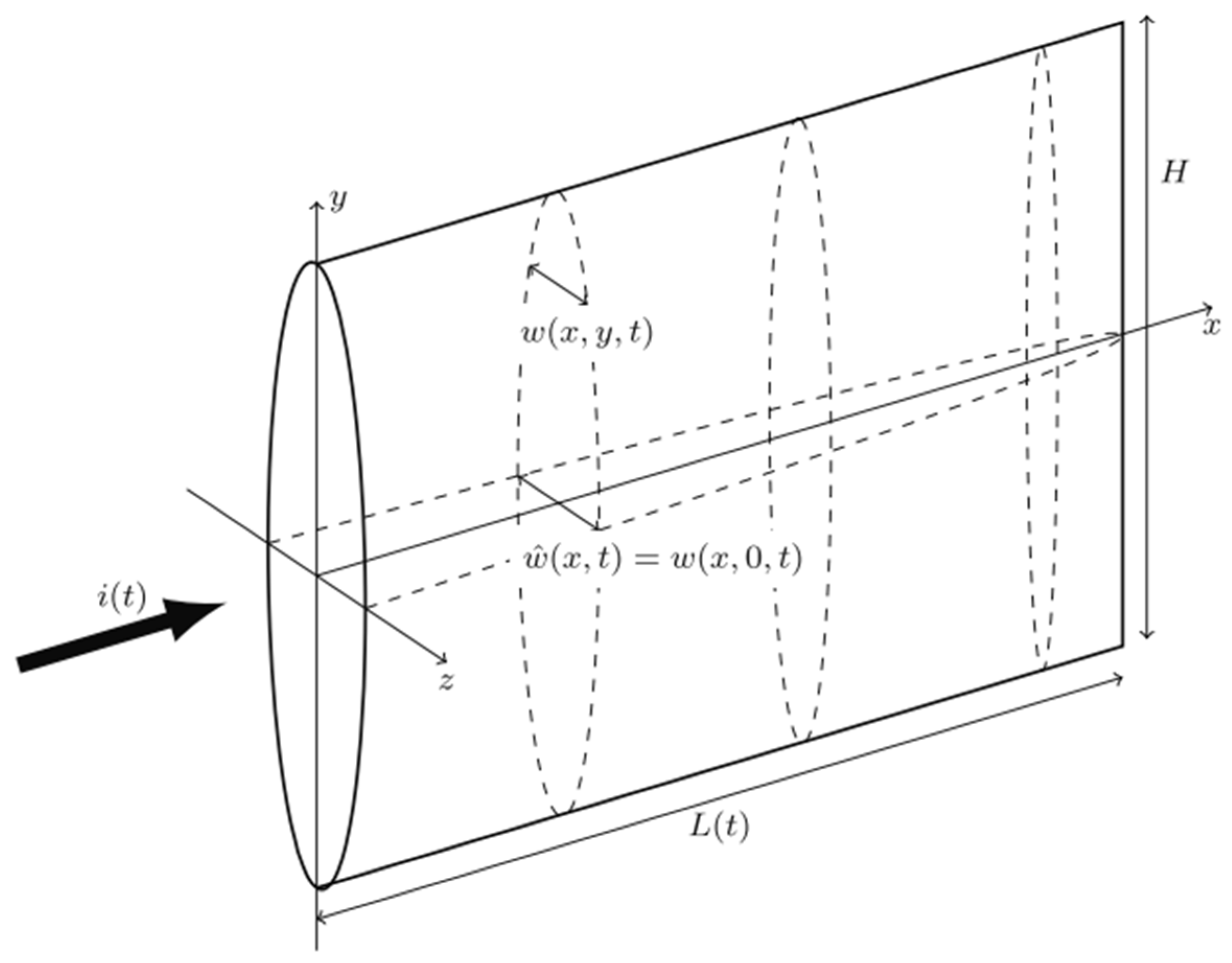
The PKN model is suitable for long cracks with elliptical sections [73]. It is based on the conservation of mass, relating injection volume, fracture volume, and fluid leakage [24]. A key assumption is that the fracture height remains constant (Figure 6), and the surrounding solid deformation remains small, with the material being linearly elastic and isotropic [23]. The model also assumes that, beyond a certain fracture distance, energy dissipation due to rock material toughness is negligible compared to that caused by fluid flow, making fracture propagation driven mainly by fluid velocity.
The fluid velocity in the PKN model is described by the following [23]:
v = 1 2 μ f p x ( w 2 4 z 2 )
According to the plane strain assumption of an ellipse, the fracture aperture is given by the following:
w = w ^ 1 4 y 2 H 2
where w is the fracture aperture and μ f is the fluid viscosity. w ^ is the maximum aperture at y = 0.
Despite the PKN model’s numerous assumptions, it provides a clear structural framework for hydraulic fracturing, capturing key dynamic features of fracture propagation. In naturally fractured shale reservoirs, hydraulic fractures may expand non-planarly when intersecting with natural fractures. Cheng et al. [57] proposed a non-plane expansion model based on the PKN model and rock fracture theory to address such complexities.

3.2.2. KGD Model

Geertsma and Klerk [84] improved the work of Khristianovich and Zheltov [85] by proposing the KGD model. Unlike the PKN model, the KGD model applies plane strain conditions to the horizontal cross-section, as shown in Figure 7.
The assumptions of the KGD model are as follows: (1) the formation is homogeneous and isotropic, (2) fracture deformation is linear elastic, (3) the fracturing fluid is purely viscous, without considering the influence of proppant, (4) fluid flow within the fracture is laminar, (5) the fracture cross-section is elliptical, and (6) fracture expansion occurs at any angle from the wellbore [86]. However, the KGD model does not account for the stress intensity effects at the fracture tip [75].
The mass balance within the fracture is governed by the continuity equation [87],
w t + q x = 0
where w is the crack opening, t is the time, and q is the average flow rate of fluid through the crack.
It is assumed that a Newtonian fluid with constant viscosity μ flows unidirectionally through the fracture in laminar form. The flow rate of the fluid can be expressed by the following [87]:
q ( x , t ) = 1 M w 3 p x
where M = 12μ and p is the fluid pressure.
Given that the pressure in most fractures is nearly constant, the maximum width of a hydraulic fracture at x = 0 can be determined as follows [75]:
w f ( 0 , t ) = 4 ( 1 v 2 ) L f ( p w f σ m ) E
Assuming a constant injection rate and no fluid leakage, the analytical solutions for the maximum fracture width and half-length are as follows [75]:
w f ( x = 0 ) = 2.360 ( i 2 μ E h f 3 ) 1 6 t 1 3
x f = 0.539 ( i 3 E μ h f 3 ) 1 5 t 2 3
where p w f is the bottom hole pressure, L f is the fracture length at the center, and E is Young’s modulus.
The KGD model has undergone several improvements to better reflect real hydraulic fracturing behavior. Carbonell et al. [88] kept the original KGD model’s plane strain conditions but modified the governing equations. Unlike the original smooth closure condition, the improved model incorporates a fracture propagation criterion based on LEFM theory, assuming the hydraulic fracture propagates in a moving equilibrium state [74].
w = 4 2 π K I E ( l x ) 1 2
K I = 2 l π 0 l P n l 2 x 2 d x
where K I is the mode I stress intensity factor and P n is the internal fluid pressure.
Dontsov et al. [89] applied the KGD model to study proppant transport in the presence of stress disturbances, successfully capturing the initiation and expansion of proppant plugs at the fracture tip, leading to tip screening. To address fluid-driven fracture propagation, Jin [90] proposed a fracture propagation criterion for states dominated by viscosity and ductility. The method reduces the number of iterations and improves the efficiency by linearizing and initializing the unknowns. Additionally, Jin et al. [91] introduced a smooth phase field to diffuse sharp fractures and cave edges, using an interleaved scheme that independently solves the pressure, displacement, and phase fields. Gracie et al. [92] extended these models by incorporating the effects of inertia and turbulence in fracture flow, applying the model to flows in channels between oscillating elastic plates.

3.2.3. Radial Model

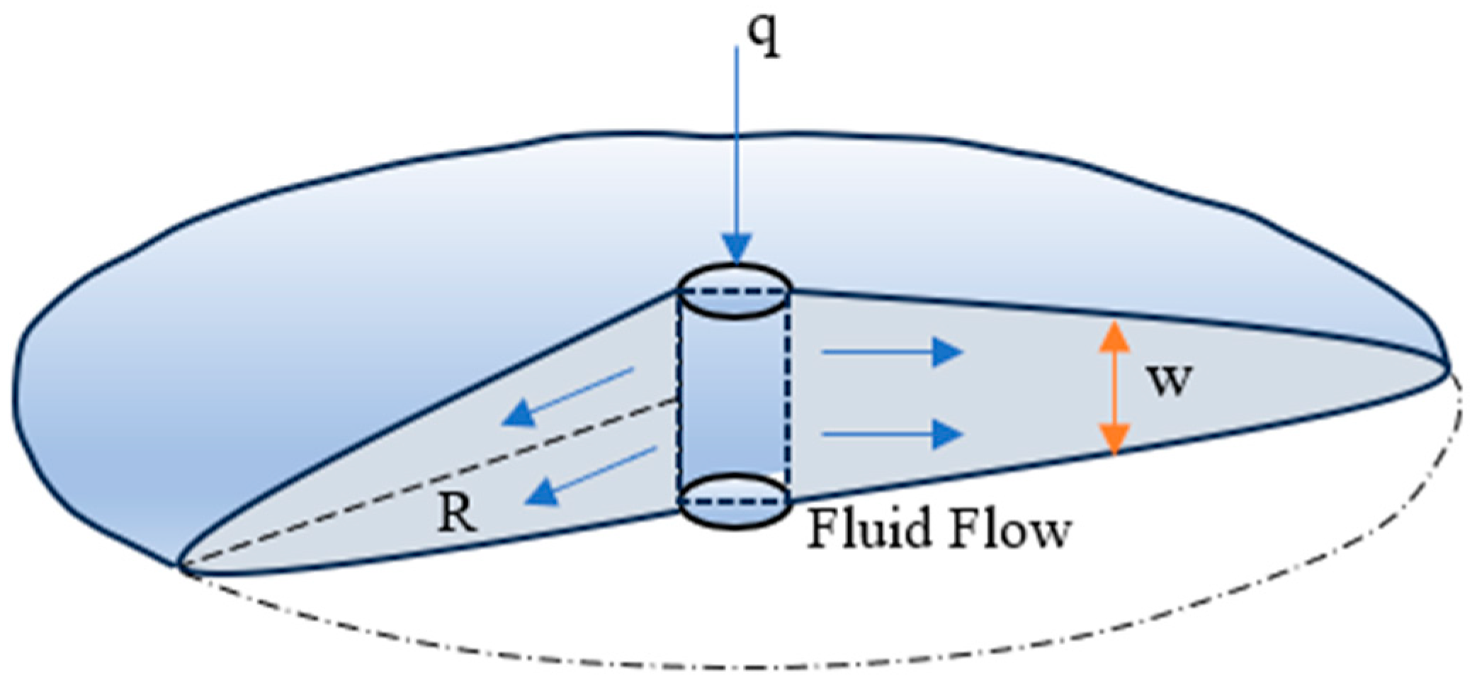
Due to the three-dimensional flow of the injected fluid, hydraulic fractures form a “penny” shape geometry, which is the radial model of hydraulic fracturing, as shown in Figure 8 [73]. In this model, the average fracture width is expressed as follows [75]:
w a v g = 0.279 [ μ × q i × ( 1 v ) × R E ] 1 4
where w a v g is the average fracture width and R is the maximum radius radial fracture.
Sneddon et al. [93] solved the radial model under conditions of constant fluid pressure and load. Geertsma and de Klerk [84] noted that the influence of fracture toughness becomes negligible for sufficiently large fractures. Detournay et al. introduced key assumptions for an asymptotic solution, including the following: (1) the wellbore radius is much smaller than the fracture radius, (2) fluid reaches the fracture tip, (3) fracture propagation occurs in a state of moving equilibrium, and (4) lubrication theory is applicable [94]. Viggiani et al. [95] used a radial model to solve the problem of power-law fluid injection to drive fractures in linearly elastic rocks with finite fracture toughness. Based on these models, Dontsov et al. [96] proposed a semi-analytical solution for turbulence-driven plane-strain hydraulic fracture propagation in impermeable formations.

3.2.4. Pseudo 3D (P3D) Model and Planar 3D (PL3D) Model

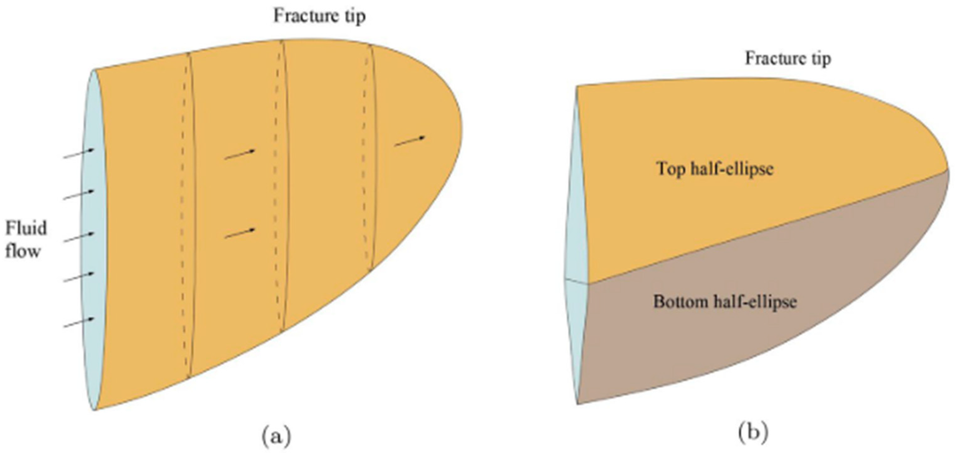
The traditional PKN and KGD models have limitations when applied to fully three-dimensional scenarios, particularly in addressing longitudinal fracture propagation. To overcome these limitations, the P3D model was developed based on the PKN model, which allows the crack height to vary spatially and temporally [97]. Depending on specific conditions, P3D models can be categorized as either lumped form or cell-based form, as illustrated in Figure 9 [74]. Key simplifying assumptions of the P3D model include: each vertical cross-section maintains a plane strain state, and the local crack height is determined by a balance between stress difference and rock fracture toughness [98]. The P3D model provides a more realistic description of hydraulic fracture growth in three dimensions compared to earlier 2D models, accounting for fracture height variations, which is crucial in heterogeneous formations.
Simonson et al. [99] combined linear elastic fracture mechanics (LEFM) theory with the concept of equilibrium fracture height growth in a three-layer, two-dimensional model. Based on this, Linkov et al. [97] introduced a correspondence principle that accounts for arbitrary stress contrasts and, combined with the KGD model, enhanced the traditional P3D model. Nguyen et al. [79] extended the classical P3D model to accommodate variable injection rates expressed as a power-law function of time. Additionally, Fomin et al. [100], using fractal geometry, developed a mathematical model for hydraulic fracturing, analyzing fracture mechanics simplistically and mapping fracture network connectivity on cubic regular grids.
To eliminate the elastic response assumptions of the PKN model, Clifton [99] proposed the Planar 3D (PL3D) model. This model calculates the critical fracture width for Mode I fractures using LEFM theory as follows [75]:
w c r i t = 4 K I ( 1 v ) G ( a 2 π ) 1 2
where a is a small distance in the order of the mesh size close to the fracture edge.
The Planar 3D (PL3D) model also considers thermal effects and proppant transport, though it requires higher computational costs due to the need for solving 3D elastic equations. Chen et al. [101] developed a PL3D fracture propagation coupled proppant transport model, using the fully explicit super-time-stepping method for computation. Yan et al. [102] introduced a connectivity algorithm for complex three-dimensional fracture networks, which, combined with the finite discrete element method, can directly simulate fluid-driven fracturing in any complex three-dimensional fracture network. By introducing the stress fracture criterion, Qin et al. [103] established a 3D hydraulic fracturing model based on cycle dynamics, using parallel computing to boost computational efficiency. Zia et al. [104] established a 3D hydraulic fracturing model based on cycle dynamics, using parallel computing to boost computational efficiency.
Table 2. Summary of theoretical models for hydraulic fracturing.
ModelAssumptionsCharacteristicReferences
PKNFracture height remains constant, surrounding solid deformation remains small, with the material being linearly elastic and isotropic. Beyond a certain fracture distance, energy dissipation due to rock material toughness is negligible compared to that caused by fluid flow, making fracture propagation driven mainly by fluid velocity.3D fracture geometry, elliptical vertical cross-section.[73,82,83]
KGDThe formation is homogeneous and isotropic, fracture deformation is linearly elastic, the fracturing fluid is purely viscous, without considering the influence of proppant, and fluid flow within the fracture is laminar.2D fracture geometry, rectangular cross-section.[84,85,86]
Radial ModelThe wellbore radius is much smaller than the fracture radius, fluid reaches the fracture tip, the fracture expansion is in a translational state, and lubrication theory is applicable.Hydraulic fracture in the shape of a penny.[73,75]
P3D ModelAll sections perpendicular to the expansion direction of the main fracture maintain plane strain state. The P3D model provides a more realistic description of hydraulic fracture growth in three dimensions accounting for fracture height variations.[97,98]
PL3D ModelPL3D eliminates the elastic response assumption of the PKN model.PL3D models can be implemented using either fixed or moving grid methods[99]

4. Numerical Methods for Hydraulic Fracturing

Predicting the geometry of hydraulic fracture zones and the variation in injection pressure throughout the fracturing process is critical for evaluating the effectiveness of hydraulic fracturing. Compared to the limitations of laboratory experiments, numerical simulation is more cost-effective for analyzing multi-field coupling processes in hydraulic fracturing. With the growing complexity of hydraulic fracturing models due to the exploitation of geothermal resources, various numerical methods have been applied to this field [105,106,107]. A key limitation of traditional models is that they often restrict hydraulic fractures to propagate along a straight line or planar plane [74]. Conventional fracture theory typically only addresses single-fracture propagation within reservoirs. However, numerous numerical simulation methods have emerged to solve the nonlinear partial differential equations associated with fracture propagation and fluid flow. These methods include the finite element method (FEM), the discrete element method (DEM), the finite–discrete element method (FDEM), and the boundary element method (BEM) [108]. A summary of numerical methods is listed in Table 3, which highlights their advantages and limitations.

4.1. Finite Element Method (FEM)

Classical finite element hydraulic fracturing models include the KGD model, the radial model, the 3D model, and the planar 2D model. Rawal et al. [109] utilized the FEM to model the transport process in fractures, incorporating a fractal geometry network model to simulate the fracture rock mass structure. To address computational cost issues in FEM simulations, many studies focus on optimization. Bao et al. [110] proposed a coupled FEM using condensation techniques to reduce computational expenses. This method eliminates irrelevant node displacements from the coupling equation, making it more efficient. Shauer et al. [111] proposed three key optimization schemes to improve the 3D hydraulic fracturing simulation algorithm using the FEM: (a) using pressure iteration to solve the 3D elastic problem; (b) improving the time step for crack expansion; (c) coupling the linear part of the stiffness matrix in a loop.
The FEM is widely applicable in various aspects of hydraulic fracturing analysis and simulation. Gee and Gracie [92] developed a dimensionally-reduced fracture flow model using the FEM, effectively capturing inertia effects and nonlinear fluid behavior. Deng et al. [58] simulated fracture initiation and propagation in directional hydraulic fracturing, analyzing the effects of notch angle, length, and injection speed. Ma et al. [112] used the FEM combined with a linear stress-displacement compression fracture model to study pore size variations in complex 3D discrete fracture networks. Chen et al. [113] applied the FEM to examine the mechanical behavior of rock matrices and fractures, assessing the impact of proppant and fracture layouts on geothermal development efficiency, and used a proppant embedding model to explore the evolution of fracture conductivity.
Hydraulic fracture propagation involves complex, nonlinear interactions between fluid injection and the creation of new fracture surfaces. Profit et al. [114] advanced a method to couple fluid-reservoir mechanical responses, using a dynamic geometry update approach for fracture insertion. Zhang et al. [115] employed a fully coupled synthetic rock mass model to investigate fluid-driven fracture propagation in naturally fractured rock. Cheng et al. [116] developed a numerical model for stimulating naturally fractured reservoirs, incorporating a thermo-pore elastic coupling framework to describe rock deformation, fluid, and heat flow. Zhao et al. [117] introduced a 3D thermo-hydro-mechanical coupling model to simulate geothermal energy extraction in hot dry rock, highlighting the dynamic changes in temperature, stress, seepage, and fracture aperture during heat recovery.
The FEM typically requires the mesh to conform to the fracture geometry in hydraulic fracturing simulations, limiting the fracture path to the pre-defined mesh structure [111]. One approach to address this issue is to reconstruct the grid at each propagation step to match the fracture geometry, though this increases computational costs. Another approach is to use a universal mesh that deforms at each step to fit the evolving fracture geometry [118]. To overcome these limitations, Belytschko et al. [119] introduced the extended finite element method (XFEM), which allows fracture problems to be simulated without the need for a conforming mesh. The XFEM achieves this by using discontinuity enrichment functions along the fracture path, freeing the fracture from the constraints of the standard element shape functions. Selected nodes around the crack are assigned additional degrees of freedom through these enrichment functions, as described by the following [119]:
u h ( x ) = I = 1 n N I ( x ) ( u I + j = 1 n E ( I ) a j I γ j ( r , θ ) )
where ( r , θ ) is a polar co-ordinate system with the origin at the crack tip and the x-axis parallel to the last segment and N I ( x ) is the standard finite element shape function. The enrichment a j I is associated with nodes and n E ( I ) is the number of coefficients for node I.
The main advantage of the XFEM is its ability to simulate fractures that propagate along arbitrary paths, unlike other methods that require predefined trajectories [120]. Ren et al. [121] applied the XFEM to simulate concrete hydraulic fracturing, deriving the governing equation based on the virtual work principle while accounting for water pressure on the fracture surface. Zheng et al. [122] developed an XFEM-based hydraulic model for impermeable rock structures, incorporating crack surface water pressure to derive the governing equations for hydraulic fracture simulation. Subsequently, Zheng et al. [123] proposed a nonlinear complementary model to address frictional elastic contact problems using the XFEM. By applying variational inequality theory, frictional contact conditions were represented as non-smooth equations, achieving high computational accuracy and enabling the simulation of adhesion and sliding of contact surfaces during hydraulic fracturing. To model the interaction between hydraulic and natural fractures, Xu et al. [124] introduced an enhanced XFEM, which accounts for the effects of fracture surface forces. This model uses enriched shape functions to capture the complex geometries that arise when fractures intersect, allowing for more realistic simulations of hydraulic fracturing in naturally fractured formations.

4.2. Discrete Element Method (DEM)

The DEM is crucial for simulating discontinuity problems in hydraulic fracturing, enabling the modeling of both particle interaction and the dispersion of a particle-based continuum. Zhou et al. [125] incorporated thermal stress effects caused by thermal expansion and contraction into the DEM, simulating hydraulic fracturing under varying temperatures and confining pressures. Wang et al. [126] developed an element partition method (EPM) coupled with the DEM to simulate particle migration within hydraulic fractures. This model effectively represents particle transport driven by fluid resistance and pressure gradients, capturing phenomena such as particle bridging and plugging. Torres et al. [127] combined the DEM with the elastic properties of rocks and the Mohr–Coulomb criterion to model hydraulic fracture initiation and propagation. Leonardi et al. [128] used the DEM to simulate mechanical interactions between particles and their movement in fracturing fluid, allowing for monitoring of hydraulic fracture propagation via particle vibration. Cao [129] combined the discontinuous displacement method of crack propagation with the Green function solution to avoid the discrete matrix field and significantly improve computational efficiency. Zhu et al. [63] advanced the DEM by integrating pressure and temperature fields to create a fluid–structure coupling model, investigating micro-hydraulic fracturing in granite blocks. This model incorporates a pore network search algorithm, increasing computational efficiency. Yang et al. [130] developed a discrete element model using the Edinburgh bonded particle model, combining it with computational fluid dynamics (CFD) to simulate hydraulic fracturing. This model explores fracture propagation under varying principal stress differences and investigates dual-hole synchronous hydraulic fracturing mechanisms. Yasin et al. [131] proposed an improved fracability index model, considering multiple parameters, such as brittle mineral composition, fracture toughness, minimum horizontal ground stress, brittleness, and temperature effects, to quantify rock fragmentation. Ju et al. [132] used a continuum-based discrete element method (CDEM) to simulate the hydraulic fracturing of heterogeneous conglomerates, accounting for hydromechanical coupling and fluid leak-off effects. The CDEM model, consisting of hydraulic fractures and micro-scale pores, utilizes Darcy’s law to control fluid leak-off, further enhancing its ability to simulate complex hydraulic fracturing scenarios.
The DEM models the rock matrix as a collection of discrete rigid blocks, with fractures between these blocks allowing fluid flow, making it suitable for fluid-structure coupling calculations in fractures [108]. However, one notable disadvantage of the DEM is its high computational cost [133]. In microscale or mesoscale problems, the particle size used to represent rock particles must be very small, leading to significant computational demands. Determining the optimal particle size parameters that effectively capture the volumetric behavior of the material remains a challenge [134]. Another limitation of the DEM is that the fracture network is represented by discrete particles, which lack the clarity of the grid surface representation commonly used in continuum-based methods [74].

4.3. Finite–Discrete Element Method (FDEM)

The FDEM is a hybrid approach that combines the deformation kinematics of the finite element method (FEM) with the discrete element method (DEM), making it particularly well-suited for simulating progressive fracturing in complex hydraulic fracture systems, such as those found in naturally fractured reservoirs [133,135]. However, the FDEM initially had limitations in simulating the full fracturing process of rock under hydraulic pressure. To address these issues, Yan et al. [136] proposed a hydraulic–mechanical coupling model based on the FDEM, enabling the simulation of hydraulic fracturing in complex fracture geometries. This led to the development of a new FDEM numerical code, “Y-flow”, for hydraulic fracturing simulations. Yan et al. [102] further enhanced the FDEM by creating the FDEM-flow3D model, which simulates hydraulic fracturing in three-dimensional, arbitrarily complex fracture networks. This model accurately replicates fracture propagation and water pressure changes during hydraulic fracturing, with the general fracture growth direction closely matching experimental results, even though fractures can only extend along solid unit interfaces. Zheng et al. [137] developed a seepage-stress-damage model to study fracture propagation influenced by formation interfaces. Wu et al. [138] combined the cubic law for fluid flow in fractures and Darcy’s law for fluid flow in the rock matrix, establishing a two-dimensional fully coupled model for porous media deformation and fracturing driven by fluid. Yan et al. [139] extended this further by proposing a coupled thermo-hydraulic-mechanical (THM) model, implemented in the MultiFracs software, to simulate rock cracking driven by multiple physical fields, including fluid flow, heat transfer, and fracture mechanics. Salimzadeh et al. [106] developed a coupled thermo–hydraulic model that considers the mechanical deformation of the rock matrix, applying it to study thermo-poroelastic effects in geothermal reservoirs with low permeability. The model includes parameters such as equivalent thermal expansion coefficients, which improve predictions of poroelastic effects in partially drained matrix formations.
Considering the heterogeneity of most reservoir rocks, it is necessary to study the relationship between rock heterogeneity and hydraulic fracturing by a numerical method. Lin et al. [140] integrated cohesive elements and pore pressure nodes into a solid grid to simulate progressive hydraulic fractures in heterogeneous rocks using the FDEM. Wu et al. [138] used the Weibull elastic modulus distribution heterogeneity model to conduct more realistic simulations and further discussed the influence of rock heterogeneity on hydraulic fracturing under ductile and viscous conditions.

4.4. Boundary Element Method (BEM)

The BEM is advantageous for hydraulic fracturing simulations because it only requires discretization of the boundary rather than the entire domain, which reduces the computational cost, particularly during dynamic fracture expansion. Behnia et al. [141] introduced a higher-order BEM to address hydraulic fracture propagation in stratified formations, applying a fracture tip element at each fracture end through the high-order displacement discontinuity method. To further this work, Behnia et al. [142] developed a numerical program (2DFPM) that studies the activation of natural fractures, using the maximum tangential stress criterion to predict hydraulic fracture (HF) propagation paths. In this model, tangential stresses under different contact conditions were calculated by combining finite difference methods with the BEM. Shi et al. [143] used the FRACOD3D program to simulate 3D fracture propagation under fluid pressure and thermal conditions. This program incorporates the displacement discontinuity method to simulate fracture propagation and the indirect boundary element method to model rock heat conduction. Zhou et al. [144] proposed a 3D coupled pore-thermoelastic model to analyze the effects of cold water injection in an EGS. Using boundary integral equations to handle the reservoir matrix’s fluid diffusion and heat transfer, this model avoids the need for full domain discretization. Ghassemi et al. [145] employed the displacement discontinuity method to develop a transient 3D numerical model coupling fracture flow and heat transfer with the thermal and pore-elastic deformation of rock matrices. Similarly, boundary integral equations were used to model pressure diffusion and heat conduction without discretizing the entire reservoir domain. Xu et al. [146] employed the displacement discontinuity method to develop a transient 3D numerical model coupling fracture flow and heat transfer with the thermal and pore-elastic deformation of rock matrices. Similarly, boundary integral equations were used to model pressure diffusion and heat conduction without discretizing the entire reservoir domain. He et al. [147] established a 3D fluid–structure coupling model for fracture propagation, using a modified BEM to calculate reservoir rock deformation during fracturing and accounting for the interaction between hydraulic and natural fractures. Chakra [109] combined the FEM with the BEM in a 3D model, using a displacement discontinuous BEM to calculate solid mechanics. Kebir et al. [148] applied the dual boundary element method (DBEM) to an incremental linear elastic crack propagation analysis, where the stress intensity factor is calculated for each crack increment using crack opening displacement at singular element matching points. Cheng et al. [149] combined a displacement boundary integral equation and a traction boundary integral equation to study the wellbore with a fracture network by using the DBEM.
The BEM simplifies the elastic problem by reducing it from a domain-based to a boundary-based discretization, offering simplicity and lower computational costs compared to other numerical methods [149]. However, it struggles with fracture mechanics problems involving complex 3D fracture intersections [148].

5. Factors Affecting Hydraulic Fracturing

Through the analysis of various hydraulic fracturing experiments and numerical models, several key factors affecting the hydraulic fracturing process are determined. Hydraulic fracturing works by the formation and propagation of hydraulic fractures to form a more complex fracture network with natural fractures, thereby increasing the permeability of HDR. Below is an analysis of the factors that influence the effectiveness of hydraulic fracturing.

5.1. HDR Matrix

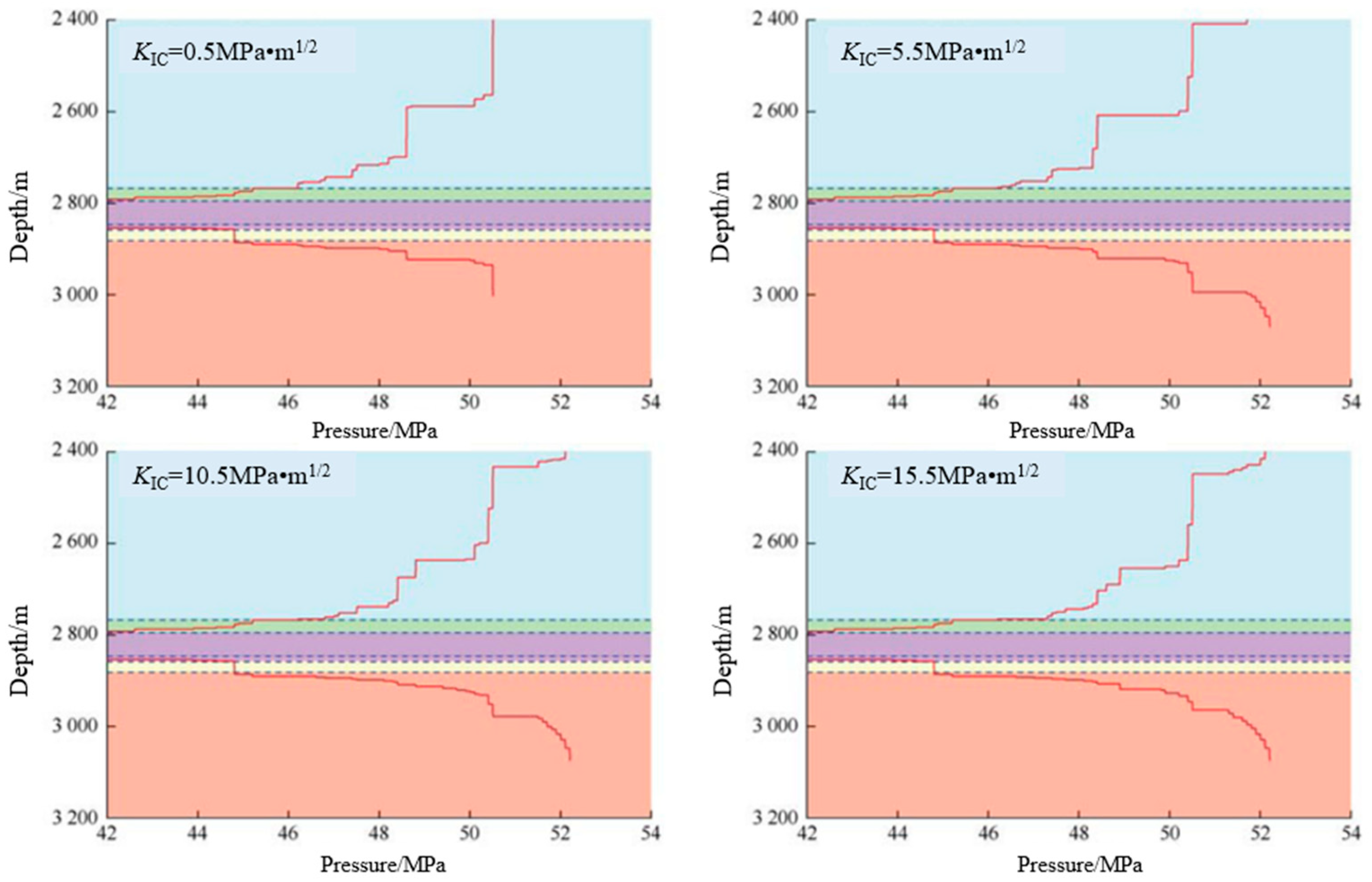
The HDR matrix significantly influences the hydraulic fracture process, with different rocks exhibiting varying responses. Mineral composition and particle size are critical factors that impact the hydraulic fracture path [21]. For instance, the saturation index of quartz decreases with rising temperature, whereas feldspar’s saturation index also declines, but in a different manner. These varied reaction mechanisms lead to distinct fracture deformation behaviors in different rock types [150]. In addition, compared with matrix thermal conductivity, permeability has a more significant effect on thermal recovery [151]. The more elastic the HDR, the more likely it is to form fracture networks, facilitating a more efficient hydraulic fracturing process. Intrusive rocks, compared to metamorphic and sedimentary rocks, generally exhibit a larger horizontal stress difference at the same depth, making the main fractures easier to extend to the desired depth [152]. Furthermore, fracture toughness is also closely related to hydraulic fracturing; higher fracture toughness results in greater deep closure stress and faster hydraulic fracture formation [153]. As shown in Figure 10, lower fracture toughness allows cracks to easily penetrate through the overlying layers, reaching the top boundary [154]. However, as the fracture toughness of the overlying rock increases, the fractures tend to propagate downward more prominently, with the lower fault tip becoming more pronounced.
The most critical factors influencing the hydraulic fracturing effect in layered reservoirs are the interface and adjacent layers arranged along the direction of hydraulic fracture propagation [41]. When a hydraulic fracture propagates along the permeability law, the fracture path remains consistent across the interface. However, when transitioning against the permeability law, shear slip may occur along the interface, potentially leading to fault propagation within the interface itself. In such scenarios, high hydraulic pressure can reduce the impact of inclined interfaces on the hydraulic fracture propagation path. Hydraulic fractures in stratified rocks deviate from the ideal orthogonal path, which hampers the formation of uniform fractures. However, these fractures offer a large convective heat transfer area, beneficial for geothermal energy extraction [155].
In stronger heterogeneous rocks, both the fracture pressure and the extension pressure are lower [156]. In a toughness-dominated regime (TDR), heterogeneity increases the unpredictability of how element size impacts hydraulic fracturing [138]. By comparison, under a viscosity-dominated regime (VDR), far-field stresses play a more significant role in hydraulic fracture propagation in a TDR. The minimum far-field stress exerts more influence than the maximum far-field stress, with more heterogeneous rocks exhibiting a stronger effect. The high mechanical heterogeneity in sedimentary geothermal reservoirs significantly influences fracture development, expansion, stimulation, and heat extraction in a sedimentary EGS [157]. This heterogeneity affects thermal recovery performance, where uneven fluid seepage is a primary cause of declining recovery efficiency [158]. Furthermore, non-uniform fracture roughness leads to uneven fracture apertures, altering flow paths and promoting cross-flow within the fractures [159,160].
Fractures serve as primary fluid flow channels within the reservoir [161,162]. Over a prolonged EGS operation, water–rock interactions may alter reservoir porosity, thereby affecting reservoir temperature and efficiency. The fracture aperture is a key determinant of fracture permeability [163,164,165]. Matrix deformation during hydraulic fracturing is influenced by pore pressure and reservoir temperature, initially decreasing and then increasing as the process unfolds [163]. Water velocity has the greatest impact on heat transfer, followed by fracture pore size and rock roughness, while initial rock temperature has minimal influence [166]. On a vertical plane, fracture geometry exhibits strong asymmetry, with non-planar and unilateral expansion. A higher vertical stress difference coefficient and increased injection rate lead to larger vertical fracture extensions [40]. However, vertical and inclined fractures can accelerate thermal breakthroughs, which negatively affect geothermal energy development [162]. Because hydraulic fractures interact with natural fractures, the stress field around the fractures also changes [167]. Additionally, fracture spacing influences the complexity of fracture networks and affects the low-temperature zone within hot dry rock reservoirs [168].
Under identical temperature and flow conditions, the heat transfer in smooth and rough fractures exhibits significant differences. The rough fracture has a larger surface area for heat transfer than the smooth fracture, resulting in higher total heat extraction from rough fractures [45]. While the total heat extracted from the parallel plate model is more than that from the rough fractures, the difference between the two decreases as the average fracture aperture increases [169]. In fractures with high flow velocities, thermal breakthroughs occur more readily, and the significant temperature difference between smooth fractures and the surrounding matrix promotes heat exchange [170]. Moreover, smooth fractures experience smaller pressure differentials.
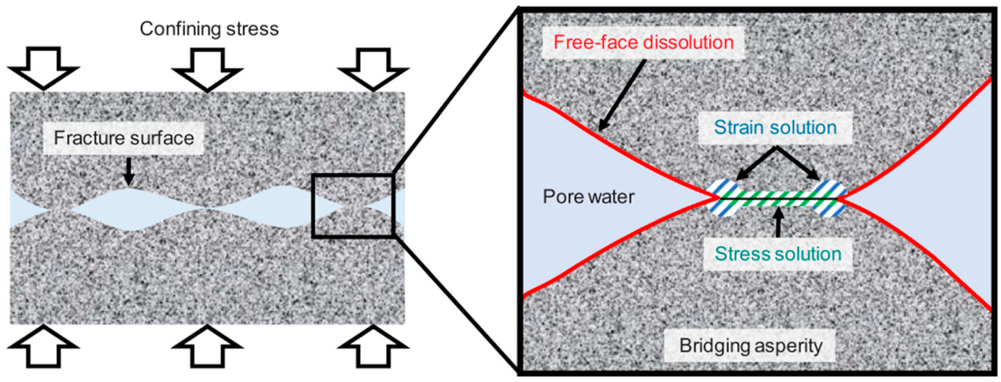
In thermal recovery processes, the hydraulic fracture’s priority differs based on temperature and flow characteristics. Low-temperature water preferentially flows through high-permeability hydraulic fractures toward production wells [171]. Over time, permeability may decrease due to pressure dissolution on the fracture surface, or it may increase due to free surface dissolution, as depicted in Figure 11 [172].
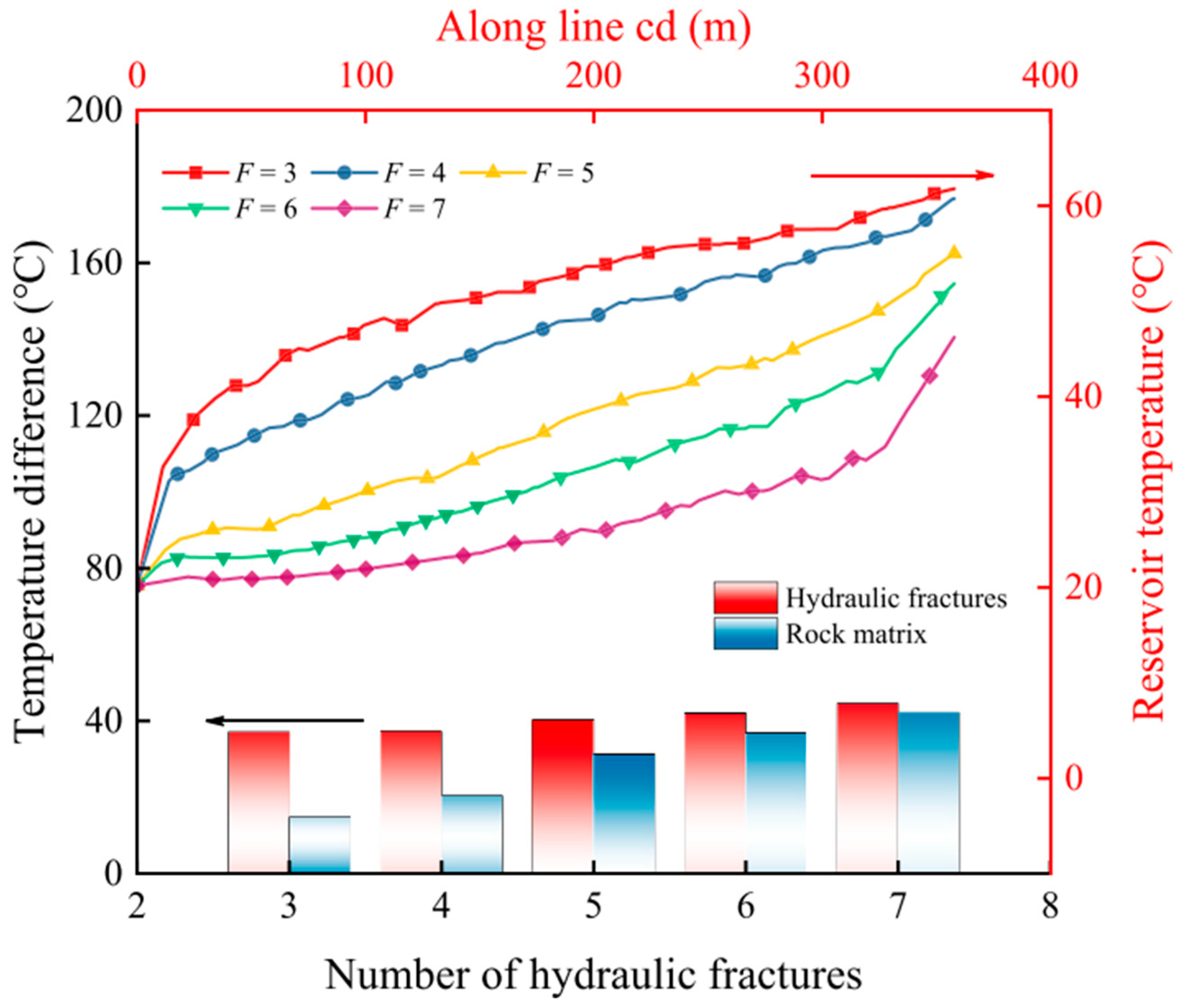
Increasing the number of fractures can enhance heat extraction. However, an excessive number of fractures can also accelerate thermal breakthroughs [173]. Chen et al. [174] studied the relationship between fracture quantity and heat exchange within rocks, and their findings, shown in Figure 12, indicate that a higher number of fractures improves the heat exchange efficiency.
Rock deformation and the fracture network significantly affect the heat recovery process in a multi-well EGS [33,175]. Fluids primarily flow through fractures directly connected to side wells, leading to thermal breakthroughs occurring first in these pathways. Changes in temperature and pressure fields induce effective stress, increasing fracture permeability and hastening thermal breakthroughs.

5.2. Temperature

Temperature plays a crucial role in hydraulic fracturing by influencing the degradation of thermal stress and tensile strength. Higher initial rock temperatures, along with larger surface heat transfer coefficients, contribute to the development of more complex fracture networks [176,177]. Hot rock possesses significant heat storage capacity, enabling a prolonged, high rate of heat extraction when cold fluid flows through the fractures [178]. For temperatures up to 300 °C, breakdown pressure decreases as temperature increases; however, above 300 °C, breakdown pressure remains relatively constant (Figure 13) [64]. This reduction in breakdown pressure at lower temperatures is primarily due to the decrease in tensile strength as temperature rises [31].
The initiation location of hydraulic fractures in fractured and filled granite is also temperature-dependent [64,179]. At 200 °C, hydraulic fractures tend to initiate within the backfill; whereas at temperatures above 300 °C, they initiate near the cementation interface. Tomac [180] explored the micromechanical effects of temperature differences between the fracturing fluid and rock, finding that thermally-induced fractures are generally shorter but wider than mechanically-induced fractures, resulting in adjacent parallel microfractures and parallel fluid flow reservoirs (Figure 14). Under thermal stress at around 200 °C, more fractures form perpendicular to the minimum ground stress, and with increasing injection pressure, these fractures can be connected to form a fracture network [181]. At high temperatures, thermal stress inside the rock matrix generates fine thermal cracks at grain boundaries, reducing the rock matrix’s strength [67,182]. For instance, at 100 °C, fractures form perpendicular to the minimum ground stress but remain largely unconnected, with a significant decrease in crack density. At extremely high temperatures, hydraulic fracturing may become less feasible due to the dominance of natural shear fracturing mechanisms [183]. In ultra-hot geothermal environments with temperatures ranging from 400 °C to 500 °C, an extensive permeable fracture network forms throughout the rock mass, referred to as the “cloud fracture network” [47].
There exists a strong coupling between temperature, thermal stress, and the permeability of thermal reservoirs [184]. As fluid extracts heat from the rock, the matrix cools, leading to shrinkage and deformation. This cooling induces thermal stress, which transforms into tensile stress, causing fractures to expand and increase the permeability of the reservoir. However, in the absence of fluid pressure, fractures will only propagate if the temperature difference between the fracture surface and the surrounding rock is sufficiently large [143]. High temperatures can also reduce the effective fracturing volume and diminish the overall effectiveness of hydraulic fracturing [48]. At lower temperatures and under high deviating stresses, brittle microfracturing is more common. However, as the temperature increases, or if the applied stress decreases or is sustained over an extended period, the failure mode transitions from brittle fracturing to transgranular and intergranular creep fractures, reflecting a shift from a brittle to a more ductile behavior [185].

5.3. Natural Fracture

Natural fractures in rock masses play a crucial role in shaping the behavior of hydraulic fracturing. In naturally fractured reservoirs, geological discontinuities of various scales create the potential for complex fracture networks, as opposed to simple, planar fractures commonly seen in less fractured rock masses [57,115]. Under the action of hydraulic fracturing, natural fractures may have shear slips, so the spatial arrangement of natural fractures becomes an important factor in determining the complexity and behavior of the overall fracture network [186]. The propagation of fractures usually follows the direction of the maximum principal stress, but existing natural fractures may also affect this propagation. Therefore, the location of natural fractures is a key parameter that affects the complexity of the fracture network during hydraulic fracturing [113,142,187]. While mechanical properties like tensile strength and Young’s modulus affect the aperture of hydraulic fractures, reservoir rock properties tend to exert less influence on the overall hydraulic fracturing outcome than the natural fracture development and the in situ stress conditions [187]. For intact or high-strength reservoirs, forming a complex fracture network that integrates natural fractures can be particularly challenging [188]. This challenge makes the assessment of rock’s physical and mechanical properties a difficult but important aspect of hydraulic fracturing technology.
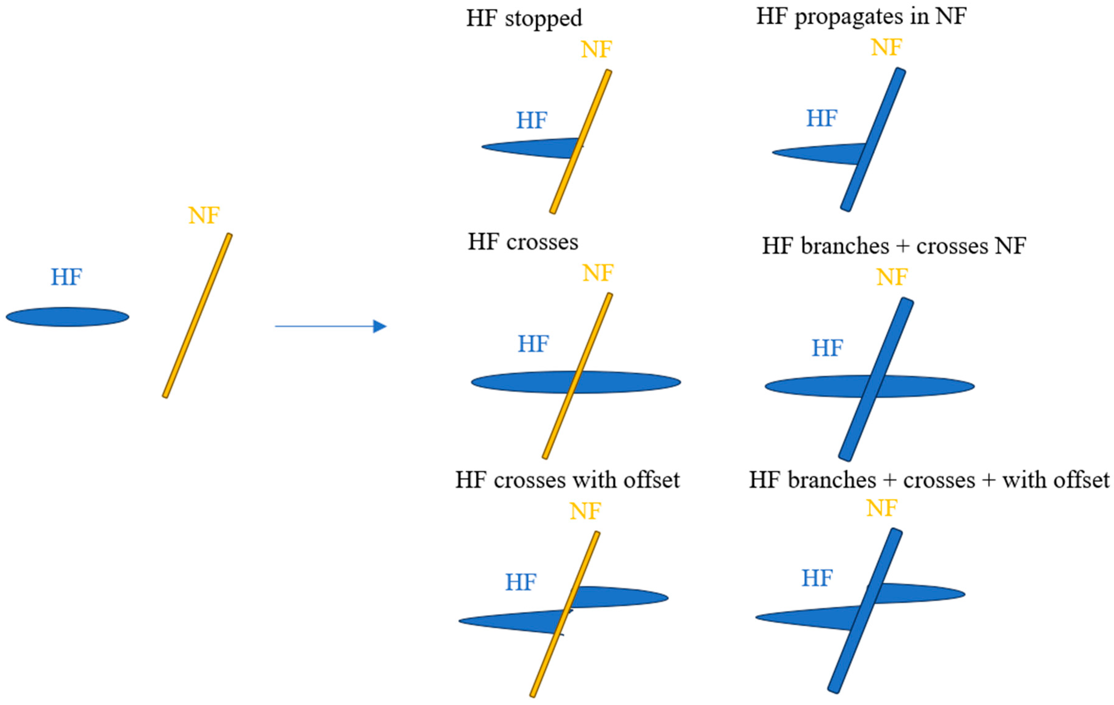
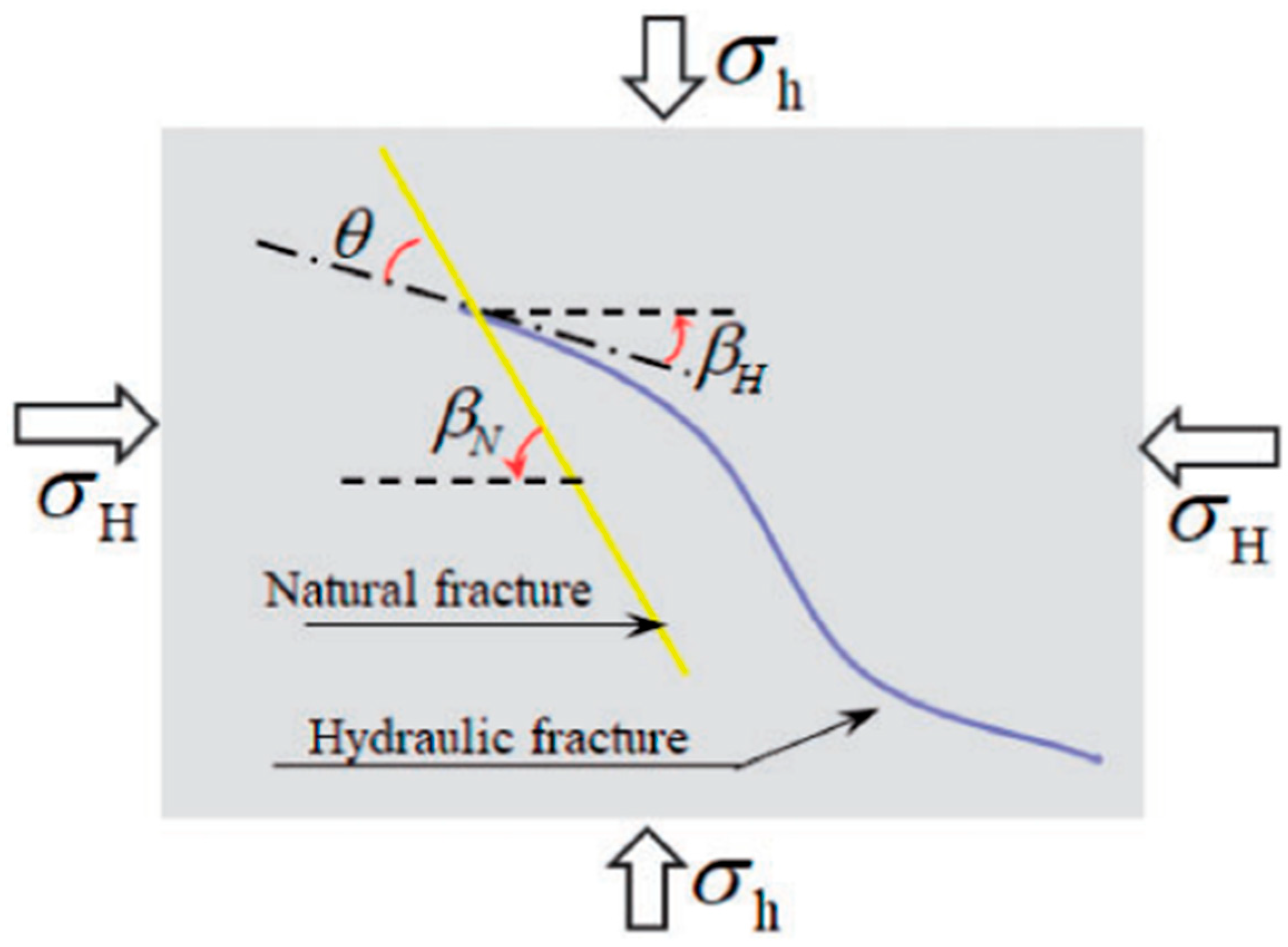
The interaction between hydraulic and natural fractures can occur in various modes, such as (1) network crossover, (2) network opening, (3) network opening, and (4) network opening crossover [29,61]. The failure behavior of pre-existing fractures in relation to hydraulic fractures depends on the interaction mode. When a natural fracture impedes the hydraulic fracture, shear failure may result due to slippage or expansion. On the other hand, when a hydraulic fracture intersects an existing fracture, it may close, branch, or continue expanding, often leading to tensile failure [189]. In most enhanced geothermal systems, the dominant process is the expansion of pre-existing fractures, though new fractures may also form in some instances [190]. The interaction between hydraulic fractures and natural fractures can result in various outcomes, such as arrest, intersection, or branching, as depicted in Figure 15 [191]. Understanding these interactions is key to predicting and controlling fracture propagation in naturally fractured reservoirs.
The interaction between natural fractures and hydraulic fractures, especially during cold water injection, can significantly promote fracture propagation, but also adds complexity to the fracture network. Natural fractures can twist and divert hydraulic fractures from the direction of maximum horizontal stress, leading to fracture diversion and branching. While this increases the complexity of the fracture network, it can also result in fluid leakage and hydraulic energy loss, making certain formations with numerous natural fractures less favorable for comprehensive hydraulic fracturing operations [26,40,192]. Natural fractures, along with hydraulic fractures, serve as the primary channels for heat transfer, which determines the efficiency of heat extraction in geothermal systems. Extending the recovery length of intersecting fractures is advantageous for heat production without necessarily increasing the aperture of these intersecting fractures [193,194]. The density, distribution, and size of natural fractures, as well as their hydraulic aperture, are key factors that influence the efficiency of hydraulic stimulation and the resulting fracture network [195].
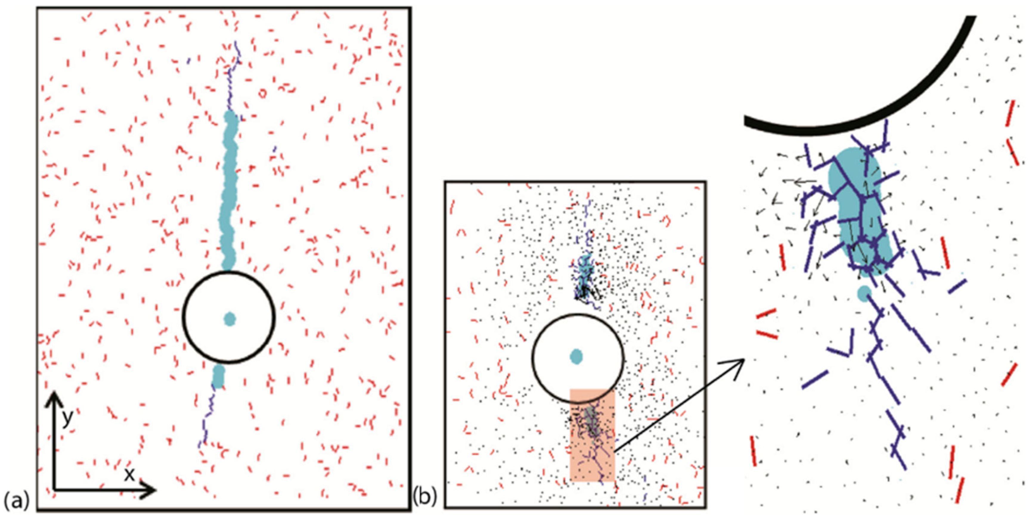
After hydraulic stimulation, staggered natural fractures can self-support, forming a network that enhances heat transfer, particularly when stress-shielding occurs in the reservoir. In these conditions, longer fracture networks form, providing more extensive pathways for fluid flow between injection and production wells, and increasing the effectiveness of heat extraction [196]. However, significant differences in fracture behavior are observed between vertical and horizontal wells. For instance, the vertical extension ability of fractures tends to increase as the vertical stress difference coefficient rises [40]. When natural fractures and hydraulic fractures are aligned vertically in a reservoir, hydraulic fractures may bend to intersect with natural fractures, leading to the formation of complex networks, such as radial, cross-shaped, or T-shaped fractures (Figure 16) [32,38]. In larger-scale samples, these interactions can result in spindle-shaped fracture networks when hydraulic fractures connect with multiple bedding planes (Figure 17).
In general, understanding the interaction between natural and hydraulic fractures can help improve geothermal energy extraction and mitigate problems such as fluid leakage and energy dissipation.

5.4. Fracturing Fluid

When cold water is injected into a hot geological formation during hydraulic fracturing, it increases pore pressure, leading to thermal fracturing [3,197]. This process is governed by the thermomechanical response of porous media to thermal strain, which is described by the following [3]:
σ + k p I = E : ( ε ε θ )
where E is the drained elastic tensor, ε θ is thermal strain, ε is total strain, k p remains constant during cooling, and I is second order identity tensor.
The fracturing fluid can transfer heat to the producing well, so the flow rate of the fluid directly affects the heat transfer efficiency [198]. In hydraulic fracturing of HDR, a reduction in the injection flow rate significantly weakens the fracture toughness of rocks like granite [42]. The breakdown pressure generally increases in proportion to the injection flow rate when the confining pressure and temperature are constant [67,137,199]. The injection rate is proportional to the fracture growth rate, with lower injection rates requiring a longer duration for fracture propagation [186,200]. The lateral propagation of hydraulic fractures is strongly influenced by the injection rate, while vertical and longitudinal propagation are less affected. An increase in injection speed results in higher fracture propagation pressure, larger fracture areas, and greater fracture width, but excessive flow rates can negatively affect heat transfer efficiency [79,140,201].
Proppants are introduced into hydraulic fractures during fracturing operations to maintain the fracture opening once the pumping pressure is reduced. Therefore, the properties and migration behavior of the proppant within the fracturing fluid play a crucial role in determining the final geometry and conductivity of the fracture [202]. Suri et al. [203] utilized the Eulerian-granular model combined with the computational fluid dynamics–discrete element model (CFD-DEM) to investigate how fluid viscosity and fracture width impact proppant behavior. Their findings revealed that smaller-diameter proppants tend to remain suspended within the fluid, while larger proppants settle more rapidly. Furthermore, high-viscosity fluids hinder proppant deposition and, in narrower fractures, proppant tends to deposit more quickly [204]. In formations with extensive natural fractures, water-based fracturing fluids are more effective; while in dense, intact formations, gel-proppant fracturing is preferable. The use of proppants also has the benefit of reducing the required injection pressure and mitigating the risk of seismic activity induced by hydraulic fracturing [70]. However, shorter fractures tend to exhibit higher pressures and smaller pressure gradients compared to longer fractures, and the rapid settling of proppants in short fractures can diminish the overall conductivity of the fractures [205].
Cold water injection during hydraulic fracturing induces fracture initiation and propagation by reducing tensile strength, introducing thermal stress, and increasing pore water pressure [176]. The cooling effect significantly lowers the pressure required to initiate fractures and promotes the formation of more cracks, resulting in a more complex fracture network [32]. At higher injection rates, cooling induces microfractures, reduces fracture pressure, and increases fracture complexity. By contrast, lower injection rates produce a weaker cooling effect, resulting in less complex fractures [46].
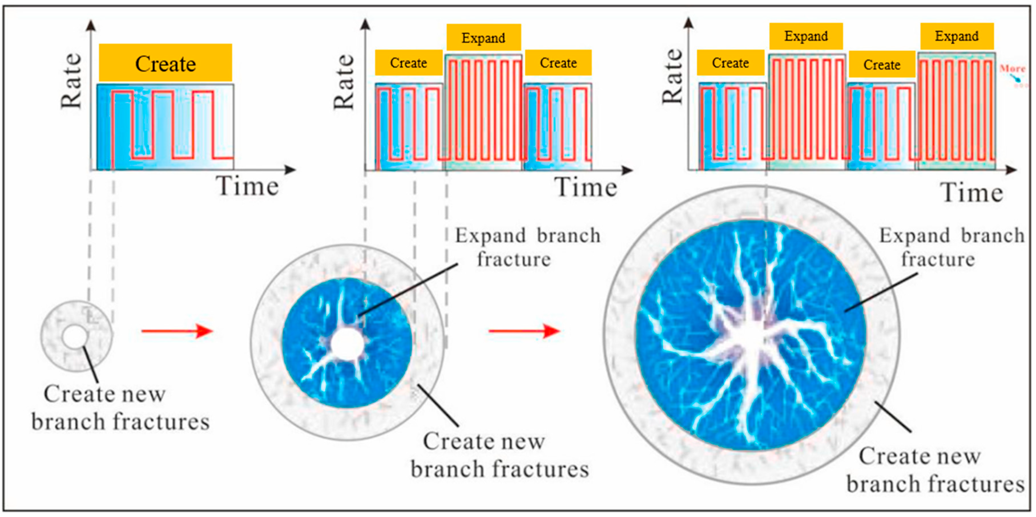
Cyclic hydraulic fracturing can reduce the breakdown pressure of granite by up to 20%, enhancing fracture formation [21]. The initiation and propagation of hydraulic fractures during cyclic injection are influenced by cycle duration and injection rate [62]. At low injection rates, high-frequency cyclic injections create a complex, shorter fracture network. At higher injection rates, both high and low cycle frequencies result in simpler fractures with greater extension potential. In practical applications, it is recommended to begin hydraulic fracturing with low-frequency injections. This encourages the formation of more branch fractures, increasing fluid flow channels. Subsequently, high-pressure injections can be used to extend the fractures further, creating a primary hydraulic fracture network that enhances fluid flow and heat transfer efficiency (Figure 18).
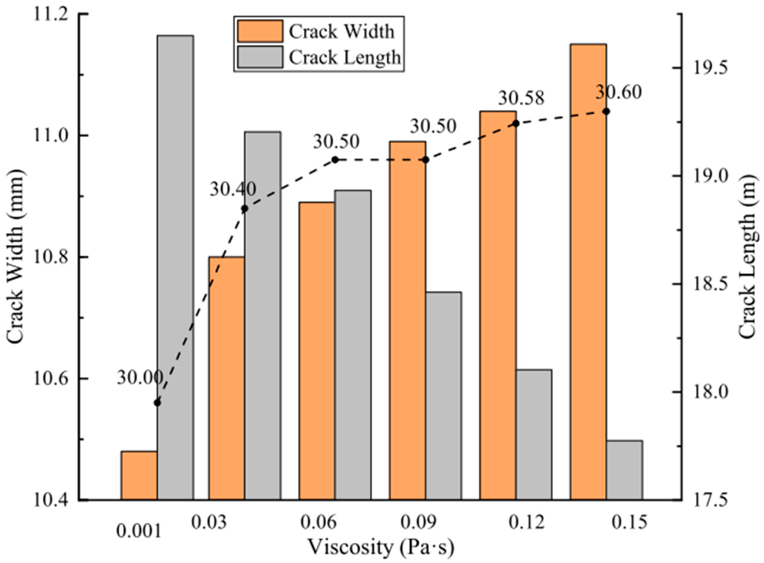
High temperatures, high injection rates, and the use of high-viscosity fracturing fluids tend to result in more complex failure patterns, promoting the formation of multiple hydraulic fractures [125]. Additionally, the introduction of temperature differentials, low displacement, and alternating cyclic injections facilitates the stimulation and development of intricate fracture networks [206,207]. Increasing the density of fracturing fluid also enhances fracturing effectiveness [154]. However, while high-viscosity fluids generate higher pressure and greater flow resistance, leading to an increase in the vertical pressure gradient and making longitudinal fracture propagation more challenging, they can reduce the overall fracture length, as shown in Figure 19 [152]. Interestingly, the viscosity of fracturing fluids has minimal impact on fracture complexity [206]. Acoustic emission studies indicate that fluid saturation enhances the initiation, propagation, and development of microcracks in rock samples [50]. In scenarios with uniform fracture apertures, the energy produced by carbon dioxide injection exceeds that of water under equivalent injection energy [208]. However, under conditions of high temperature, high pressure, and variable fracture apertures, a water-based EGS extracts more energy compared to CO2 [30]. The dissolution and precipitation of silica significantly influence the mechanical pore size and fracture permeability [209]. With the continued injection of fluid, the silica dissolution zone expands into the fractures, leading to an increase in the fracture aperture [109]. Nano-emulsion is more conducive to the propagation of existing microcracks in rock samples than distilled water, and the crack damage stress ratio of a saturated nano-emulsion is 4–8% less than that of saturated distilled water [50]. A viscoelastic surfactant (VES) fracturing fluid, which consists of proppant particles suspended in a viscoelastic medium, is currently of concern because it typically requires no disruptors other than reservoir hydrocarbons [210,211].

5.5. Stress State

Fracturing techniques in horizontal wells, such as simultaneous fracturing, sequential fracturing, and alternate fracturing, significantly impact fracture initiation and propagation (Figure 20) [168].
In HDR hydraulic fracturing, both thermal stress and injection pressure apply tensile stress to the rock matrix, triggering fracture initiation and propagation [26,181]. Thermal stress changes greatly affect the stress conditions in fractures, often promoting shear failure along fracture planes during thermal production [212]. This thermal stress plays a crucial role in discrete fracture network (DFN) systems by influencing fracture orientation, increasing maximum shear stress, and reducing the minimum principal stress [213]. Higher thermal expansion coefficients lead to greater thermal tensile stresses, increasing the likelihood of rock damage and thereby reducing fracture initiation pressures [156]. When low-temperature fluids are injected, thermal tensile stress reduces both fracture initiation and propagation pressures, aiding in hydraulic fracture extension and enhancing permeability [156].
Hydraulic fracturing primarily increases permeability by elevating the pressure, which induces normal deformation and shear slip in pre-existing fractures [214]. Under extreme temperature and pressure, traditional hydraulic fracturing might be less effective compared to natural shear fracturing methods, which better trigger the system [183]. The difference in stress plays a pivotal role in determining the geometry of the hydraulic fracture network. Greater stress differences narrow the hydraulic fracture network, while under conditions of low horizontal stress differences, hydraulic fractures tend to deviate more, altering the network’s expansion direction [49,187,215].
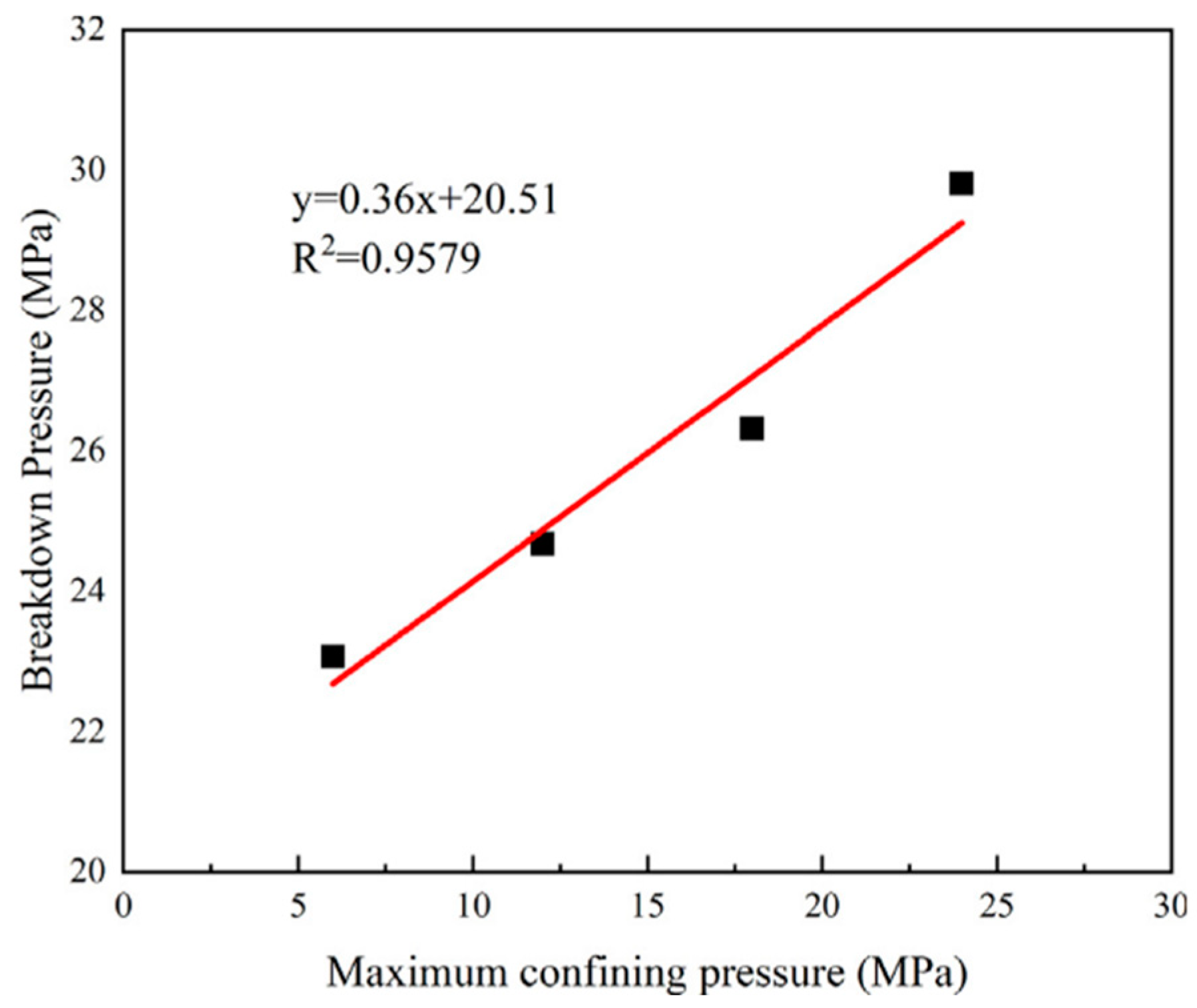
The propagation of hydraulic fractures decreases as confining pressure increases. The primary fracture tends to align with the principal stress direction [125]. Under low confining pressure, multiple vertical fractures typically form along the axial stress direction during failure [153]. As confining pressure increases, the fracture propagation shifts from vertical to oblique. The flow characteristics of fractures vary significantly between high-stress and low-stress states [44]. Figure 21 illustrates how breakdown pressure changes with different confining pressures, showing a nearly linear increase in breakdown pressure as confining pressure rises [67]. At higher confining pressures, flow pressure has a minimal effect on the fracture aperture; whereas, at lower confining pressures, flow pressure significantly alters the fracture aperture, thereby changing the flow dynamics of the fracture. Lower confining pressures can also result in secondary fractures along the direction of maximum principal stress, enlarging the stimulated area during hydraulic fracturing [64].
The path of hydraulic fracture propagation is primarily controlled by ground stress [46]. When the stress difference is large, simpler linear fractures tend to form. By contrast, smaller stress differences lead to more dispersed and complex fracture networks. Ground stress not only governs the propagation of fracture height but influences the complexity of fractures. Rock toughness plays a secondary role in restricting fracture propagation [154].

6. Conclusions

Hydraulic fracturing has proven to be a critical technique for enhancing geothermal energy extraction, especially in enhanced geothermal systems and Hot Dry Rock reservoirs. Through laboratory experiments and numerical simulations, researchers have uncovered various factors, such as rock properties, temperature, fluid injection rates, and stress conditions, influencing fracture initiation, propagation, and the overall efficiency of hydraulic fracturing. Key findings include the following:
(1)
Influence of experimental conditions: Fracturing outcomes are influenced by sample size, natural fracture distribution, joint characteristics, temperature, and fracturing fluid properties. Different experimental geometries, such as cylindrical or cubic blocks, simulate distinct stress conditions. High temperature induces thermal stress in the rock matrix, causing cracking and damage. As injection pressure increases, cracks connect to form a fracture network. Injection rates play a critical role in fracture propagation, with higher rates promoting lateral fracture propagation, while lower rates may fail to sustain hydraulic fracture growth.
(2)
Hydraulic fracture modeling: Classical models like the PKN and the KGD are limited to planar fracture propagation. By contrast, numerical models better capture complex fracture growth, especially in naturally fractured reservoirs. The finite element method offers a detailed fluid–structure coupling but has high computational costs. The discrete element method simulates fluid–rock interactions but cannot represent fracture networks. The finite–discrete element method is well-suited for modeling complex hydraulic fractures in reservoirs but remains computationally intensive.
(3)
Rock properties and fracture formation: Variations in the mineral composition and fracture toughness of rocks impact fracture behavior. High rock elasticity and temperature contribute to more complex fracture networks, while high initial rock temperatures facilitate thermal stress-induced fractures. The greater the fracture toughness of the rock matrix, the faster the formation of hydraulic fracture.
(4)
Fracture network complexity: Natural fractures significantly alter hydraulic fracture propagation, leading to more complex fracture systems, but also causing fluid leakage and energy dissipation. Fracture network complexity is influenced by stress conditions, rock temperature, and fluid injection rates. Four interaction modes between hydraulic and natural fractures have been identified: (a) crossover, (b) opening, (c) combined opening, and (d) opening crossover.
(5)
Proppant and fluid dynamics: Proppant use ensures fractures remain open after pumping pressure is reduced, affecting fracture shape and conductivity. Low injection rates hinder fracture propagation, while high injection rates enhance fracture width and area but can induce fluid-cooling effects.
(6)
Stress conditions: Horizontal and vertical stress differences dictate the propagation direction and complexity of hydraulic fractures. Under low confining pressure, more vertical fractures form, while higher confining pressure results in fewer, simpler fractures. The smaller the horizontal stress difference, the larger the deflection in the propagation direction of hydraulic fracture.
Rock temperature significantly influences the initiation location of hydraulic fractures. Additionally, the size of the rock introduces end effects that impact fracture propagation. However, conducting experiments under ultra-high temperatures and in situ stress conditions and using large-scale samples remain challenging due to technical limitations. Future research should focus on overcoming these obstacles to better simulate real-world conditions.

7. Recommendations for Future Work

(1)
Ultra-high temperature experiments: Most studies have been limited to temperatures up to 200 °C [216]. There is a need for research on hydraulic fracturing under ultra-high temperature conditions, particularly near the supercritical temperature of water, where complex “cloud fracture networks” form. Investigating whether this phenomenon is driven by thermal or fluid viscosity changes could provide valuable insights. Develop materials like polyether ether ketone (PEEK), with a melting point of 343 °C, and customize fluorine rubber for high-temperature wellbore sealing. These materials can simulate borehole conditions more effectively.
(2)
Large-scale experiments: Future studies should explore larger rock samples to minimize boundary effects and better simulate real-world conditions. Enhancing the load capacity and high-temperature resistance of triaxial testing devices will allow for more accurate replication of field stress and temperature conditions. Utilize advanced triaxial testing systems, such as the YJW-20000S [217], which can accommodate samples larger than 1000 mm, to minimize boundary effects and replicate field conditions more accurately.
(3)
New fracturing techniques: To improve fracture network complexity, especially in HDR with limited natural fractures, new methods such as cyclic hydraulic fracturing and temporary plug fracturing should be explored. Cyclic hydraulic fracturing has shown the potential to create more complex fracture systems by reducing the plastic deformation effect with each cycle. Compared with conventional hydraulic fracturing, cyclic injection hydraulic fracturing can significantly increase fracture permeability under the same confining pressure, and cyclic hydraulic fracturing can produce more complex fracture networks and reduce the possibility of induced earthquakes.
(4)
Stress condition studies: Further research is needed on the impact of varying vertical and horizontal stress differences on fracture network formation. This includes understanding how these stresses influence fracture propagation direction and the development of complex fracture networks, especially under high-stress environments. To conduct hydraulic fracturing experiments under in situ stress conditions, true triaxial stress loading and permeability testing systems could provide potential applications [218].
(5)
Improving rock and fracture property assessment: Evaluating the physical and mechanical properties of rocks remains a challenge in hydraulic fracturing. Improved characterization techniques are needed to better predict fracture behavior in both intact and fractured reservoirs, ultimately optimizing fracturing strategies for complex geological formations. Some advanced techniques such as CT can be applied to obtain the internal structures of rocks and observe the direction of fracture expansion [219].

Author Contributions

Writing—original draft preparation, Z.X.; conceptualization, project administration, and methodology, D.H. and K.L.; writing—review and editing, D.H. and K.L.; supervision, D.H. and J.L.; funding acquisition, D.H., K.L. and J.L. All authors have read and agreed to the published version of the manuscript.

Funding

This research was funded by the National Natural Science Foundation of China (Grant Nos. 52204118, 52204119, 52474119, 52474164) and the Natural Science Foundation of Hunan Province (Grant No. 2023JJ40729).

Conflicts of Interest

The authors declare that they have no conflicts of interest.

Nomenclature

Across-sectional area of fracture E Young’s modulus
C elasticity tensor · σ stress tensor
Ddiameter of cylindrical specimen ρ product of rock density
E plane strain modulus t time
Hheight of specimen g gravitational acceleration
σ1vertical stresspfluid pressure,
σ2maximum horizontal stressqflow rate
σ3minimum horizontal stress h fracture height
μviscosity of the fracturing fluidslocal coordinate along the fracture
q L leak-off flow rate w fracture width
p w f bottom hole pressure w ^ maximum aperture
L f fracture length at the center K I Mode I stress intensity factor
w a v g average fracture width P n internal fluid pressure
R maximum radius radial fracture

References

  1. Jia, Y.; Tsang, C.F.; Hammar, A.; Niemi, A. Hydraulic stimulation strategies in enhanced geothermal systems (EGS): A review. Geomech. Geophys. Geo-Energy Geo-Resour. 2022, 8, 211. [Google Scholar] [CrossRef]
  2. Allahvirdizadeh, P. A review on geothermal wells: Well integrity issues. J. Clean. Prod. 2020, 275, 124009. [Google Scholar] [CrossRef]
  3. Sircar, A.; Solanki, K.; Bist, N.; Yadav, K. Enhanced geothermal systems—Promises and challenges. Int. J. Renew. Energy Dev. 2022, 11, 333–346. [Google Scholar] [CrossRef]
  4. Hamm, S.G.; Anderson, A.; Blankenship, D.; Boyd, L.W.; Brown, E.A.; Frone, Z.; Hamos, I.; Hughes, H.J.; Kalmuk, M. Geothermal energy R&D: An overview of the U.S. department of energy’s geothermal technologies office. J. Energy Resour. Technol. Trans. ASME 2021, 143, 1–34. [Google Scholar]
  5. Zhuang, L.; Zang, A. Laboratory hydraulic fracturing experiments on crystalline rock for geothermal purposes. Earth-Sci. Rev. 2021, 216, 103580. [Google Scholar] [CrossRef]
  6. Zhu, Z.; Yang, S.; Ranjith, P.G.; Tian, W.; Tian, H.; Zheng, J.; Jiang, G.; Dou, B. A comprehensive review on mechanical responses of granite in enhanced geothermal systems (EGSs). J. Clean. Prod. 2023, 383, 135378. [Google Scholar] [CrossRef]
  7. Liu, Y.; Wang, G.; Zhu, X.; Li, T. Occurrence of geothermal resources and prospects for exploration and development in China. Energy Explor. Exploit. 2021, 39, 536–552. [Google Scholar] [CrossRef]
  8. Acar, H.I. A review of geothermal energy in Turkey. Energy Sources 2003, 25, 1083–1088. [Google Scholar] [CrossRef]
  9. Tomac, I.; Sauter, M. A review on challenges in the assessment of geomechanical rock performance for deep geothermal reservoir development. Renew. Sustain. Energy Rev. 2018, 82, 3972–3980. [Google Scholar] [CrossRef]
  10. Luo, J.; Zhu, Y.; Guo, Q.; Tan, L.; Zhuang, Y.; Liu, M.; Zhang, C.; Zhu, M.; Xiang, W. Chemical stimulation on the hydraulic properties of artificially fractured granite for enhanced geothermal system. Energy 2018, 142, 754–764. [Google Scholar] [CrossRef]
  11. Moska, R.; Labus, K.; Kasza, P. Hydraulic fracturing in enhanced geothermal systems—Field, tectonic and rock mechanics conditions—A review. Energies 2021, 14, 5725. [Google Scholar] [CrossRef]
  12. Kim, K.I.L.; Min, K.B.; Kim, K.Y.; Choi, J.W.; Yoon, K.S.; Yoon, W.S.; Yoon, B.; Lee, T.J.; Song, Y. Protocol for induced microseismicity in the first enhanced geothermal systems project in Pohang, Korea. Renew. Sustain. Energy Rev. 2018, 91, 1182–1191. [Google Scholar] [CrossRef]
  13. Alcolea, A.; Meier, P.; Vilarrasa, V.; Olivella, S.; Carrera, J. Hydromechanical modeling of the hydraulic stimulations in borehole PX2 (Pohang, South Korea). Geothermics 2024, 120, 103009. [Google Scholar] [CrossRef]
  14. Song, G.; Song, X.; Gensheng, L.I.; Ruina, X.U.; Cao, W.; Zhao, C. Multi-objective optimization of geothermal extraction from the enhanced geothermal system in Qiabuqia geothermal field, Gonghe basin. Acta Geol. Sin. 2021, 95, 1844–1856. [Google Scholar] [CrossRef]
  15. Yue, G.; Li, X.; Zhang, W. Risk assessment of earthquakes induced during HDR development: A case study in the Gonghe Basin, Qinghai Province, China. Geothermics 2023, 111, 102721. [Google Scholar] [CrossRef]
  16. Fang, Y.; den Hartog, S.A.M.; Elsworth, D.; Marone, C.; Cladouhos, T. Anomalous distribution of microearthquakes in the Newberry Geothermal Reservoir: Mechanisms and implications. Geothermics 2016, 63, 62–73. [Google Scholar] [CrossRef]
  17. Rutqvist, J.; Dobson, P.F.; Garcia, J.; Hartline, C.; Jeanne, P.; Oldenburg, C.M.; Vasco, D.W.; Walters, M. The Northwest Geysers EGS demonstration project, California: Pre-stimulation modeling and interpretation of the stimulation. Math. Geosci. 2015, 47, 3–29. [Google Scholar] [CrossRef]
  18. Feng, H.; Wang, E.; Zhao, A.; Wei, H.; Liu, Y.; Lu, J. Study on the law of true triaxial hydraulic fracturing by acoustic emission monitoring. ACS Omega 2024, 9, 24624–24632. [Google Scholar]
  19. Chen, Y.; Meng, Q.; Zhang, J. Effects of the notch angle, notch length and injection rate on hydraulic fracturing under true triaxial stress: An experimental study. Water 2018, 10, 801. [Google Scholar] [CrossRef]
  20. Hu, Y.; Su, B.; Mao, G. An experimental approach for determining unsaturated hydraulic properties of rock fractures. Nord. Hydrol. 2004, 35, 251–260. [Google Scholar]
  21. Zhuang, L.; Zang, A.; Jung, S. Grain-scale analysis of fracture paths from high-cycle hydraulic fatigue experiments in granites and sandstone. Int. J. Rock Mech. Min. Sci. 2022, 157, 105177. [Google Scholar] [CrossRef]
  22. Kusmierczyk, P.; Mishuris, G.; Wrobel, M. Remarks on application of different variables for the PKN model of hydrofracturing: Various fluid-flow regimes. Int. J. Fract. 2013, 184, 185–213. [Google Scholar] [CrossRef]
  23. Garikapati, H.; Verhoosel, C.V.; van Brummelen, E.H.; Zlotnik, S.; Díez, P. Sampling-based stochastic analysis of the PKN model for hydraulic fracturing. Comput. Geosci. 2019, 23, 81–105. [Google Scholar] [CrossRef]
  24. Peck, D.; Wrobel, M.; Perkowska, M.; Mishuris, G. Fluid velocity based simulation of hydraulic fracture: A penny shaped model—Part I: The numerical algorithm. Meccanica 2018, 53, 3615–3635. [Google Scholar] [CrossRef]
  25. Esfandiari, M.; Pak, A. XFEM modeling of the effect of in-situ stresses on hydraulic fracture characteristics and comparison with KGD and PKN models. J. Pet. Explor. Prod. Technol. 2023, 13, 185–201. [Google Scholar] [CrossRef]
  26. Zhang, B.; Guo, T.; Qu, Z.; Wang, J.; Chen, M.; Liu, X. Numerical simulation of fracture propagation and production performance in a fractured geothermal reservoir using a 2D FEM-based THMD coupling model. Energy 2023, 273, 127175. [Google Scholar] [CrossRef]
  27. Li, M.; Guo, P.; Stolle, D.F.E.; Liang, L.; Shi, Y. Modeling hydraulic fracture in heterogeneous rock materials using permeability-based hydraulic fracture model. Undergr. Space 2020, 5, 167–183. [Google Scholar] [CrossRef]
  28. Qian, Y.; Guo, P.; Wang, Y.; Zhao, Y.; Lin, H.; Liu, Y. Advances in laboratory-scale hydraulic fracturing experiments. Adv. Civ. Eng. 2020, 2020, 1386581. [Google Scholar] [CrossRef]
  29. Fu, H.; Huang, L.; Hou, B.; Weng, D.; Guan, B.; Zhong, T.; Zhao, Y. Experimental and numerical investigation on interaction mechanism between hydraulic fracture and natural fracture. Rock Mech. Rock Eng. 2024, 57, 10571–10582. [Google Scholar] [CrossRef]
  30. He, Y.; Bai, B.; Li, X. Investigation on heat transfer properties of supercritical water in a rock fracture for enhanced geothermal systems. Int. J. Thermophys. 2018, 39, 136. [Google Scholar] [CrossRef]
  31. Zhang, Y.; Ma, Y.; Hu, Z.; Lei, H.; Bai, L.; Lei, Z.; Zhang, Q. An experimental investigation into the characteristics of hydraulic fracturing and fracture permeability after hydraulic fracturing in granite. Renew. Energy 2019, 140, 615–624. [Google Scholar] [CrossRef]
  32. Zeng, Y.; Cheng, W.; Zhang, X.; Xiao, B. A criterion for identifying a mixed-mode I/II hydraulic fracture crossing a natural fracture in the subsurface. Energy Explor. Exploit. 2020, 38, 2507–2520. [Google Scholar] [CrossRef]
  33. Huang, Y.; Zhang, Y.; Yu, Z.; Ma, Y.; Zhang, C. Experimental investigation of seepage and heat transfer in rough fractures for enhanced geothermal systems. Renew. Energy 2019, 135, 846–855. [Google Scholar] [CrossRef]
  34. Hyman, J.D.; Jiménez-Martínez, J.; Viswanathan, H.S.; Carey, J.W.; Porter, M.L.; Rougier, E.; Karra, S.; Kang, Q.; Frash, L.; Chen, L.; et al. Understanding hydraulic fracturing: A multi-scale problem. Philos. Trans. R. Soc. A Math. Phys. Eng. Sci. 2016, 374, 20150426. [Google Scholar] [CrossRef]
  35. El-MShokir, E.M.; Al-Quraishi, A.A. Experimental and numerical investigation of proppant placement in hydraulic fractures. Pet. Sci. Technol. 2009, 27, 1690–1703. [Google Scholar] [CrossRef]
  36. Novikova, E.V.; Trimonova, M.A.; Turuntaev, S.B.; Zenchenko, E.V.; Zenchenko, P.E. Backstress Influence on the Formation Stress Field in Hydraulic Fracturing Experiments. Geosciences 2023, 13, 153. [Google Scholar] [CrossRef]
  37. Yan, T.; Li, W.; Bi, X. An experimental study of fracture initiation mechanisms during hydraulic fracturing. Pet. Sci. 2011, 8, 87–92. [Google Scholar] [CrossRef]
  38. Hou, B.; Chen, M.; Li, Z.; Wang, Y.; Diao, C. Propagation area evaluation of hydraulic fracture networks in shale gas reservoirs. Pet. Explor. Dev. 2014, 41, 833–838. [Google Scholar] [CrossRef]
  39. Jiang, Z.; Li, Q.; Hu, Q.; Liang, Y.; Xu, Y.; Liu, L.; Wu, X.; Li, X.; Wang, X.; Hu, L.; et al. Acoustic emission characteristics in hydraulic fracturing of stratified rocks: A laboratory study. Powder Technol. 2020, 371, 267–276. [Google Scholar] [CrossRef]
  40. Tan, P.; Chen, Z.; Fu, S.; Zhao, Q. Experimental investigation on fracture growth for integrated hydraulic fracturing in multiple gas bearing formations. Geoenergy Sci. Eng. 2023, 231, 212316. [Google Scholar] [CrossRef]
  41. Hadei, M.R.; Veiskarami, A. An experimental investigation of hydraulic fracturing of stratified rocks. Bull. Eng. Geol. Environ. 2021, 80, 491–506. [Google Scholar] [CrossRef]
  42. Zhuang, D.; Yin, T.; Li, Q.; Wu, Y.; Tan, X. Effect of injection flow rate on fracture toughness during hydraulic fracturing of hot dry rock (HDR). Eng. Fract. Mech. 2022, 260, 108207. [Google Scholar] [CrossRef]
  43. Wang, D.; Zhou, F.; Dong, Y.; Sun, D.; Yu, B. Experimental investigation of thermal effect on fracability index of geothermal reservoirs. Nat. Resour. Res. 2021, 30, 273–288. [Google Scholar] [CrossRef]
  44. Ma, Y.; Zhang, Y.; Huang, Y.; Zhang, Y.; Hu, Z. Experimental study on flow and heat transfer characteristics of water flowing through a rock fracture induced by hydraulic fracturing for an enhanced geothermal system. Appl. Therm. Eng. 2019, 154, 433–441. [Google Scholar] [CrossRef]
  45. Luo, Y.; Xu, W.; Lei, Y.; Wu, P.; Qin, G.; Ba, R. Experimental study of heat transfer by water flowing through smooth and rough rock fractures. Energy Rep. 2019, 5, 1025–1029. [Google Scholar] [CrossRef]
  46. Tan, P.; Pang, H.; Jin, Y.; Zhou, Z. Experiments and analysis of hydraulic fracturing in hot dry rock geothermal reservoirs using an improved large-size high-temperature true triaxial apparatus. Nat. Gas. Ind. B. 2024, 11, 83–94. [Google Scholar] [CrossRef]
  47. Goto, R.; Watanabe, N.; Sakaguchi, K.; Miura, T.; Chen, Y.; Ishibashi, T.; Pramudyo, E.; Parisio, F.; Yoshioka, K.; Nakamura, K.; et al. Creating cloud-fracture network by flow-induced microfracturing in superhot geothermal environments. Rock Mech. Rock Eng. 2021, 54, 2959–2974. [Google Scholar] [CrossRef]
  48. Xing, Y.; Zhang, G.; Luo, T.; Jiang, Y.; Ning, S. Hydraulic fracturing in high-temperature granite characterized by acoustic emission. J. Pet. Sci. Eng. 2019, 178, 475–484. [Google Scholar] [CrossRef]
  49. Guo, L.; Wang, Z.; Zhang, Y.; Wang, Z.; Jiang, H. Experimental and numerical evaluation of hydraulic fracturing under high temperature and embedded fractures in large concrete samples. Water 2020, 12, 3171. [Google Scholar] [CrossRef]
  50. Wang, D.; Bian, X.; Qin, H.; Sun, D.; Yu, B. Experimental investigation of mechanical properties and failure behavior of fluid-saturated hot dry rocks. Nat. Resour. Res. 2021, 30, 289–305. [Google Scholar] [CrossRef]
  51. Zenchenko, E.V.; Turuntaev, S.B.; Nachev, V.A.; Chumakov, T.K.; Zenchenko, P.E. Study of the interaction of a hydraulic fracture with a natural fracture in a laboratory experiment based on ultrasonic transmission monitoring. Energies 2024, 17, 277. [Google Scholar] [CrossRef]
  52. Goodfellow, S.D.; Nasseri, M.H.B.; Maxwell, S.C.; Young, R.P. Hydraulic fracture energy budget: Insights from the laboratory. Geophys. Res. Lett. 2015, 42, 3179–3187. [Google Scholar] [CrossRef]
  53. Sawayama, K.; Ishibashi, T.; Jiang, F.; Tsuji, T.; Nishizawa, O.; Fujimitsu, Y. Scale-independent relationship between permeability and resistivity in mated fractures with natural rough surfaces. Geothermics 2021, 94, 102065. [Google Scholar] [CrossRef]
  54. Qin, Q.; Xue, Q.; Ma, Z.; Zheng, Y.; Zhai, H. Hydraulic fracturing simulations with real-time evolution of physical parameters. Energies 2021, 14, 1678. [Google Scholar] [CrossRef]
  55. Rodríguez Villarreal, O.; Varela Valdez, A.; La Borderie, C.; Pijaudier-Cabot, G.; Hinojosa Rivera, M. Estimation of Fracture Energy from Hydraulic Fracture Tests on Mortar and Rocks at Geothermal Reservoir Temperatures. Rock Mech. Rock Eng. 2021, 54, 4111–4119. [Google Scholar] [CrossRef]
  56. Zhang, P.; Zhang, Y.; Huang, Y.; Xia, Y. Experimental study of fracture evolution in enhanced geothermal systems based on fractal theory. Geothermics 2022, 102, 102406. [Google Scholar] [CrossRef]
  57. Cheng, W.; Jin, Y.; Chen, M. Reactivation mechanism of natural fractures by hydraulic fracturing in naturally fractured shale reservoirs. J. Nat. Gas. Sci. Eng. 2015, 27, 1357–1365. [Google Scholar] [CrossRef]
  58. Deng, J.Q.; Lin, C.; Yang, Q.; Liu, Y.R.; Tao, Z.F.; Duan, H.F. Investigation of directional hydraulic fracturing based on true tri-axial experiment and finite element modeling. Comput. Geotech. 2016, 75, 28–47. [Google Scholar] [CrossRef]
  59. Liu, B.; Jin, Y.; Chen, M. Influence of vugs in fractured-vuggy carbonate reservoirs on hydraulic fracture propagation based on laboratory experiments. J. Struct. Geol. 2019, 124, 143–150. [Google Scholar] [CrossRef]
  60. Hu, L.; Ghassemi, A. Heat production from lab-scale enhanced geothermal systems in granite and gabbro. Int. J. Rock Mech. Min. Sci. 2020, 126, 104205. [Google Scholar] [CrossRef]
  61. Dehghan, A.N. An experimental investigation into the influence of pre-existing natural fracture on the behavior and length of propagating hydraulic fracture. Eng. Fract. Mech. 2020, 240, 107330. [Google Scholar] [CrossRef]
  62. Liu, Y.; Xu, T.; Yuan, Y.; Feng, B.; Tang, X.; Liu, X.; Cui, Z. A laboratory study on fracture initiation and propagation of granite under cyclic-injection hydraulic fracturing. J. Pet. Sci. Eng. 2022, 212, 110278. [Google Scholar] [CrossRef]
  63. Zhu, Y.; Liu, C.; Zhang, H.; Wang, B.; Mao, M.; Geng, H.; Zhao, C. Micro mechanism investigation of hydraulic fracturing process based a fluid-solid coupling discrete element model. Comput. Geotech. 2024, 174, 106640. [Google Scholar] [CrossRef]
  64. Yin, W.; Feng, Z.; Zhao, Y. Investigation on the characteristics of hydraulic fracturing in fractured-subsequently-filled hot dry rock geothermal formation. Renew. Energy 2024, 223, 120061. [Google Scholar] [CrossRef]
  65. Huang, B.; Li, P.; Ma, J.; Chen, S. Experimental investigation on the basic law of hydraulic fracturing after water pressure control blasting. Rock Mech. Rock Eng. 2014, 47, 1321–1334. [Google Scholar] [CrossRef]
  66. Yu, J.; Li, N.; Hui, B.; Zhao, W.; Li, Y.; Kang, J.; Hu, P.; Chen, Y. Experimental simulation of fracture propagation and extension in hydraulic fracturing: A state-of-the-art review. Fuel 2024, 363, 131021. [Google Scholar] [CrossRef]
  67. Cheng, Y.; Zhang, Y.; Yu, Z.; Hu, Z.; Yang, Y. An investigation on hydraulic fracturing characteristics in granite geothermal reservoir. Eng. Fract. Mech. 2020, 237, 107252. [Google Scholar] [CrossRef]
  68. Li, N.; Xie, H.; Hu, J.; Li, C. A critical review of the experimental and theoretical research on cyclic hydraulic fracturing for geothermal reservoir stimulation. Geomech. Geophys. Geo-Energy Geo-Resour. 2022, 8, 7. [Google Scholar] [CrossRef]
  69. Zhong, C.; Xu, T.; Yuan, Y.; Cui, G.; Gherardi, F.; Li, X. Coupled effects of elastic and plastic deformation on hydraulic properties of the geothermal fracture induced by cyclic loading-unloading processes. Eng. Geol. 2023, 313, 106929. [Google Scholar] [CrossRef]
  70. Kc, B.; Ghazanfari, E.; McLennan, J.; Frash, L.P.; Meng, M. Evaluation of sintered bauxite proppant for binary enhanced geothermal systems. Geomech. Geophys. Geo-Energy Geo-Resour. 2024, 10, 21. [Google Scholar] [CrossRef]
  71. Wu, X.; Guo, Y.; Chang, X.; Bi, Z.; Zhao, G.; Yang, H.; Guo, W. Experimental study on cyclic hydraulic fracturing of tight sandstone under In-Situ stress. Processes 2023, 11, 875. [Google Scholar] [CrossRef]
  72. Feng, G.; Wang, X.; Kang, Y.; Zhang, Z. Effect of thermal cycling-dependent cracks on physical and mechanical properties of granite for enhanced geothermal system. Int. J. Rock Mech. Min. Sci. 2020, 134, 104476. [Google Scholar] [CrossRef]
  73. Adachi, J.; Siebrits, E.; Peirce, A.; Desroches, J. Computer simulation of hydraulic fractures. Int. J. Rock Mech. Min. Sci. 2007, 44, 739–757. [Google Scholar] [CrossRef]
  74. Chen, B.; Barboza1, B.R.; Sun, Y.; Bai, J.; Thomas1, H.R.; Dutko, M.; Cottrel, M.; Li, C. A Review of Hydraulic Fracturing Simulation. Arch. Comput. Methods Eng. 2022, 29, 1–58. [Google Scholar] [CrossRef]
  75. Ismail, A.; Azadbakht, S. A comprehensive review of numerical simulation methods for hydraulic fracturing. Int. J. Numer. Anal. Methods Geomech. 2024, 48, 1433–1459. [Google Scholar] [CrossRef]
  76. Aliyu, M.D.; Chen, H.P. Enhanced geothermal system modelling with multiple pore media: Thermo-hydraulic coupled processes. Energy 2018, 165, 931–948. [Google Scholar] [CrossRef]
  77. Nguyen, H.T.; Lee, J.H.; Elraies, K.A. A review of PKN-type modeling of hydraulic fractures. J. Pet. Sci. Eng. 2020, 195, 107607. [Google Scholar] [CrossRef]
  78. Dalla Barba, F.; Picano, F. A novel approach for direct numerical simulation of hydraulic fracture problems. Flow Turbul. Combust. 2020, 105, 335–357. [Google Scholar] [CrossRef]
  79. Nguyen, H.T.; Lee, J.H.; Elraies, K.A. Pseudo-three-dimensional simulations of a vertical hydraulic fracture with time-dependent injection rates. Pet. Sci. Technol. 2022, 40, 1349–1368. [Google Scholar] [CrossRef]
  80. Sarris, E.; Papanastasiou, P. The influence of the cohesive process zone in hydraulic fracturing modelling. Int. J. Fract. 2011, 167, 33–45. [Google Scholar] [CrossRef]
  81. Meng, Q.; Xue, H.; Zhuang, X.; Zhang, Q.; Zhu, C.; He, B.; Feng, G.; Rabczuk, T. An IFS-based fractal discrete fracture network for hydraulic fracture behavior of rock mass. Eng. Geol. 2023, 324, 107247. [Google Scholar] [CrossRef]
  82. Perkins, T.K.; Kern, L.R. Widths of hydraulic fractures. J. Pet. Technol. 1961, 13, 937–949. [Google Scholar] [CrossRef]
  83. Nordgren, R.P. Propagation of a vertical hydraulic fracture. Soc. Pet. Eng. J. 1972, 12, 306–314. [Google Scholar] [CrossRef]
  84. Geertsma, J.; De Klerk, F. A rapid method of predicting width and extent of hydraulically induced fractures. J. Pet. Technol. 1969, 21, 1571–1581. [Google Scholar] [CrossRef]
  85. Khristianovich, S.; Zheltov, Y. Formation of vertical fractures by means of highly viscous liquid. World Pet. Congr. 2015, 141, 226–235. [Google Scholar]
  86. Detournay, E.; Hakobyan, Y. Hydraulic fracturing of weak rock during waterflooding. Int. J. Numer. Anal. Methods Geomech. 2022, 46, 416–435. [Google Scholar] [CrossRef]
  87. Wrobel, M.; Papanastasiou, P.; Peck, D. A simplified modelling of hydraulic fractures in elasto-plastic materials. Int. J. Fract. 2022, 233, 153–178. [Google Scholar] [CrossRef]
  88. Carbonell, R.; Desroches, J.; Detournay, E. A comparison between a semi-analytical and a numerical solution of a two-dimensional hydraulic fracture. Int. J. Solids Struct. 1999, 36, 4869–4888. [Google Scholar] [CrossRef]
  89. Dontsov, E.V.; Peirce, A.P. Proppant transport in hydraulic fracturing: Crack tip screen-out in KGD and P3D models. Int. J. Solids Struct. 2015, 63, 206–218. [Google Scholar] [CrossRef]
  90. Jin, T. A consistent linearization scheme for KGD problems using fracture tip asymptotic solutions. Int. J. Numer. Anal. Methods Geomech. 2023, 47, 2899–2924. [Google Scholar] [CrossRef]
  91. Jin, J.; Wang, X.; Liu, X.; Xu, Y.; Lu, D. A novel hydraulic fracturing model for the fluid-driven fracture propagation in poroelastic media containing the natural cave. Phys. Fluids 2023, 35, 096602. [Google Scholar] [CrossRef]
  92. Gee, B.; Gracie, R. Inertial and turbulent flow in hydro-mechanically coupled KGD-like fractures. Int. J. Numer. Anal. Methods Geomech. 2023, 47, 2925–2950. [Google Scholar] [CrossRef]
  93. Green, A.E.; Sneddon, I.N. The distribution of stress in the neighbourhood of a flat elliptical crack in an elastic solid. Math. Proc. Camb. Philos. Soc. 1950, 46, 159–163. [Google Scholar] [CrossRef]
  94. Savitski, A.; Detournay, E. Propagation of a penny-shape hydraulic fracture in an impermeable rock. In Proceedings of the Vail Rocks 1999—37th US Symposium on Rock Mechanics (USRMS), Vail, Colorado, 7–9 June 1999; Volume 39, pp. 851–858. [Google Scholar]
  95. Mašín, D.; Tamagnini, C.; Viggiani, G.; Costanzo, D. Directional response of a reconstituted fine-grained soil—Part II: Performance of different constitutive models. Int. J. Numer. Anal. Methods Geomech. 2006, 30, 1303–1336. [Google Scholar] [CrossRef]
  96. Zolfaghari, N.; Dontsov, E.; Bunger, A.P. Solution for a plane strain rough-walled hydraulic fracture driven by turbulent fluid through impermeable rock. Int. J. Numer. Anal. Methods Geomech. 2018, 42, 587–617. [Google Scholar] [CrossRef]
  97. Linkov, A.M.; Markov, N.S. Improved pseudo three-dimensional model for hydraulic fractures under stress contrast. Int. J. Rock Mech. Min. Sci. 2020, 130, 104316. [Google Scholar] [CrossRef]
  98. Adachi, J.I.; Detournay, E.; Peirce, A.P. Analysis of the classical pseudo-3D model for hydraulic fracture with equilibrium height growth across stress barriers. Int. J. Rock Mech. Min. Sci. 2010, 47, 625–639. [Google Scholar] [CrossRef]
  99. Simonson, E.R.; Abou-Sayed, A.S.; Clifton, R.J. Containment of massive hydraulic fractures. Soc. Pet. Eng. J. 1978, 18, 27–32. [Google Scholar] [CrossRef]
  100. Fomin, S.; Hashida, T.; Shimizu, A.; Matsuki, K.; Sakaguchi, K. Fractal concept in numerical simulation of hydraulic fracturing of the hot dry rock geothermal reservoir. Hydrol. Process. 2003, 17, 2975–2989. [Google Scholar] [CrossRef]
  101. Chen, M.; Guo, T.; Zou, Y.; Zhang, S.; Qu, Z. Numerical simulation of proppant transport coupled with Multi-Planar-3D hydraulic fracture propagation for Multi-Cluster fracturing. Rock Mech. Rock Eng. 2022, 55, 565–590. [Google Scholar] [CrossRef]
  102. Yan, C.; Zheng, H. Three-Dimensional hydromechanical model of hydraulic fracturing with arbitrarily discrete fracture networks using finite-discrete element method. Int. J. Geomech. 2017, 17, 6. [Google Scholar] [CrossRef]
  103. Qin, M.; Yang, D.; Chen, W. Three-dimensional hydraulic fracturing modeling based on peridynamics. Eng. Anal. Bound. Elem. 2022, 141, 153–166. [Google Scholar] [CrossRef]
  104. Zia, H.; Lecampion, B.; Zhang, W. Impact of the anisotropy of fracture toughness on the propagation of planar 3D hydraulic fracture. Int. J. Fract. 2018, 211, 103–123. [Google Scholar] [CrossRef]
  105. Li, F.; Xu, T.; Li, S.; Feng, B.; Jia, X.; Feng, G.; Zhu, H.; Jiang, Z. Assessment of energy production in the deep carbonate geothermal reservoir by wellbore-reservoir integrated fluid and heat transport modeling. Geofluids 2019, 2019, 8573182. [Google Scholar] [CrossRef]
  106. Salimzadeh, S.; Nick, H.M.; Zimmerman, R.W. Thermoporoelastic effects during heat extraction from low-permeability reservoirs. Energy 2018, 142, 546–558. [Google Scholar] [CrossRef]
  107. Liu, X.; Liu, Q.; Liu, B.; Kang, Y.; He, J. Numerical manifold method for thermal–hydraulic coupling in fractured enhance geothermal system. Eng. Anal. Bound. Elem. 2019, 101, 67–75. [Google Scholar] [CrossRef]
  108. Gao, X.; Li, T.; Zhang, Y.; Kong, X.; Meng, N. A review of simulation models of heat extraction for a geothermal reservoir in an enhanced geothermal system. Energies 2022, 15, 7148. [Google Scholar] [CrossRef]
  109. Rawal, C.; Ghassemi, A. A reactive thermo-poroelastic analysis of water injection into an enhanced geothermal reservoir. Geothermics 2014, 50, 10–23. [Google Scholar] [CrossRef]
  110. Bao, J.Q.; Fathi, E.; Ameri, S. A coupled finite element method for the numerical simulation of hydraulic fracturing with a condensation technique. Eng. Fract. Mech. 2014, 131, 269–281. [Google Scholar] [CrossRef]
  111. Shauer, N.; Duarte, C.A. Improved algorithms for generalized finite element simulations of three-dimensional hydraulic fracture propagation. Int. J. Numer. Anal. Methods Geomech. 2019, 43, 2707–2742. [Google Scholar] [CrossRef]
  112. Ma, G.; Wang, Y.; Li, T.; Chen, Y. A mesh mapping method for simulating stress-dependent permeability of three-dimensional discrete fracture networks in rocks. Comput. Geotech. 2019, 108, 95–106. [Google Scholar] [CrossRef]
  113. Chen, Y.; Wang, H.; Li, T.; Wang, Y.; Ren, F.; Ma, G. Evaluation of geothermal development considering proppant embedment in hydraulic fractures. Renew. Energy 2020, 153, 985–997. [Google Scholar] [CrossRef]
  114. Profit, M.; Dutko, M.; Yu, J.; Cole, S.; Angus, D.; Baird, A. Complementary hydro-mechanical coupled finite/discrete element and microseismic modelling to predict hydraulic fracture propagation in tight shale reservoirs. Comput. Part. Mech. 2016, 3, 229–248. [Google Scholar] [CrossRef]
  115. Zhang, F.; Damjanac, B.; Maxwell, S. Investigating hydraulic fracturing complexity in naturally fractured rock masses using fully coupled multiscale numerical modeling. Rock Mech. Rock Eng. 2019, 52, 5137–5160. [Google Scholar] [CrossRef]
  116. Cheng, Q.; Wang, X.; Ghassemi, A. Numerical simulation of reservoir stimulation with reference to the Newberry EGS. Geothermics 2019, 77, 327–343. [Google Scholar] [CrossRef]
  117. Zhao, Y.; Feng, Z.; Feng, Z.; Yang, D.; Liang, W. THM (Thermo-hydro-mechanical) coupled mathematical model of fractured media and numerical simulation of a 3D enhanced geothermal system at 573K and buried depth 6000–7000M. Energy 2015, 82, 193–205. [Google Scholar] [CrossRef]
  118. Bakhshi, E.; Golsanami, N.; Chen, L. Numerical modeling and lattice method for characterizing hydraulic fracture propagation: A review of the numerical, experimental, and field studies. Arch. Comput. Methods Eng. 2021, 28, 3329–3360. [Google Scholar] [CrossRef]
  119. Belytschko, T.; Black, T. Elastic crack growth in finite elements with minimal remeshing. Int. J. Numer. Methods Eng. 1999, 45, 601–620. [Google Scholar] [CrossRef]
  120. Maulianda, B.; Savitri, C.D.; Prakasan, A.; Atdayev, E.; Yan, T.W.; Yong, Y.K.; Elrais, K.A.; Barati, R. Recent comprehensive review for extended finite element method (XFEM) based on hydraulic fracturing models for unconventional hydrocarbon reservoirs. J. Pet. Explor. Prod. Technol. 2020, 10, 3319–3331. [Google Scholar] [CrossRef]
  121. Ren, Q.; Dong, Y.; Yu, T. Numerical modeling of concrete hydraulic fracturing with extended finite element method. Sci. China Ser. E Technol. Sci. 2009, 52, 559–565. [Google Scholar] [CrossRef]
  122. Zheng, A.X.; Luo, X.Q. Hydro-mechanical modeling of impermeable discontinuity in rock by extended finite element method. J. Cent. South Univ. 2015, 22, 4337–4346. [Google Scholar] [CrossRef]
  123. Zheng, A.; Luo, X. A mathematical programming approach for frictional contact problems with the extended finite element method. Arch. Appl. Mech. 2016, 86, 599–616. [Google Scholar] [CrossRef]
  124. Xu, D.D.; Liu, Z.L.; Zhuang, Z.; Zeng, Q.L.; Wang, T. Study on interaction between induced and natural fractures by extended finite element method. Sci. China Phys. Mech. Astron. 2017, 60, 024611. [Google Scholar] [CrossRef]
  125. Zhou, Z.; Mikada, H.; Takekawa, J.; Xu, S. Numerical simulation of hydraulic fracturing in enhanced geothermal systems considering thermal stress cracks. Pure Appl. Geophys. 2022, 179, 1775–1804. [Google Scholar] [CrossRef]
  126. Wang, Y.; Li, X.; Zhao, B.; Zhang, Z. Numerical simulation of particle plugging in hydraulic fracture by element partition method. Int. J. Numer. Anal. Methods Geomech. 2020, 44, 1857–1879. [Google Scholar] [CrossRef]
  127. Torres, S.A.G.; Castaño, J.D.M. Simulation of the hydraulic fracture process in two dimensions using a discrete element method. Phys. Rev. E—Stat. Nonlinear Soft Matter Phys. 2007, 75, 066109. [Google Scholar] [CrossRef]
  128. Leonardi, C.R.; McCullough, J.W.S.; Jones, B.D.; Williams, J.R. Electromagnetic excitation of particle suspensions in hydraulic fractures using a coupled lattice Boltzmann-discrete element model. Comput. Part. Mech. 2016, 3, 125–140. [Google Scholar] [CrossRef]
  129. Cao, M.; Sharma, M.M. Effect of fracture geometry, topology and connectivity on energy recovery from enhanced geothermal systems. Energy 2023, 282, 128368. [Google Scholar] [CrossRef]
  130. Yang, W.; Lv, X.; Wang, L.; Peng, D.; Chen, X. A DEM–CFD coupling method for modelling two-hole synchronous hydraulic fracturing. Geomech. Geophys. Geo-Energy Geo-Resour. 2023, 9, 6. [Google Scholar] [CrossRef]
  131. Yasin, Q.; Majdanski, M.; Awan, R.S.; Golsanami, N. An analytical hierarchy-based method for quantifying hydraulic fracturing stimulation to improve geothermal well productivity. Energies 2022, 15, 7368. [Google Scholar] [CrossRef]
  132. Ju, Y.; Chen, J.; Wang, Y.; Gao, F.; Xie, H. Numerical analysis of hydrofracturing behaviors and mechanisms of heterogeneous reservoir glutenite, Using the continuum-Based discrete element method while considering hydromechanical coupling and leak-Off effects. J. Geophys. Res. Solid Earth 2018, 123, 3621–3644. [Google Scholar] [CrossRef]
  133. Munjiza, A.; Andrews, K.R.F.; White, J.K. Combined single and smeared crack model in combined finite-discrete element analysis. Int. J. Numer. Methods Eng. 1999, 44, 41–57. [Google Scholar] [CrossRef]
  134. Qu, T.; Feng, Y.T.; Wang, M.; Jiang, S. Calibration of parallel bond parameters in bonded particle models via physics-informed adaptive moment optimisation. Powder Technol. 2020, 366, 527–536. [Google Scholar] [CrossRef]
  135. Munjiza, A.; Owen, D.R.J.; Bicanic, N. A combined finite-discrete element method in transient dynamics of fracturing solids. Eng. Comput. 1995, 12, 145–174. [Google Scholar] [CrossRef]
  136. Yan, C.; Zheng, H.; Sun, G.; Ge, X. Combined finite-discrete element method for simulation of hydraulic fracturing. Rock Mech. Rock Eng. 2016, 49, 1389–1410. [Google Scholar] [CrossRef]
  137. Zheng, H.; Pu, C.; Sun, C. Numerical investigation on the hydraulic fracture propagation based on combined finite-discrete element method. J. Struct. Geol. 2020, 130, 103926. [Google Scholar] [CrossRef]
  138. Wu, M.; Gao, K.; Liu, J.; Song, Z.; Huang, X. Influence of rock heterogeneity on hydraulic fracturing: A parametric study using the combined finite-discrete element method. Int. J. Solids Struct. 2022, 234–235, 111293. [Google Scholar] [CrossRef]
  139. Yan, C.; Xie, X.; Ren, Y.; Ke, W.; Wang, G. A FDEM-based 2D coupled thermal-hydro-mechanical model for multiphysical simulation of rock fracturing. Int. J. Rock Mech. Min. Sci. 2022, 149, 104964. [Google Scholar] [CrossRef]
  140. Lin, Y.; Wang, X.; Ma, J.; Huang, L. A finite-discrete element based appoach for modelling the hydraulic fracturing of rocks with irregular inclusions. Eng. Fract. Mech. 2022, 261, 108209. [Google Scholar] [CrossRef]
  141. Behnia, M.; Goshtasbi, K.; Marji, M.F.; Golshani, A. Numerical simulation of crack propagation in layered formations. Arab. J. Geosci. 2014, 7, 2729–2737. [Google Scholar] [CrossRef]
  142. Behnia, M.; Goshtasbi, K.; Marji, M.F.; Golshani, A. Numerical simulation of interaction between hydraulic and natural fractures in discontinuous media. Acta Geotech. 2015, 10, 533–546. [Google Scholar] [CrossRef]
  143. Shi, J.; Shen, B. A numerical study of effect of cold temperature on growth orientation of horizontal fractures using displacement discontinuity method. Geomech. Energy Environ. 2022, 31, 100319. [Google Scholar] [CrossRef]
  144. Zhou, X.X.; Ghassemi, A.; Cheng, A.H.-D. A three-dimensional integral equation model for calculating poro- and thermoelastic stresses induced by cold water injection into a geothermal reservoir. Int. J. Numer. Anal. Methods Geomech. 2009, 33, 1613–1640. [Google Scholar] [CrossRef]
  145. Ghassemi, A.; Zhou, X. A three-dimensional thermo-poroelastic model for fracture response to injection/extraction in enhanced geothermal systems. Geothermics 2011, 40, 39–49. [Google Scholar] [CrossRef]
  146. Xu, Y.; Li, X.; Liu, Q.; Yang, S.; Tan, X. A semi-analytical solution of finite-conductivity multi-wing fractured well in naturally fractured reservoirs by boundary element method. J. Pet. Sci. Eng. 2021, 203, 108584. [Google Scholar] [CrossRef]
  147. He, Y.; Yang, Z.; Li, X.; Song, R. Numerical simulation study on three-dimensional fracture propagation of synchronous fracturing. Energy Sci. Eng. 2020, 8, 944–958. [Google Scholar] [CrossRef]
  148. Kebir, H.; Roelandt, J.M.; Foulquier, J. A new singular boundary element for crack problems: Application to bolted joints. Eng. Fract. Mech. 1999, 62, 497–510. [Google Scholar] [CrossRef]
  149. Cheng, S.; Zhang, M.; Zhang, X.; Wu, B.; Chen, Z.; Lei, Z.; Tan, P. Numerical study of hydraulic fracturing near a wellbore using dual boundary element method. Int. J. Solids Struct. 2022, 239–240, 111479. [Google Scholar] [CrossRef]
  150. Ji, J.; Song, X.; Song, G.; Xu, F.; Shi, Y.; Lv, Z.; Li, S.; Yi, J. Study on fracture evolution model of the enhanced geothermal system under thermal-hydraulic-chemical-deformation coupling. Energy 2023, 269, 126604. [Google Scholar] [CrossRef]
  151. Zhang, W.; Qu, Z.; Guo, T.; Wang, Z. Study of the enhanced geothermal system (EGS) heat mining from variably fractured hot dry rock under thermal stress. Renew. Energy 2019, 143, 855–871. [Google Scholar] [CrossRef]
  152. Ma, W.; Wang, Y.; Wu, X.; Liu, G. Hot dry rock (HDR) hydraulic fracturing propagation and impact factors assessment via sensitivity indicator. Renew. Energy 2020, 146, 2716–2723. [Google Scholar] [CrossRef]
  153. Guo, L.L.; Zhang, Y.B.; Zhang, Y.J.; Yu, Z.W.; Zhang, J.N. Experimental investigation of granite properties under different temperatures and pressures and numerical analysis of damage effect in enhanced geothermal system. Renew. Energy 2018, 126, 107–125. [Google Scholar] [CrossRef]
  154. Li, Y.; Long, M.; Tang, J.; Chen, M.; Fu, X. A hydraulic fracture height mathematical model considering the influence of plastic region at fracture tip. Pet. Explor. Dev. 2020, 47, 184–195. [Google Scholar] [CrossRef]
  155. Yu, L.; Wu, X.; Wang, Y.; Ma, W.; Liu, G. Stratified rock hydraulic fracturing for enhanced geothermal system and fracture geometry evaluation via effective length. Renew. Energy 2020, 152, 713–723. [Google Scholar] [CrossRef]
  156. Guo, T.; Tang, S.; Liu, S.; Liu, X.; Zhang, W.; Qu, G. Numerical simulation of hydraulic fracturing of hot dry rock under thermal stress. Eng. Fract. Mech. 2020, 240, 107350. [Google Scholar] [CrossRef]
  157. Kolawole, O.; Ispas, I.; Kolawole, F.; Germay, C.; McLennan, J.D. Mechanical zonation of rock properties and the development of fluid migration pathways: Implications for enhanced geothermal systems in sedimentary-hosted geothermal reservoirs. Geotherm. Energy 2021, 9, 14. [Google Scholar] [CrossRef]
  158. Huang, W.; Cao, W.; Jiang, F. Heat extraction performance of EGS with heterogeneous reservoir: A numerical evaluation. Int. J. Heat. Mass. Transf. 2017, 108, 645–657. [Google Scholar] [CrossRef]
  159. Liu, J.; Xue, Y.; Peng, C.; Wang, H.; Liang, X.; Li, S.T. The role of spatially-autocorrelated heterogeneous and anisotropic fracture roughness on the thermal breakthrough of geothermal doublet systems. Geoenergy Sci. Eng. 2024, 237, 212801. [Google Scholar] [CrossRef]
  160. Liu, D.D.; Xiang, Y.Y.; Zheng, J.L. Integral equation solution for three-dimensional heat transfer in multiple-fracture enhanced geothermal reservoirs. Int. J. Numer. Anal. Methods Geomech. 2020, 44, 1511–1524. [Google Scholar] [CrossRef]
  161. Han, D.; Zhang, W.; Jiao, K.; Yu, B.; Li, T.; Gong, L.; Wang, S. Thermal−hydraulic−mechanical−chemical coupling analysis of enhanced geothermal systems based on an embedded discrete fracture model. Nat. Gas. Ind. B 2023, 10, 533–546. [Google Scholar] [CrossRef]
  162. Duan, X.Y.; Huang, D.; Lei, W.X.; Chen, S.C.; Huang, Z.Q.; Zhu, C.Y. Investigation of Heat Extraction in an Enhanced Geothermal System Embedded with Fracture Networks Using the Thermal–Hydraulic–Mechanical Coupling Model. Energies 2023, 16, 3758. [Google Scholar] [CrossRef]
  163. Yang, J.; Wang, J.; Hu, B. Numerical analysis of the impacts of multiscale fractures on geothermal reservoir capacity. J. Energy Eng. 2023, 149, 1–16. [Google Scholar] [CrossRef]
  164. Chen, Y.; Ma, G.; Wang, H.; Li, T. Evaluation of geothermal development in fractured hot dry rock based on three dimensional unified pipe-network method. Appl. Therm. Eng. 2018, 136, 219–228. [Google Scholar] [CrossRef]
  165. Yang, S.; Qin, F.; Hu, J.; Wang, H. Thermo-hydro-mechanical optimization of the enhanced geothermal system for commercial utilization. Appl. Therm. Eng. 2022, 213, 118641. [Google Scholar] [CrossRef]
  166. Zhang, X.; Wang, Z.; Sun, Y.; Zhu, C.; Xiong, F.; Tang, Q. Numerical simulation on heat transfer characteristics of water flowing through the fracture of high-temperature rock. Geofluids 2020, 2020, 8864028. [Google Scholar] [CrossRef]
  167. Slatlem Vik, H.; Salimzadeh, S.; Nick, H.M. Heat recovery from multiple-fracture enhanced geothermal systems: The effect of thermoelastic fracture interactions. Renew. Energy 2018, 121, 606–622. [Google Scholar] [CrossRef]
  168. Wu, X.; Li, Y.; Tang, C. Fracture spacing in horizontal well multi-perforation fracturing optimized by heat extraction. Geothermics 2022, 101, 102376. [Google Scholar] [CrossRef]
  169. He, R.; Rong, G.; Tan, J.; Phoon, K.K.; Quan, J. Numerical evaluation of heat extraction performance in enhanced geothermal system considering rough-walled fractures. Renew. Energy 2022, 188, 524–544. [Google Scholar] [CrossRef]
  170. Wang, G.; Ma, X.; Song, X.; Li, G. Modeling flow and heat transfer of fractured reservoir: Implications for a multi-fracture enhanced geothermal system. J. Clean. Prod. 2022, 365, 132708. [Google Scholar] [CrossRef]
  171. Zhang, B.; Qu, Z.; Guo, T.; Sheng, M.; Chen, M.; Wang, J.; Wang, Y.; Guo, C. Coupled thermal-hydraulic investigation on the heat extraction performance considering a fractal-like tree fracture network in a multilateral well enhanced geothermal system. Appl. Therm. Eng. 2022, 208, 118221. [Google Scholar] [CrossRef]
  172. Watanabe, N.; Saito, K.; Okamoto, A.; Nakamura, K.; Ishibashi, T.; Saishu, H.; Komai, T.; Tsuchiya, N. Stabilizing and enhancing permeability for sustainable and profitable energy extraction from superhot geothermal environments. Appl. Energy 2020, 260, 114306. [Google Scholar] [CrossRef]
  173. Shi, Y.; Song, X.; Li, J.; Wang, G.; Zheng, R.; YuLong, F. Numerical investigation on heat extraction performance of a multilateral-well enhanced geothermal system with a discrete fracture network. Fuel 2019, 244, 207–226. [Google Scholar] [CrossRef]
  174. Chen, Z.; Huang, L.; Li, X.; Chen, J.; Liu, Z. Comprehensive heat extraction performance and fractured reservoir cooling effect analysis of a novel mine enhanced geothermal system. Appl. Therm. Eng. 2024, 245, 122790. [Google Scholar] [CrossRef]
  175. Zhou, L.; Zhu, Z.; Xie, X.; Hu, Y. Coupled thermal–hydraulic–mechanical model for an enhanced geothermal system and numerical analysis of its heat mining performance. Renew. Energy 2022, 181, 1440–1458. [Google Scholar] [CrossRef]
  176. Xue, Y.; Liu, S.; Chai, J.; Liu, J.; Ranjith, P.G.; Cai, C.; Gao, F.; Bai, X. Effect of water-cooling shock on fracture initiation and morphology of high-temperature granite: Application of hydraulic fracturing to enhanced geothermal systems. Appl. Energy 2023, 337, 120858. [Google Scholar] [CrossRef]
  177. Li, J.; Ma, W.; Jiang, P.; Xu, R. Heat transfer characterizations of water flow through a single fracture with integrating water dissolution effects for the Enhanced Geothermal Systems. Appl. Therm. Eng. 2024, 239, 122133. [Google Scholar] [CrossRef]
  178. Zhang, L.; Jiang, P.; Wang, Z.; Xu, R. Convective heat transfer of supercritical CO2 in a rock fracture for enhanced geothermal systems. Appl. Therm. Eng. 2017, 115, 923–936. [Google Scholar] [CrossRef]
  179. Bakhsh, K.J.; Nakagawa, M.; Arshad, M.; Dunnington, L. On heat and mass transfer within thermally shocked region of enhanced geothermal system. Geofluids 2017, 2017, 2759267. [Google Scholar]
  180. Tomac, I.; Gutierrez, M. Coupled hydro-thermo-mechanical modeling of hydraulic fracturing in quasi-brittle rocks using BPM-DEM. J. Rock Mech. Geotech. Eng. 2017, 9, 92–104. [Google Scholar] [CrossRef]
  181. Zhang, W.; Guo, T.; Qu, Z.; Wang, Z. Research of fracture initiation and propagation in HDR fracturing under thermal stress from meso-damage perspective. Energy 2019, 178, 508–521. [Google Scholar] [CrossRef]
  182. Zhang, H.; Wan, Z.; Elsworth, D. Failure behavior of Hot-Dry-Rock (HDR) in enhanced geothermal systems: Macro to micro scale effects. Geofluids 2020, 2020, 8878179. [Google Scholar] [CrossRef]
  183. Hu, M.; Veveakis, M.; Poulet, T.; Regenauer-Lieb, K. The role of temperature in shear instability and bifurcation of internally pressurized deep boreholes. Rock Mech. Rock Eng. 2017, 50, 3003–3017. [Google Scholar] [CrossRef]
  184. Zheng, J.; Li, P.; Dou, B.; Fan, T.; Tian, H.; Lai, X. Impact research of well layout schemes and fracture parameters on heat production performance of enhanced geothermal system considering water cooling effect. Energy 2022, 255, 124496. [Google Scholar] [CrossRef]
  185. Regenauer-Lieb, K.; Bunger, A.; Chua, H.T.; Dyskin, A.; Fusseis, F.; Gaede, O.; Jeffrey, R.; Karrech, A.; Kohl, T.; Liu, J.; et al. Deep geothermal: The ‘Moon Landing’ mission in the unconventional energy and minerals space. J. Earth Sci. 2015, 26, 2–10. [Google Scholar] [CrossRef]
  186. Dang-trung, H.; Keilegavlen, E. Modelling of mixed- mechanism stimulation for the enhancement of geothermal reservoirs. Philos. Trans. Ser. A Math. Phys. Eng. Sci. 2024, 382, 20230420. [Google Scholar] [CrossRef] [PubMed]
  187. Lei, Z.; Zhang, Y.; Zhang, S.; Shi, Y. Numerical study of hydraulic fracturing treatments and geothermal energy extraction from a naturally fractured granitic formation. Geothermics 2023, 111, 102692. [Google Scholar] [CrossRef]
  188. Ouyang, P.; Rao, P.; Wu, J.; Cui, J.; Nimbalkar, S.; Chen, Q. Hydromechanical modeling of high-voltage electropulse-assisted fluid injection for rock fracturing. Rock Mech. Rock Eng. 2023, 56, 3861–3886. [Google Scholar] [CrossRef]
  189. Zhang, Q.; Zhang, X.P.; Sun, W. A review of laboratory studies and theoretical analysis for the interaction mode between induced hydraulic fractures and pre-existing fractures. J. Nat. Gas. Sci. Eng. 2021, 86, 103719. [Google Scholar] [CrossRef]
  190. Feng, Y.; Chen, X.; Xu, X.F. Current status and potentials of enhanced geothermal system in China: A review. Renew. Sustain. Energy Rev. 2014, 33, 214–223. [Google Scholar] [CrossRef]
  191. Lepillier, B.; Yoshioka, K.; Parisio, F.; Bakker, R.; Bruhn, D. Variational phase-field modeling of hydraulic fracture interaction with natural fractures and application to enhanced geothermal systems. J. Geophys. Res. Solid. Earth 2020, 125, e2020JB019856. [Google Scholar] [CrossRef]
  192. Putra, V.; Furui, K. Phase-field modeling of coupled thermo-hydromechanical. Energies 2023, 16, 7942. [Google Scholar] [CrossRef]
  193. Chen, Y.; Zhao, Z.; Peng, H. Convective heat transfer of water flow in intersected rock fractures for enhanced geothermal extraction. J. Rock Mech. Geotech. Eng. 2022, 14, 108–122. [Google Scholar] [CrossRef]
  194. Haris, M.; Hou, M.Z.; Feng, W.; Mehmood, F.; bin Saleem, A. A regenerative enhanced geothermal system for heat and electricity production as well as energy storage. Renew. Energy 2022, 197, 342–358. [Google Scholar] [CrossRef]
  195. Liang, X.; Xu, T.; Chen, J.; Jiang, Z. A deep-learning based model for fracture network characterization constrained by induced micro-seismicity and tracer test data in enhanced geothermal system. Renew. Energy 2023, 216, 119046. [Google Scholar] [CrossRef]
  196. Jiang, H.; Guo, L.; Kang, F.; Wang, F.; Cao, Y.; Sun, Z.; Shi, M. Geothermal Characteristics and Productivity Potential of a Super-Thick Shallow Granite-Type Enhanced Geothermal System: A Case Study in Wendeng Geothermal Field, China. Sustainability 2023, 15, 3551. [Google Scholar] [CrossRef]
  197. Fan, Z.; Parashar, R. Analytical solutions for a wellbore subjected to a non-isothermal fluid flux: Implications for optimizing injection rates, fracture reactivation, and EGS hydraulic stimulation. Rock Mech. Rock Eng. 2019, 52, 4715–4729. [Google Scholar] [CrossRef]
  198. Wang, T.; Sun, Z.; Zhang, K.; Jiang, C.; Xin, Y.; Mao, Q. Investigation on heat extraction performance of fractured geothermal reservoir using coupled thermal-hydraulic-mechanical model based on equivalent continuum method. Energies 2019, 12, 127. [Google Scholar] [CrossRef]
  199. Ma, Y.; Li, S.; Zhang, L.; Li, H.; Liu, Z. Numerical simulation on heat extraction performance of enhanced geothermal system under the different well layout. Energy Explor. Exploit. 2020, 38, 274–297. [Google Scholar] [CrossRef]
  200. Zuo, L.; Weijermars, R. Longevity of enhanced geothermal systems with brine circulation in hydraulically fractured hydrocarbon wells. Fluids 2019, 4, 63. [Google Scholar] [CrossRef]
  201. Niu, Z.; Wang, S.; Ma, H.; Luan, H.; Ding, Z. Study of characteristics of fault slip and induced seismicity during hydraulic fracturing in HDR geothermal exploitation in the Yishu fault zone in China. Geofluids 2021, 2021, 5515665. [Google Scholar] [CrossRef]
  202. Yao, S.; Chang, C.; Hai, K.; Huang, H.; Li, H. A review of experimental studies on the proppant settling in hydraulic fractures. J. Pet. Sci. Eng. 2022, 208, 109211. [Google Scholar] [CrossRef]
  203. Suri, Y.; Islam, S.Z.; Hossain, M. Numerical modelling of proppant transport in hydraulic fractures. Fluid. Dyn. Mater. Processing. 2020, 16, 297–337. [Google Scholar] [CrossRef]
  204. Sharma, V.; Sircar, A.; Gupta, A. Hydraulic fracturing design and 3D modeling: A case study from Cambay Shale and Eagleford Shale. Multiscale Multidiscip. Model. Exp. Des. 2019, 2, 1–13. [Google Scholar] [CrossRef]
  205. Bao, J.; Liu, H.; Zhang, G.; Jin, J.; Cheng, W.; Liu, J. Fracture propagation laws in staged hydraulic fracturing and their effects on fracture conductivities. Pet. Explor. Dev. 2017, 44, 306–314. [Google Scholar] [CrossRef]
  206. Chen, Z.; Xu, G.; Zhou, J.; Liu, J. Fracture network volume fracturing technology in high-temperature hard formation of hot dry rock. Acta Geol. Sin. 2021, 95, 1828–1834. [Google Scholar] [CrossRef]
  207. Xu, H.; Peng, N.; Ma, T.; Yang, B. Investigation of thermal stress of cement sheath for geothermal wells during fracturing. Energies 2018, 11, 2581. [Google Scholar] [CrossRef]
  208. Okoroafor, E.R.; Williams, M.J.; Gossuin, J.; Keshinro, O.; Horne, R.N. Fracture roughness considerations in comparing CO2 and water as enhanced geothermal system working fluids. Geothermics 2022, 106, 102578. [Google Scholar] [CrossRef]
  209. Li, S.; Liu, J.; Huang, W.; Zhang, C. Numerical simulation of the thermo-hydro-chemical coupling in enhanced geothermal systems: Impact of SiO2 dissolution/precipitation in matrix and fractures. Energy 2024, 290, 130190. [Google Scholar] [CrossRef]
  210. Davoodi, S.; Al-Shargabi, M.; Wood, D.A.; Rukavishnikov, V.S. A comprehensive review of beneficial applications of viscoelastic surfactants in wellbore hydraulic fracturing fluids. Fuel 2023, 338, 127228. [Google Scholar] [CrossRef]
  211. Shibaev, A.V.; Osiptsov, A.A.; Philippova, O.E. Novel trends in the development of surfactant-based hydraulic fracturing fluids: A review. Gels 2021, 7, 258. [Google Scholar] [CrossRef] [PubMed]
  212. Xie, Y.; Liao, J.; Zhao, P.; Xia, K.; Li, C. Effects of fracture evolution and non-Darcy flow on the thermal performance of enhanced geothermal system in 3D complex fractured rock. Int. J. Min. Sci. Technol. 2024, 34, 443–459. [Google Scholar] [CrossRef]
  213. Ma, Y.; Li, Y.; Gan, Q.; Zhi, S. Influence of fracture pattern between Hot Sedimentary Aquifer (HSA) and Enhanced Geothermal Systems (EGS) on thermal production and permeability evolution. Geothermics 2023, 114, 102804. [Google Scholar] [CrossRef]
  214. Ucar, E.; Berre, I.; Keilegavlen, E. Postinjection normal closure of fractures as a mechanism for induced seismicity. Geophys. Res. Lett. 2017, 44, 9598–9606. [Google Scholar] [CrossRef]
  215. Liu, J.; Mei, L.; Ding, W.; Xu, K.; Yang, H.; Liu, Y. Asymmetric propagation mechanism of hydraulic fracture networks in continental reservoirs. Bull. Geol. Soc. Am. 2023, 135, 678–688. [Google Scholar] [CrossRef]
  216. Watanabe, N.; Egawa, M.; Sakaguchi, K.; Ishibashi, T.; Tsuchiya, N. Hydraulic fracturing and permeability enhancement in granite from subcritical/brittle to supercritical/ductile conditions. Geophys. Res. Lett. 2017, 44, 5468–5475. [Google Scholar] [CrossRef]
  217. Zhao, Q.X.; Cao, P.; Lu, Z.; Li, H.; Liu, T.; Li, K.; Liu, Z. Development of 20 MN large-scale rock mass three-direction five-surface test system and its application. Chin. J. Rock Mech. Eng. 2023, 42, 1847–1865. [Google Scholar]
  218. He, P.; Pan, L.; Lu, Z.; Zhou, J.; Meng, C.; Yu, H. Experimental study to quantify fracture propagation in hydraulic fracturing treatment. ACS Omega 2022, 7, 27490–27502. [Google Scholar] [CrossRef]
  219. Jia, L.; Chen, M.; Sun, L.; Sun, Z.; Zhang, W.; Zhu, Q.; Sun, Z.; Jin, Y. Experimental study on propagation of hydraulic fracture in volcanic rocks using industrial CT technology. Pet. Explor. Dev. 2013, 40, 405–408. [Google Scholar] [CrossRef]
Figure 1. Simplified diagram of fracture network in an EGS.
Sustainability 16 11087 g001
Figure 2. The work content flow chart of this study.
Sustainability 16 11087 g002
Figure 3. The hydraulic fracturing morphology [39].
Sustainability 16 11087 g003
Figure 4. AE results of the fracturing of H1 at t = 12 min (a) and t = 28 min (b). The red dots are acoustic emission signal, and the green numbers represent the acoustic emission probe position [49].
Sustainability 16 11087 g004
Figure 5. Schematic diagrams of true triaxial and pseudo-triaxial experimental apparatus [66].
Sustainability 16 11087 g005
Figure 6. Diagram of the PKN model [23].
Sustainability 16 11087 g006
Figure 7. The KGD fracture geometry.
Sustainability 16 11087 g007
Figure 8. Schematic showing radial fracture geometry.
Sustainability 16 11087 g008
Figure 9. The Pseudo 3D (P3D) model: (a) the cell-based mode; (b) the lumped elliptical model [74].
Sustainability 16 11087 g009
Figure 10. Influence of rock fracture toughness of overlying stratum on fracture height growth. The formation was divided into 6 layers and the third layer was perforated. [154].
Sustainability 16 11087 g010
Figure 11. Locations where pressure solution (stress and/or strain solution) and free-face dissolution occur within water-filled fractures in rock subjected to confining stress [172].
Sustainability 16 11087 g011
Figure 12. The cooling effect of rock layers with different numbers of fractures [174].
Sustainability 16 11087 g012
Figure 13. Breakdown pressure of fractured–subsequently-filled granite versus temperature [64].
Sustainability 16 11087 g013
Figure 14. Fracture propagation in impermeable rock, (a) ΔT = 0 °C and (b) ΔT = 150 °C. Black arrows are heat-flux vectors, cyan circles are fluid reservoir pressures, blue lines are tensile microcracks, and red lines are shear microcracks [180].
Sustainability 16 11087 g014
Figure 15. Possible interaction process of hydraulic fracture and natural fracture.
Sustainability 16 11087 g015
Figure 16. Sketch of a non-planar hydraulic fracture contacting a natural fracture [32].
Sustainability 16 11087 g016
Figure 17. Fracture geometry formed by natural fracture and hydraulic fracture. From left to right are radial fractures, cross-shaped fractures or spin-shaped fractures [38].
Sustainability 16 11087 g017
Figure 18. Schematic diagram of hydraulic fracture network formation by multi-stage stimulation of HDR [62].
Sustainability 16 11087 g018
Figure 19. Viscosity influence on fracturing [152].
Sustainability 16 11087 g019
Figure 20. Injection sequence in different fracturing methods. (“PF” is the “perforation”). (a) Simultaneous fracturing; (b) sequential fracturing; and (c) alternate fracturing [168].
Sustainability 16 11087 g020
Figure 21. Influence of confining pressure on the breakdown pressure [67].
Sustainability 16 11087 g021
Table 3. Summary of numerical simulation methods for hydraulic fracturing.
ApproachSoftwareAdvantagesDisadvantages
FEM/XFEMANSYS 15.0, ABAQUS 6.9,
COMSOL Multiphysics 6.0
In FEM analysis, the fracture surface is represented by a grid, which is convenient to calculate the fracture width and can handle the boundary conditions well. The main advantage of XFEM is its ability to simulate fractures that propagate along arbitrary paths, unlike other methods that require predefined trajectories.In FEM analysis, repartitioning increases computational costs and leads to accuracy issues due to variable mapping between the old and new grids. XFEM has the same limitations as FEM when dealing with complex structures resulting from the intersection of hydraulic and natural fractures.
DEMPFC3D 4.0, 3DEC 5.2.247No extra fracture criteria are needed to control fracture propagation. The initiation and propagation of hydraulic fractures can be simulated uniformly, and it is not necessary to update the topology with the expansion of hydraulic fractures.The calculation cost of DEM is relatively large, and it is not suitable for micro-scale or mesoscale problems. At the same time, it is not as clear as the grid surface representation in the continuum method.
FDEMY-CodeDEM is used to simulate the relationship between different regions produced by fracturing, and FEM is used to analyze the deformation of each solid region. So FDEM is suitable for problems involving progressive fracturing.The simulation time is long, and the calculation cost is high. Due to finite stiffness, the material stiffness is reduced.
BEMFRACOD, FRAN3D 6.0It only needs to discretize the boundary, rather than the entire region, thus reducing the computational cost.It is difficult to solve the fracture mechanics problem involving complex 3D fracture intersections.
Disclaimer/Publisher’s Note: The statements, opinions and data contained in all publications are solely those of the individual author(s) and contributor(s) and not of MDPI and/or the editor(s). MDPI and/or the editor(s) disclaim responsibility for any injury to people or property resulting from any ideas, methods, instructions or products referred to in the content.