
A Review of One-Box Electro-Hydraulic Braking System: Architecture, Control, and Application


 ,
,
Abstract
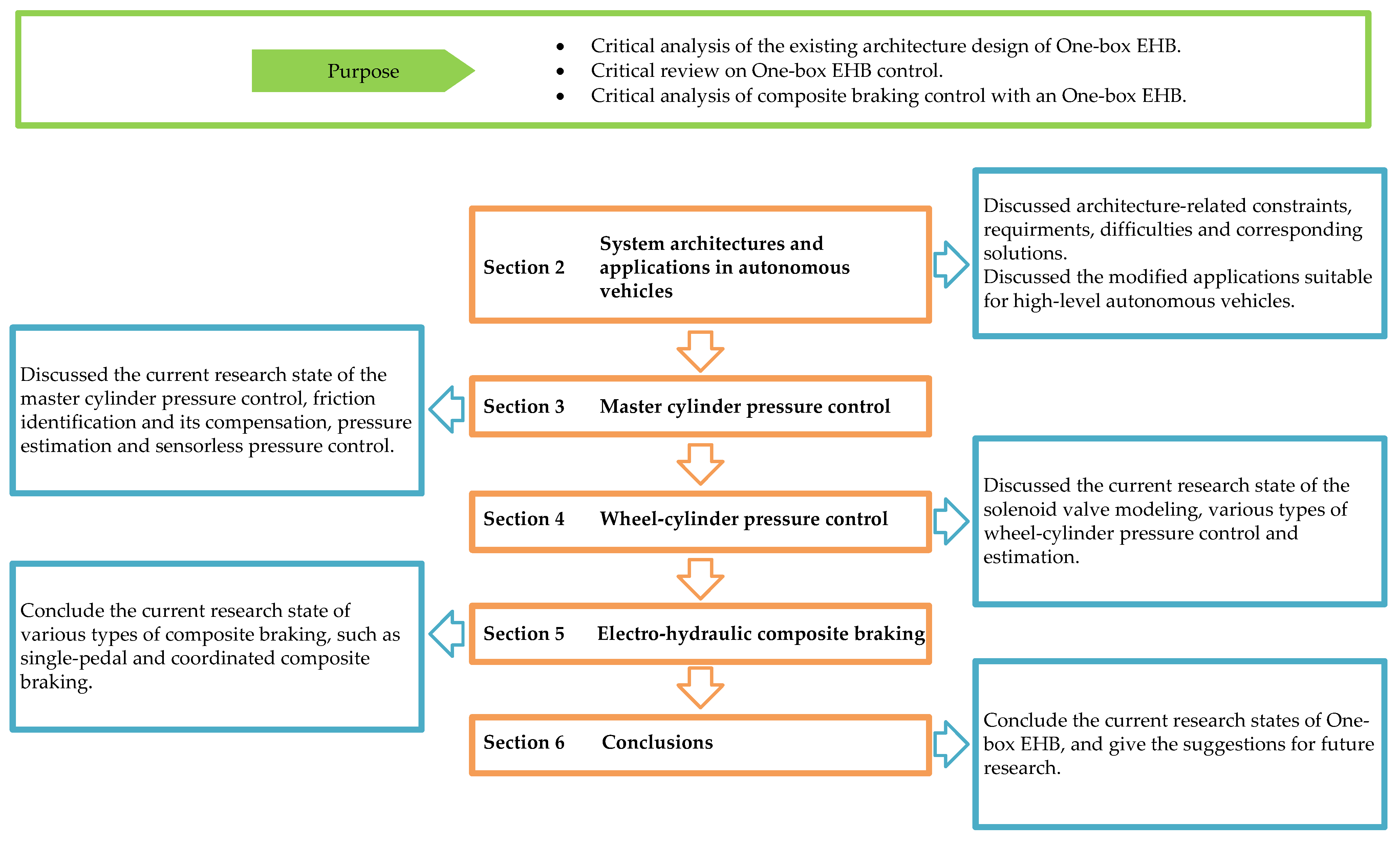
:1. Introduction
- Highly integrated system architecture design
- Robust master cylinder and wheel-cylinder hydraulic pressure control
- Multi-objective-optimized composite braking control
2. System Architectures and Applications in Autonomous Vehicles
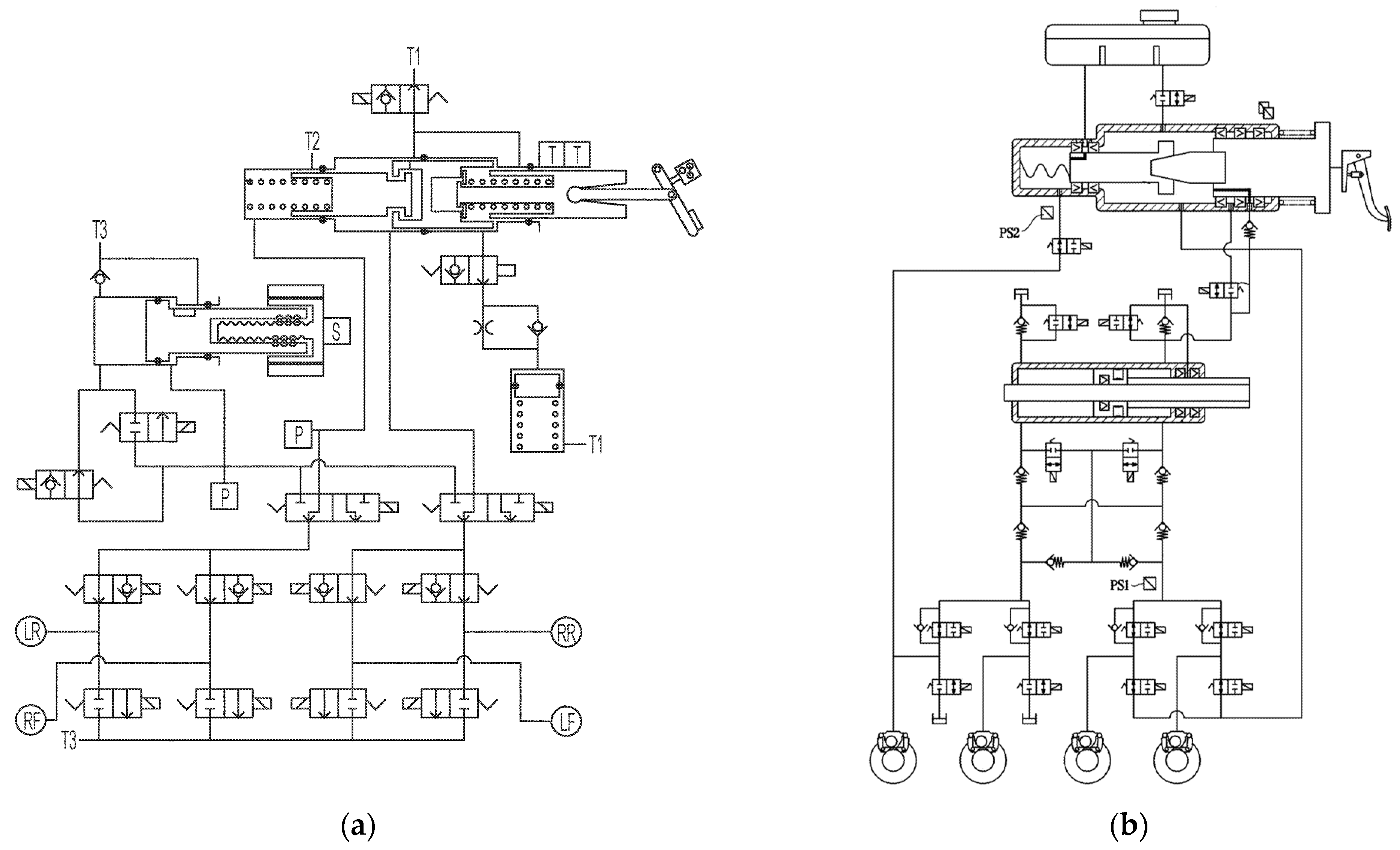
2.1. System Architectures
2.2. Applications in Autonomous Vehicles
3. Master Cylinder Pressure Control
3.1. Pressure Control
3.2. Friction Model and Its Compensation
3.2.1. Experiments and Identification
3.2.2. Compensation and Control
3.3. Pressure Estimation and Sensorless Pressure Control
4. Wheel-Cylinder Pressure Control
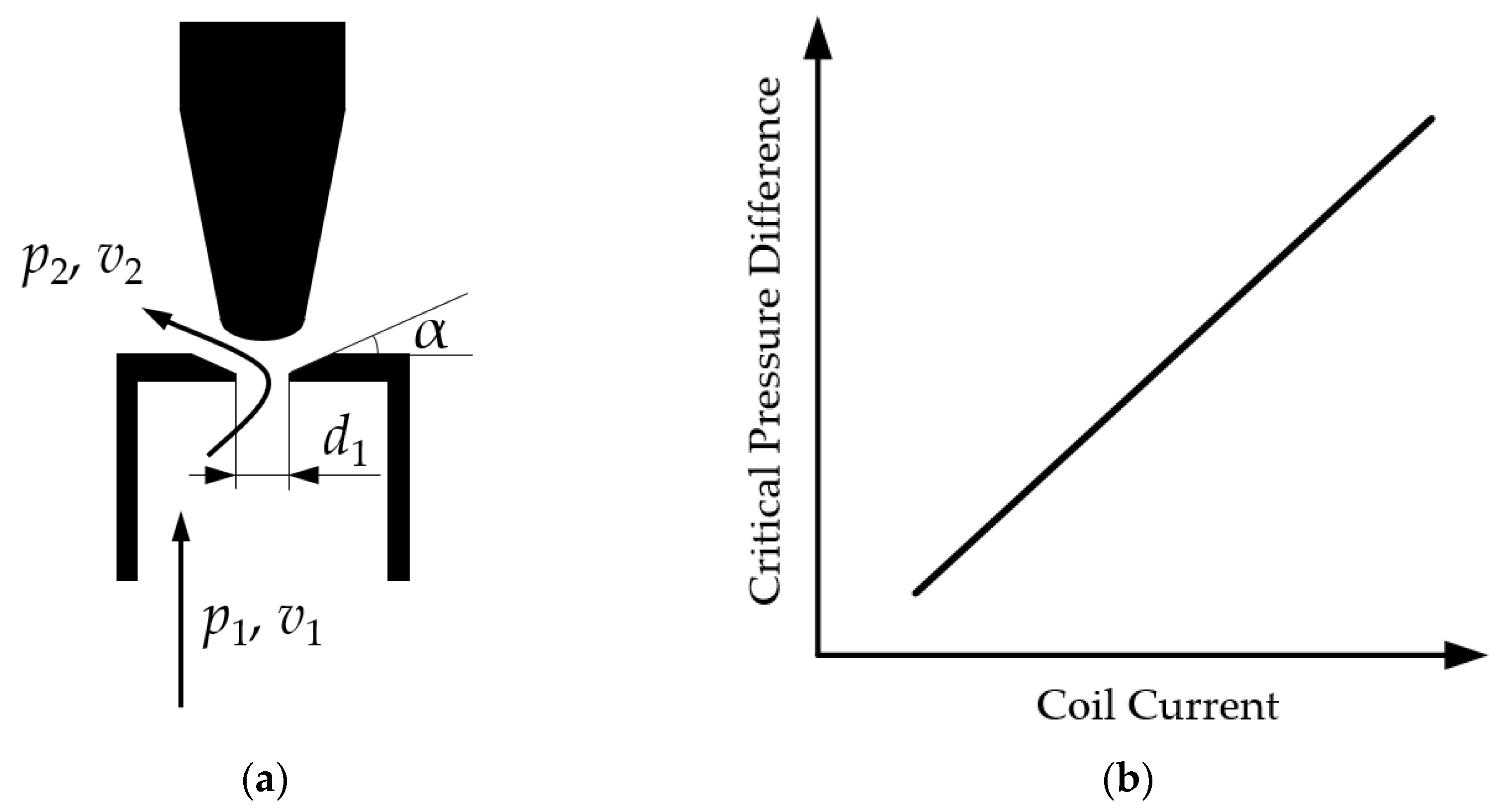
4.1. Modeling of Solenoid Valves

4.2. High-Frequency On-Off Control
4.3. Pressure Difference Control
4.4. Valve Spool Displacement Control
4.5. Wheel-Cylinder Pressure Estimation
4.6. Four Wheel Pressures Coordinated Control
5. Electro-Hydraulic Composite Braking
5.1. Parallel Composite Braking System
5.2. Single-Pedal Braking System
5.3. Coordinated Composite Braking System
5.3.1. Single-Channel Composite Braking System
5.3.2. Dual-Channel Composite Braking System
5.3.3. Multi-Objective Optimization of Composite Braking Systems
5.3.4. Dynamic Coordination of Composite Braking Systems
6. Conclusions
6.1. System Architecture Design
6.2. Master Cylinder Pressure Control
6.3. Wheel-Cylinder Pressure Control
6.4. Electro-Hydraulic Composite Braking Control
Author Contributions
Funding
Institutional Review Board Statement
Informed Consent Statement
Data Availability Statement
Conflicts of Interest
References
- Deng, X.; Wang, L.; Gui, J.; Jiang, P.; Chen, X.; Zeng, F.; Wan, S. A review of 6G autonomous intelligent transportation systems: Mechanisms, applications and challenges. J. Syst. Archit. 2023, 142, 102929. [Google Scholar] [CrossRef]
- Tyagi, A.K.; Sreenath, N. Intelligent transportation system: Past, present, and future. In Intelligent Transportation Systems: Theory and Practice; Prasenjit, C., Anjali, A., Eds.; Springer: Singapore, 2023; pp. 23–47. [Google Scholar]
- Zhang, Y.; Yao, D.-Y.; Li, L.; Pei, H.; Yan, S.; Ge, J. Technologies and Applications for Intelligent Vehicle-infrastructure Cooperation Systems. J. Transp. Syst. Eng. Inf. Technol. 2021, 21, 40. [Google Scholar]
- Wang, P.; Bai, S.; Wang, Y.; Liu, W.; Li, M.E. Research on Generational Evolution of Autonomous Transportation System in Autonomous Driving Scenario. In Proceedings of the 22nd COTA International Conference of Transportation Professionals, Changsha, China, 8–11 July 2022. [Google Scholar]
- Carrese, F.; Sportiello, S.; Zhaksylykov, T.; Colombaroni, C.; Carrese, S.; Papaveri, M.; Patella, S.M. The Integration of Shared Autonomous Vehicles in Public Transportation Services: A Systematic Review. Sustainability 2023, 15, 13023. [Google Scholar] [CrossRef]
- ESP® hev. Available online: https://www.bosch-mobility.com/en/solutions/driving-safety/esp-hev-module/ (accessed on 23 November 2023).
- Kohl, A.; Wichenhofer, T. Method for Operating a Braking System and Braking System. US Patent US20200001846A1, 2 January 2020. [Google Scholar]
- Wagner, J.; Kranich, M.; Taubitz, N.; Collins, R.; Zahariev, S.; Strehle, A. Robert Bosch GmbH. Method for Controlling an Electronically Slip-controllable Power Braking System. US Patent US20190359191A1, 28 November 2019. [Google Scholar]
- Yu, W.; Hawley, S. Method of Controlling a Vehicle Brake System. US Patent US20200070793A1, 5 March 2020. [Google Scholar]
- Kim, J. Electronic Brake System. US Patent US20230174037A1, 8 June 2023. [Google Scholar]
- Kim, J.; Seongho, C. Electronic Brake System and Operating Method Thereof. WO Patent WO 2022146053A1, 7 July 2022. [Google Scholar]
- Yong, C.S.; Jee, S.L.; Wan, K.J. Apparatus and Method for Controlling ESC-Integrated Regenerative Braking System. US Patent US11597368B2, 7 March 2023. [Google Scholar]
- United Nations. Uniform Provisions Concerning the Approval of Passenger Cars with Regard to Braking. UN Regulation No. 13-H. Available online: https://unece.org/transport/vehicle-regulations-wp29/standards/addenda-1958-agreement-regulations-0-20 (accessed on 23 November 2023).
- Park, Y. Electric Brake System and Control Method Thereof. US Patent US11084473B2, 10 August 2021. [Google Scholar]
- Briesewitz, R.; Dolmaya, J. Brake-by-wire Braking System Having at least One Brake Circuit, Method for Operating the Braking System and Diagnosis Valve for a Braking System of This Type. US Patent US20210300314A1, 30 September 2021. [Google Scholar]
- Biller, H. Brake System for Motor Vehicles and Method for Operating a Brake System. US Patent US11639164B2, 2 May 2023. [Google Scholar]
- Brenn, M.; Ullrich, T. Method for Operating a Braking System, and Braking System. US Patent US20220073048A1, 10 March 2022. [Google Scholar]
- Reuter, D.F.; Luo, D. Electro-Hydraulic Brake System. EP Patent EP4001033B1, 18 November 2021. [Google Scholar]
- Jeong, H. Electric Brake System and Operating Method Thereof. US Patent US10857988B2, 8 December 2020. [Google Scholar]
- Yong, C.S. Apparatus for Controlling Anti Lock Brake System of ESC Integrated Brake System and Method Thereof. US Patent US 11752990B2, 12 September 2023. [Google Scholar]
- Courth, C.; Seidel, A.; Lohse, U.; Neu, A.; Caspari, R. Continental Teves AG and Co oHG. Method for Monitoring a Hydraulic Brake System for a Motor Vehicle and Brake System. US Patent US20210245725A1, 12 August 2021. [Google Scholar]
- Henning, W. Method and Control Unit for Operating a Braking System and Braking System. US Patent US11230276B2, 25 January 2022. [Google Scholar]
- SAE International. Taxonomy and Definitions for Terms Related to Driving Automation Systems for On-Road Motor Vehicles. SAE J3016, April 2021. Available online: https://www.sae.org/standards/content/j3016_202104/ (accessed on 11 December 2023).
- Bauer, U.; Brand, M.; Maucher, T. Integrated Power Brake—Modular Set Extension for Highly Automated Driving. In 8th International Munich Chassis Symposium 2017; Springer: Wiesbaden, Germany, 2017. [Google Scholar]
- Bareiss, A.; Reiner, J.; Zander, T. Electro-Hydraulic Power Vehicle-Brake System for an Autonomous Driving Land Vehicle. US Patent US20190344767A1, 14 November 2019. [Google Scholar]
- Zipfel, T.; Nakayasu, Y.; Rizzo, J. Brake Architecture for Automated Driving. US Patent US20170341630A1, 30 November 2017. [Google Scholar]
- Tarandek, K.; Feigel, H.J.; Kurbasa, J.; Bouzid, R.; Leiter, R.; Jeong, H.J.; Jung, H.C. Electronic Brake System and Control Method Thereof. US Patent US20220194339A1, 23 January 2022. [Google Scholar]
- Campau, G.P. Vehicle Brake System with Auxiliary Control Unit. US Patent US20200216052A1, 8 July 2020. [Google Scholar]
- Hong, K. Electronic Brake System and Control Method Therefor. US Patent US20230029756A1, 2 February 2023. [Google Scholar]
- Kim, M.; Kim, S.W.; Han, S. Control Device Structure of Brake System. US Patent US20220340112A1, 27 October 2022. [Google Scholar]
- Yang, I.-J.; Choi, K.; Huh, K. Development of an Electric Booster System Using Sliding Mode Control for Improved Braking System. Int. J. Automot. Technol. 2012, 13, 1005–1011. [Google Scholar] [CrossRef]
- Todeschini, F.; Corno, M.; Panzani, G.; Savaresi, S.M. Adaptive position–pressure control of a brake by wire actuator for sport motorcycles. Eur. J. Control 2014, 20, 79–86. [Google Scholar] [CrossRef]
- Wang, Z.; Yu, L.; Wang, Y.; You, C.; Ma, L.; Song, J. Prototype of Distributed Electro-Hydraulic Braking System and its Fail-Safe Control Strategy. SAE Technical Paper 2013-01-2066. 2013. Available online: https://www.sae.org/publications/technical-papers/content/2013-01-2066/ (accessed on 11 December 2023).
- Chen, L.; Yu, Y.; Luo, J. Master Cylinder Oil Pressure Following Control Algorithm of Electric Power Assisted Braking System Based on Fuzzy PID Controller. In Proceedings of the 2022 4th International Conference on Artificial Intelligence and Advanced Manufacturing (AIAM), Hamburg, Germany, 7–9 October 2022. [Google Scholar]
- Zhao, J.; Hu, Z.; Zhu, B. Pressure Control for Hydraulic Brake System Equipped with an Electro-Mechanical Brake Booster. SAE Technical Paper 2018-01-0329. 2018. Available online: https://www.sae.org/publications/technical-papers/content/2018-01-0829/ (accessed on 11 December 2023).
- Yang, W.; Wu, J.; He, R.; Zhu, B.; Zhao, J.; Chen, Z. Pressure Tracking Control of Electro-Mechanical Brake Booster System. SAE SAE Technical Paper 2020-01-0211. 2020. Available online: https://www.sae.org/publications/technical-papers/content/2020-01-0211/ (accessed on 11 December 2023).
- Zhao, J.; Chen, Z.; Zhu, B.; Wu, J. Precise Active Brake-Pressure Control for a Novel Electro-Booster Brake System. IEEE Trans. Ind. Electron. 2020, 67, 6. [Google Scholar] [CrossRef]
- Wang, J.; Wu, J.; He, R.; Chen, Z. Pressure Optimization Control of Electro-Mechanical Brake System in the Process of ABS Working. SAE SAE Technical Paper 2019-01-1104. 2019. Available online: https://www.sae.org/publications/technical-papers/content/2019-01-1104/ (accessed on 11 December 2023).
- Wang, B.; Wang, M.; Jiang, Y.; Shangguan, W.B. A Research on Modeling and Pressure Control of Integrated Electro-Hydraulic Brake System. SAE SAE Technical Paper 2021-01-0130. 2021. Available online: https://www.sae.org/publications/technical-papers/content/2021-01-0130/ (accessed on 11 December 2023).
- De Castro, R.; Todeschini, F.; Araujo, R.E.; Savaresi, S.M.; Corno, M.; Freitas, D. Adaptive-robust friction compensation in a hybrid brake-by-wire actuator. Proc. IMechE Part I J. Syst. Control Eng. 2014, 228, 769–786. [Google Scholar] [CrossRef]
- Ji, Y.; Zhang, J.; He, C.; Ma, R.; Hou, X.; Hu, H. Constraint performance pressure tracking control with asymmetric continuous friction compensation for booster based brake-by-wire system. Mech. Syst. Signal Process. 2022, 174, 109083. [Google Scholar] [CrossRef]
- Wei, H.; Lu, X.; Zhuoping, Y. A novel pressure control strategy of an electro-hydraulic brake system via fusion of control signals. Proc. IMechE Part D J. Automob. Eng. 2019, 233, 3342–3357. [Google Scholar]
- Chen, Z.; Huang, C.; Liu, Z.; Liu, Y.; Wang, X.; Shi, B.; Li, L. An Offset-Free Explicit Model Predictive Pressure Controller for Integrated Braking System. IEEE Trans. Transp. Electrif. 2023, 3298001. [Google Scholar] [CrossRef]
- Yu, Z.; Xu, S.; Xiong, L.; Guang, X. Robustness Hydraulic Pressure Control System of Integrated-electro-hydraulic Brake System. J. Mech. Eng. 2015, 51, 16. [Google Scholar] [CrossRef]
- Shangguan, W.-B.; Liang, T.-Q.; Jiang, K.-H. Modeling and Pressure Control of Integrated Electro-Hydraulic Brake System. Trans. Beijing Inst. Technol. 2019, 39, 4. [Google Scholar]
- Todeschini, F.; Corno, M.; Panzani, G.; Fiorenti, S.; Savaresi, S.M. Adaptive Cascade Control of a Brake-By-Wire Actuator for Sport Motorcycles. IEEE/ASME Trans. Mechatron. 2015, 20, 3. [Google Scholar] [CrossRef]
- Todeshini, F.; Fornentin, S.; Panzani, G.; Corno, M.; Sacaresi, S.M.; Zaccarian, L. Nonlinear Pressure Control for BBW Systems via Dead-Zone and Antiwindup Compensation. IEEE Trans. Control. Syst. Technol. 2016, 24, 4. [Google Scholar] [CrossRef]
- Wu, J.; Chen, P.; Zhao, J.; He, R. Active Braking of an Electronic Brake Booster Facing Intelligent Automobile. Int. J. Perform. Eng. 2018, 14, 8. [Google Scholar] [CrossRef]
- Chen, Z.; Zhu, B.; Zhao, J.; Wu, J. Multi-closed-loop Pressure Control Strategy Considering Nonlinear Characteristics of Electro-booster Brake System. J. Mech. Eng. 2023, 59, 4. [Google Scholar]
- Zhu, B.; Zhang, Y.-H.; Zhao, J. Precise Control Method for Active Brake Pressure Based on an Integrated Braking Control System. China J. Highw. Transp. 2021, 34, 9. [Google Scholar]
- Jiang, L.; Shi, Q.; Wei, Y.; He, Y.; He, Z.; He, L. Electro-hydraulic braking dynamics for pressure demand control of brake-by-wire system. Proc. IMechE Part D J. Automob. Eng. 2022, 1–14. [Google Scholar] [CrossRef]
- Zhao, J.; Deng, Z.; Zhu, B.; Chang, T.; Chen, Z. Sliding Mode Control Based on RBF Network for Hydraulic Pressure in Electric Power-assisted Brake System. J. Mech. Eng. 2020, 56, 24. [Google Scholar]
- Han, W.; Xiong, L.; Yu, Z. Braking pressure control in electro-hydraulic brake system based on pressure estimation with nonlinearities and uncertainties. Mech. Syst. Signal Process. 2019, 131, 703–727. [Google Scholar] [CrossRef]
- Han, W.; Xiong, L.; Yu, Z.; Zhuo, G.; Leng, B.; Xu, S. Integrated Pressure Estimation and Control for Electro-hydraulic Brake Systems of Electric Vehicles Considering Actuator Characteristics and Vehicle Longitudinal Dynamics. IEEE/ASME Trans. Mechatron. 2023, 28, 1. [Google Scholar] [CrossRef]
- Shi, B.; Xiong, L.; Yu, Z. Pressure Estimation Based on Vehicle Dynamics Considering the Evolution of the Brake Linings’ Coefficient of Friction. Actuators 2021, 10, 76. [Google Scholar] [CrossRef]
- Gao, X.; Yang, Y.; Zhao, X.; Li, C. Non-linear dynamic modelling of a switching valve driven by pulse width modulation in the hydraulic braking system of a vehicle. Proc. IMechE Part D J. Automob. Eng. 2017, 231, 1511–1529. [Google Scholar] [CrossRef]
- Meng, A.; Garris, C.; Wei, L.; Liu, H. Visual System Analysis of High Speed On-Off Valve Based on Multi-Physics Simulation. SAE Technical Paper 2022-01-0391. 2022. Available online: https://www.sae.org/publications/technical-papers/content/2022-01-0391/ (accessed on 11 December 2023).
- Sorniotti, A.; Velardocchia, M. Hardware-In-the-Loop (HIL) Testing of ESP (Electronic Stability Program) Commercial Hydraulic Units and Implementation of New Control Strategies. SAE Technical Paper 2004-01-2770. 2004. Available online: https://www.sae.org/publications/technical-papers/content/2004-01-2770/ (accessed on 11 December 2023).
- O’Dea, K. Anti-Lock Braking Performance and Hydraulic Brake Pressure Estimation. SAE Technical Paper 2005-01-1061. 2005. Available online: https://www.sae.org/publications/technical-papers/content/2005-01-1061/ (accessed on 11 December 2023).
- Ding, N.; Pan, W.; Fang, Y. Measurement of Hydraulic Pressure Response for ABS and Fine Regulation of Pressure. Chin. J. Mech. Eng. 2004, 40, 6. [Google Scholar] [CrossRef]
- Chen, Z.; Wu, J.; Zhu, B. Accurate Pressure Control Strategy of Electronic Stability Program Based on the Building Characteristics of High-Speed Switching Valve. SAE Technical Paper 2019-01-1107. 2019. Available online: https://www.sae.org/publications/technical-papers/content/2019-01-1107/ (accessed on 11 December 2023).
- Zhang, J.; Lv, C.; Yue, X.; Li, Y.; Yuan, Y. Study on a linear relationship between limited pressure difference and coil current of on/off valve and its influential factors. ISA Trans. 2014, 53, 150–161. [Google Scholar] [CrossRef] [PubMed]
- Lv, C.; Zhang, J.; Li, Y.; Sun, D.; Yuan, Y. Hardware-in-the-loop simulation of pressure-difference-limiting modulation of the hydraulic brake for regenerative braking control of electric vehicles. Proc. IMechE Part D J. Automob. Eng. 2014, 228, 649–662. [Google Scholar] [CrossRef]
- Jing, H.; Dong, L.; Feng, R. Active Pressure Control and Experimental Application Based on Automotive Hydraulic Control Unit. In Proceedings of the 41st Chinese Control Conference, Hefei, China, 25–27 July 2022. [Google Scholar]
- Lv, C.; Wang, H.; Cao, D. High-Precision Hydraulic Pressure Control Based on Linear Pressure-Drop Modulation in Valve Critical Equilibrium State. IEEE Trans. Ind. Electron. 2017, 64, 10. [Google Scholar] [CrossRef]
- Wang, W.; Song, J.; Li, L.; Li, H. High speed on-off solenoid valve with proportional control based on high frequency PWM control. J. Tsinghua Univ. (Sci. Tech.) 2011, 5, 5. [Google Scholar]
- Zhao, X.; Li, L.; Song, J.; Li, C.; Gao, X. Linear Control of Switching Valve in Vehicle Hydraulic Control Unit Based on Sensorless Solenoid Position Estimation. IEEE Trans. Ind. Electron. 2016, 63, 7. [Google Scholar] [CrossRef]
- Zhao, X.; Xu, W.-B.; Liu, G. Pressure Estimation and Pressure Control of Hydraulic Control Unit in Electric-Wheel Vehicle. Math. Probl. Eng. 2020, 2020, 6576297. [Google Scholar]
- Zhang, Q.; Jin, L.; Zhang, Y.; Li, J. Research on Estimation and Precise Control of Wheel Cylinder Pressure for Integrated Electronic Hydraulic Brake System. In Proceedings of the 2021 China Automation Congress (CAC), Beijing, China, 22–24 October 2021. [Google Scholar]
- Jiang, G.; Miao, X.; Wang, Y.; Chen, J.; Li, D.; Liu, L.; Muhammad, F. Real-time estimation of the pressure in the wheel cylinder with a hydraulic control unit in the vehicle braking control system based on the extended Kalman filter. Proc. IMechE Part D J. Automob. Eng. 2017, 231, 1340–1352. [Google Scholar] [CrossRef]
- Liu, H.; Wei, L.; Liu, H.; Wu, J.; Wang, X. EKF-Based Wheel Cylinder Pressure Estimation of Integrated Braking System. In Proceedings of the 2022 IEEE 25th International Conference on Intelligent Transportation Systems (ITSC), Macau, China, 8–12 October 2022. [Google Scholar]
- Wei, L.; Wang, X.; Li, L. Wheel Pressure Estimation of Hydraulic Integrated Braking System by Fusion Model. In Proceedings of the 2023 9th International Conference on Control, Automation and Robotics, Beijing, China, 21–23 April 2023. [Google Scholar]
- Zhang, J.; Li, L.; Jiang, H.; Liu, Q.; Wang, Y.; Yuan, W.; Wu, J.; Zhang, X.; Chen, Z. Active Brake Wheel Cylinder Pressure Control Based On Integrated Electro-Hydraulic Brake System; SAE Technical Paper 2022-01-0293. 2022. Available online: https://www.sae.org/publications/technical-papers/content/2022-01-0293/ (accessed on 11 December 2023).
- Han, W.; Xiong, L.; Yu, Z. Analysis and Optimization of Minimum Hydraulic Brake-by-Wire System for Wheeled Vehicles Based on Queueing Theory. IEEE Trans. Veh. Technol. 2021, 70, 12. [Google Scholar] [CrossRef]
- Liu, H.; He, R.; Deng, W.; Yang, S.; Wu, J.; Chen, P. Research on a Novel Electro-Hydraulic Brake System and Pressure Control Strategy. SAE Technical Paper 2018-01-0764. 2018. Available online: https://www.sae.org/publications/technical-papers/content/2018-01-0764/ (accessed on 11 December 2023).
- Ji, Y.; Zhang, J.; He, C.; Hou, X.; Liu, W.; Han, J. Wheel Braking Pressure Control Based on Central Booster Electrohydraulic Brake-by-Wire System. IEEE Trans. Transp. Electrif. 2023, 9, 1. [Google Scholar] [CrossRef]
- Siddiqui, O.; Simacek, D.; Hoang, R.; Famiglietti, N.; Nguyen, B.; Landerville, J. Characterizing Regenerative Coast-Down Deceleration in Tesla Model 3, S, and X. SAE Technical Paper 2020-01-0883. 2020. Available online: https://www.sae.org/publications/technical-papers/content/2020-01-0883/ (accessed on 11 December 2023).
- Vigil, C.M.; Kaayal, O.; Szepelak, A. Quantifying the Deceleration of Various Electric Vehicles Utilizing Regenerative Braking. SAE Technical Paper 2023-01-0623. 2023. Available online: https://www.sae.org/publications/technical-papers/content/2023-01-0623/ (accessed on 11 December 2023).
- He, H.; Wang, C.; Jia, H.; Cui, X. An intelligent braking system composed single-pedal and multi-objective optimization neural network braking control strategies for electric vehicle. Appl. Energy 2020, 259, 114172. [Google Scholar] [CrossRef]
- He, H.; Wang, C.; Jia, H. A single-pedal regenerative braking control strategy of accelerator pedal for electric vehicles based on adaptive fuzzy control algorithm. In Proceedings of the CUE2018-Applied Energy Symposium and Forum 2018: Low Carbon Cities and Unban Energy Systems, Shanghai, China, 5–7 June 2018. [Google Scholar]
- Van Boekel, J.J.; Besselink, I.J.; Nijmeijer, H. Design and realization of a One-Pedal-Driving algorithm for the TU/e Lupo EL. In Proceedings of the EVS28, Goyang, Republic of Korea, 3–6 May 2015. [Google Scholar]
- Shi, Q.; He, Z.; Wei, Y.; Wang, M.; Zheng, X.; He, L. Single Pedal Control of Battery Electric Vehicle by Pedal Torque Demand With Dynamic Zero Position. IEEE Trans. Intell. Transp. Syst. 2022, 23, 11. [Google Scholar] [CrossRef]
- Kwak, K.H.; He, Y.; Kim, Y.; Chen, Y.M.; Fan, S.; Holmer, J.; Lee, J.H. Desired Relative Distance Model-based Personalized Braking Algorithm for One-pedal Driving of Electric Vehicles. IFAC 2022, 55, 62–67. [Google Scholar] [CrossRef]
- Won, M.W. A Study on the Improvement of EV One-Pedal Driving System Interface and Cost Reduction. SAE Technical Paper 2022-01-0645. 2022. Available online: https://www.sae.org/publications/technical-papers/content/2022-01-0645/ (accessed on 11 December 2023).
- Kolarsky, J.; Kunz, M.; Strengert, S.; Vollert, H. Method for Operating a Regenerative Brake System of a Vehicle, Control Device for a Regenerative Brake System of a Vehicle, and Regenerative Brake System. US Patent US9827965B2, 28 November 2017. [Google Scholar]
- Zhao, J.; Hu, Z.; Zhu, B. Regenerative Braking Pedal Decoupling Control for Hydraulic Brake System Equipped with an Electro-Mechanical Brake Booster. SAE Technical Paper 2019-01-1108. 2019. Available online: https://www.sae.org/publications/technical-papers/content/2019-01-1108/ (accessed on 11 December 2023).
- Zhao, X.; Li, L.; Wang, X.; Mei, M.; Liu, C.; Song, J. Braking force decoupling control without pressure sensor for a novel series regenerative brake system. Proc. IMechE Part D J. Automob. Eng. 2019, 233, 1750–1766. [Google Scholar] [CrossRef]
- Watanabe, S.; Yamamoto, T.; Masuda, Y.; Yamakita, H. Electronically Controlled Brake System with Two-Channel Pressure Control for Electric Vehicles; SAE Technical Paper 2023-01-0663. 2023. Available online: https://www.sae.org/publications/technical-papers/content/2023-01-0663/ (accessed on 11 December 2023).
- Yuan, Y.; Zhang, J.; Lv, C.; Li, Y. Design and Performance Analysis of a Novel Regenerative Braking System for Electrified Passenger Vehicles. SAE Technical Paper 2016-01-0438. 2016. Available online: https://www.sae.org/publications/technical-papers/content/2016-01-0438/ (accessed on 11 December 2023).
- Yuan, Y.; Zhang, J.; Li, Y.; Lv, C. Regenerative Brake-by-Wire System Development and Hardware-in-Loop Test for Autonomous Electrified Vehicle. SAE Technical Paper 2017-01-0401. 2017. Available online: https://www.sae.org/publications/technical-papers/content/2017-01-0401/ (accessed on 11 December 2023).
- Yuan, Y.; Zhang, J.; Li, Y.; Li, C. A Novel Regenerative Electrohydraulic Brake System: Development and Hardware-in-Loop Tests. IEEE Trans. Veh. Technol. 2018, 67, 12. [Google Scholar] [CrossRef]
- Li, C.; He, C.; Yuan, Y.; Zhang, J. Co-simulation on Performance Evaluation of a New Electronic Control Hydraulic Braking System. In Proceedings of the IAEAC 2018, Chongqing, China, 12–14 October 2018. [Google Scholar]
- Lv, C.; Zhang, J.; Li, Y.; Yuan, Y. Regenerative Braking Control Algorithm for an Electrified Vehicle Equipped with a By-Wire Brake System. SAE Technical Paper 2014-01-1791. 2014. Available online: https://www.sae.org/publications/technical-papers/content/2014-01-1791/ (accessed on 11 December 2023).
- Hou, X.; Zhang, J.; Zhang, Z.; He, C. Analysis of Active Collision Avoidance Performance Based on Cooperative Regenerative Auxiliary Braking System. SAE Technical Paper 2019-01-5027. 2019. Available online: https://www.sae.org/publications/technical-papers/content/2019-01-5027/ (accessed on 11 December 2023).
- Li, C.; He, C.; Yuan, Y.; Zhang, J. Braking Evaluation of Integrated Electronic Hydraulic Brake System Equipped in Electric Vehicle. In Proceedings of the ITNEC 2019, Chengdu, China, 15–17 March 2019. [Google Scholar]
- Guo, H.; Zhao, X.; Liu, J.; Zhu, F.; Chen, H.; Cao, D. Hierarchical coordinated control strategy for regenerative braking energy recuperation with an electrobooster. Proc. IMechE Part D J. Automob. Eng. 2022, 1–14. [Google Scholar] [CrossRef]
- He, C.; Wang, G.; Gong, Z.; Xing, Z.; Xu, D. A Control Algorithm for the Novel Regenerative–Mechanical Coupled Brake System with by-Wire Based on Multidisciplinary Design Optimization for an Electric Vehicle. Energies 2018, 11, 2322. [Google Scholar] [CrossRef]
- Wu, T.; Wang, F.; Ye, P. Regenerative Braking Strategy of Dual-Motor EV Considering Energy Recovery and Brake Stability. World Electr. Veh. J. 2023, 14, 19. [Google Scholar] [CrossRef]
- Jiang, B.; Zhang, X.; Wang, Y.; Hu, W. Regenerative braking control strategy of electric vehicles based on braking stability requirements. Int. J. Automot. Technol. 2021, 22, 465–473. [Google Scholar]
- Yu, Z.; Shi, B.; Xiong, L.; Han, W. Coordinated Control under Transitional Conditions in Hybrid Braking of Electric Vehicle. SAE Technical Paper 2018-01-1869. 2018. Available online: https://www.sae.org/publications/technical-papers/content/2018-01-1869/ (accessed on 11 December 2023).
- Li, X.; Li, X.; Wang, X.; Liu, Y.; Song, J.; Ran, X. Transient switching control strategy from regenerative braking to anti-lock braking with a semi-brake-by-wire system. Veh. Syst. Dyn. 2016, 54, 231–257. [Google Scholar] [CrossRef]
- Subramaniyam, K.V.; Subramanian, S.C. Impact of regenerative braking torque blend-out characteristics on electrified heavy road vehicle braking performance. Veh. Syst. Dyn. 2021, 59, 269–294. [Google Scholar] [CrossRef]


| Terminology | Descriptions |
|---|---|
| Service brake | Basic braking ability to decelerate the vehicle effectively. |
| Failure backup | If the One-box EHB fails, the driver can still decelerate the vehicle by pressing the brake pedal. |
| Brake decoupling | The brake pedal travel and wheel-cylinder pressures are coupled in traditional braking systems. Brake decoupling means to break the connection between them. |
| Pedal feel simulator | Since the brake pedal and wheel-cylinders are decoupled, there should be a pedal feel simulator to provide a comfortable brake feeling. |
| Pressure-building unit | The main brake pressure source of the One-box EHB. |
| Single-circuit leakage failure | A brake system has two circuits, each of which is composed of two wheel-cylinders. Two circuits are isolated in traditional brake systems. |
| Redundant braking system | In a high-level autonomous vehicle, if the One-box EHB fails, the redundant braking system should decelerate the vehicle. |
| PV characteristics | A certain relationship between the system pressure and the volume of brake fluid entering the system. |
| Electro-hydraulic composite braking | In electro-hydraulic composite braking, the braking force is provided by hydraulic braking by wheel-cylinders and regenerative braking by the drive motor. |
| Coordinated composite braking | A type of composite braking in which the proportion of hydraulic brake and regenerative brake can be adjusted in real time. |
| Braking force distribution | To coordinate the braking force between the front wheels and rear wheels to achieve better braking stability. |
| Characteristics | Classification | Advantage | Disadvantage |
|---|---|---|---|
| Pressure Building Mode | One-way [7,8,18] | Simple structure | Pressure interruption when replenishing |
| Two-way [9,19,20] | Modification of piston and sealing; additional solenoids | No need to replenish | |
| Three-stage [10] | Modification of piston and sealing; additional solenoids | No need to replenish; can reach higher pressure | |
| Detection of single-circuit leakage failure | Self-check [11,21] | Recognition of the failed location | Not in real-time |
| Pressure drop detection [12,22] | In real-time | Cannot recognize the failed location rapidly | |
| Failure backup of single-circuit leakage failure | Switch to fail-back mode | Simple | Very low deceleration |
| Cut the leakage circuit through solenoid valves [12] | Minimum influence on deceleration | Need fail location recognition | |
| Cut the leakage circuit and build more pressure on the normal circuit [14] | No influence on deceleration | Need fail location recognition | |
| One circuit connected to the brake pedal; the other connected to the motor [15,16,17] | Minimum influence on deceleration | Need a circuit separation valve |
| Characteristics | Classification | Advantage | Disadvantage |
|---|---|---|---|
| Backup Structure | Additional box [25,26,27,28] | Each box is simple; | Take more space; complicated to install |
| Integrated as one-box [30] | Small package; easy to install | Complex; no backup of mechanical parts | |
| Backup capability of the service brake | Four-wheel braking ability | Full use of wheel brakes | Complex hydraulic connections |
| Front-wheel braking ability | Simple hydraulic connections | Not full use of wheel brakes | |
| Multi-level limp strategies | Maximize backup capacity in different failure modes | Not full use of wheel brakes if main One-box totally fails | |
| Backup capability of anti-lock control | Dual-channel control | Simple structure | Cannot utilize the other brake in the same circuit |
| Front-wheel single control | Simple structure | No brake in the rear wheels |
| Control Variable | Control Scheme | Details |
|---|---|---|
| Position control | Sliding mode control [31] | |
| Pressure control | PID | Gain-scheduling PI [33] |
| Increment PID [34] | ||
| Segmented PID [44] | ||
| Cascade control | Pressure-position switch control [32,45] | |
| Pressure-position [36,37,38,46,47,48,49,50] | ||
| Pressure-position-speed [35] | ||
| Others | Sliding mode control [51] | |
| RBF neuro network [52] | ||
| Friction compensation | LuGre model [41] | |
| Coulomb friction, viscous friction and Stribeck model [42] | ||
| Karnopp model [43] | ||
| Control Scheme | Advantage | Disadvantage | Classification |
|---|---|---|---|
| High-frequency on–off control | Simple and robust | Noise, step control of pressure | Duty control [58] |
| variable gain PID control [59] | |||
| Pressure difference control | Accurate | Very slow to converge | Open-loop control [60,61] |
| PID [62] | |||
| Sliding mode control [63] | |||
| Valve spool displacement control | Accurate | Difficult to verify the spool displacement | Sliding mode control [65] |
| Sliding mode variable structure control [66] |
| Control Scheme | Classification |
|---|---|
| Single-channel [83,84] | / |
| Dual-channel | Braking force distributed as an ideal distribution [86] |
| Braking force distributed as the original vehicle [87,88,89,90] | |
| Multi-objective optimization | Mas energy recovery rate, braking safety, and braking force distribution as objectives [94] |
| Ideal braking stability and ideal energy recovery rate as objectives [95] | |
| The lowest difference between the four-wheel utilization adhesion coefficient and the braking intensity as objectives [97] | |
| Dynamic coordination | double-closed-loop feedback control strategy [98] |
| Compensate the hydraulic braking through the regenerative braking when ABS [99] |
Disclaimer/Publisher’s Note: The statements, opinions and data contained in all publications are solely those of the individual author(s) and contributor(s) and not of MDPI and/or the editor(s). MDPI and/or the editor(s) disclaim responsibility for any injury to people or property resulting from any ideas, methods, instructions or products referred to in the content. |
© 2024 by the authors. Licensee MDPI, Basel, Switzerland. This article is an open access article distributed under the terms and conditions of the Creative Commons Attribution (CC BY) license (https://creativecommons.org/licenses/by/4.0/).
Share and Cite
Zhao, X.; Xiong, L.; Zhuo, G.; Tian, W.; Li, J.; Shu, Q.; Zhao, X.; Xu, G. A Review of One-Box Electro-Hydraulic Braking System: Architecture, Control, and Application. Sustainability 2024, 16, 1049. https://doi.org/10.3390/su16031049
Zhao X, Xiong L, Zhuo G, Tian W, Li J, Shu Q, Zhao X, Xu G. A Review of One-Box Electro-Hydraulic Braking System: Architecture, Control, and Application. Sustainability. 2024; 16(3):1049. https://doi.org/10.3390/su16031049
Chicago/Turabian StyleZhao, Xinyu, Lu Xiong, Guirong Zhuo, Wei Tian, Jing Li, Qiang Shu, Xuanbai Zhao, and Guodong Xu. 2024. "A Review of One-Box Electro-Hydraulic Braking System: Architecture, Control, and Application" Sustainability 16, no. 3: 1049. https://doi.org/10.3390/su16031049
APA StyleZhao, X., Xiong, L., Zhuo, G., Tian, W., Li, J., Shu, Q., Zhao, X., & Xu, G. (2024). A Review of One-Box Electro-Hydraulic Braking System: Architecture, Control, and Application. Sustainability, 16(3), 1049. https://doi.org/10.3390/su16031049