Article

Coordinated Hybrid Approach Based on Firefly Algorithm and Particle Swarm Optimization for Distributed Secondary Control and Stability Analysis of Direct Current Microgrids

1
Discipline of Electrical, Electronic and Computer Engineering, University of KwaZulu-Natal, Durban 4041, South Africa
2
Enerzinx, LLC, Ottawa, ON K1P 5J2, Canada
3
Department of Electrical and Computer Engineering, University of Victoria, Victoria, BC V8P 5C2, Canada
*
Author to whom correspondence should be addressed.
Sustainability 2024, 16(3), 1204; https://doi.org/10.3390/su16031204
Submission received: 5 December 2023 / Revised: 23 January 2024 / Accepted: 26 January 2024 / Published: 31 January 2024

Abstract

:
Standalone DC microgrids can potentially influence intelligent energy systems in the future. They accomplish this by employing droop control to smoothly integrate various renewable energy sources (RESs) to satisfy energy demands. This method ensures equitable allocation of load current among RESs, promoting efficiency and smooth operation. Utilizing droop control typically leads to a reduction in the voltage of the DC bus. Hence, to uniformly distribute current among several RESs while simultaneously regulating the DC bus voltage, this research proposes a distributed secondary control technique. The proposed technique ensures fair distribution of current and eliminates bus voltage variations by integrating both current and voltage errors within the designed control loop. An innovative hybrid firefly and particle swarm optimization algorithm (FFA–PSO) is introduced to aid in parameter selection for the distributed control approach, facilitating the attainment of the intended control objectives. A DC microgrid state-space model was developed, which incorporates eigenvalue observation analysis to evaluate the impacts of the optimized secondary distributed control on the stability of the microgrid. A real-time testing setup is built using MATLAB/Simulink® R2022b software. and implemented on a Speedgoat real-time machine to verify the practical performance of the proposed approach in real-world applications. The results showcase the robustness of the proposed control technique in achieving voltage stabilization and even current allocation within the DC microgrid. This is evidenced by minimal oscillations and undershoots/overshoots and swift response times.

1. Introduction

The amount of energy consumed worldwide has significantly increased in recent years, posing a significant threat to the economic sector and sustainable development in meeting current energy demands [1,2]. Proposals to increase energy resources to satisfy the increasing demand have been making the rounds; these include both fossil fuels and alternative energies [3]. However, to lessen the harmful effects of carbon dioxide on the environment, society has emphasised reducing its dependency on fossil fuels over the past decade [4]. This has encouraged the development of power plants that harness renewable energies. According to projections by the U.S. International Energy Agency, there is an anticipated 50% surge in the utilization of clean energy resources between 2019 and 2024 [5]. Conversely, numerous regions, including rural areas, grapple with energy shortages, emphasizing factors such as consumption patterns, social standing, income, and restricted availability of clean, modern, and sustainable energy resources [6,7]. Therefore, in addressing concerns such as the economic aspects of power generation, environmental impact from fossil fuels, limited availability, and electricity shortages, researchers worldwide have developed an integrated approach. This approach combines conventional and non-conventional methods for electricity generation, aiming to promote renewable energy sources (RESs) and mitigate existing issues. However, integrating RESs into the conventional utility grid might incur significant expenses due to losses in unnecessary power conversion stages [8]. Hence, implementing a standalone microgrid—an autonomous system equipped with its own control framework, generation sources, storage systems, and loads—becomes essential in providing power to remote areas while reducing expenses and centralising these resources in a single location [9]. The idea of microgrids emerged over a decade ago; however, numerous associated challenges have prevented its widespread adoption, making it the focus of current research efforts [10]. In the current body of literature, diverse types of microgrids have been employed, encompassing hybrid AC/DC, AC, and DC configurations [11,12]. Presently, DC-based systems are considered to be a better choice for microgrid operation. Their higher efficiency, improved compatibility with consumer electronics, direct interface with various RESs, and energy storage systems (ESSs) contribute to the demand for them [8,13]. When operating in islanded mode, frequency and harmonic-related issues are non-existent. Also, there are no concerns regarding regulating reactive power, and synchronization is not required [14,15]. Addressing specific challenges is crucial to optimize the potential of this microgrid setup. These challenges encompass ensuring compatibility with AC loads and seamlessly transitioning between islanded and on-grid operations [16]. Protecting DC microgrids does present a challenge owing to the lack of zero-crossing current and ground limitations [17]. Sustaining stability in a direct current MG becomes significantly challenging during fault conditions. This difficulty primarily arises from the absence of inherent physical inertia and the resistive impedance characteristic of direct current MG configurations [16,18].
Power electronic converters are commonly used as interfaces in every microgrid. They enable the connection of each distributed energy resource to the shared DC bus [19]. The advent of direct current microgrid technology led to the widespread adoption of DC loads across diverse sectors, including fields like data centres and telecommunication facilities [20]. Many modern electronic devices like televisions, laptop or phone chargers, and LED bulbs require precise DC voltage levels for their operation. Hence, due to these characteristics, direct current MGs can potentially cater to the increasing needs of remote and small communities around the globe [21]. Highlighting the importance of regulating bus voltage and ensuring efficient current distribution within multi-source DC microgrids underscores a critical priority for ongoing research in this field. The traditional droop control method for direct current MGs has been employed in the literature due to its straightforward implementation, stemming from the absence of a communication network requirement [22]. However, this control technique encounters issues such as circulating current regulations, voltage fluctuations, and unbalanced current sharing due to line and droop resistance among the MG converters [9]. Voltage stability and current allocation accuracy are intricately linked to the droop resistance: increasing the droop resistance leads to greater voltage deviations but improves current sharing accuracy and vice versa [23]. Consequently, the traditional droop technique presents several limitations: it faces an inherent load-sharing and voltage control management trade-off, exhibits slow transient response, delivers suboptimal performance with distributed energy resources (DERs), and experiences impedance misalignment among parallel converters, affecting active power distribution. As a result, incorporating a secondary control loop alongside droop control can serve as an additional control layer for DC microgrids [14,18,24]. There are three primary categories of secondary control: decentralized, centralized, and distributed control. In centralized control, the microgrid relies on a single central controller that communicates with all distributed energy resources within the system. This controller must be able to handle all data from components operating within the microgrid [23]. This control method places a significant communication burden, leading to limited control reliability and heavy dependence on the central controller. If there is a communication breakdown or failure of the central controller, the entire system could become inoperative [23,25]. The decentralized control approach alleviates the limitations of centralized control by eliminating the necessity for communication among the DERs. Instead, only local measurements are utilized to implement the control loop for each operating distributed energy source within the microgrid. Deploying a secondary decentralized control system can pose challenges, potentially compromising the overall operational efficiency of the DC microgrid. This stems from the absence of a communication link, limiting access to global information. Consequently, the controller’s output might not adequately counterbalance the required deviation induced by the droop controls [16,23].
Distributed control techniques exhibit characteristics present in both decentralized and centralized control approaches, leveraging the benefits of both types of control approaches. Each active distributed energy source within the MG possesses its own secondary distributed controller, and they establish communication among themselves through digital communication interfaces, typically utilizing a power line or a low-bandwidth communication network to exchange data like bus voltage and DER current output, among other parameters [18,26]. This helps the microgrid sustain complete functionality, even in a controller malfunction or communication link failure scenario, as long as the network remains interconnected. As a result, distributed control can withstand the possibility of one point of failure, enabling the convenient plug-and-play operation of distributed energy resources [14,18]. Recent advancements in distributed control techniques have enabled the implementation of a secondary control loop to achieve its control objectives (current distribution and voltage restoration) in a consensus manner with enhanced levels of reliability, scalability, and robustness. An integral-type secondary distributed control technique, which utilizes event-triggered communication, is presented in [27] to facilitate a balanced distribution of current and guarantee voltage recovery in an autonomous direct current MG. This approach can accomplish control objectives with minimal reliance on aperiodic communication, significantly reducing communication costs. However, it becomes ineffective if the converters do not have access to the bus voltage. Furthermore, this approach considers resistive loads alone, rendering it incapable of accommodating other load types. A cooperative distributed control technique is introduced in [25] for voltage recovery and current allocation in a direct current MG. The approach utilizes a discrete consensus with sparse communication with neighbouring converters, considering the discrete nature of measurements, communication data exchange, and control system implementation. In [28], a supervisory distributed control is introduced, which enables smooth transitions between two separate secondary controls. These distributed controllers are engineered explicitly for current distribution and voltage recovery within the DC microgrid. The constraints associated with this method include transients arising from the constant switching circuit’s operation and the complexity of adjusting multiple control coefficients. A secondary distributed control based on a consensus protocol is introduced in [29] for addressing the issues of current allocation and voltage recovery within a direct current microgrid. The approach utilizes a duo of PI controllers; one focused on voltage recovery and the other assigned to ensure an equitable current allocation. The amendment signals generated by these secondary control loops are transmitted to their respective local primary control loops. While the implementation of this method is simple, it does not provide the precise correction term needed, which can result in a decline in control performance due to this mismatch. In [30], a secondary distributed control approach for DC microgrids is presented. The approach utilizes event-triggered communication to reduce costs. It breaks the secondary control and tertiary optimization hierarchy by simultaneously solving the voltage restoration and power regulation issues in the secondary layer. The practical implementation of the optimization algorithm utilized in this technique still faces certain challenges, such as communication delays, and the limitation of line capacity was also not considered. A fixed-time secondary distributed control approach based on virtual voltage drop was also introduced in [31]. Though the control system accomplished the control objectives associated with voltage control and current allocation within a predefined settling period, the influence of line impedance was not considered in the design. In [32], a distributed iterative algorithm utilizing a game theory approach has been formulated. The technique targets proportionate current allocation and voltage restoration control in a direct current MG. A downside of this approach is the significant computational workload it imposes; it demands an extensive dataset to effectively learn the operations of the direct current MG for optimal performance.
Drawing from the existing literature review, it is clear that designing the secondary control system requires integrating two control loops: one for current distribution and another for voltage recovery. Integrating the control signal at the output of the secondary control system into the primary control loop typically results in a trade-off between voltage restoration and current distribution. Therefore, this research aims to develop a control technique that concurrently achieves both current distribution and voltage recovery, striking a balance between these two objectives. In this article, a distributed control technique is proposed, relying on a linear integration of current allocation and voltage control loops within the layers of the secondary control for a standalone DC MG. The distributed nature ensures robustness in the microgrid’s operation. Each distributed energy resource (DER) within the microgrid has its secondary control system, fostering a distributed setup. However, there is information exchange among the DERs to ensure agreement in their operations. To balance control objectives between current distribution and voltage restoration, a weighting coefficient is introduced, resolving the control trade-off. This weighting coefficient is determined through a meta-heuristic optimization (MHO) technique. Recent findings indicate a significant lack of emphasis on utilizing MHO methods, which are notable for their effectiveness in tackling complex problems and optimizing controller parameters [33]. This oversight pertains to addressing the significant challenges identified in prior research within the secondary control layer of DC microgrids. Addressing these challenges can involve the application of a range of meta-heuristic algorithms. A handful of illustrative algorithms in this category include the gravitational search algorithm, the firefly optimization algorithm (FFA) [34], the particle swarm optimization (PSO) method [35], and the grey wolf optimization (GWO) algorithm [36], inspired from the hierarchical leadership structure observed in grey wolf packs. Other examples include the giant trevally optimizer (GTO) [37], designed based on the giant trevally hunting behaviours; elephant clan optimization (ECO) [38], which is developed by simulating a model of elephant behaviour; the barnacle mating optimizer (BMO) algorithm [39], created using barnacle mating behaviour as a model; the sewing-training-based optimization (STBO) algorithm [40], designed using the task of imparting sewing skills as a model; the ebola optimization search algorithm (EOSA) [41], inspired by the ebola virus transmission mechanism; and the Aquila optimizer (AO) [42], inspired by the Aquila’s strategy of capturing prey. Given their limitations and inherent strengths, it is crucial to emphasize that no individual optimization algorithm can ensure the optimum operational performance of the system. For instance, the strengths of PSO include its straightforward implementation, minimal computational demands, and rapid convergence. However, it also exhibits weaknesses like early convergence or becoming stuck in local optima, along with a slower rate of convergence during exploitation when particles cluster around each other or the global optimum [19]. On the other hand, the FFA is a nature-inspired optimization technique rooted in swarm intelligence, mirroring the behaviour of fireflies in the natural world. the FFA holds certain advantages over the PSO algorithm [34,43]. Specifically, the FFA lacks an individual or specific global best, thereby avoiding the drawbacks associated with becoming trapped in local minima or encountering early convergence. Furthermore, the fireflies within the FFA lack a velocity characteristic. Consequently, this absence helps prevent issues related to fast or slow velocities [34]. While the FFA exhibits strong characteristics in local searches, there are instances where it struggles to break free entirely from local searches, resulting in being trapped in a local minimum [43]. Prior research has proposed integrating multiple algorithms through hybridization to address these challenges with the goal of attaining optimal system performance. Adopting a hybrid FFA–PSO can harness the respective strengths of both the FFA and PSO. The hybrid algorithm under consideration leverages the light intensity operation mechanism from the FFA for local search and integrates a PSO operator for global exploration. This algorithm blend ensures a harmonious equilibrium between exploitation and exploration, harnessing the strengths of both the FFA and PSO algorithms to optimize performance [43]. The algorithm stands out due to its simplicity and user-friendly nature as a potent tool for problem-solving. Moreover, it demonstrates competitive performance when benchmarked against other optimization algorithms [34], and it has proven effective in solving optimization problems [44]. Implementing this method can notably enhance the performance of the secondary control loop in direct current microgrids. Hence, this paper addresses current allocation and voltage recovery challenges in DC MGs. It proposes employing the hybrid FFA–PSO algorithm to dynamically select the newly introduced weighting coefficient incorporated within the secondary control system. It is important to highlight that the proposed technique brings significant contributions, such as better bus voltage restoration within a 5% tolerance, improved current-sharing among parallel DERs in the MG, decreased settling time, and minimized undershoot/overshoot across diverse operating scenarios. Eigenvalue analysis was employed to evaluate the stability of the control method presented in this study. Furthermore, the proposed technique requires less communication bandwidth, resulting in decreased communication costs. To assess the robustness of the newly introduced secondary distributed control technique to guarantee voltage recovery and accurate current allocation within the MG and its practical application in real-world scenarios for direct current MGs, a real-time environment incorporating a Speedgoat real-time digital machine is utilized to develop the direct current MG and implement the proposed secondary control under diverse operating scenarios.
In summary, this study has made the following contributions:
  • A distributed secondary control strategy for a DC microgrid is proposed, incorporating a new weighting parameter that concurrently ensures fair current distribution and eliminates bus voltage variations across several DERs.
  • An innovative FFA-PSO is introduced to aid in the parameter selection for the distributed control approach. This algorithm helps in fulfilling the control objectives of the microgrid.
  • A DC microgrid state-space model that incorporates eigenvalue observation analysis is developed to evaluate the impacts of the optimized secondary distributed control on the stability of the microgrid. This analysis helps in understanding the stability of the system.
  • A real-time testing setup using MATLAB/Simulink® is built and implemented on a Speedgoat real-time machine to verify the practical performance of the proposed approach in real-world applications.
The research structure is shown in Figure 1, while the article has the following layout: Section 2 explores the direct current MG state-space models, incorporating the primary control loop model. The modelling of the newly introduced distributed secondary control technique is outlined in Section 3. Section 4 introduces and formulates the hybrid FFA–PSO tuning method for addressing the discussed problem. The outcomes of evaluating the proposed technique’s performance, along with stability analysis, are detailed in Section 5. Lastly, Section 6 summarizes the achievements attained in this study.

2. DC Microgrid Modelling

In this section, the mathematical model for conducting small-signal analysis of the components within the DC MG is delineated. In this microgrid setup, the DERs are connected in parallel to a common DC bus, and similarly, all microgrid loads are linked to this DC bus. The microgrid’s management and coordination utilize a hierarchical control system architecture that comprises tertiary, secondary, and primary controls. However, this research is confined to examining the secondary and primary levels of control. A state-space (SS) model is developed for a singular distributed energy source converter, incorporating its associated control mechanisms. This model can be expanded to encompass multiple distributed energy sources within a DC microgrid setup.

2.1. DC-DC Buck Converter Modelling

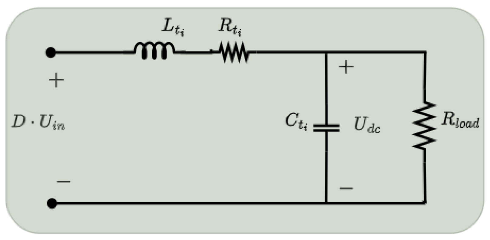
To create the SS model for the buck converter, the equivalent circuit illustrated in Figure 2 adequately captures the converter’s average performance while neglecting its high-frequency dynamics. The converter reduces the input DC voltage ( U i n ) to a lower DC output voltage ( U d c ). The operational characteristics of the converter can be articulated as follows [45]:
d I L t ( t ) d t = D · U i n L t I L t · R L t L t U d c L t ,
d U d c ( t ) d t = I L t C t U d c C t R l o a d ,
where R L t , L t , and C t represent the parasitic inductance resistance, converter inductance, and capacitance, respectively. R l o a d , D, and I L t depict the load resistance, converter duty cycle, and inductor filter current, respectively.
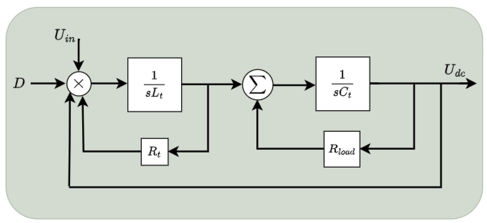
To evaluate the stable operational performance of the converter illustrated in Figure 3, Equations (1) and (2) are transformed into the Laplace domain and rearranged to establish the transfer function, as outlined in (3).
U d c ( s ) D · U i n ( s ) = 1 s 2 + 2 τ ω n s + ω n 2
where
ω n = R L t + R l o a d L t C t R l o a d a n d τ = R L t R l o a d C t + L t 2 ( R L t + R l o a d ) ( L t C t R l o a d )
The parameters C and L of the converter can be inferred from [46]:
C t = Δ i L t 8 Δ v o f s w , L t = D ( U i n U d c ) 2 Δ i L t f s w ,
where Δ i L t , Δ v o , and f s w represent the allowable peak inductor current ripple, allowable peak DC voltage output ripple, and switching frequency for the buck converter, respectively.

2.2. Primary Control Model

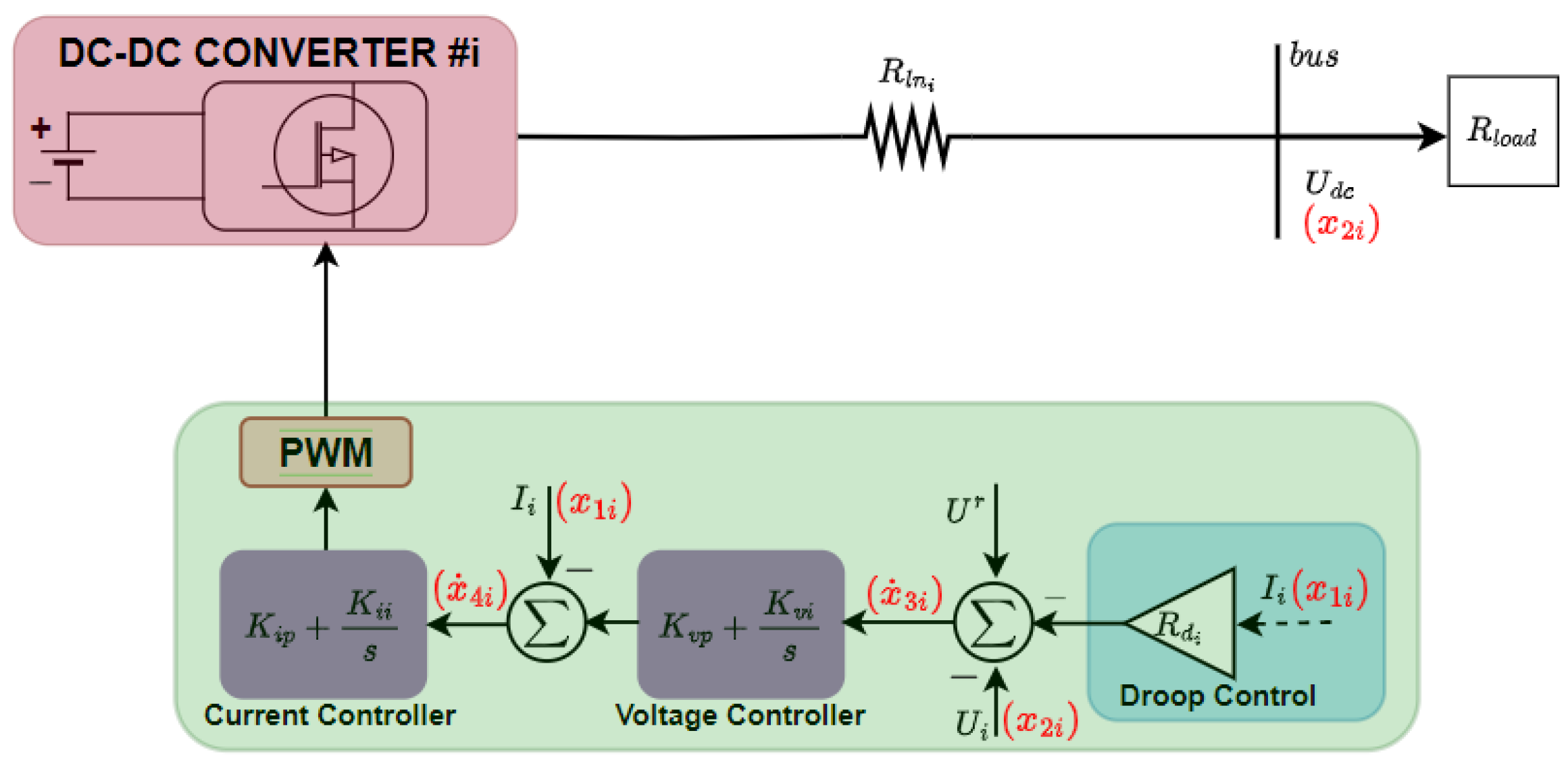
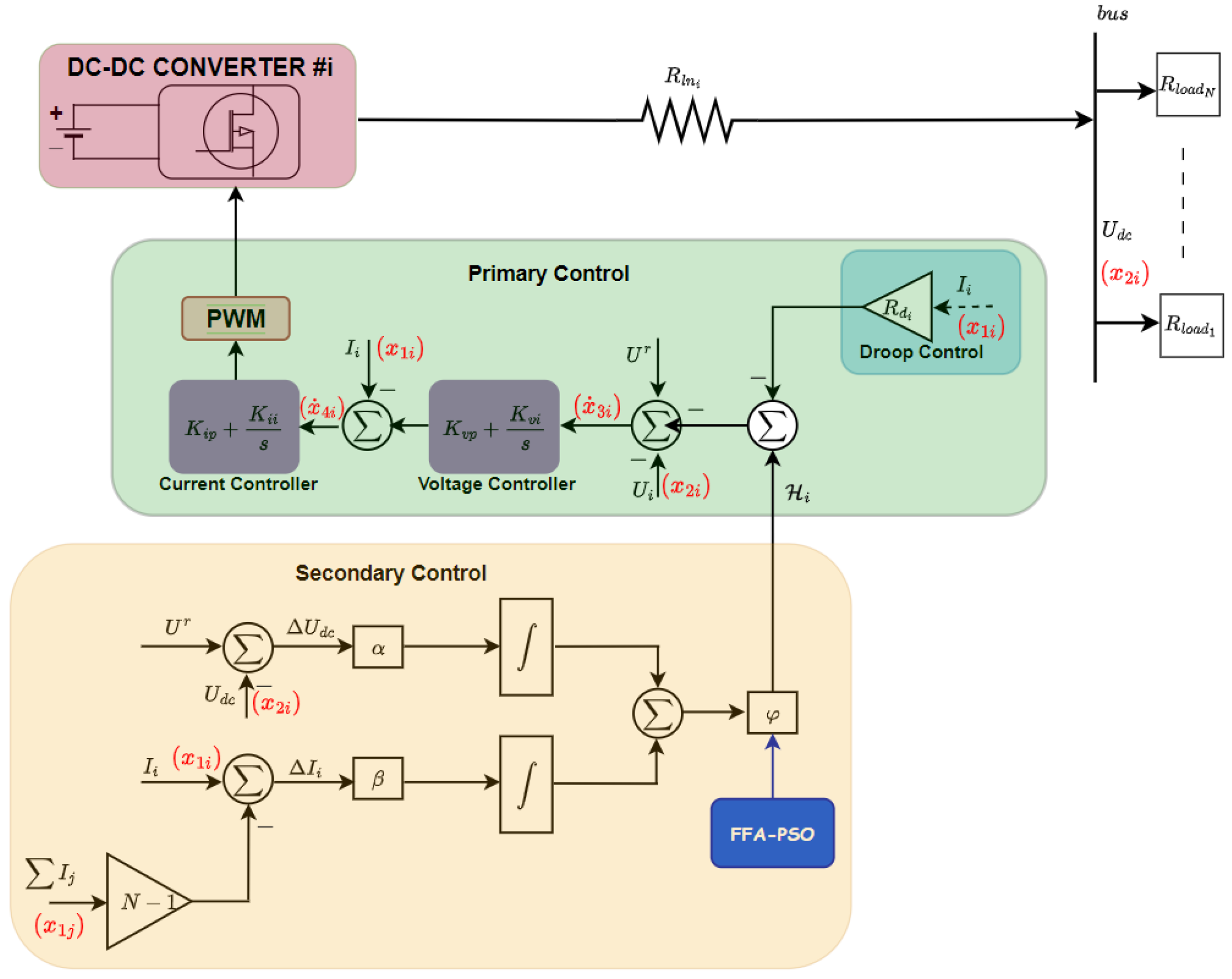
As depicted in Figure 4, the primary control mainly consists of two PI-type controllers—one for voltage control, another for current control—and a P-type controller for droop control. For regulating the DC voltage output, the voltage controller generates a reference signal employed by the current control. Subsequently, the current control generates the duty cycle as a reference for the converter’s PWM to manage the current output. The current control is configured to have a quicker response time compared to the voltage control to prevent instability.
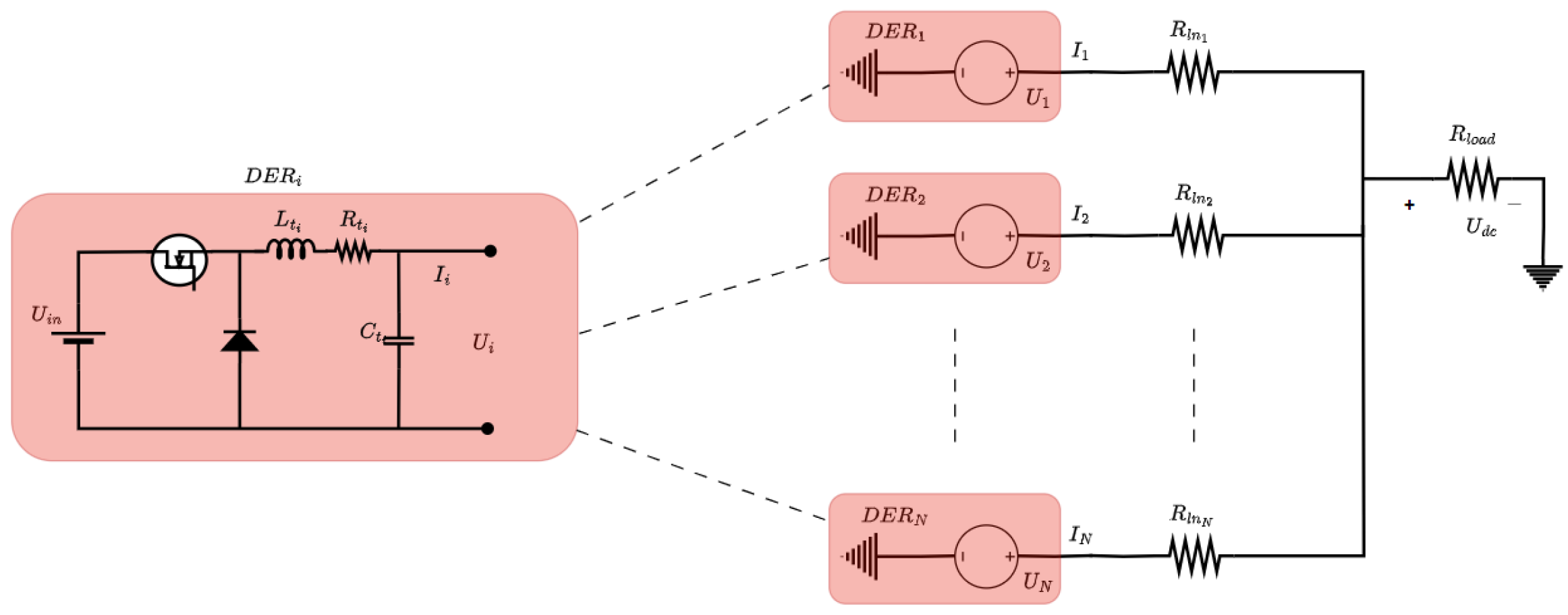
When multiple DC converters are interconnected parallelly to a shared DC bus, the droop control functions as the primary control level utilized to synchronize these converters. The main goal of droop control is to maintain a predetermined load or current distribution ratio among these interconnected converters. Taking into account the direct current microgrid configuration depicted in Figure 5, the DC bus voltage can be formulated as:
U d c = U i r I i R l n i ,
where I i , U i r , and R l n i represent current output, voltage reference, and line resistance for the ith distributed energy source converter, respectively. The reference voltage, established through the utilization of a droop controller to enable current sharing, is presented as:
U i r = U r I i R d i ,
where R d i and U r denote the resistance of the droop and the nominal DC voltage for the ith distributed energy source converter, respectively. Examining (6) and (7) for converters in D E R i and D E R j , which are interconnected to the shared DC bus, we can derive the droop relationship as:
( R l n i + R d i ) I i = ( R l n j + R d j ) I j ,
and
I i I j = R l n j + R d j R l n i + R d i R d j R d i ,
assuming the resistance of the droop is configured greater than the resistance of the line.
Analyzing the stability of the primary control for the converter involves deriving the state-space (SS) model using the schematics depicted in Figure 4, with the state variables highlighted in red. x 1 i , x 2 i , x 3 i , and x 4 i denote the inductor current, output capacitor voltage, voltage control integrator output, and current control integrator output of the ith converter, respectively. The dynamic expression representing the reference input of the voltage control integrator, contingent on the operation of the droop controller for the ith DER converter, can be formulated as:
x ˙ 3 i = U r R d i x 1 i x 2 i .
Similarly, the dynamic expression for the current control integrator input reference from the voltage PI control can be expressed as:
x ˙ 4 i = K v i i x 3 i + K v p i x ˙ 3 i x 1 i = K v i i x 3 i + K v p i ( U r R d i x 1 i x 2 i ) x 1 i = ( 1 K v p i R d i ) x 1 i K v p i x 2 i + K v i i x 3 i + K v p i U r ,
where K v i i and K v p i denote the voltage control integral and proportional gains for the ith DER converter, respectively. To finalize the SS model for the converter operating within the direct current MG, the equations of the DC voltage and current output are derived from (1) and (2) as follows:
x ˙ 1 i = 1 L t i ( ( K i p i K i p i K v p i R d i ) x 1 i K i p i K v p i x 2 i + K v i i K i p i x 3 i + K i i i x 4 i + K i p i K v p i U r ) ,
x ˙ 2 i = 1 C t i x 1 i 1 R l o a d C t i x 2 i ,
where K i i i and K i p i denote the current control integral and proportional gains for the ith DER converter, respectively. Utilizing (10) to (13), the SS model for the ith DER, incorporating primary control in the context of a direct current MG application, can be represented in a standard SS format as follows:
X ˙ m i = A m i X m i + B m i U Y m i = C m i X m i ,
where C m i , and B m i denote the output and input matrices expressed in (14), respectively. A m i and X m i = [ x 1 i , x 2 i , x 3 i , x 4 i ] T denote the state matrix expressed in (16) and state vector, respectively. Y m i represents the output vector and U = [ U r ] denotes the input vector.
B m i = 0 K i p i K v p i L t i 1 K v p i T , C m i = 1 0 0 0 0 1 0 0
A m i = 1 C t i 1 R l o a d C t i 0 0 ( K i p i K i p i K v p i R d i ) L t i K i p i K v p i L t i K v i i K i p i L t i K i i i L t i R d i 1 0 0 ( 1 K v p i R d i ) K v p i K v i i 0 .
Upon scrutiny of (6), it is apparent that a deviation in the bus voltage ( U d c ) will consistently arise when the current surpasses zero. From Equation (7), it is also evident that increasing the resistance of the droop ( R d ) significantly to improve accurate current distribution leads to a deviation in DC voltage. Therefore, the primary control alone cannot achieve accurate current distribution among multiple DERs without causing a significant bus voltage deviation. Implementing secondary control becomes crucial to achieve both voltage restoration and precise current sharing simultaneously.

3. Distributed Secondary Control Technique

Addressing the previously mentioned limitation of primary control, a novel secondary distributed control approach is designed. This aims to facilitate simultaneous voltage regulation and current sharing within an islanded DC microgrid, where multiple DERs are interconnected in parallel to a common DC bus. Every DER converter within the microgrid is equipped with its own individual localized (primary) control. These operate independently without communication with other local controls within the MG. The deviation induced by the droop control is offset by the new reference signal produced by the secondary control. The secondary distributed control technique incorporates a communication network to address the inherent single-point failure drawback associated with centralized secondary control. Under this technique, each distributed energy source, equipped with its own secondary control loop, has the ability to share information with other secondary controls within the MG through the network. In this study, the proposed secondary distributed control technique aims to maintain the bus voltage at its rated level while simultaneously ensuring a fair distribution of current.

3.1. Communication Graph

The communication network within the MG, involving n converters, can be depicted as an undirected graph symbolized as G . In this graph, communication links are depicted as edges, while converters are treated as nodes. An undirected graph is defined by edge sets, denoted as E V n × V n , and node collections, represented as V n = { v 1 , v 2 , . . . , v n } . If there exists an edge ( v i , v j ) such that ( v i , v j ) E n , it indicates that node i can share information with node j, and in this context, node j is referred to as a near-neighbour of node i. The collection of neighbours for node i is depicted by N i . The graph’s adjacency matrix is described as A = [ a i j ] R n × n ; with ( v i , v j ) E n , a i j > 0 and ( v i , v j ) E n , a i j = 0 . The in-degree matrix of the undirected graph, denoted as D = [ d i j ] R n × n , follows the conditions d i j = j N i a i j , along with d i j = 0 when j i . The Laplacian matrix, denoted as L = [ l i j ] R n × n , is derived as L = D A . If the condition a i j = a j i holds true for all j and i within the graph, then the associated L is considered balanced, assuming an information exchange occurs between the vertices i and j. Consensus regarding a variable b is considered attained when b i ( t ) b j ( t ) 0 , and this consensus is established in accordance with the first-order consensus equation illustrated in (17) [47].
b ˙ i = j = 1 n a i j ( b i b j ) i = 1 , 2 , , n ,
A sequence of edges connecting one node to another is called a directed path. An undirected graph is deemed connected if consistently at least one directed path connects any pair of random nodes within it. When a graph possesses a directed spanning tree, it implies the existence of at least one root node capable of reaching all other nodes through directed paths, and then (17) meets the condition: lim t | b i ( t ) b j ( t ) | = 0 . Therefore, the near-neighbour/reduced communication topology, illustrated in Figure 6, is utilized in this research.

3.2. Control Objectives

The foremost objective of the newly introduced secondary distributed control, shown in Figure 7, is to regulate the bus DC voltage at its designated nominal value. The bus voltage variation resulting from the action of the droop controller is inferred from (6) and (7) to obtain (18).
Δ U d c = U r U d c = ( R l n i + R d i ) I i .
Therefore, the control objective for voltage restoration can be formulated as follows:
lim t Δ U d c ( t ) = 0 o r lim t U d c = U r .
Ensuring equitable current distribution, which ultimately results in balanced power allocation among the parallelly connected DERs, is the second control goal of the newly introduced secondary distributed control. As previously noted, the current distribution mathematical expression in (9) results in the deviation of the bus voltage from its nominal value. Thus, in the case of the ith DER, the control objective for current sharing is expressed as:
lim t Δ I i ( t ) = 0 ,
where
Δ I i ( t ) = j N , j i a i j I i ( t ) c i 1 N 1 I j ( t ) c j ,
where N represents the number of distributed energy sources operating in the microgrid and c i denotes the ratio of the current distribution for the ith DER. The adjacency matrix entries, depicted as a i j , are allocated a zero value, signifying a communication link absence or a disconnection, or are configured to one, indicating a connection between the neighbouring DERs.

3.3. Proposed Control Design

In line with the defined control objective, the secondary distributed control is tailored to counteract the voltage deviation the droop control induces, as depicted in Figure 7. Therefore, the bus voltage due to the influence of the secondary control signal introduced into the system can be formulated using (6) as follows:
U d c = U r R l n i + R d i I i + H i ( t ) ,
where Q i denotes the signal input originating from the secondary control proposed for the ith DER, which is formulated through the utilization of a straightforward feedback control law expressed as:
H i ( t ) = φ i · e i t ( t ) ,
where e i t represents the integral combination of the deviations or errors, which is given by:
e i t ( t ) = α i Δ U d c ( t ) d t + β i Δ I i ( t ) d t ,
where φ , β , and α denote the proposed secondary control parameters.
To evaluate the effect of the proposed secondary control on the stable operation of the direct current MG, we establish the dynamic equations governing the control system. The error input for the voltage reference, as described in (9), is altered by the inclusion of the secondary control to become:
x ˙ 3 i = U r R d i x 1 i x 2 i + H i .
Therefore, the dynamic equation for the newly introduced secondary distributed control is formulated as follows:
H ˙ i = φ β x 1 i β N 1 j N x 1 j α x 2 i + α U r .
Employing (11)–(13), along with (25) and (26), we can formulate the SS model for the ith DER, which incorporates the secondary control, as follows:
X ˙ s m i = A s m i X s m i + B s m i U Y s m i = C s m i X s m i ,
where C s m i , and B s m i denote the output and input matrices expressed in (28), respectively. A s m i and X s m i = [ x 1 i , x 2 i , x 3 i , x 4 i , H i ] T denote the state matrix expressed in (29) and state vector, respectively. Y s m i represents the output vector and U = [ U r ] denotes the input vector.
B s m i = 0 K i p i K v p i L t i 1 K v p i φ α T , C s m i = 1 0 0 0 0 0 1 0 0 0
A s m i = 1 C t i 1 R l o a d C t i 0 0 0 ( K i p i K i p i K v p i R d i ) L t i K i p i K v p i L t i K v i i K i p i L t i K i i i L t i 0 R d i 1 0 0 1 ( 1 K v p i R d i ) K v p i K v i i 0 0 φ α φ β 0 0 0 .
Designing the parameters of the proposed secondary distributed control to attain the control objectives of both voltage restoration and current distribution is an intricate and time-intensive process. This complexity arises from the fact that these parameters influence the DER’s response and have implications for the stability of the direct current MG. Through basic analysis, it can be observed that selecting a high value for α leads to rapid convergence toward achieving the control objective for bus voltage restoration while selecting a high value for β facilitates faster convergence toward achieving the control objective for current distribution. Conventionally, α is typically selected to be less than β . This choice is because the voltage recovery objective pertains to a global target for the DC bus, while the current distribution objective involves achieving consensus among all DERs. To simplify the tuning process, augment the flexibility, and improve the adaptive ability of the secondary distributed control, we propose a novel and improved tuning technique for selecting the suitable value of φ . This parameter is crucial as it acts as a weighting factor governing the balance between the current distribution and voltage restoration control objectives.

4. Distributed Secondary Control Enhanced Tuning Approach

This section introduces an innovative tuning approach for the proposed secondary control weighting parameter, φ . The tuning technique is the hybrid FFA–PSO algorithm, which combines the swift computational abilities of PSO with the robustness of the FFA, leading to an equilibrium between exploitation and exploration.

4.1. Particle Swarm Optimization (PSO)

The PSO method is a population-based meta-heuristic algorithm initially conceived by Eberhart and Kennedy [35]. This approach derives its principles from the collective behaviour observed in living organisms, akin to a flock of birds or a school of fish. Particles move around the search space in PSO, and each time they iterate, all of the particles in the population coordinate their motion according to two parameters.
Particles traverse the search space in PSO, and each time they iterate, all particles within the population coordinate their motion according to two criteria: its personal best location (referred to as S b e s t , representing the local best solution) and the best value of the entire swarm (referred to as J b e s t , depicting the global best location).
The simplicity of PSO presents a notable advantage over alternative optimization methods. Its requirement for minimal parameter adjustment contributes to its widespread adoption across diverse applications. The motion of the particles within the swarm is mathematically expressed through (30) and (31) that update both velocity and position, respectively. These equations govern the movement dynamics.
V i ( n + 1 ) = w V i ( n ) + c 1 k 1 ( S b e s t i ( n ) Y i ( n ) ) + c 2 k 2 ( J b e s t ( n ) Y i ( n ) ) ,
Y i ( n + 1 ) = Y i ( n ) + V i ( n + 1 ) .
where c 2 , c 1 , and w represent the acceleration coefficients and inertia weight, while k 1 and k 2 stand for two randomly generated values within the range of [0, 1].

4.2. Firefly Optimization Algorithm (FFA)

The FFA is an optimization algorithm inspired by the flashing behaviour of fireflies. Proposed by Xin-She Yang [34], this algorithm mimics the flashing patterns of fireflies to solve optimization problems. According to the inverse square law, the intensity of light emanating from a source diminishes as the distance from that source increases [43]. Additionally, the medium through which light travels from its source to its destination also contributes to the absorption of the light.
Fireflies, tiny insects with the ability to emit light, use this luminescence to attract potential mates or prey, signalling their presence through rhythmic, intermittent flashes of light. The attraction of fireflies based on light intensity, denoted as I, diminishes as the distance Q d increases. As a result, the visibility of most fireflies is limited to distances of just a few hundred meters. In implementing this algorithm, the fitness function is formulated by considering the fluorescent light patterns exhibited by fireflies. In a simplified context, the attractiveness of a firefly based on light intensity is determined by its brightness, which is linked to the fitness function. The light intensity, In accordance with the inverse square law, at a distance Q d from a light source I s is determined by [44]:
I ( Q d ) = I s / Q d 2 .
Within an environment, light undergoes absorption governed by a constant light absorption coefficient γ [ 0 , ) . Consequently, this phenomenon can be represented in Gaussian form through (33).
η ( Q d ) = η o · e γ Q d 2 .
where η o signifies the attractiveness when Q d equals zero. The estimation of the distance between any two fireflies is determined using a distance formula:
Q d i j = y i y j = k = 1 n ( y i , k y j , k ) 2
The movement of firefly i towards the brighter firefly j is computed with:
y i = y i + η o e γ Q d i , j 2 ( y i y j ) + σ ϵ i
The first component in (35) represents the present location of a firefly, the second term is utilized to ascertain the attractiveness ( η ) of a firefly towards neighbouring attractive fireflies, and the third term signifies the stochastic movement of a firefly (random element).
y i = y i + σ ( r a n d 1 / 2 )
If firefly i does not have a brighter counterpart j, it proceeds to embark on a random walk as detailed in (36), seeking the optimal candidate. Here, the coefficient σ represents a randomization variable, and within the interval (0, 1), a uniformly distributed random number is indicated by r a n d .

4.3. Proposed Hybrid FFA–PSO for Distributed Secondary Control

The hybridization of the FFA–PSO techniques was proposed by Aydilek Ibrahim [34]. A hybrid equilibrium is established to balance exploitation (global optima) and exploration (local optima), leveraging the strengths and benefits of both PSO and the FFA methodologies [43]. The firefly algorithm does not incorporate terms for velocity (V) or personal best position ( S b e s t ). During a global search, the PSO approach showcases rapid convergence, specifically emphasizing exploration. Furthermore, the FFA proves advantageous in conducting local region searches or excels in achieving precise exploitation. Figure 8 illustrates the flowchart depicting the hybrid FFA–PSO approach.
Firstly, input parameters are introduced. Subsequently, these parameters are sequentially utilized by both optimization methods. Following this, constant swarm vectors are initialized within the search space, along with defining velocity ranges. Individual best ( S b e s t ) and global best ( J b e s t ) swarms are computed and assigned accordingly. The computed values are compared during the ultimate iteration. Additionally, the current location is preserved, after which new position and velocity are computed according to the following [34]:
f ( i , n ) = t r u e , i f f i t n e s s ( p a r t i c l e i n ) J b e s t n 1 f a l s e , i f f i t n e s s ( p a r t i c l e i n ) > J b e s t n 1
Y i ( n + 1 ) = Y i ( n ) + η o e γ Q d i j 2 ( Y i ( n ) J b e s t n 1 ) + σ ϵ i
V i ( n + 1 ) = Y i ( n + 1 ) Y i t e m p
Therefore, when a particle exhibits an equivalent or superior fitness value compared to the preceding global best, it triggers the commencement of a local search, where the particle is managed by an emulative FFA, according to (38) and (39). Conversely, the particle is directed to be managed by PSO, where PSO proceeds with its customary operations for this particle following (30) and (31). During the subsequent comparison phase, evaluations of fitness functions and constraints within specified ranges are verified for all particles and fireflies. Upon reaching the maximum iteration limit, the hybrid algorithm will cease execution, and the output of the proposed hybrid algorithm will be the best J b e s t , along with its corresponding fitness value. The location of the particle with this J b e s t , which is the optimized parameter, φ , is extracted.
In an effort to improve the performance of the DC MG, particularly in meeting voltage and current control objectives, this article presents a control strategy. This strategy optimizes the distributed secondary controller’s newly introduced parameter, φ , based on the fitness function in (40). Within the existing literature, various types of fitness functions have been employed for optimization. These include the integral square error (ISE), integral time square error (ITSE), integral absolute error (IAE), and integral time absolute error (ITAE). In this article, the ITAE objective function has been selected due to its ability to yield faster rising times, reduced overshoots, and shorter settling times compared to other objective functions commonly found in the literature [48] while adhering to the constraints specified in (41). Furthermore, the control objectives of the newly introduced secondary distributed control are accomplished by guaranteeing that the voltage deviation and current sharing error converge asymptotically to zero. To achieve optimal control tuning, the selected fitness function can be formulated as:
Z = 0 T t · ( Δ I i + Δ U d c ) d t
Incorporated within the hybrid FFA–PSO Matlab code are the maximum and minimum values of the secondary control parameters, φ , enabling the determination of the optimal values according to the system requirements, as demonstrated below:
φ m i n φ φ m a x
where φ m a x and φ m i n are the maximum and minimum values of the weighting coefficient introduced in the secondary distributed control of the direct current MG, as illustrated in Figure 7. Limiting this value will empower the hybrid FFA–PSO algorithm to explore suitable values for φ within a predefined range in alignment with the system requirements. The pseudocode outlining the proposed hybrid FFA–PSO algorithm is outlined in Algorithm 1. The inertia weight (w) parameter aids in balancing exploitation and exploration within the hybrid FFA–PSO, according to (42) [43]. This inertia weight diminishes linearly in accordance with the number of iterations completed.
w = w i ( w i w f ) · n i t e r a t i o n M a x .
where n, w i , and w f represent the present iteration, initial weight, and final weight, respectively. The minimum and maximum velocities of a particle ( V m i n , V m a x ) are utilized to confine the subsequent distance in a particular direction. These limits are randomly generated within the velocity range at the outset of the proposed algorithm.
Algorithm 1 Proposed Hybrid FFA–PSO Algorithm Implementation
  • Require: initialize input parameters. Assign:
  • w f , w i : Final and initial value of inertia weights.
  • c 1 , c 2 : Acceleration coefficients.
  • Y: Present particle location
  • Y m a x , Y m i n : Maximum and minimum range of search limit.
  • V: Present particle velocity
  • V m a x , V m i n : Maximum and minimum limit of velocities.
  • Pop: Size of population (swarm)
  • dim: Particle dimension
  • n: Present iteration number
  • i t e r a t i o n m a x : Maximum iteration number
  •  
  • Initialize the locations Y[Pop][dim] randomly within the search range ( Y m i n , Y m a x )
  • Initialize the velocity V[Pop][dim] randomly within the velocity range ( V m i n , V m a x )
  • Compute S b e s t and J b e s t
  • Evaluate the fitness value using (40)
  • while  i t e r a t i o n m a x do
  •     for i=1 to Pop do
  •         if particle fitness value improves in the previous iteration in line with (37) then
  •            Store present particle location/position ( Y i (n)) in temp variable ( Y i t e m p )
  •            Update particle location and velocity according to (38) and (39), respectively
  •         else
  •            update w according to (42)
  •            Update particle velocity and location according to (30) and (31), respectively
  •         end if
  •         Check the range limits of the particle location and velocity
  •         Compute new fitness value for particle
  •         if new fitness value of particle < S b e s t  then
  •            Update the S b e s t value
  •         end if
  •         if new fitness value of particle < J b e s t  then
  •            Update the J b e s t value
  •         end if
  •     end for
  • end while
Rank and provide the most optimal solution.

5. Results and Discussion

This section showcases the efficacy of the newly implemented secondary distributed control system across diverse simulation scenarios. A state-space (SS) model for a DC microgrid comprising three distributed energy sources was designed using MATLAB/Simulink® by leveraging on the mathematical framework of the buck converter and control strategies governing the operation of a single DER as detailed in Section 2 and Section 3. Stability analyses were then conducted using eigenvalue analysis on the MG model, which incorporates both secondary and primary controls. Subsequently, the ability of the secondary distributed control to achieve the control objectives related to current distribution and voltage restoration is examined by employing the designed direct current MG SS model. Table 1 [46] details the parameters utilized for the direct current MG state-space model.

5.1. Stability Analysis

Analysing the state matrix (A matrix) eigenvalues is necessary to evaluate the stability of the system. If all the eigenvalues of the A matrix display negative real components, the system is considered asymptotically stable. Practically, this implies that the system will return to its equilibrium state after experiencing a small-signal disturbance. In this study, we developed the state matrix, A m , for the direct current MG equipped solely with primary control through (15), while the state matrix, A s m , with the secondary control proposed was formulated using (28). Table 2 presents the direct current MG eigenvalues with the operations of the secondary and primary controls. Under primary control, the eigenvalues of the system contain positive real components ( λ 2 and λ 3 ) and this makes the direct current MG unstable. Nonetheless, upon the integration of a more advanced control layer, specifically the secondary control, the system’s stability was enhanced, resulting in all eigenvalues possessing negative real components. The presence of complex parts in the eigenvalues implies that the system will experience oscillations during a small-signal perturbation before ultimately returning to its equilibrium state.

5.2. Realization of Control Objectives

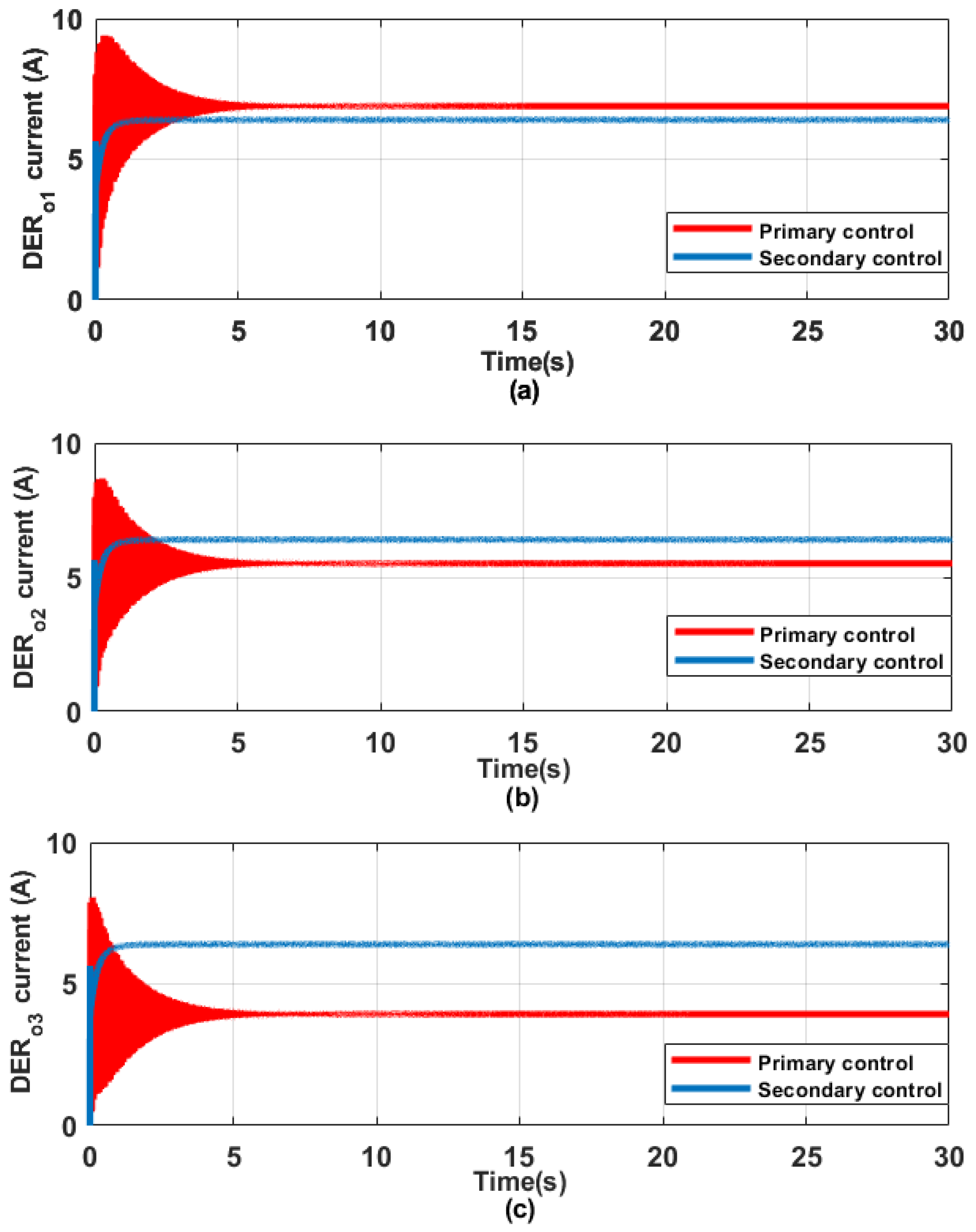
The effectiveness of the proposed secondary control in attaining equitable voltage restoration and current sharing objectives employing the SS formulation of the DC MG is investigated in this scenario. The direct current MG is designed to function at a rated voltage of 48 V, and the distributed energy sources are configured to evenly distribute the load. The result obtained for the microgrid bus voltage is illustrated in Figure 9. An approximate bus voltage deviation, Δ U d c , of 8 V is noticed when the primary control alone (indicated by the green plot) of each DER is in operation. Nevertheless, upon activating the secondary control, the bus voltage is effectively regulated to its rated value ( U d c = 48 V) with considerably reduced oscillation in comparison to the system controlled solely by the primary control. Similarly, Figure 10 illustrates the current outputs of the DERs within the MG. It is noticeable that achieving uniform current distribution among the converters proves challenging ( D E R o 3 = 3.7 A, D E R o 2 = 5.3 A, D E R o 1 = 6.5 A), with the primary control alone being operational in each DER, as indicated by the green plots in Figure 10a–c. However, the DERs successfully attained uniform current distribution throughout the simulation period ( D E R o 3 = D E R o 2 = D E R o 1 = 6 A) upon enabling the secondary distributed control in each DER, as depicted by the red plots in Figure 10a–c. It is deduced that the secondary distributed control possesses the ability to effectively realize the control goals outlined in (18) and (19) for direct current MG under study.

5.3. Real-Time Experimental Simulation Validation

In this section, the robustness and efficacy of the proposed secondary distributed control system are showcased in real time across diverse practical scenarios. These include scenarios involving load variations and communication delays, providing insights into its real-world applicability and performance. In the real-time configuration, four distributed energy sources providing power to both resistive and constant power loads are modelled. Each individual DER is equipped with a converter that incorporates local control. Additionally, a secondary control loop has been devised for each DER, facilitating interaction with neighbouring DERs through communication links, thus establishing the distributivity features of the control technique. The real-world scenarios were effectively replicated by developing a detailed DC microgrid model within a real-time system, utilizing the Speedgoat real-time simulator. The Speedgoat target machine is a sophisticated real-time system explicitly tailored for real-time testing, purpose-built to seamlessly integrate with the Simulink and Simulink Real-Time toolboxes offered by MathWorks. It finds application in rapid control prototyping, hardware-in-the-loop simulations for testing systems, and the execution of control algorithms created using MATLAB/Simulink® R2022b software. The Speedgoat (Bern, Switzerland) simulator has an Intel 4.2GHz core i7-7700K quad-core CPU. Matlab/Simulink® was employed to develop and assess the DC microgrid model and the control algorithms within a simulated environment. HDL Coder and Simulink Real-Time perform automatic code generation from the Simulink models of the direct current MG and subsequently deploy these codes to the Speedgoat real-time target machine for execution. A sampling frequency of 20 kHz was utilized, while Table 3 provides the detailed system parameters used. Figure 11 illustrates the test system schematic.

5.3.1. Voltage Restoration and Current Distribution Test

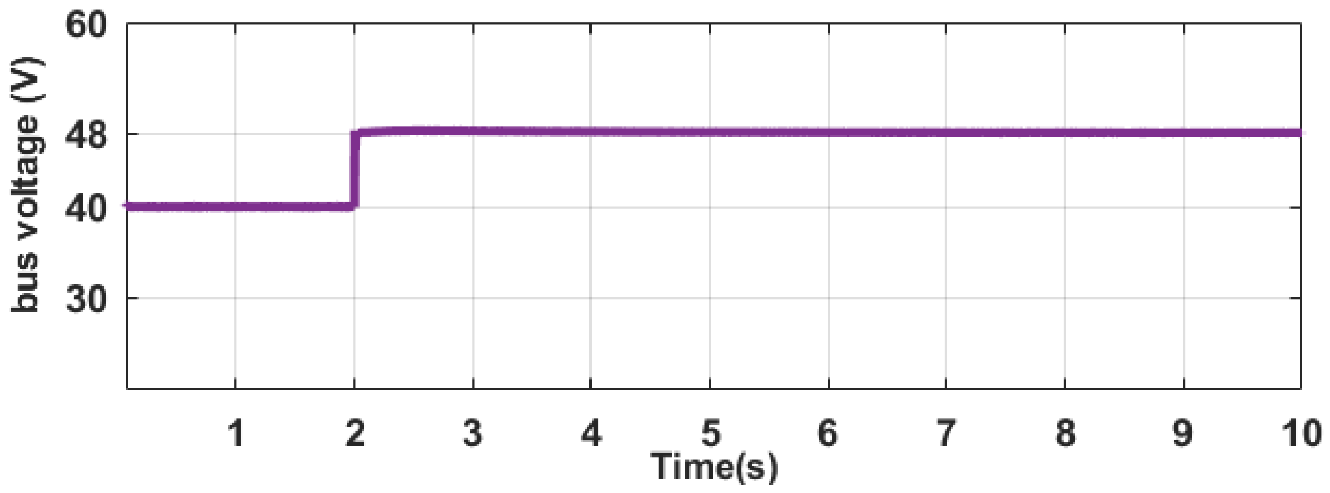
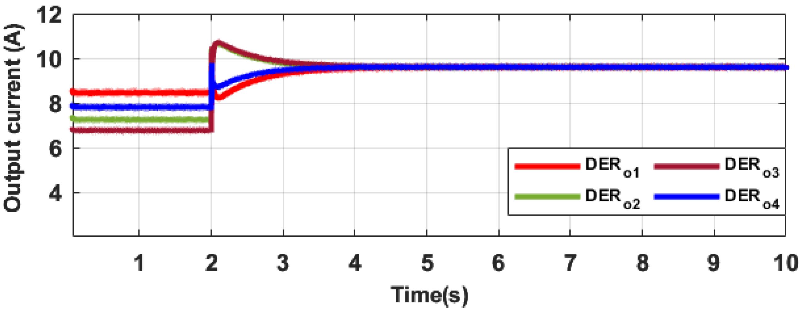
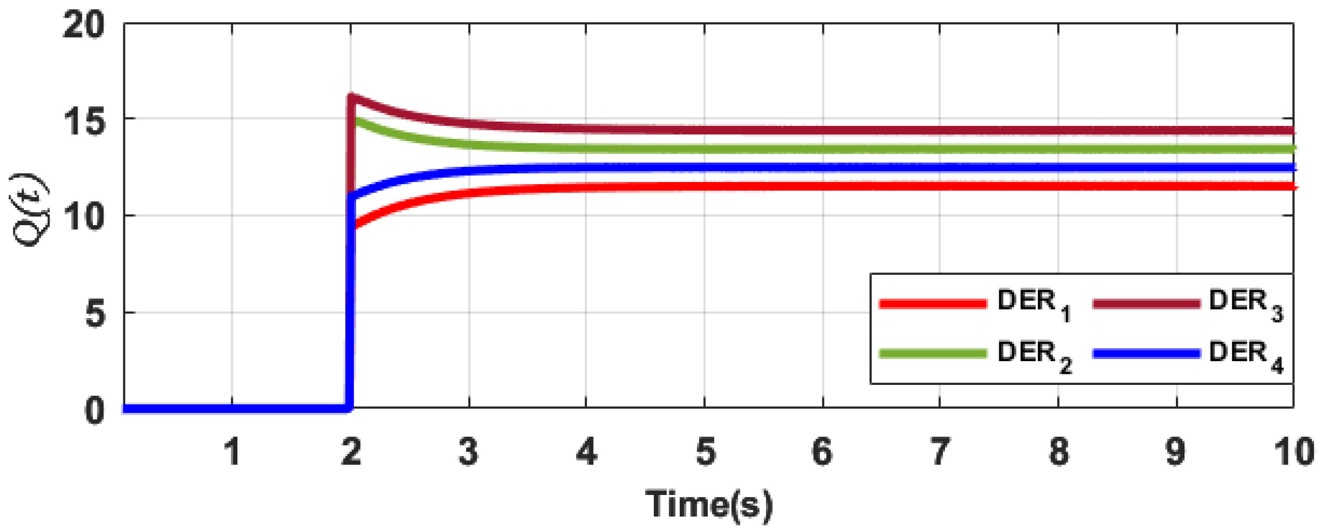
In this scenario, tests were conducted to evaluate both equitable current distribution and voltage restoration. The overarching objective is to maintain the direct current microgrid bus voltage at the rated voltage level, serving as the global objective, while the secondary distributed control also facilitates fair current allocation, aligning with the consensus objective for all DERs within the MG. The simulation is segmented into two stages. During the first stage, t [ 0 , 2 ) , solely the primary droop control within each DER is operational, with R L 1 , R L 2 , and R L 3 loads connected. The distributed control proposed is subsequently activated in all the DERs during the last stage t ( 2 , 10 ] . Figure 12, Figure 13 and Figure 14 illustrate the outcomes of the simulation. In Figure 12, the bus voltage profile during the entire simulation duration is observed. In the first stage, the bus voltage is recorded at 38 V, resulting in a 10 V deviation from the nominal value. Nevertheless, upon activating the proposed distributed control in stage two, this deviation is rectified within 0.2 s, having a 2.5% overshoot, and the bus voltage is stabilized to its designated rating of 48 V. Figure 13 presents the current outputs for the DERs. During stage one, which involves primary control, it is noticeable that the current outputs exhibit disparities ( D E R o 4 = 7.5 A, D E R o 3 = 6.6 A, D E R o 2 = 7.1 A, D E R o 1 = 8.2 A) even though they are subject to an equal current distribution ratio (1:1:1:1). In stage two, the current outputs converge to a uniform value ( D E R o 4 = D E R o 3 = D E R o 2 = D E R o 1 = 9.4 A) within 1.4 s after the proposed secondary control is enabled. At t = 2 s, the attainment of control objectives becomes evident upon activating the secondary distributed control proposed within each DER, as illustrated in Figure 14. In this context, the corresponding secondary control signals are produced for individual DERs, facilitating interaction with neighbouring DERs to accomplish both precise consensus in current distribution and global bus voltage restoration.

5.3.2. Proposed Secondary Control Performance under Load Variations

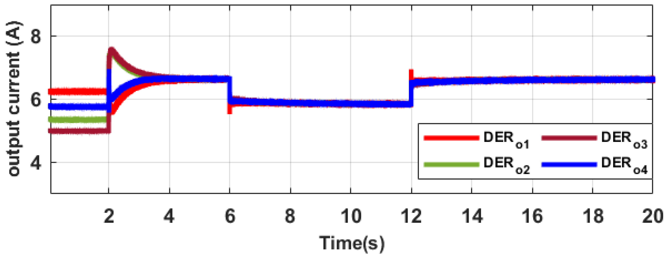
Another practical scenario is explored in real time in this section. Employing the identical communication topology as in the prior section, power flow alterations are assessed to explore the distributed characteristics of the secondary control proposed. An extra load R C P L is incorporated into the DC bus. The simulation time frame for this scenario spans 20 s, with the following operational stages: during t [ 0 , 2 ) , only the primary droop control within individual DERs is operational, coupled with the resistive loads R L 1 , R L 2 , and R L 3 and a constant power load (CPL), R C P L ; then, at t = 2 s during the t ( 2 , 6 ) , the secondary controls in each DER are initiated. Subsequently, at t = 6 s during the t ( 6 , 12 ) , R C P L is disconnected from the bus, and during the t ( 12 , 20 ] , the load is reconnected to the bus at t = 12 s. The results obtained from the test scenario are presented in Figure 15, Figure 16 and Figure 17. Upon examining the bus voltage depicted in Figure 15, it becomes evident that there is an abrupt surge in bus voltage at the disconnection of the load. Nonetheless, this transient is rapidly controlled within 0.7 s, restoring the bus voltage to its steady-state value with a 6.1 % overshoot, thereby ensuring the stability of the MG. Likewise, reconnecting the load at t = 12 s results in a decline in the bus voltage. However, this decrease is swiftly rectified within 0.6 s, having a 4.16% undershoot, and returning the voltage to its nominal value by the voltage control mechanism of the secondary control proposed in this article. Figure 16 demonstrates that balanced current distribution is accomplished at the activation of the secondary control ( t = 2 s). The DERs experience a drop in current outputs from 6.5 A to 5.6 A, with a short transient having a slight 5.61% undershoot in current output from DER 1 when the load is disconnected at t = 6 s. However, they seamlessly attain real-time consensus operation within 0.4 s without disrupting the microgrid’s communication protocol. Moreover, reconnecting the load at t = 12 s does not disrupt the ability of the DERs to maintain their balanced current distribution characteristics. The DERs experience a current rise from 5.6 A to 6.5 A, with a short transient exhibiting a peak current overshoot of 4.77% with DER 1 and attaining consensus within 0.4 s. As illustrated in Figure 17, the secondary control signals swiftly and efficiently reacted to attain the control objectives at the necessary moments. It is deduced that the secondary control introduced in this research can effectively maintain the distributed properties even when there are variations in power flow characteristics within the MG, all without disrupting the microgrid’s communication topology. Similar outcomes were also obtained in previous research endeavours [27,28,45], where they evaluated the effectiveness of their proposed technique by subjecting it to different changes in CPL and resistive loads.

5.3.3. Proposed Secondary Control Performance under Communication Time Delays

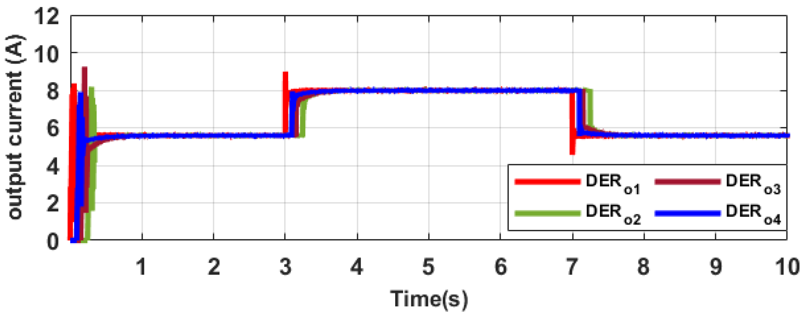
Communication links are pivotal in enabling the functionality of secondary distributed controls within the microgrid. They facilitate interaction and data exchange, which is crucial for achieving the designated control objectives. Consequently, it becomes essential to evaluate how communication network delays may affect the performance of the secondary control introduced in this research. Through the sparse communication topology explained in Section 3.1, different time delays among the DER secondary controllers were investigated. The links a 12 , a 13 , and a 34 are set to 100 ms, 250 ms, and 150 ms, respectively. Three phases were considered in the real-time simulation, spanning a total duration of 10 s. During the first phase, which covers the time span t [ 0 , 3 ) , both the DER primary droop and secondary controllers are initiated at t = 0 s, coupled with the connection of loads R L 1 , R L 3 , and R C P L . In the second phase, occurring within the time span t ( 3 , 7 ) , an extra R L 2 load is integrated at t = 3 s, and the disconnection of the load occurs at t = 7 s during the final phase, t ( 7 , 10 ] . The results obtained from the test scenario are presented in Figure 18, Figure 19 and Figure 20. Based on the observation in Figure 18, it is clear that during the first phase, the start times of the output current from the DERs display variability. This disparity emerges as a result of the varying time delays within the microgrid’s communication protocol. Nonetheless, the secondary distributed control introduced in this study guarantees the achievement of consensus in the current distribution within a swift operational timeframe of less than 0.6 s. Likewise, when the load is integrated during the second phase and disconnected during the last phase, the current output of individual DERs adjusts appropriately in both scenarios to match the evolving power requirements. The current output responses mirror the impact of time delay, yet the collective current demand is evenly distributed among the DERs.
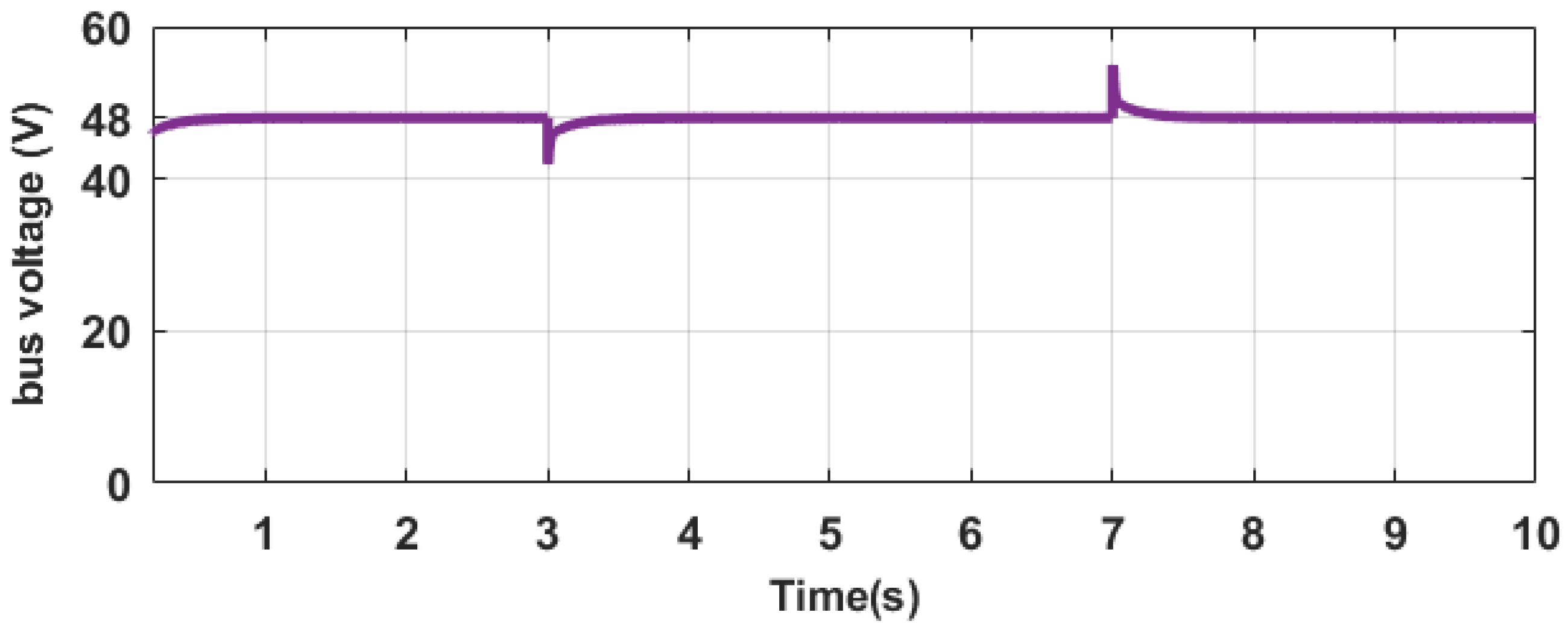
Furthermore, Figure 19 displays the bus voltage in this particular scenario. Contrasting with the response of the current output, the influence of time delay on the bus voltage is not evident. This distinction arises because the voltage regulation objective is global, requiring control intervention from at least one functioning DER, while the current sharing objective is consensus based, demanding control participation from all functioning DERs within the microgrid. The secondary control signals are illustrated in Figure 20, showcasing the control actions implemented by the proposed secondary distributed control. It is evident that each secondary control reacts to accomplish the control objectives, guaranteeing both the stabilization of bus voltage at its nominal level and proper allocation of load current among the DERs. Hence, it can be inferred that the proposed distributed control offers advantages by aiding system restoration, even when faced with communication latency. Similar outcomes were attained in prior research [27,45], where the effects of communication delays were similarly assessed.

5.4. Comparison with other Distributed Secondary Control Approach

This section presents a response time comparison assessment of the proposed secondary distributed control in attaining the control objectives, as observed in Section 5.3.1, with other secondary distributed control schemes introduced in prior research. The chosen control techniques share identical control objectives, which include voltage restoration and current sharing, albeit they differ in the design of their control parameters: consensus secondary control (H4) [29], supervisory secondary control (H3) [28], model predictive secondary control (H2) [49], and conventional secondary control (H1), which involves a trial-and-error tuning technique of the control parameters. Table 4 provides a summary of the comparative results between the proposed control technique and alternative approaches. Examining the outcomes presented in Table 4, it is observed that the proposed technique, in comparison to H4, demonstrates a 93% reduction in response time for bus voltage restoration and a 59% decrease in response time for precise current distribution. When compared to H3, the proposed technique showcases an 88% reduction in response time for the rapid restoration of the bus voltage to its designated rating, as well as a 30% decrease in response time for efficient current sharing. In contrast to H2, the proposed distributed control demonstrates an 85% reduction in response time for the restoration of bus voltage to its rated value, along with a 7% decrease in response time to achieve efficient current distribution. Furthermore, in comparison to the conventional secondary control approach, the proposed technique outperforms it with a 90% reduction in response time for quickly restoring the voltage to its designated rating, as well as a 50% decrease in response time for achieving balanced current sharing. It is important to note that the control objective for voltage restoration is accomplished more swiftly than the current distribution objective. This difference in response time arises because the current distribution objective necessitates consensus among the distributed energy sources, involving communication between them, while the voltage restoration objective places a comparatively lighter communication burden.

6. Conclusions

This article presents a novel secondary distributed control technique specifically engineered to enable current distribution among numerous distributed energy sources, concurrently ensuring voltage restoration within a direct current microgrid. The proposed control technique relies on an integral control approach, with its design coefficients determined through the application of a hybrid FFA–PSO algorithm. Minimizing the current distribution and the voltage deviation error within the MG is the objective function of the hybrid FFA–PSO algorithm. Due to its tuning process, this control technique exhibits robustness and provides advantages through its adaptability. The evaluation of the designed control involves assessing its performance using both the physical and state-space models of the DC MG. Additionally, eigenvalue analysis is used to assess the stability of the proposed control. Real-time experiments are carried out using the Speedgoat simulator to validate the robustness and effectiveness of the proposed secondary control in achieving the microgrid’s control objectives. The outcomes indicate that the proposed distributed control system can attain precise current distribution and voltage restoration in an islanded DC microgrid, exhibiting a 90% reduction in response time for recovering the bus voltage to its rated value, along with a 50% decrease in response time for realizing optimal current distribution in comparison to the conventional control system. Therefore, implementing the proposed secondary distributed control in real-world DC microgrids offers an effective solution for addressing challenges related to voltage regulation and achieving balanced current distribution. Future research endeavours might encompass exploring diverse converter configurations and integrating hybrid distributed energy sources. Consideration can also be given to the responsiveness of the controller to fluctuations in the energy sources and their intermittency. In addition, more evolutionary metaheuristic algorithms can also be investigated to improve the response of the controller.

Author Contributions

Conceptualization, O.L., A.A. and A.S.; methodology, A.A., O.L. and A.S.; software, A.S., O.L. and A.A.; validation, A.S., A.G., A.A. and L.J.; formal analysis, A.S., O.L., A.G. and A.A.; resources, L.J., A.G. and A.S.; writing—original draft preparation, A.A., O.L. and A.S.; writing—review and editing, O.L., A.S. and L.J.; visualization, A.S. and O.L.; supervision, A.S. and L.J.; project administration, A.S.; funding acquisition, A.S., A.G. and L.J. All authors have read and agreed to the published version of the manuscript.

Funding

This research received no external funding.

Institutional Review Board Statement

Not applicable.

Informed Consent Statement

Not applicable.

Data Availability Statement

Data are contained within the article.

Acknowledgments

The authors wish to extend their gratitude to CPES at the University of KwaZulu-Natal for their technical support and administrative assistance throughout the course of this project.

Conflicts of Interest

The authors declare no conflict of interest. The funding sponsors had no role in the design of the study; in the collection, analyses, or interpretation of data; in the writing of the manuscript, and in the decision to publish the results.

Abbreviations

The following abbreviations are used in this manuscript:
RESsRenewable Energy Sources
MGsMicrogrids
ACAlternating Current
DERsDistributed Energy Resources
MHOMeta-Heuristic Optimization
PSOParticle Swarm Optimization
FFAFirefly Alorithim
DCDirect Current
FFA–PSOFirefly–Particle Swarm Optimization
SSState-Space
CPLConstant Power Load

References

  1. Cervantes, X.L.G. La Generación Distribuida y las Fuentes Renovables de energía en el Ecuador. Dominio Cienc. 2021, 7, 884–895. [Google Scholar]
  2. Ullah, Z.; Elkadeem, M.; Kotb, K.M.; Taha, I.B.; Wang, S. Multi-criteria decision-making model for optimal planning of on/off grid hybrid solar, wind, hydro, biomass clean electricity supply. Renew. Energy 2021, 179, 885–910. [Google Scholar] [CrossRef]
  3. Moya, A.P.; Pazmiño, P.J.; Llanos, J.R.; Ortiz-Villalba, D.; Burgos, C. Distributed Secondary Control for Battery Management in a DC Microgrid. Energies 2022, 15, 8769. [Google Scholar] [CrossRef]
  4. Pata, U.K. Linking renewable energy, globalization, agriculture, CO2 emissions and ecological footprint in BRIC countries: A sustainability perspective. Renew. Energy 2021, 173, 197–208. [Google Scholar] [CrossRef]
  5. Chen, C.; Pinar, M.; Stengos, T. Determinants of renewable energy consumption: Importance of democratic institutions. Renew. Energy 2021, 179, 75–83. [Google Scholar] [CrossRef]
  6. Rodriguez, M.; Espin, V.; Arcos-Aviles, D.; Martinez, W. Energy management system for an isolated microgrid based on Fuzzy logic control and meta-heuristic algorithms. In Proceedings of the 2022 IEEE 31st International Symposium on Industrial Electronics (ISIE), Anchorage, AK, USA, 1–3 June 2022; IEEE: Piscataway, NJ, USA, 2022; pp. 462–467. [Google Scholar]
  7. Abhishek, A.; Ranjan, A.; Devassy, S.; Kumar Verma, B.; Ram, S.K.; Dhakar, A.K. Review of hierarchical control strategies for DC microgrid. IET Renew. Power Gener. 2020, 14, 1631–1640. [Google Scholar] [CrossRef]
  8. Gholami, M.; Pisano, A. Model Predictive Operation Control of Islanded Microgrids under Nonlinear Conversion Losses of Storage Units. Electricity 2022, 3, 33–50. [Google Scholar] [CrossRef]
  9. Ali, S.; Shengxue, T.; Jianyu, Z.; Ali, A.; Nawaz, A. An implementation of parallel buck converters for common load sharing in DC microgrid. Information 2019, 10, 91. [Google Scholar] [CrossRef]
  10. Jha, S.; Hussain, I.; Singh, B.; Mishra, S. Optimal operation of PV-DG-battery based microgrid with power quality conditioner. IET Renew. Power Gener. 2019, 13, 418–426. [Google Scholar] [CrossRef]
  11. Lasabi, O.; Swanson, A.; Jarvis, L.; Aluko, A.; Brown, M. Enhanced Distributed Non-Linear Voltage Regulation and Power Apportion Technique for an Islanded DC Microgrid. Appl. Sci. 2023, 13, 8659. [Google Scholar] [CrossRef]
  12. Rezaei, O.; Mirzapour, O.; Panahazari, M.; Gholami, H. Hybrid AC/DC provisional microgrid planning model considering converter aging. Electricity 2022, 3, 14. [Google Scholar] [CrossRef]
  13. Al-Ismail, F.S. DC microgrid planning, operation, and control: A comprehensive review. IEEE Access 2021, 9, 36154–36172. [Google Scholar] [CrossRef]
  14. Aluko, A.; Buraimoh, E.; Oni, O.E.; Davidson, I.E. Advanced distributed cooperative secondary control of Islanded DC Microgrids. Energies 2022, 15, 3988. [Google Scholar] [CrossRef]
  15. Al-Tameemi, Z.H.A.; Lie, T.T.; Foo, G.; Blaabjerg, F. Control strategies of DC microgrids cluster: A comprehensive review. Energies 2021, 14, 7569. [Google Scholar] [CrossRef]
  16. Nguyen, D.L.; Lee, H.H. A survey on cooperative control strategies for DC microgrids. Neurocomputing 2022, 486, 225–236. [Google Scholar] [CrossRef]
  17. Li, M.; Zhang, D.; Lu, S.; Tang, X.; Phung, T. Differential evolution-based overcurrent protection for DC microgrids. Energies 2021, 14, 5026. [Google Scholar] [CrossRef]
  18. Modu, B.; Abdullah, M.P.; Sanusi, M.A.; Hamza, M.F. DC-Based microgrid: Topologies, control schemes, and implementations. Alex. Eng. J. 2023, 70, 61–92. [Google Scholar] [CrossRef]
  19. Al-Tameemi, Z.H.A.; Lie, T.T.; Foo, G.; Blaabjerg, F. Optimal Coordinated Control of DC Microgrid Based on Hybrid PSO–GWO Algorithm. Electricity 2022, 3, 19. [Google Scholar] [CrossRef]
  20. Madurai Elavarasan, R.; Ghosh, A.; Mallick, K.T.; Krishnamurthy, A.; Saravanan, M. Investigations on performance enhancement measures of the bidirectional converter in PV–wind interconnected microgrid system. Energies 2019, 12, 2672. [Google Scholar] [CrossRef]
  21. Yaqub, R. Phasor Measurement Unit Assisted Inverter—A Novel Approach for DC Microgrids Performance Enhancement. Electricity 2021, 2, 20. [Google Scholar] [CrossRef]
  22. Sahoo, S.; Mishra, S.; Fazeli, S.M.; Li, F.; Dragičević, T. A distributed fixed-time secondary controller for DC microgrid clusters. IEEE Trans. Energy Convers. 2019, 34, 1997–2007. [Google Scholar] [CrossRef]
  23. Espina, E.; Llanos, J.; Burgos-Mellado, C.; Cardenas-Dobson, R.; Martinez-Gomez, M.; Saez, D. Distributed control strategies for microgrids: An overview. IEEE Access 2020, 8, 193412–193448. [Google Scholar] [CrossRef]
  24. Lasabi, O.; Swanson, A.; Jarvis, L.; Aluko, A. Dynamic Distributed Collaborative Control for Equitable Current Distribution and Voltage Recovery in DC Microgrids. Energies 2023, 16, 6657. [Google Scholar] [CrossRef]
  25. Wan, Q.; Zheng, S. Distributed cooperative secondary control based on discrete consensus for DC microgrid. Energy Rep. 2022, 8, 8523–8533. [Google Scholar] [CrossRef]
  26. Gao, F.; Kang, R.; Cao, J.; Yang, T. Primary and secondary control in DC microgrids: A review. J. Mod. Power Syst. Clean Energy 2019, 7, 227–242. [Google Scholar] [CrossRef]
  27. Guo, F.; Wang, L.; Wen, C.; Zhang, D.; Xu, Q. Distributed voltage restoration and current sharing control in islanded DC microgrid systems without continuous communication. IEEE Trans. Ind. Electron. 2020, 67, 3043–3053. [Google Scholar] [CrossRef]
  28. Liu, X.K.; Wang, Y.W.; Lin, P.; Wang, P. Distributed supervisory secondary control for a DC microgrid. IEEE Trans. Energy Convers. 2020, 35, 1736–1746. [Google Scholar] [CrossRef]
  29. Dong, M.; Li, L.; Nie, Y.; Song, D.; Yang, J. Stability analysis of a novel distributed secondary control considering communication delay in DC microgrids. IEEE Trans. Smart Grid 2019, 10, 6690–6700. [Google Scholar] [CrossRef]
  30. Guo, F.; Huang, Z.; Wang, L.; Wang, Y. Distributed event-triggered voltage restoration and optimal power sharing control for an islanded DC microgrid. Int. J. Electr. Power Energy Syst. 2023, 153, 109308. [Google Scholar] [CrossRef]
  31. Yuan, Q.F.; Wang, Y.W.; Liu, X.K.; Lei, Y. Distributed fixed-time secondary control for DC microgrid via dynamic average consensus. IEEE Trans. Sustain. Energy 2021, 12, 2008–2018. [Google Scholar] [CrossRef]
  32. Liu, X.K.; Jiang, H.; Wang, Y.W.; He, H. A distributed iterative learning framework for DC microgrids: Current sharing and voltage regulation. IEEE Trans. Emerg. Top. Comput. Intell. 2020, 4, 119–129. [Google Scholar] [CrossRef]
  33. Keshta, H.E.; Saied, E.M.; Malik, O.P.; Bendary, F.M.; Ali, A.A. Fuzzy PI controller-based model reference adaptive control for voltage control of two connected microgrids. IET Gener. Transm. Distrib. 2021, 15, 602–618. [Google Scholar] [CrossRef]
  34. Aydilek, I.B. A hybrid firefly and particle swarm optimization algorithm for computationally expensive numerical problems. Appl. Soft Comput. 2018, 66, 232–249. [Google Scholar] [CrossRef]
  35. Şenel, F.A.; Gökçe, F.; Yüksel, A.S.; Yiğit, T. A novel hybrid PSO–GWO algorithm for optimization problems. Eng. Comput. 2019, 35, 1359–1373. [Google Scholar] [CrossRef]
  36. Kaveh, A.; Zakian, P. Improved GWO algorithm for optimal design of truss structures. Eng. Comput. 2018, 34, 685–707. [Google Scholar] [CrossRef]
  37. Sadeeq, H.T.; Abdulazeez, A.M. Giant trevally optimizer (GTO): A novel metaheuristic algorithm for global optimization and challenging engineering problems. IEEE Access 2022, 10, 121615–121640. [Google Scholar] [CrossRef]
  38. Jafari, M.; Salajegheh, E.; Salajegheh, J. Elephant clan optimization: A nature-inspired metaheuristic algorithm for the optimal design of structures. Appl. Soft Comput. 2021, 113, 107892. [Google Scholar] [CrossRef]
  39. Sulaiman, M.H.; Mustaffa, Z.; Saari, M.M.; Daniyal, H. Barnacles mating optimizer: A new bio-inspired algorithm for solving engineering optimization problems. Eng. Appl. Artif. Intell. 2020, 87, 103330. [Google Scholar] [CrossRef]
  40. Dehghani, M.; Trojovská, E.; Zuščák, T. A new human-inspired metaheuristic algorithm for solving optimization problems based on mimicking sewing training. Sci. Rep. 2022, 12, 17387. [Google Scholar] [CrossRef]
  41. Oyelade, O.N.; Ezugwu, A.E.S.; Mohamed, T.I.; Abualigah, L. Ebola optimization search algorithm: A new nature-inspired metaheuristic optimization algorithm. IEEE Access 2022, 10, 16150–16177. [Google Scholar] [CrossRef]
  42. Abualigah, L.; Yousri, D.; Abd Elaziz, M.; Ewees, A.A.; Al-Qaness, M.A.; Gandomi, A.H. Aquila optimizer: A novel meta-heuristic optimization algorithm. Comput. Ind. Eng. 2021, 157, 107250. [Google Scholar] [CrossRef]
  43. Khan, A.; Hizam, H.; bin Abdul Wahab, N.I.; Lutfi Othman, M. Optimal power flow using hybrid firefly and particle swarm optimization algorithm. PLoS ONE 2020, 15, e0235668. [Google Scholar] [CrossRef] [PubMed]
  44. Bilal; Pant, M. Parameter Optimization of Water Distribution Network–A Hybrid Metaheuristic Approach. Mater. Manuf. Process. 2020, 35, 737–749. [Google Scholar] [CrossRef]
  45. Sadabadi, M.S.; Mijatovic, N.; Dragičević, T. A robust cooperative distributed secondary control strategy for DC microgrids with fewer communication requirements. IEEE Trans. Power Electron. 2023, 38, 271–282. [Google Scholar] [CrossRef]
  46. Ghanbari, N.; Bhattacharya, S.; Mobarrez, M. Modeling and stability analysis of a DC microgrid employing distributed control algorithm. In Proceedings of the 2018 9th IEEE International Symposium on Power Electronics for Distributed Generation Systems (PEDG), Charlotte, NC, USA, 25–28 June 2018; IEEE: Piscataway, NJ, USA, 2018; pp. 1–7. [Google Scholar]
  47. Zhang, N.; Yang, D.; Zhang, H.; Luo, Y. Distributed control strategy of DC microgrid based on consistency theory. Energy Rep. 2022, 8, 739–750. [Google Scholar] [CrossRef]
  48. Almabrok, A.; Psarakis, M.; Dounis, A. Fast tuning of the PID controller in an HVAC system using the big bang–big crunch algorithm and FPGA technology. Algorithms 2018, 11, 146. [Google Scholar] [CrossRef]
  49. Chandrasekar, A.; Sengupta, S.; Hingane, S.; Gururaja, C.; Pandit, S. Comparative Analysis of Model Predictive Control (MPC) and Conventional Control in Supervisory Controller of a Retrofit HEV; Report 0148-7191, SAE Technical Paper; SAE International: Warrendale, PA, USA, 2017. [Google Scholar]
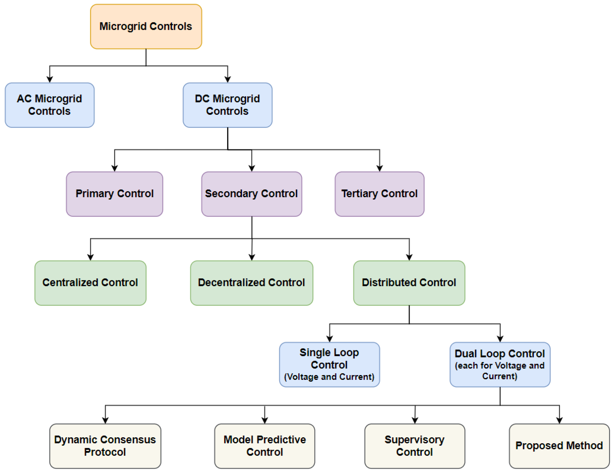
Figure 1. Structure of the research.
Sustainability 16 01204 g001
Figure 2. Buck converter equivalent circuit diagram.
Sustainability 16 01204 g002
Figure 3. Buck converter block diagram.
Sustainability 16 01204 g003
Figure 4. Buck converter primary control within a DC microgrid.
Sustainability 16 01204 g004
Figure 5. Islanded DC microgrid schematics.
Sustainability 16 01204 g005
Figure 6. Reduced communication topology.
Sustainability 16 01204 g006
Figure 7. Proposed DC microgrid secondary distributed control.
Sustainability 16 01204 g007
Figure 8. Implemented hybrid FFA–PSO flowchart.
Sustainability 16 01204 g008
Figure 9. DC bus voltage during state-space analysis.
Sustainability 16 01204 g009
Figure 10. Output current during state-space analysis. (a) DER 1; (b) DER 2; (c) DER 3.
Sustainability 16 01204 g010
Figure 11. Real-time testing system schematic.
Sustainability 16 01204 g011
Figure 12. DC bus voltage.
Sustainability 16 01204 g012
Figure 13. Current output of each DER with newly introduced secondary control.
Sustainability 16 01204 g013
Figure 14. Signal outputs of the newly introduced secondary control.
Sustainability 16 01204 g014
Figure 15. DC bus voltage under load variations.
Sustainability 16 01204 g015
Figure 16. Each DER output current under load variations.
Sustainability 16 01204 g016
Figure 17. Proposed secondary control signal outputs under load variations.
Sustainability 16 01204 g017
Figure 18. Each DER current output under communication delays.
Sustainability 16 01204 g018
Figure 19. DC bus voltage under communication delays.
Sustainability 16 01204 g019
Figure 20. Proposed secondary control output signals under communication delays.
Sustainability 16 01204 g020
Table 1. DC microgrid state-space model parameters.
Parameters Symbols Values
Nominal Bus Voltage U r 48 V
Voltage Source U s i 100 V
Switching Frequency f s w 10 kHz
Filter Inductance and Capacitance L , C 10 mH, 200  μ F
Load R L j j = 1 , 3 Ω , 5  Ω , 5  Ω
Hybrid FFA–PSO Algorithm Parameters
Maximum no. of Iterations i t e r a t i o n m a x 300
Population Size P o p 50
Inertia Constants w i , w f 0.9, 0.5
Maximum Velocity V m a x 0.1( Y m a x Y m i n )
Minimum Velocity V m i n V m a x
Acceleration Coefficients c 1 = c 2 1.49
Attractiveness at Origin η o 2
Absorption Coefficient γ 1
Randomization Factor σ 0.5
No. of Design Variables φ 1
Primary Controls
Droop Resistance R d i i = 1 , 3 Ω
Current Loop K i p , K i i 2.5, 5
Voltage Loop K v p , K v i 0.248, 2
Table 2. DC microgrid secondary and primary control eigenvalue analysis.
Mode Primary   Control Secondary   Control
λ 1 −158.35−278.68 + i347.11
λ 2 8.65 + i105.21−278.68 − i347.11
λ 3 8.65 − i105.21−15.60
λ 4 −10.87−9.54
λ 5 −5.2 + i75.40−11.38
λ 6 −5.2 + i75.40−1.03 + i5.08
λ 7 −3.8 + i56.54−1.03 − i5.08
λ 8 −3.8 + i56.54−367.94
λ 9 −3.41− 367.94
λ 10 −3.41−1.03 + i5.08
λ 11 −1.03 − i5.08
λ 12 −5.49
λ 13 −5.49
Table 3. Microgrid parameters for real-time simulation.
Parameters Symbols Values
Voltage Source U s i 100 V
Switching Frequency f s w 10 kHz
Nominal Bus Voltage U r 48 V
Line Resistance R l n , i i = 1 , 4 0.2  Ω , 0.3 Ω , 0.5 Ω , 0.6 Ω
Filter Capacitance and Inductance C , L 120  μ F, 20 mH
Constant Power Load R C P L 200 W
Resistive Load R L j j = 1 , 3 Ω , 5  Ω , 5  Ω
Primary Controls
Droop Resistance R d i i = 1 , 4 Ω
Current Loop K i p , K i i 0.05, 148
Voltage Loop K v p , K v i 0.248, 36
Secondary Controls
Coefficient of Voltage Deviation α 1.25
Coefficient of Current Deviation β 7.5
Table 4. Proposed technique compared with other control schemes based on time response.
Control Objectives H 1 H 2 H 3 H 4 Proposed
Voltage Regulation2 s1.3 s1.72 s3 s≤0.2 s
Current Sharing2.8 s1.5 s2 s3.4 s≤1.4 s
Robustnesslowhighmoderatelowvery high
Implementation Complexitysimplecomplexsimplesimplecomplex
Disclaimer/Publisher’s Note: The statements, opinions and data contained in all publications are solely those of the individual author(s) and contributor(s) and not of MDPI and/or the editor(s). MDPI and/or the editor(s) disclaim responsibility for any injury to people or property resulting from any ideas, methods, instructions or products referred to in the content.