Article

Implementation of Non-Isolated High Gain Interleaved DC-DC Converter for Fuel Cell Electric Vehicle Using ANN-Based MPPT Controller

1
Department of Electrical and Electronics Engineering, SRM Institute of Science and Technology, Kattankulathur, Chennai 603203, India
2
Department of Mechanical Engineering, College of Engineering, King Khalid University, P.O. Box 394, Abha 61421, Saudi Arabia
3
Center for Engineering and Technology Innovations, King Khalid University, Abha 61421, Saudi Arabia
*
Authors to whom correspondence should be addressed.
Sustainability 2024, 16(3), 1335; https://doi.org/10.3390/su16031335
Submission received: 7 December 2023 / Revised: 19 January 2024 / Accepted: 29 January 2024 / Published: 5 February 2024

Abstract

:
A high conversion ratio DC-DC converter is crucial for fuel cell electric vehicles (FCEV). A fuel cell-based non-isolated high gain integrated DC-DC converter for electric vehicles is proposed in this paper. The system comprises an interleaved boost converter (IBC) at the source end, a switched capacitor cell, coupled inductors, a passive clamp circuit, and a voltage multiplier circuit (VMC). Its significance is to achieve the voltage conversion gain of 12.33 at a conversion ratio of 0.45. The idea is to use a proton exchange membrane fuel cell to power electric vehicles through a high-gain DC-DC converter. The use of an ineffective MPPT can result in lower energy conversion efficiency. Thus, this system incorporates a maximum power point tracking (MPPT) controller based on a neural network, which relies on the radial basis function network (RBFN) algorithm to track the maximum power point of the PEMFC accurately. The comparative study of the fuel cell electric vehicle (FCEV) structure with the RBFN-based MPPT technique was evaluated with that of the fuzzy logic technique using the MATLAB/Simulink platform (R2021b (MATLAB 9.11)). A 1.5 kW experimental prototype is designed with a switching frequency of 10 kHz to validate the design analysis, and its pursuance is compared between RBFN and FLC-based controllers. This manuscript will be a significant contribution towards evidencing a sustainable environment.

1. Introduction

As we strive for sustainable development, we face several demanding issues like climate change, resource depletion, and global warming. These challenges require expeditious attention and must be familiar to ensure a sustainable future. The rise in global temperatures is primarily caused by burning fossil fuels for energy production, industry, and transportation. To create a sustainable environment, we must rely on technological advancements. This article explores a solution to the use of combustion engine-based vehicles. The automotive industry’s progress is known to contribute to improving environmental sustainability.
Many auto sectors are keen on developing clean energy technologies for powering EVs. PEMFC [1] based electric vehicles are considered efficient alternatives to internal combustion (IC) engines because of their greater current density, clean power generation, higher efficacy, and naturally amiable features. Thus, fuel cell vehicles are a significant component of clean energy vehicles and have been used extensively in real-world applications [2,3]. Promising technological developments such as fuel cell-based electric vehicular systems play a significant role in developing a green and clean energy environment.
A fuel cell can be categorized as a phosphoric acid fuel cell (PAFC), a solid oxide fuel cell (SOFC), an alkaline fuel cell (AFC), a proton exchange membrane fuel cell (PEMFC), or a molten carbonate fuel cell (MCFC), depending on the type of electrolyte it uses [4]. PEMFCs are pioneers in the automotive industry because of their low operational temperature conditions and rapid start-up. Fuel-cell electric vehicles are in demand due to their durability and reliability, which makes them commercially viable [5,6].
In a fuel cell, the voltage at the output side is determined through electrochemical reactions and the cell’s temperature. There is no stable nonlinearity between voltage and current in fuel cells. As a result, fuel cells can only operate at maximum voltage and power. MPPT is an algorithm that measures maximum power points (MPP) at that operating point. The tracking of the maximum power point (MPP) is required to extricate the extreme amount of power from the PEMFC under dissimilar operational circumstances. Numerous MPPT techniques were documented in the literature, for instance, sliding mode control, perturb and observe (P&O), incremental conductance (INC), particle swarm optimization (PSO), fuzzy logic control (FLC), and controllers based on neural networks that can detect the maximum power point (MPP) in [7,8]. Among these MPPT algorithms, perturb and observe (P&O) are the most popular and most accessible to implement [9,10,11]. A steady state oscillation caused by P&O and incremental conductance methods will degrade the overall efficiency of the fuel cell [12]. The MPP is tracked more efficiently and accurately with neural networks and fuzzy logic controller-based algorithms to overcome this problem [13]. This study suggests that an MPPT controller with a radial basis function network (RBFN) tracks the PEMFC’s MPP. Figure 1 shows the illustration of the FCEV system.
The output voltage of the fuel cell is unregulated, which is relatively low and approximately in the range of about 30–45 V. Therefore, the proton exchange membrane fuel cell (PEMFC) voltage must be boosted and regulated using a DC-DC converter. For EVs, boost converters are used widely as front-end power conditioners. Conventional DC converters are utilized for low-power applications as a power electronic interface. The boost converter’s slow current management and thermal handling capability might not be appropriate for high-power applications. Isolated DC-DC converters can achieve better voltage conversion gain using either a one-coupled inductor or high-frequency transformers, as demonstrated in [14]. However, the windings in the transformer reduce the efficiency of the converter. A SEPIC converter with an isolated transformer is proposed in [15]. However, isolated DC converters are more expensive than non-isolated-based DC converters. A single-switch converter with a lower diode voltage stress is implemented in [16]. The voltage gain obtained is not sufficient to drive EVs. A switched capacitor with an active network is proposed in [17]. Although more efficient, they have shortcomings like circuit complication, augmented volume, and greater costs. Step-up converters with voltage multiplier units are proposed in [18]. However, a single multiplier cell cannot drive the FCEV’s power train with enough voltage. Many types of high-gain converters have been designed in the literature to address these problems, and the recommended converter is compared with [16,17,18,19,20,21,22,23,24,25].
High-gain DC converters are essential to achieve efficient, compact, and high-power conversion systems in electric vehicles. Such converters offer reduced input currents, which put less strain on electrical components such as switches, inductors, and capacitors. As a result, the components last longer and are more reliable. Even with erratic voltage from the fuel cell, a high-voltage gain maintains stable output. Hence, this manuscript suggests a non-isolated-based high-gain interleaved DC-DC converter to achieve better voltage gain and low switching stress in fuel cell applications.
To propel the electric vehicle using the BLDC motor, the DC converter’s voltage is fed to the voltage source inverter. The BLDC motor has excellent traction properties, including higher torque and efficiency. Its traction characteristics make BLDC motors ideal for electric vehicles [26,27]. Figure 2 depicts the suggested converter-fed BLDC motor-driven electric vehicular system.
The novelty and highlights of the suggested DC converter are given below,
  • A high voltage gain (of about 12.33) is attained by engaging voltage gain extension methods. The coupled inductor improves the voltage gain by altering the number of turns of inductor coils, and further additional voltage gain is provided by switched capacitor cells.
  • In order to achieve a higher voltage gain, the switches are operated at a minimal duty ratio of 0.45.
  • With a phase shift of 180°, the two interleaved phases can produce ripple-free input current. The ripple on the input current is reduced since the entire input current is split throughout the interleaved segments.
  • The lossless clamp circuit recirculates the coupled inductors’ leakage inductance to the output side, effectively suppressing the reverse-recovery concern of diodes.

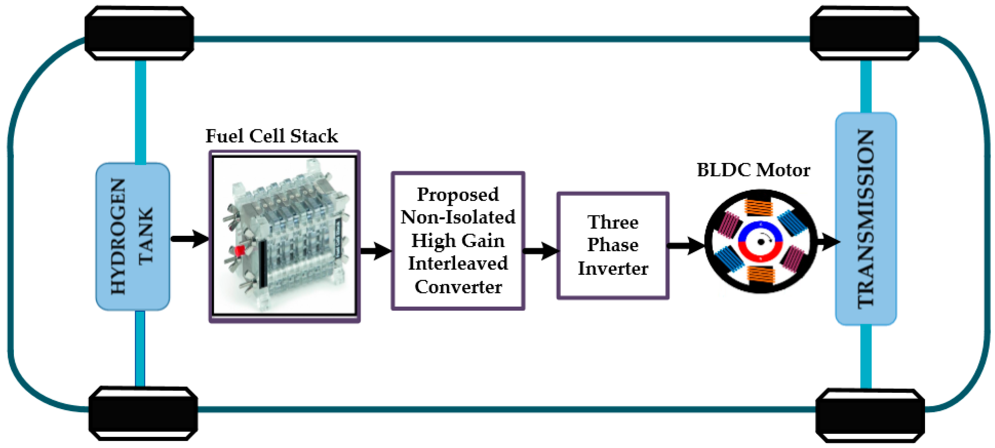
2. Architecture of the FCEV System

The fuel cell is connected to the BLDC motor through the proposed non-isolated high gain interleaved DC-DC converter and three-phase inverter. The voltage of the fuel cell is insufficient to drive a BLDC motor. BLDC motors in electric vehicles require high acceleration, speed, and torque. Thus, the fuel cell voltage is boosted with the help of the suggested high-gain DC-DC converter. Then, the output voltage of the proposed DC converter is inverted using a three-phase voltage source inverter, which will drive the BLDC motor. A radial bias function network is utilized to determine the maximum power point of the fuel cell.

Modeling of PEMFC

The proton exchange membrane fuel cell (PEMFC) is an electrochemical device that alters the chemical energy stored in fuel into electrical energy. Figure 3 shows the schematic layout of the fuel cell [28]. Air and fuel are the two inputs of the fuel cell. The electrochemical conversion process produces electricity, and hydrogen is used as a fuel. PEMFC is a stack of fuel cells, and each cell contains two electrodes and an electrolyte. The cathode and anode are the two electrodes, and an electrolyte is composed of polymer electrolyte membranes (PEM). An electrolyte separates hydrogen ions into positive and negative charges. H2 and O2 are fed into the fuel cells, and electricity is produced due to the electrochemical process. In a fuel cell, heat and water are the only waste products. Figure 4 shows the general electrical circuit of the PEMFC. The fuel cell voltage is given by [29,30]
V F C = E n e r s t V a c t V o h m V c o n
where Enernst is the open circuit thermodynamic voltage, Vohm is the activation overvoltage, Vact is the activation overvoltage, and Vcon is the concentration voltage.
E n e r s t = 1.229 8.5 × 10 4   T 298.15 + 4.308 × 10 5 T [ ln P H 2 + 0.5 P O 2 ]
where T is the absolute temperature in Kelvin, and PO2 and PH2 are the partial pressures of O2 and H2 in atm. Vact represents the combined activation voltage on the cathode and anode. It is given by,
V a c t = [ δ 1 + δ 2 T + δ 3 T l n C O 2 + δ 4 T l n ( I F C ) ]
where δi (i = 1, 2, 3, 4) represents an empirical coefficient for each fuel cell, and CO2 denotes the oxygen concentration in the liquid or gas.
C O 2 = P O 2 5.08 × 10 6 × e ( 498 T )
Vohm is the ohmic overvoltage and is given by
V o h m = I F C   ( R C + R M )
where RM is the resistance of the electron, and RC is the resistance of the proton. RC is a constant.
R M = ρ m L A
where L is the width of the membrane in cm, A is the membrane’s active area in cm2, and ρm is the specific resistivity of the membrane in Ω-cm. ρm is given by
ρ m = 181.6 [ 1 + 0.03 J + 0.062 ( T / 303 ) 2 J 2.5 ] [ G 0.634 3 J ] e [ 4.18 1 303 T ]
where G is the amount of water content in the membrane, and the J-current density is given by
J = I F C A
where Vcon is the concentration voltage and is given by
V c o n = R T n F ln ( 1 J J m a x )
where F is Faraday’s constant, R is a universal gas constant, and Jmax is the max current density. The fuel cell is connected to the proposed DC converter to retain a constant DC voltage. The design parameters for the simulation of a 1.26 kW PEMFC are presented in Table 1.

3. Non-Isolated High Gain Interleaved Converter

The projected high-gain DC-DC converter consists of an interleaved element, a switched capacitor cell (SC cell), a clamp circuit, and a voltage multiplier module. L1P and L2P are the primary coupled inductances and are associated in parallel, and the L2S and L1S are the secondary coupled inductances associated with a series connection. The interleaved arrangement will exterminate the input current ripple, which is composed of two semiconductor switches, S1 and S2, and two primary coupled inductors, L1P and L2P. The SC cell has two diodes, D1 and D2, and capacitors C1 and C2. The switched capacitor cell progresses the whole voltage gain. Figure 5 shows the proposed interleaved DC converter.
The clamping circuit has two clamp diodes, D3 and D4, and one clamping capacitor, C3. It reduces the voltage stress on semiconductor devices by reducing leakage currents in the coupled inductors. The VMU supplies two secondary coupled inductors; two regenerative diodes are connected to it, and two regenerative capacitors are supplied by it. The suggested DC converter functions under a continuous conduction mode (CCM). There are six stages in the proposed converter from stage I [t0–t1] to stage VI [t5–t6], and each stage is explained below. The theoretical key waveforms of the suggested DC converter are presented in Figure 6. The operational stage of the suggested converter is shown in Figure 7.
  • Stage I [t0–t1]
In stage I, S1 is conducting, and S2 is off-state. The diodes D2 and D5 are in a conducting state, and all other diodes D1, D3, D4, D6, and D0 are in the off condition. The primary inductance L1P is charged through the fuel cell voltage. The current of the primary inductances L1P and L2P will start to increase linearly. Stage I is shown in Figure 7a.
  • Stage II [t1–t2]
S1 is still conducting in this stage, and S2 will start to conduct. The diodes D2 and D5 are still in a forward-biased state. The diodes D1, D3, D4, D6, and D0 are in an off condition. The current of the primary inductances L1P and L2P will increase linearly. The energy of the output capacitor C0 supplies the load. Stage II is shown in Figure 7b.
  • Stage III [t2–t3]
S1 is in an off condition, while S2 is still ON. Through D2, energy is stored in the primary inductances and charges the capacitor C1. Thus, the current through primary inductances will start to decrease. The diodes D3, D5, and D0 are in the conducting state. The secondary inductances L1S and L2S will begin to energize, and capacitor C4 will be charged. The diodes D1, D4, and D6 are in the off-state. Stage III is depicted in Figure 7c.
  • Stage IV [t3–t4]
In this stage, S1 and S2 remain as in the previous stage. In this stage, C1 is fully charged, and the potential difference is developed, which turns off the diodes D2 and D3. The energy stored in secondary inductors L2S and L1S will forward bias D5. The primary inductors charge the capacitors C2 and C3. Diodes D1, D4, D5, and D0 are in the conducting state. Diode D6 is still in the reverse-biased state. Stage IV is shown in Figure 7d.
  • Stage V [t4–t5]
In this stage, S2 remains in an off condition, and switch S1 is in an ON state. The switch S1 energizes capacitor C3. Here, C4 is fully charged, and the potential difference is developed across C3, which forward biases the diode D5. The diodes D2 and D5 are in a reverse-biased state, and all other diodes are in a forward-biased state. The secondary inductors L2S and L1S will charge the capacitor C5. The load R0 is supplied through D0. Stage IV is shown in Figure 7e.
  • Stage VI [t5–t6]
In this stage, S2 remains OFF, and S1 remains ON. The diodes D1, D3, D4, D5, and D6 are under a reverse-biased state. The current through capacitors C1 and C3 increases due to the primary inductor L1P. The diode D2 is in the ON state, and the current pathway will be L1P-C1-D2-L2P. When S1 is in the OFF condition, stage 1 begins. Stage IV is shown in Figure 7f.

3.1. Analysis of the Proposed Converter

The voltage gain equation of the suggested converter can be derived using the output voltage equation of a conventional interleaved boost converter, which is given by
V 0 = 1 1 D V F C
The capacitor’s C1 and C2 voltages might be considered as the conventional boost converter’s output voltages.
The capacitor’s voltage C1 and C2 can be written as,
V C 1 = V C 2 = 1 1 D V F C
The capacitor voltage C3 is given by
V C 3 = V C 1 + V C 2 = 2 1 D V F C
From stage 3 to stage 4, switch S2 is conducting, and S1 is in the off state. From stage 5 to stage 6, switch S2 is in the OFF state, and S1 is in an ON state. Volt-sec balance is used with a coupled inductor, and the expression can be given as,
0 D T S V L 2 P I I I I V d t + D T S T S V L 2 S V V I d t = 0
V L 2 P I I I I V = V L 2 S I I I I V = N B K 2 V F C
By substituting (7) in (6), the expression for V L 2 S V V I can be derived as,
V L 2 S V V I = N B K 2 V F C D ( 1 D )
Likewise, we can obtain V L 1 S I I I I V ,
V L 1 S I I I I V = N A K 1 V F C D 1 D  
where K1 and K2 are coupling coefficients of coupled inductors 1 and 2. Applying KVL to the voltage multiplier unit for stage 3 and VC4 can be written as,
V C 4 = V L 2 S I I I I V V L 1 S I I I I V
Substitute (14) and (16) in (17)
V C 4 = N B K 2 V F C + N A K 1 V P V D ( 1 D )
V L 2 S V V I can also be written as,
V L 1 S V I V = N A V L 2 P = N A K 1 V F C
Applying KVL to the voltage multiplier unit for stage 5, the equation can be written as
V C 5 V C 4 = V L 1 S V V I V L 2 S V V I
Substituting (15) and (19) in (20),
V C 5 V C 4 = N A K 1 V F C + N B K 2 V F C D ( 1 D )
By substituting (18) in (19),
V C 5 = N A K 1 V F C + N B K 2 V F C ( 1 D )
The output voltage can be determined from the output capacitor C0 as,
V 0 = V C 1 + V C 2 + V C 3 + V C 4 + V C 5
Voltage gain can be obtained by substituting (11), (12), (18), and (22) in (23) and also substituted by   N A = N B = N , K 1 = K 2 = K ,
M = V 0 V F C = 4 + 3 N ( 1 D )
The voltage stress of the switches S1 and S2 can be given by
V S 1 = V S 2 = 1 1 D V F C
The voltage across the diodes in terms of V0 can be written as,
V D 1 = V D 2 = 2 V 0 4 + 3 N
V D 3 = V D 4 = V 0 4 + 3 N
V D 5 = V D 6 = 2 V 0 ( 1 + N ) ( 4 + 3 N )
The voltage across the capacitors in terms of V0 can be written as,
V C 3 = 2 V 0 4 + 3 N
V C 1 = V C 2 V 0 4 + 3 N
V C 4 = V C 5 = 2 V 0 ( 1 + N ) ( 4 + 3 N )
The coupled inductance can be written as,
L 1 = L 2 = D ( 1 D ) V F C ( 4 + 3 N ) f s I 0
Since the clamping circuit in the proposed converter reduces the leakage currents in the coupled inductors, the leakage inductance is neglected in the voltage gain analysis.

3.2. Comparison of the Proposed Converter

The suggested non-isolated high-gain interleaved DC converter is compared to other high-gain DC converters offered in [16,17,18,19,20,21,22,23,24,25]. Table 2 depicts the comparison of the proposed converter with [16,17,18,19,20,21,22,23,24,25]. The projected converter is compared using the voltage gain and duty ratio. Figure 8 depicts the voltage gain vs duty ratio of the suggested converter.
Figure 9 shows that the recommended converter is compared with [16,17,18,19,20,21,22,23,24,25], which has a high voltage gain of 12.33 at a duty ratio of 0.45. The suggested converters have a main advantage over other converters in [16,17,18,19,20,21,22,23,24,25], as they can increase the input voltage to a higher output voltage while maintaining a superior nominal conversion ratio and voltage gain. These converters are beneficial in EV applications since they can typically operate over a wide input voltage range. However, they have their own drawbacks, such as having more components than [16,17,18,19,20,21,22,23,24,25]. This could put additional stress on them and reduce their dependability.

4. Design of RBFN-Based MPPT Controller

An RBFN controller is built for the proposed setup, and its outcomes are evaluated against fuzzy logic control. The radial basis function network (RBFN) is a feed-forward neural network algorithm that includes supervised and unsupervised learning phases. It has three layers: an input layer, a hidden layer, and an output layer. Figure 10 displays the structure of the RBFN. The RBFN’s hidden layer utilizes a non-linear activation function, while its output layer employs a linear activation function [31,32].
The maximum extent of power that can be drawn from the PEFM by the RBFN-based MPPT method is explored. The system can track and adjust to the optimal operating point using an iterative, real-time measurement-based approach called RBFN-based MPPT. In order to identify the ideal operating point for maximum power generation, the RBFN needs to be trained. A dataset with a range of input combinations and their corresponding optimal power points is used during training. Based on this data, the network modifies its internal variables to discover the mapping between inputs and ideal power outputs. After analyzing the previously measured fuel cell parameters, the RBFN generates a control signal that modifies the operating point of the high-gain DC-DC converter. Hidden layer inputs are transmitted by nodes of the input layer. As a result of the input neuron, the net output neuron is represented as follows [33,34,35,36]:
x     i 1 n = n e t i ( 1 )
  y   i ( 1 ) = f   i ( 1 ) n e t   i 1 n = n e t   i ( 1 ) n , i = 1,2
x   i ( 1 ) : Input layer
y   i ( 1 ) : Hidden layer
n e t   i ( 1 ) : Sum of input layers.
The nodes in the hidden layer implement the Gaussian function. This function membership function is given by [37,38]
x j ( 2 ) n = X M j T j X M j
y j ( 2 ) n = f j ( 2 ) n e t k 2 n = e n e t j ( 2 ) n j = 1,2
where Mj and ∑j are the mean and SD of the Gaussian function.
The single node (k) in the output layer produces the duty ratio (D).
n e t k ( 3 ) = j w j y j ( 2 )
y k ( 3 ) n = f k ( 3 ) n e t k 3 n = n e t k ( 3 ) ( n )
Wj is a connective weight matrix between the output and hidden layer.
In this study, the voltage and current of the fuel cell are used as inputs to the radial bias function network controller, which then outputs the duty ratio (D), as illustrated in Table 3. Figure 11 shows the MATLAB structure of the RBFN.

5. Electronic Commutation of the BLDC Motor

Because of the BLDC’s compact structure, high power, high power factor, noiseless operation, and higher efficiency, the use of BLDC motors in variable-speed drives has become more prevalent. The BLDC is preferred for the proposed work, and switches in the voltage source inverter (VSI) are operated through the electronic commutation of brushless DC motors [26,27]. The regulation of the speed of a motor is dependent on the position of its rotor. Three Hall sensors are mounted 120 degrees apart to sense the rotor’s location. These sensors generate Hall signals at every 60-degree interval, depending on the position of the rotor. A decoder circuit converts these Hall signals into gate pulses for the voltage source inverter. Table 4 displays the electronic commutation sequence of the BLDC motor.

6. Simulation Results and Discussions

The MATLAB/Simulink platform is utilized to simulate MPPT controllers based on the radial bias function network (RBFN) and fuzzy logic controller (FLC). The recommended non-isolated high gain interleaved DC converter is simulated by the parameters given in Table 5. A FCEV system’s dynamic response is studied by considering impulsive variations in the temperature of the fuel cell, which is shown in Figure 12. Different physical and electrochemical processes in a fuel cell stack lead to temperature changes over time. According to Figure 12, the power output of a fuel cell varies with temperature, reaching its maximum at 378 °K.
Fuel cells should be operated at their optimal temperature to maximize performance and improve electrochemical reactions [30]. Here are the temperature changes: T = 340 °K for a time interval t = 0 to 0.3 s. T = 308 °K for a time interval of t = 0.3 s to 0.5 s. T = 378 °K for a time interval t = 0.5 s to 0.7 s T = 356 °K for a period of time t = 0.7 s to 1.0 s. For the temperature change, the output voltage of the PEMFC (VFC), the output current of the fuel cell (IFC), and the output power of the fuel cell (PFC) are depicted in Figure 13, Figure 14 and Figure 15. The fuel cell current is zoomed, and it is found that the input current ripple is low, and the fuel cell current is about 18 A. The voltage fluctuation applied to the electric drive system can affect vehicle performance. This may result in reduced responsiveness to changes in driving conditions or decreased acceleration and efficiency. However, the employed ANN-based controller will regulate the output voltage and maintain stability under varying operating conditions. The maximum power generated by a fuel cell between t = 0 s to t = 0.3 s is 450 watts, t = 0.3 s to t = 0.5 s is 260 watts, t = 0.5 s to t = 0.7 s is 690 watts, and t = 0.7 s to t = 1.0 s is 590 watts. The output current of the converter with RBFN controller is shown in Figure 16, and it is found to be 6.8 A. In addition, Figure 17 displays the boosted converter output voltage of 370 V achieved by the proposed converter with an RBFN controller. Finally, Figure 18 illustrates the power generated by the proposed converter with the RBFN controller.
The maximum power generated by the proposed converter using the RBFN technique is 1197 W, 900 W, 2503 W, and 2155 W for temperatures 340 °K, 320 °K 360 °K, and 350 °K, respectively. Figure 19, Figure 20 and Figure 21 show the DC output power (PDC), DC output voltage (VDC), and DC output current (IDC) of the suggested converter with the fuzzy-based MPPT technique. Fuzzy logic controllers are capable of efficiently managing non-linear systems. DC converters may behave nonlinearly, particularly when they are running under fluctuating load conditions. With the use of FLCs, control performance may be enhanced, and output voltage changes can be reduced by designing control rules that adjust to the non-linear features of the system. It is also noticed that though the ripple is less in the FLC, the output power of the converter is reduced compared to the RBFN controller.
The maximum power generated by the suggested converter with a fuzzy-based MPPT technique is 868 W, 645 W, 1788 W, and 1536 W for temperatures 340 °K, 320 °K, 360 °K, and 350 °K, respectively. Figure 22 displays the contrast of the output power of the proposed DC converter with the RBFN and FLC-based MPPT techniques. Figure 22 shows that the suggested RBFN controller produces a higher power than the fuzzy-based controller. MPPT techniques based on FLC and RBFN are compared and given in Table 6.
The characteristics of a motor at different temperatures of PEFM cells are depicted in Figure 23, Figure 24, Figure 25, Figure 26, Figure 27 and Figure 28. At various temperature conditions of the PEFM cell, stator currents (Isa), (Isb), and (Isc), back EMF (E), torque (Te), and speed (N) of the BLDC motor are given. Table 6 shows the comparison of the output voltage Vdc (V), output current Idc (A), and output power Pdc (W) of the proposed converter for PEMFC with RBFN and FLC-based MPPT.

7. Hardware Results and Discussions

Table 7 displays the hardware components utilized for developing a prototype of the recommended non-isolated high gain interleaved DC converter, which is based on fuel cell technology and capable of producing 1.5 KW of power. Figure 29 shows the experimental prototype for the proposed DC converter. A 30 V DC supply is chosen as input for the recommended DC converter for the hardware implementation. An RBFN and FLC-based controller was implemented to produce gate pulses to the switches S1 and S2, and their corresponding voltage and current were measured. The proposed control technique is implemented with a switching frequency of 10 kHz using an FPGA-SPARTAN 6 processor. The RBFN and FLC-based model is developed in MATLAB and converted to VHDL using Xilinx-ISE. Thus, the FPGA-SPARTAN 6 generates the gate pulses and is given to S1 and S2. A 30 V DC is boosted to 370 V by the proposed converter. Three-phase VSI changes the DC voltage into AC voltage and then distributes it to the BLDC motor. The hardware results of the suggested high gain converter’s DC voltage (V0) and DC (I0) are compared for both the RBFN and FLC-based MPPT techniques. The stator currents (Isa, Isb, Isc), EMF (E), speed (N), and torque (Te) of the BLDC motor were also measured.
Figure 30 shows the stator current of the BLDC motor for three phases, ISA, ISB, and ISC, which is about 15 A. Figure 31 shows the position of the rotor signal, which varies from −25 V to +25 V. Figure 32 depicts the experimental waveforms of the suggested DC converter for the RBFN controller. VGS1 and VGS2 are gate pulse voltage for switches S1 and S2, which is 10 V. V0RBFN are output voltages of the recommended high gain converter where RBFN controller is found to be 380 V. I0RBFN are output currents of the suggested high gain DC converter where the RBFN controllers are 7 A. Figure 33 depicts the performance of the BLDC motor for the RBFN controller. The speed, torque, and back EMF of the BLDC motor for the RBFN controller are 2300 RPM, 30 Nm, and 200 V.
Figure 34 shows the hardware waveforms of the recommended high-gain DC converter for the FLC controller. V0FLC, the output voltage of the proposed high gain DC converter with an FLC controller, is 300 V. I0FLC, the output current of a proposed converter with an FLC controller, is 4.2 A. VGS1 and VGS2 are gate pulse voltages for switches S1 and S2, which is 10 V for the FLC controller. Figure 35 depicts the performance of the BLDC motor for the FLC controller. The torque, back EMF, and speed of the BLDC motor for the FLC controller are 42 Nm, 250 V, and 2000 RPM, respectively. The hardware results depict that the performance of the recommended converter with RBFN controller is superior to the FLC controller.

8. Conclusions

This manuscript suggests a non-isolated high-gain interleaved DC converter for fuel cell electric vehicular systems. The recommended high-gain DC converter is highly suitable for electric vehicular systems. The highlights of the recommended system can be narrated as,
  • The suggested converter has a conversion ratio of 12.33
  • The duty ratio of the MOSFETs is 0.45
  • The arrangement of switches is an interleaved structure that will provide a smooth, ripple-free input current.
A radial function network (RBFN) MPPT technique is used to extract the maximum power from the fuel cell. Also, a comparison is made between the proposed RBFN MPPT technique and the FLC-based MPPT controller. According to the simulation and hardware results, the RBFN-based MPPT controller tracked the maximum amount of power quicker than the fuzzy logic-based controller. The dynamic characteristics of BLDC motors show that the proposed controller is best suited to electric vehicular systems. A future version of the proposed converter could utilize gallium nitride (GaN) switches, known for their improved reliability and ruggedness compared to traditional semiconductor switches. Also, this proposed structure facilitates and contributes to sustainable approaches in electric transportation.

Author Contributions

Conceptualization, R.P.; Methodology, R.S. and C.A.S.; Validation, R.P.; Formal analysis, R.P.; Investigation, C.A.S.; Resources, S.A.; Data curation, R.P.; Writing—review & editing, C.A.S.; Supervision, S.A.; Funding acquisition, S.A. All authors have read and agreed to the published version of the manuscript.

Funding

This research was funded by the Deanship of Scientific Research at King Khalid University for funding this work through a large group project under grant number RGP2/106/44.

Data Availability Statement

No new data were created or analyzed in this study. Data sharing is not applicable to this article.

Acknowledgments

The authors extend their appreciation to the Deanship of Scientific Research at King Khalid University for funding this work through a large group project under grant number RGP2/106/44.

Conflicts of Interest

The authors declare no conflict of interest.

References

  1. Wang, F.-K.; Amogne, Z.E.; Chou, J.-H. A Hybrid Method for Remaining Useful Life Prediction of Proton Exchange Membrane Fuel Cell Stack. IEEE Access 2021, 9, 40486–40495. [Google Scholar] [CrossRef]
  2. Emadi, A.; Williamson, S.S. Fuel cell vehicles: Opportunities and challenges. In Proceedings of the IEEE Power Engineering Society General Meeting, Denver, CO, USA, 6–10 June 2004; Volume 2, pp. 1640–1645. [Google Scholar] [CrossRef]
  3. Refaat, S.S.; Ellabban, O.; Bayhan, S.; Abu-Rub, H.; Blaabjerg, F.; Begovic, M.M. Smart Transportation. In Smart Grid and Enabling Technologies; IEEE: Piscataway, NJ, USA, 2021; pp. 169–193. [Google Scholar] [CrossRef]
  4. Moghadari, M.; Kandidayeni, M.; Boulon, L.; Chaoui, H. Operating Cost Comparison of a Single-Stack and a Multi-Stack Hybrid Fuel Cell Vehicle Through an Online Hierarchical Strategy. IEEE Trans. Veh. Technol. 2023, 72, 267–279. [Google Scholar] [CrossRef]
  5. Petrovic, S.; Hossain, E. Development of a Novel Technological Readiness Assessment Tool for Fuel Cell Technology. IEEE Access 2020, 8, 132237–132252. [Google Scholar] [CrossRef]
  6. Yuan, H.-B.; Zou, W.-J.; Jung, S.; Kim, Y.-B. A Real-Time Rule-Based Energy Management Strategy With Multi-Objective Optimization for a Fuel Cell Hybrid Electric Vehicle. IEEE Access 2022, 10, 102618–102628. [Google Scholar] [CrossRef]
  7. Ali, A.; Almutairi, K.; Padmanaban, S.; Tirth, V.; Algarni, S.; Irshad, K.; Islam, S.; Zahir, M.H.; Shafiullah, M.; Malik, M.Z. Investigation of MPPT Techniques Under Uniform and Non-Uniform Solar Irradiation Condition–A Retrospection. IEEE Access 2020, 8, 127368–127392. [Google Scholar] [CrossRef]
  8. Chu, C.; Chen, C. Robust maximum power point tracking method for photovoltaic cells: A sliding mode control approach. Solar Energy 2009, 83, 1370–1378. [Google Scholar] [CrossRef]
  9. Esram, T.; Chapman, P.L. Comparison of Photovoltaic Array Maximum Power Point Tracking Techniques. IEEE Trans. Energy Convers. 2007, 22, 439–449. [Google Scholar] [CrossRef]
  10. Ram, J.; Rajasekar, N.; Miyatake, M. Design and overview of maximum power point tracking techniques in wind and solar photovoltaic systems: A review. Renew. Sustain. Energy Rev. 2017, 73, 1138–1159. [Google Scholar] [CrossRef]
  11. Tao, F.; Zhu, L.; Fu, Z.; Si, P.; Sun, L. Frequency Decoupling-Based Energy Management Strategy for Fuel Cell/Battery/Ultracapacitor Hybrid Vehicle Using Fuzzy Control Method. IEEE Access 2020, 8, 166491–166502. [Google Scholar] [CrossRef]
  12. Ali, M.N.; Mahmoud, K.; Lehtonen, M.; Darwish, M.M.F. An Efficient Fuzzy-Logic Based Variable-Step Incremental Conductance MPPT Method for Grid-Connected PV Systems. IEEE Access 2021, 9, 26420–26430. [Google Scholar] [CrossRef]
  13. Aly, M.; Rezk, H. A Differential Evolution-Based Optimized Fuzzy Logic MPPT Method for Enhancing the Maximum Power Extraction of Proton Exchange Membrane Fuel Cells. IEEE Access 2020, 8, 172219–172232. [Google Scholar] [CrossRef]
  14. Goyal, V.K.; Shukla, A. Isolated DC–DC Boost Converter for Wide Input Voltage Range and Wide Load Range Applications. IEEE Trans. Ind. Electron. 2021, 68, 9527–9539. [Google Scholar] [CrossRef]
  15. Singh, B.; Kushwaha, R. A PFC Based EV Battery Charger Using a Bridgeless Isolated SEPIC Converter. IEEE Trans. Ind. Appl. 2020, 56, 477–487. [Google Scholar] [CrossRef]
  16. Tseng, K.-C.; Huang, C.-C.; Cheng, C.-A. A Single-Switch Converter With High Step-Up Gain and Low Diode Voltage Stress Suitable for Green Power-Source Conversion. IEEE J. Emerg. Sel. Top. Power Electron. 2016, 4, 363–372. [Google Scholar] [CrossRef]
  17. Tang, Y.; Wang, T.; He, Y. A Switched-Capacitor-Based Active-Network Converter With High Voltage Gain. IEEE Trans. Power Electron. 2014, 29, 2959–2968. [Google Scholar] [CrossRef]
  18. Baddipadiga, B.P.; Ferdowsi, M. A high-voltage-gain dc-dc converter based on modified dickson charge pump voltage multiplier. IEEE Trans. Power Electron. 2017, 32, 7707–7715. [Google Scholar] [CrossRef]
  19. Wu, B.; Li, S.; Liu, Y.; Smedley, K.M. A New Hybrid Boosting Converter for Renewable Energy Applications. IEEE Trans. Power Electron. 2016, 31, 1203–1215. [Google Scholar] [CrossRef]
  20. Zhang, S.; Xu, J.; Yang, P. A single-switch high gain quadratic boost converter based on voltage-lift-technique. In Proceedings of the 2012 10th International Power & Energy Conference (IPEC), Ho Chi Minh City, Vietnam, 12–14 December 2012; pp. 71–75. [Google Scholar] [CrossRef]
  21. Tseng, K.-C.; Cheng, C.-A.; Chen, C.-T. High Step-Up Interleaved Boost Converter for Distributed Generation Using Renewable and Alternative Power Sources. IEEE J. Emerg. Sel. Top. Power Electron. 2017, 5, 713–722. [Google Scholar] [CrossRef]
  22. Hassan, W.; Lu, D.D.-C.; Xiao, W. Single-Switch High Step-Up DC–DC Converter With Low and Steady Switch Voltage Stress. IEEE Trans. Ind. Electron. 2019, 66, 9326–9338. [Google Scholar] [CrossRef]
  23. Meier, M.B.; da Silva, S.A.; Badin, A.A.; Romaneli, E.F.R.; Gules, R. Soft-Switching High Static Gain DC–DC Converter Without Auxiliary Switches. IEEE Trans. Ind. Electron. 2018, 65, 2335–2345. [Google Scholar] [CrossRef]
  24. Sathyan, S.; Suryawanshi, H.M.; Shitole, A.B.; Ballal, M.S.; Borghate, V.B. Soft-Switched Interleaved DC/DC Converter as Front-End of Multi-Inverter Structure for Micro Grid Applications. IEEE Trans. Power Electron. 2018, 33, 7645–7655. [Google Scholar] [CrossRef]
  25. Lai, C.-M.; Pan, C.-T.; Cheng, M.-C. High-Efficiency Modular High Step-Up Interleaved Boost Converter for DC-Microgrid Applications. IEEE Trans. Ind. Appl. 2012, 48, 161–171. [Google Scholar] [CrossRef]
  26. Kumar, P.H.; Somasekhar, V.T. An Enhanced Fault-Tolerant and Auto reconfigurable BLDC Motor Drive for Electric Vehicle Applications. IEEE J. Emerg. Sel. Top. Ind. Electron. 2023, 4, 368–380. [Google Scholar] [CrossRef]
  27. Naseri, F.; Farjah, E.; Ghanbari, T. An Efficient Regenerative Braking System Based on Battery/Supercapacitor for Electric, Hybrid, and Plug-In Hybrid Electric Vehicles with BLDC Motor. IEEE Trans. Veh. Technol. 2017, 66, 3724–3738. [Google Scholar] [CrossRef]
  28. Benyahia, N.; Denoun, H.; Zaouia, M.; Rekioua, T.; Benamrouche, N. Power system simulation of fuel cell and supercapacitor based electric vehicle using an interleaving technique. Int. J. Hydrogen Energy 2015, 40, 15806–15814. [Google Scholar] [CrossRef]
  29. Gong, W.; Cai, Z. Accelerating parameter identification of proton exchange membrane fuel cell model with ranking-based differential evolution. Energy 2013, 59, 356–364. [Google Scholar] [CrossRef]
  30. Reddy, K.J.; Sudhakar, N. High Voltage Gain Interleaved Boost Converter with Neural Network Based MPPT Controller for Fuel Cell Based Electric Vehicle Applications. IEEE Access 2018, 6, 3899–3908. [Google Scholar] [CrossRef]
  31. Czarnowski, I.; Jędrzejowicz, J.; Jędrzejowicz, P. Designing RBFNs Structure Using Similarity-Based and Kernel-Based Fuzzy C-Means Clustering Algorithms. IEEE Access 2021, 9, pp. 4411–4422. [Google Scholar] [CrossRef]
  32. Seghouane, A.-K.; Shokouhi, N. Adaptive Learning for Robust Radial Basis Function Networks. IEEE Trans. Cybern. 2021, 51, 2847–2856. [Google Scholar] [CrossRef]
  33. Afzal, A.; Navid, K.M.Y.; Saidur, R.; Razak, R.K.A.; Subbiah, R. Back Propagation Modeling of Shear Stress and Viscosity of Aqueous Ionic—MXene Nanofluids. J. Therm. Anal. Calorim. 2021, 145, 2129–2149. [Google Scholar] [CrossRef]
  34. Afzal, A.; Buradi, A.; Jilte, R.; Sundara, V.; Shaik, S.; Ağbulut, Ü.; Alwetaishi, M.; Saleel, C.A. Use of Modern Algorithms for Multi-Parameter Optimization and Intelligent Modelling of Sustainable Battery Performance. J. Energy Storage 2023, 73, 108910. [Google Scholar] [CrossRef]
  35. Khandal, S.V.; Razak, A.; Veza, I.; Afzal, A.; Alwetaishi, M.; Shaik, S.; Ağbulut, Ü.; Rashedi, A. Hydrogen and Dual Fuel Mode Performing in Engine with Different Combustion Chamber Shapes: Modelling and Analysis Using RSM-ANN Technique. Int. J. Hydrogen Energy 2024, 52, 973–1005. [Google Scholar] [CrossRef]
  36. Mokashi, I.; Afzal, A.; Khan, S.A.; Abdullah, N.A.; Bin Azami, M.H.; Jilte, R.D.; Samuel, O.D. Nusselt Number Analysis from a Battery Pack Cooled by Different Fluids and Multiple Back-Propagation Modelling Using Feed-Forward Networks. Int. J. Therm. Sci. 2021, 161, 106738. [Google Scholar] [CrossRef]
  37. Huddar, V.B.; Razak, A.; Cuce, E.; Gadwal, S.; Alwetaishi, M.; Afzal, A.; Saleel, C.A.; Shaik, S. Thermal Performance Study of Solar Air Dryers for Cashew Kernel: A Comparative Analysis and Modelling Using Response Surface Methodology (RSM) and Artificial Neural Network (ANN). Int. J. Photoenergy 2022, 2022, 4598921. [Google Scholar] [CrossRef]
  38. Afzal, A.; Khan, S.A.; Islam, T.; Jilte, R.D.; Khan, A.; Soudagar, M.E.M. Investigation and Back-Propagation Modeling of Base Pressure at Sonic and Supersonic Mach Numbers. Phys. Fluids 2020, 32, 096109. [Google Scholar] [CrossRef]
Figure 1. Illustration of FCEV system.
Sustainability 16 01335 g001
Figure 2. Proposed converter-fed BLDC motor-driven electric vehicle.
Sustainability 16 01335 g002
Figure 3. Schematic layout of the fuel cell [28].
Sustainability 16 01335 g003
Figure 4. Electrical circuit of the PEMFC [29].
Sustainability 16 01335 g004
Figure 5. Proposed non-isolated high gain interleaved converter.
Sustainability 16 01335 g005
Figure 6. Theoretical waveform of the proposed converter.
Sustainability 16 01335 g006
Figure 7. Operational stages of the proposed converter. (a) Stage I (t0–t1). (b) Stage II (t1–t2). (c) Stage III (t2–t3). (d) Stage IV (t3−t4). (e) Stage V (t4–t5). (f) Stage VI.
Sustainability 16 01335 g007aSustainability 16 01335 g007b
Figure 8. DC gains versus the duty cycle.
Sustainability 16 01335 g008
Figure 9. Comparison of the proposed converter with [16,17,18,19,20,21,22,23,24,25].
Sustainability 16 01335 g009
Figure 10. Structure of the radial basis function network (RBFN).
Sustainability 16 01335 g010
Figure 11. MATLAB structure of the RBFN.
Sustainability 16 01335 g011
Figure 12. Change of temperature in the fuel cell.
Sustainability 16 01335 g012
Figure 13. Output current of the fuel cell.
Sustainability 16 01335 g013
Figure 14. Output voltage of the fuel cell.
Sustainability 16 01335 g014
Figure 15. Output power of the fuel cell.
Sustainability 16 01335 g015
Figure 16. Output current of the converter with the RBFN.
Sustainability 16 01335 g016
Figure 17. Output voltage of the converter with the RBFN.
Sustainability 16 01335 g017
Figure 18. Output power of the converter with the RBFN.
Sustainability 16 01335 g018
Figure 19. Output current of the converter with the FLC.
Sustainability 16 01335 g019
Figure 20. Output voltage of the converter with the FLC.
Sustainability 16 01335 g020
Figure 21. Output power of the converter with the FLC.
Sustainability 16 01335 g021
Figure 22. Comparison of the power with the RBFN and FLC.
Sustainability 16 01335 g022
Figure 23. Stator phase current of the BLDC motor ISA.
Sustainability 16 01335 g023
Figure 24. Stator phase current of the BLDC motor ISB.
Sustainability 16 01335 g024
Figure 25. Stator phase current of the BLDC motor ISC.
Sustainability 16 01335 g025
Figure 26. Electromagnetic torque of the BLDC motor.
Sustainability 16 01335 g026
Figure 27. Back EMF of the BLDC motor.
Sustainability 16 01335 g027
Figure 28. Speed of the BLDC motor.
Sustainability 16 01335 g028
Figure 29. Experimental prototype of the proposed converter.
Sustainability 16 01335 g029
Figure 30. Stator current of the BLDC motor for the ISA, ISB, and ISC.
Sustainability 16 01335 g030
Figure 31. Hall sensor signals of the BLDC motor for HA, HB, and HC.
Sustainability 16 01335 g031
Figure 32. Hardware results of the proposed converter for the RBFN controller.
Sustainability 16 01335 g032
Figure 33. Dynamic performance of the BLDC motor for the RBFN controller.
Sustainability 16 01335 g033
Figure 34. Hardware results of the proposed converter for the FLC controller.
Sustainability 16 01335 g034
Figure 35. Dynamic performance of the BLDC motor for the FLC controller.
Sustainability 16 01335 g035
Table 1. Specifications of a 1.26 kW PEMFC.
ParametersRating
Maximum power (Pmax)1.26 kW
Maximum current (Imax)52 A
Maximum voltage P (max)34.8 V
No. of cells42
Temperature (T)54 °C
Fuel cell response time (s)1 s
Nominal air flow rate2400 IPM
Table 2. Performance comparison of the proposed converter with other topologies.
ReferenceNumber of
Switches
Number of DiodesNumber of CapacitorsNumber of
Cores
Voltage
Gain
Voltage Stress
of Switches
Converter in [16]1551 N 2 + D + 3 1 D V 0 N 2 + D + 3
Converter in [17]2332 3 + D 1 D V 0 3 + D
Converter in [18]2552 4 1 D V 0 4
Converter in [19]1441 3 D 1 D V 0 3 D
Converter in [20]1331 2 ( 1 D ) 2 V 0 2
Converter in [21]2231 2 + N 1 D V 0 2 + N
Converter in [22]1551 3 + 2 N 1 D V 0 3 + 2 N
Converter in [23]2421 2 + N D 1 D V 0 2 + N D
Converter in [24]2381 1 + D 1 D N V 0 N ( 1 + D )
Converter in [25]2434 2 1 D + N D V 0 2 + N D ( 1 D )
Proposed Converter2432 4 + 3 N 1 D V 0 4 + 3 N
Table 3. Parameters for the RBFN.
ParametersValues
Input variablesVFC, IFC
Input variablesDuty ratio
Spread factor0.01
Training algorithmOrdinary least squares
Maximum limit of the hidden neurons529
Table 4. Electronic commutation sequence of the BLDC motor.
θ (Degree)Hall SignalsVSI Switching States
HAHBHCS3S4S5S6S7S8
NA000000000
0–60101100100
60–120100100001
120–180110001001
180–240010011000
240–300011010010
300–360001000110
NA111000000
Table 5. Simulation parameters.
ComponentsParameters
Input voltage VFC30–35 V
Output voltage V0370 V
Switching frequency10 kHz
Duty cycle0.6
Turns ratio1
The capacitors C1, C24 μF
The capacitors C32.2 μF
The capacitors C4, C5650 nF
The capacitor C0470 μF
Table 6. Contrast of the DC power with RBFN and fuzzy-based MPPT controllers.
ParametersPEMFC with RBFN-Based MPPTPEMFC with Fuzzy-Based MPPT
Time Period (S)0 to 0.30.3 to 0.50.5 to 0.70.7 to 0.90 to 0.30.3 to 0.50.5 to 0.70.7 to 0.9
Fuel Cell
Temperature (°K)
340320360350340320360350
Output voltage VDC (V)258226368344253222374340
Output current IDC (A)4.64.16.76.13.32.84.74.3
Output power PDC (W)11979002503215586864517881536
Table 7. Components used in the hardware.
ComponentsParameters
The power MOSFET’s S1, S2IXTK 62N 25
The diodes D1, D2, D3, D4RF1001
The diodes D5, D6, D0MUR1560
The capacitors C0470 μF
The capacitors C1, C24 μF
The capacitors C32.2 μF
The capacitors C4, C5650 nF
Coupled inductorsEPCOS B66344
MotorBLDC
Disclaimer/Publisher’s Note: The statements, opinions and data contained in all publications are solely those of the individual author(s) and contributor(s) and not of MDPI and/or the editor(s). MDPI and/or the editor(s) disclaim responsibility for any injury to people or property resulting from any ideas, methods, instructions or products referred to in the content.

