

Towards a Future Hydrogen Supply Chain: A Review of Technologies and Challenges

Abstract
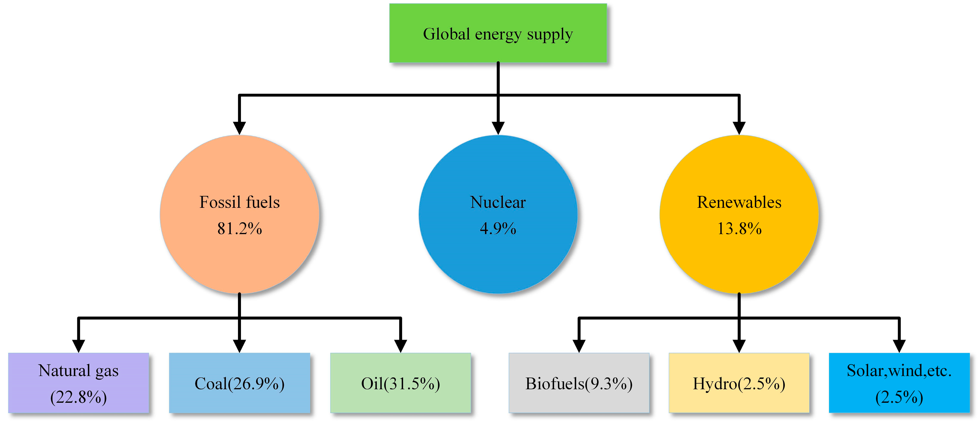
1. Introduction
2. Hydrogen Production
2.1. Hydrogen Production from Fossil Fuels
2.1.1. Steam Reforming

| Processes | Raw Materials | Example of Reactions | Temperature Range (°C) | Refs. |
|---|---|---|---|---|
| Steam reforming + water–gas shift | Natural gas, hydrocarbons | 700–1100 | [27,28] | |
| Renewable ethanol | ||||
| Partialoxidation | Natural gas, hydrocarbons | Thermal: 1300–1500; Catalytic: 700–1000 | [29,30] | |
| Ethanol | ||||
| Gasification | Coal | 700–1400 | [31,32] | |
| Biomass | ||||
| Pyrolysis | Biomass | Complex reactions | 400–1000 | [33,34] |
| Electrolysis | Water | Anode: Cathode: | / | [35] |
2.1.2. Partial Oxidation
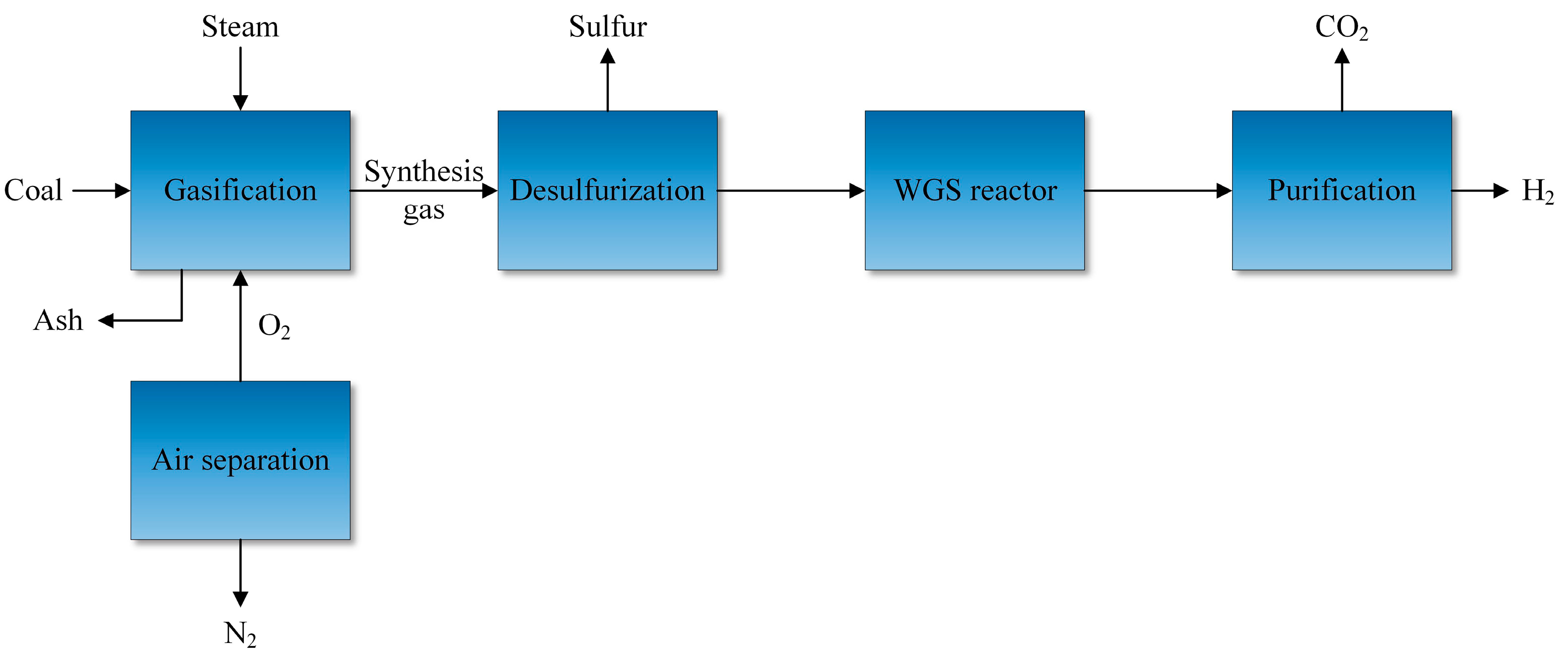
2.1.3. Gasification
2.2. Hydrogen Production from Biomass
2.2.1. Biomass Gasification
2.2.2. Biomass Pyrolysis
2.3. Hydrogen Production from Water
2.3.1. Alkaline Water Electrolysis
2.3.2. Proton Exchange Membrane Electrolysis
2.3.3. Solid Oxide Electrolysis
2.3.4. Photocatalytic Water Splitting
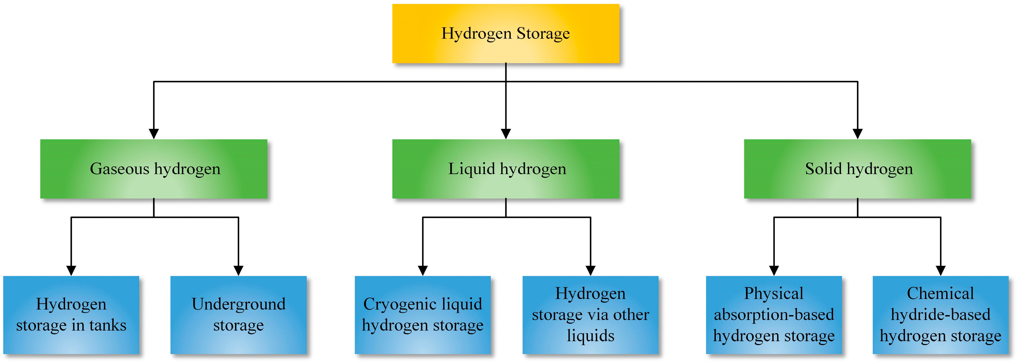
3. Hydrogen Storage
3.1. Gaseous Hydrogen Storage
3.1.1. Hydrogen Storage in Tanks
3.1.2. Underground Hydrogen Storage
3.2. Liquid Hydrogen Storage
3.2.1. Cryogenic Liquid Hydrogen Storage
3.2.2. Hydrogen Storage via Other Liquids
3.3. Solid Hydrogen Storage
3.3.1. Physical Adsorption-Based Hydrogen Storage
3.3.2. Chemical Hydride-Based Hydrogen Storage
4. Hydrogen Transportation and Delivery
4.1. Compressed Gaseous Tube Trailers
4.2. Cryogenic Liquid Tanker Trucks
4.3. Pipelines
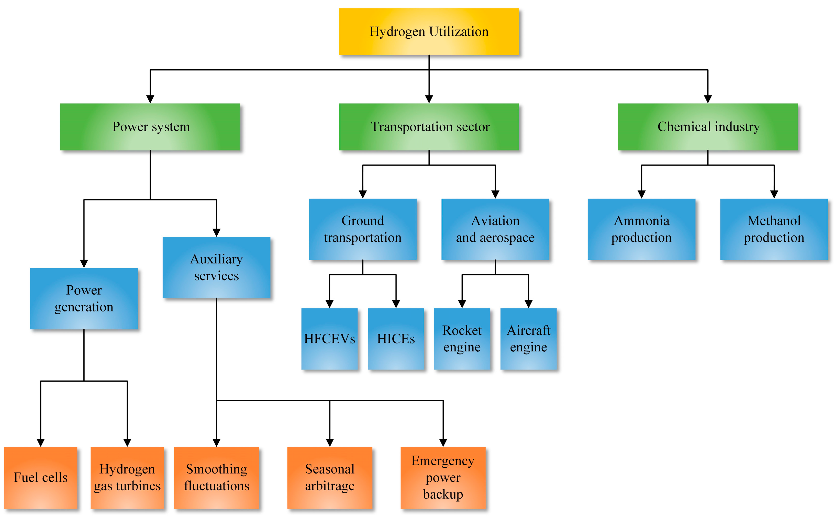
5. Hydrogen Utilization
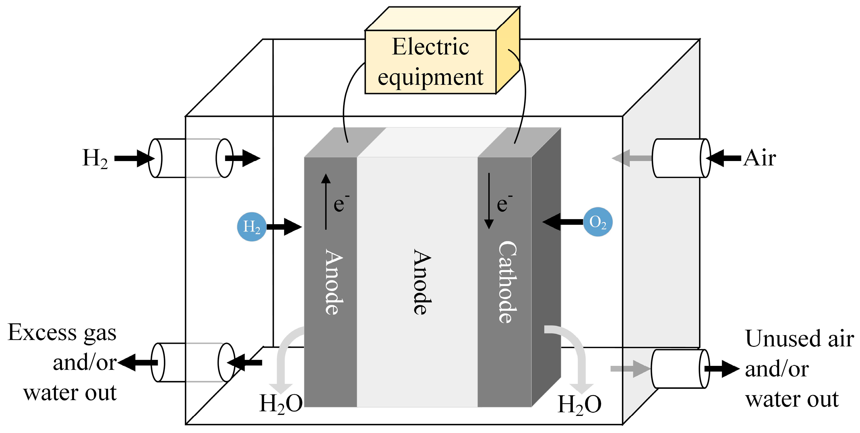
5.1. Hydrogen Employment in Power Systems
5.1.1. Hydrogen-Based Power Generation
5.1.2. Storing of Energy and Auxiliary Services
5.2. Hydrogen Employment in Transportation Sector
5.2.1. Hydrogen Employment in Ground Transportation
5.2.2. Hydrogen Employment in Aviation and Aerospace Sectors
5.3. Hydrogen Employment in Chemical Industry
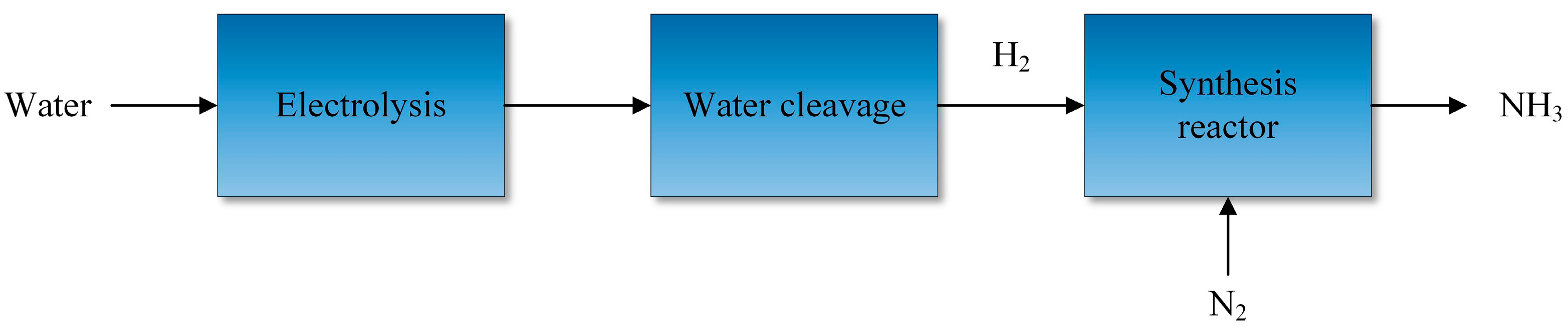
5.3.1. Hydrogen-Based Production of Ammonia
5.3.2. Hydrogen-Based Production of Methanol
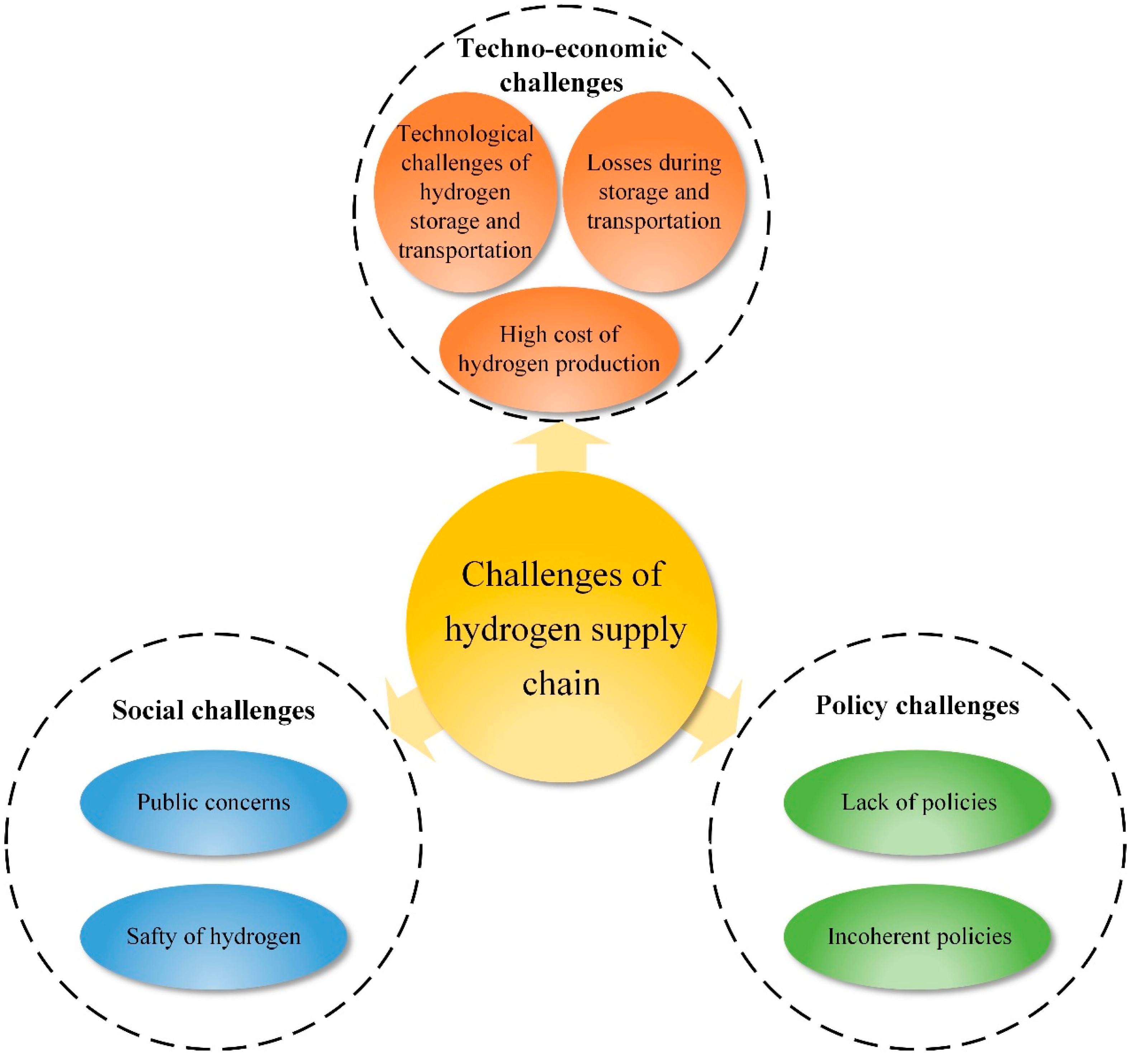
6. Challenges and Prospects of Future Hydrogen Supply Chain
7. Conclusions
- Currently, 96% of hydrogen is produced from fossil fuels, but producing hydrogen from fossil fuels can cause carbon emissions. In contrast, hydrogen production from biomass through gasification and pyrolysis offers lower carbon emissions. Water electrolysis and photocatalytic splitting of water are considered ideal methods for future green hydrogen production because only H2 and O2 are produced during the process. AWE is the most mature method for water electrolysis, while PEME and SOE have better efficiency and flexibility.
- Gaseous hydrogen storage is a low-cost and simple method for hydrogen storage. Due to the large capacity, underground hydrogen storage is an option for seasonal energy storage. Storing hydrogen in a liquid state can offer a high energy density, but the liquefaction process is technically difficult and expensive. An alternative is storing hydrogen in other liquids. Storing hydrogen in a solid state through physical adsorption or chemical reactions can achieve safe hydrogen storage and a high storage density.
- Regarding hydrogen transportation, compressed gaseous tube trailers, which have lower technical complexity, are suitable for short-distance transport of small quantities. Cryogenic liquid tanker trucks can transport more hydrogen per trip than gaseous tube trailers, making them suitable for medium-distance transportation of larger hydrogen quantities. Pipeline transportation of hydrogen involves higher capital costs but offers a large transportation capacity, making it suitable for long-distance transportation of large volumes of hydrogen.
- Hydrogen is a fuel and chemical feedstock with a wide range of applications. In the power systems sector, hydrogen can generate electricity through hydrogen fuel cells and hydrogen gas turbines. It can also serve as an energy storage method and provide auxiliary services for power systems, including smoothing fluctuations in renewable energy output, enabling seasonal energy storage arbitrage, and serving as an emergency backup power source. Liquid hydrogen has also been used as rocket fuel due to its high energy density, and researchers have made significant progress in exploring its potential as a fuel for cars and aircraft. Moreover, hydrogen has been utilized in the large-scale industrial production of ammonia and methanol.
Author Contributions
Funding
Institutional Review Board Statement
Informed Consent Statement
Data Availability Statement
Acknowledgments
Conflicts of Interest
References
- Qin, B.Y.; Li, H.Y.; Wang, Z.J.; Jiang, Y.; Lu, D.C.; Du, X.L.; Qian, Q.H. New framework of low-carbon city development of China: Underground space based integrated energy systems. Undergr. Space 2024, 14, 300–318. [Google Scholar] [CrossRef]
- Arani, A.A.K.; Karami, H.; Gharehpetian, G.B.; Hejazi, M.S.A. Review of Flywheel Energy Storage Systems structures and applications in power systems and microgrids. Renew. Sustain. Energy Rev. 2017, 69, 9–18. [Google Scholar] [CrossRef]
- Moreno, R.; Moreira, R.; Strbac, G. A MILP model for optimising multi-service portfolios of distributed energy storage. Appl. Energy 2015, 137, 554–566. [Google Scholar] [CrossRef]
- Midilli, A.; Ay, M.; Dincer, I.; Rosen, M.A. On hydrogen and hydrogen energy strategies: I: Current status and needs. Renew. Sustain. Energy Rev. 2005, 9, 255–271. [Google Scholar] [CrossRef]
- Li, H.; Qin, B.; Zhao, Y.; Li, F.; Wu, X.; Ding, T. Adaptively optimal energy management for integrated hydrogen energy systems. IET Gener. Transm. Dis. 2023, 17, 4750–4762. [Google Scholar] [CrossRef]
- Durbin, D.; Malardier-Jugroot, C. Review of hydrogen storage techniques for on board vehicle applications. Int. J. Hydrogen Energy 2013, 38, 14595–14617. [Google Scholar] [CrossRef]
- Schitea, D.; Deveci, M.; Iordache, M.; Bilgili, K.; Akyurt, I.Z.; Iordache, I. Hydrogen mobility roll-up site selection using intuitionistic fuzzy sets based WASPAS, COPRAS and EDAS. Int. J. Hydrogen Energy 2019, 44, 8585–8600. [Google Scholar] [CrossRef]
- Qin, B.Y.; Wang, H.Z.; Liao, Y.; Liu, D.; Li, F. Liquid hydrogen superconducting transmission based super energy pipeline for Pacific Rim in the context of global energy sustainable development. Int. J. Hydrogen Energy 2024, 56, 1391–1396. [Google Scholar] [CrossRef]
- Abe, J.O.; Popoola, A.; Ajenifuja, E.; Popoola, O.M. Hydrogen energy, economy and storage: Review and recommendation. Int. J. Hydrogen Energy 2019, 44, 15072–15086. [Google Scholar] [CrossRef]
- Abdin, Z.; Zafaranloo, A.; Rafiee, A.; Mérida, W.; Lipiński, W.; Khalilpour, K.R. Hydrogen as an energy vector. Renew. Sustain. Energy Rev. 2020, 120, 109620. [Google Scholar] [CrossRef]
- Osman, A.I.; Mehta, N.; Elgarahy, A.M.; Hefny, M.; Al-Hinai, A.; Al-Muhtaseb, A.H.; Rooney, D.W. Hydrogen production, storage, utilisation and environmental impacts: A review. Environ. Chem. Lett. 2022, 20, 153–188. [Google Scholar] [CrossRef]
- Momirlan, M.; Veziroglu, T.N. The properties of hydrogen as fuel tomorrow in sustainable energy system for a cleaner planet. Int. J. Hydrogen Energy 2005, 30, 795–802. [Google Scholar] [CrossRef]
- Wlodarczyk, R.; Kaleja, P. Modern hydrogen technologies in the face of climate change-analysis of strategy and development in polish conditions. Sustainability 2023, 15, 12891. [Google Scholar] [CrossRef]
- Ishaq, H.; Dincer, I.; Crawford, C. A review on hydrogen production and utilization: Challenges and opportunities. Int. J. Hydrogen Energy 2022, 47, 26238–26264. [Google Scholar] [CrossRef]
- Avargani, V.M.; Zendehboudi, S.; Saady, N.M.C.; Dusseault, M.B. A comprehensive review on hydrogen production and utilization in North America: Prospects and challenges. Energy Convers. Manag. 2022, 269, 34. [Google Scholar] [CrossRef]
- Bockris, J.O.M. A hydrogen economy. Science 1972, 176, 1323. [Google Scholar] [CrossRef]
- Ren, X.; Dong, L.; Xu, D.; Hu, B. Challenges towards hydrogen economy in China. Int. J. Hydrogen Energy 2020, 45, 34326–34345. [Google Scholar] [CrossRef]
- Sgarbossa, F.; Arena, S.; Tang, O.; Peron, M. Renewable hydrogen supply chains: A planning matrix and an agenda for future research. Int. J. Prod. Econ. 2023, 255, 108674. [Google Scholar] [CrossRef]
- Yu, J.; Han, Y.J.; Yang, H.; Lee, S.; Kim, G.; Lee, C. Promising technology analysis and patent roadmap development in the hydrogen supply chain. Sustainability 2022, 14, 14210. [Google Scholar] [CrossRef]
- Nicoletti, G.; Arcuri, N.; Nicoletti, G.; Bruno, R. A technical and environmental comparison between hydrogen and some fossil fuels. Energy Convers. Manag. 2015, 89, 205–213. [Google Scholar] [CrossRef]
- Pal, D.B.; Singh, A.; Bhatnagar, A. A review on biomass-based hydrogen production technologies. Int. J. Hydrogen Energy 2022, 47, 1461–1480. [Google Scholar] [CrossRef]
- Nikolaidis, P.; Poullikkas, A. A comparative overview of hydrogen production processes. Renew. Sustain. Energy Rev. 2017, 67, 597–611. [Google Scholar] [CrossRef]
- Scholz, W.H. Processes for industrial production of hydrogen and associated environmental effects. Gas Sep. Purif. 1993, 7, 131–139. [Google Scholar] [CrossRef]
- Chehade, A.M.E.H.; Daher, E.A.; Assaf, J.C.; Riachi, B.; Hamd, W. Simulation and optimization of hydrogen production by steam reforming of natural gas for refining and petrochemical demands in Lebanon. Int. J. Hydrogen Energy 2020, 45, 33235–33247. [Google Scholar] [CrossRef]
- Skataric, M.; Gajic, Z. Slow and fast dynamics of a natural gas hydrogen reformer. Int. J. Hydrogen Energy 2013, 38, 15173–15179. [Google Scholar] [CrossRef]
- Balat, M. Possible Methods for Hydrogen Production. Energy Sources Part A 2008, 31, 39–50. [Google Scholar] [CrossRef]
- Martínez, I.; Romano, M.C.; Chiesa, P.; Grasa, G.; Murillo, R. Hydrogen production through sorption enhanced steam reforming of natural gas: Thermodynamic plant assessment. Int. J. Hydrogen Energy 2013, 38, 15180–15199. [Google Scholar] [CrossRef]
- Anzelmo, B.; Wilcox, J.; Liguori, S. Hydrogen production via natural gas steam reforming in a Pd-Au membrane reactor. Comparison between methane and natural gas steam reforming reactions. J. Membr. Sci. 2018, 568, 113–120. [Google Scholar] [CrossRef]
- Al-Hamamre, Z.; Voß, S.; Trimis, D. Hydrogen production by thermal partial oxidation of hydrocarbon fuels in porous media based reformer. Int. J. Hydrogen Energy 2009, 34, 827–832. [Google Scholar] [CrossRef]
- Reyes, S.C.; Sinfelt, J.H.; Feeley, J.S. Evolution of processes for synthesis gas production: Recent developments in an old technology. Ind. Eng. Chem. Res. 2003, 42, 1588–1597. [Google Scholar] [CrossRef]
- Seçer, A.; Küçet, N.; Fakı, E.; Hasanoğlu, A. Comparison of co–gasification efficiencies of coal, lignocellulosic biomass and biomass hydrolysate for high yield hydrogen production. Int. J. Hydrogen Energy 2018, 43, 21269–21278. [Google Scholar] [CrossRef]
- Muresan, M.; Cormos, C.-C.; Agachi, P.-S. Techno-economical assessment of coal and biomass gasification-based hydrogen production supply chain system. Chem. Eng. Res. Des. 2013, 91, 1527–1541. [Google Scholar] [CrossRef]
- Demirbaş, A. Mechanisms of liquefaction and pyrolysis reactions of biomass. Energy Convers. Manag. 2000, 41, 633–646. [Google Scholar] [CrossRef]
- Palmer, C.; Bunyan, E.; Gelinas, J.; Gordon, M.J.; Metiu, H.; McFarland, E.W. CO2-free hydrogen production by catalytic pyrolysis of hydrocarbon feedstocks in molten Ni–Bi. Energy Fuels 2020, 34, 16073–16080. [Google Scholar] [CrossRef]
- Pinsky, R.; Sabharwall, P.; Hartvigsen, J.; O’Brien, J. Comparative review of hydrogen production technologies for nuclear hybrid energy systems. Prog. Nucl. Energy 2020, 123, 103317. [Google Scholar] [CrossRef]
- Angeli, S.D.; Monteleone, G.; Giaconia, A.; Lemonidou, A.A. State-of-the-art catalysts for CH4 steam reforming at low temperature. Int. J. Hydrogen Energy 2014, 39, 1979–1997. [Google Scholar] [CrossRef]
- Zhang, H.T.; Sun, Z.X.; Hu, Y.H. Steam reforming of methane: Current states of catalyst design and process upgrading. Renew. Sustain. Energy Rev. 2021, 149, 23. [Google Scholar] [CrossRef]
- Agrafiotis, C.; von Storch, H.; Roeb, M.; Sattler, C. Solar thermal reforming of methane feedstocks for hydrogen and syngas production—A review. Renew. Sustain. Energy Rev. 2014, 29, 656–682. [Google Scholar] [CrossRef]
- Simakov, D.S.; Wright, M.M.; Ahmed, S.; Mokheimer, E.M.; Román-Leshkov, Y. Solar thermal catalytic reforming of natural gas: A review on chemistry, catalysis and system design. Catal. Sci. Technol. 2015, 5, 1991–2016. [Google Scholar] [CrossRef]
- Zedtwitz, P.v.; Petrasch, J.; Trommer, D.; Steinfeld, A. Hydrogen production via the solar thermal decarbonization of fossil fuels. Solar Energy 2006, 80, 1333–1337. [Google Scholar] [CrossRef]
- Ghasemzadeh, K.; Harasi, J.N.; Amiri, T.Y.; Basile, A.; Iulianelli, A. Methanol steam reforming for hydrogen generation: A comparative modeling study between silica and Pd-based membrane reactors by CFD method. Fuel Process. Technol. 2020, 199, 8. [Google Scholar] [CrossRef]
- Xu, X.; Zhou, Q.; Yu, D. The future of hydrogen energy: Bio-hydrogen production technology. Int. J. Hydrogen Energy 2022, 47, 33677–33698. [Google Scholar] [CrossRef]
- York, A.P.; Xiao, T.; Green, M.L. Brief overview of the partial oxidation of methane to synthesis gas. Top. Catal. 2003, 22, 345–358. [Google Scholar] [CrossRef]
- Mujeebu, M.A. Hydrogen and syngas production by superadiabatic combustion–a review. Appl. Energy 2016, 173, 210–224. [Google Scholar] [CrossRef]
- Osman, A.I. Catalytic Hydrogen production from methane partial oxidation: Mechanism and kinetic study. Chem. Eng. Technol. 2020, 43, 641–648. [Google Scholar] [CrossRef]
- Tang, M.; Xu, L.; Fan, M. Progress in oxygen carrier development of methane-based chemical-looping reforming: A review. Appl. Energy 2015, 151, 143–156. [Google Scholar] [CrossRef]
- Liu, T.; Snyder, C.; Veser, G. Catalytic partial oxidation of methane: Is a distinction between direct and indirect pathways meaningful? Ind. Eng. Chem. Res. 2007, 46, 9045–9052. [Google Scholar] [CrossRef]
- Aasberg-Petersen, K.; Christensen, T.; Dybkjaer, I.; Sehested, J.; Østberg, M.; Coertzen, R.; Keyser, M.; Steynberg, A. Synthesis gas production for FT synthesis. Stud. Surf. Sci. Catal. 2004, 152, 258–405. [Google Scholar]
- Hosseini, S.E.; Wahid, M.A. Hydrogen production from renewable and sustainable energy resources: Promising green energy carrier for clean development. Renew. Sustain. Energy Rev. 2016, 57, 850–866. [Google Scholar] [CrossRef]
- Midilli, A.; Kucuk, H.; Topal, M.E.; Akbulut, U.; Dincer, I. A comprehensive review on hydrogen production from coal gasification: Challenges and Opportunities. Int. J. Hydrogen Energy 2021, 46, 25385–25412. [Google Scholar] [CrossRef]
- Karimi, F.; Khalilpour, R. Evolution of carbon capture and storage research: Trends of international collaborations and knowledge maps. Int. J. Green. Gas Control 2015, 37, 362–376. [Google Scholar] [CrossRef]
- Demirbaş, A. Biomass resource facilities and biomass conversion processing for fuels and chemicals. Energy Convers. Manag. 2001, 42, 1357–1378. [Google Scholar] [CrossRef]
- Zhang, Y.; Xu, P.; Liang, S.; Liu, B.; Shuai, Y.; Li, B. Exergy analysis of hydrogen production from steam gasification of biomass: A review. Int. J. Hydrogen Energy 2019, 44, 14290–14302. [Google Scholar] [CrossRef]
- Tezer, Ö.; Karabag, N.; Öngen, A.; Çolpan, C.; Ayol, A. Biomass gasification for sustainable energy production: A review. Int. J. Hydrogen Energy 2022, 47, 15419–15433. [Google Scholar] [CrossRef]
- Zhang, Y.; Gong, X.; Zhang, B.; Liu, W.; Xu, M. Potassium catalytic hydrogen production in sorption enhanced gasification of biomass with steam. Int. J. Hydrogen Energy 2014, 39, 4234–4243. [Google Scholar] [CrossRef]
- Ahmed, I.; Gupta, A. Syngas yield during pyrolysis and steam gasification of paper. Appl. Energy 2009, 86, 1813–1821. [Google Scholar] [CrossRef]
- Florin, N.H.; Harris, A.T. Enhanced hydrogen production from biomass with in situ carbon dioxide capture using calcium oxide sorbents. Chem. Eng. Sci. 2008, 63, 287–316. [Google Scholar] [CrossRef]
- Fahmy, T.Y.A.; Fahmy, Y.; Mobarak, F.; El-Sakhawy, M.; Abou-Zeid, R.E. Biomass pyrolysis: Past, present, and future. Environ. Dev. Sustain. 2020, 22, 17–32. [Google Scholar] [CrossRef]
- Barbarias, I.; Artetxe, M.; Lopez, G.; Arregi, A.; Santamaria, L.; Bilbao, J.; Olazar, M. Catalyst performance in the HDPE pyrolysis-reforming under reaction-regeneration cycles. Catalysts 2019, 9, 414. [Google Scholar] [CrossRef]
- Waheed, Q.M.; Wu, C.; Williams, P.T. Pyrolysis/reforming of rice husks with a Ni–dolomite catalyst: Influence of process conditions on syngas and hydrogen yield. J. Energy Inst. 2016, 89, 657–667. [Google Scholar] [CrossRef]
- Valle, B.; Aramburu, B.; Benito, P.L.; Bilbao, J.; Gayubo, A.G. Biomass to hydrogen-rich gas via steam reforming of raw bio-oil over Ni/La2O3-αAl2O3 catalyst: Effect of space-time and steam-to-carbon ratio. Fuel 2018, 216, 445–455. [Google Scholar] [CrossRef]
- Qinglan, H.; Chang, W.; Dingqiang, L.; Yao, W.; Dan, L.; Guiju, L. Production of hydrogen-rich gas from plant biomass by catalytic pyrolysis at low temperature. Int. J. Hydrogen Energy 2010, 35, 8884–8890. [Google Scholar] [CrossRef]
- Luo, S.; Fu, J.; Zhou, Y.; Yi, C. The production of hydrogen-rich gas by catalytic pyrolysis of biomass using waste heat from blast-furnace slag. Renew. Energy 2017, 101, 1030–1036. [Google Scholar] [CrossRef]
- Liu, G.Y.; Sheng, Y.; Ager, J.W.; Kraft, M.; Xu, R. Research advances towards large-scale solar hydrogen production from water. EnergyChem 2019, 1, 51. [Google Scholar] [CrossRef]
- Anwar, S.; Khan, F.; Zhang, Y.; Djire, A. Recent development in electrocatalysts for hydrogen production through water electrolysis. Int. J. Hydrogen Energy 2021, 46, 32284–32317. [Google Scholar] [CrossRef]
- Sapountzi, F.M.; Gracia, J.M.; Fredriksson, H.O.; Niemantsverdriet, J.H. Electrocatalysts for the generation of hydrogen, oxygen and synthesis gas. Prog. Energy Combust. Sci. 2017, 58, 1–35. [Google Scholar] [CrossRef]
- Cheng, X.; Li, Y.; Zheng, L.; Yan, Y.; Zhang, Y.; Chen, G.; Sun, S.; Zhang, J. Highly active, stable oxidized platinum clusters as electrocatalysts for the hydrogen evolution reaction. Energy Environ. Sci. 2017, 10, 2450–2458. [Google Scholar] [CrossRef]
- Zeng, K.; Zhang, D. Recent progress in alkaline water electrolysis for hydrogen production and applications. Prog. Energy Combust. Sci. 2010, 36, 307–326. [Google Scholar] [CrossRef]
- He, X.-D.; Xu, F.; Li, F.; Liu, L.; Wang, Y.; Deng, N.; Zhu, Y.-W.; He, J.-B. Composition-performance relationship of NixCuy nanoalloys as hydrogen evolution electrocatalyst. J. Electroanal. Chem. 2017, 799, 235–241. [Google Scholar] [CrossRef]
- Colli, A.N.; Girault, H.H.; Battistel, A. Non-precious electrodes for practical alkaline water electrolysis. Materials 2019, 12, 1336. [Google Scholar] [CrossRef] [PubMed]
- Marinkas, A.; Struźyńska-Piron, I.; Lee, Y.; Lim, A.; Park, H.S.; Jang, J.H.; Kim, H.-J.; Kim, J.; Maljusch, A.; Conradi, O. Anion-conductive membranes based on 2-mesityl-benzimidazolium functionalised poly (2,6-dimethyl-1,4-phenylene oxide) and their use in alkaline water electrolysis. Polymer 2018, 145, 242–251. [Google Scholar] [CrossRef]
- Sandeep, K.; Kamath, S.; Mistry, K.; Kumar, A.; Bhattacharya, S.; Bhanja, K.; Mohan, S. Experimental studies and modeling of advanced alkaline water electrolyser with porous nickel electrodes for hydrogen production. Int. J. Hydrogen Energy 2017, 42, 12094–12103. [Google Scholar] [CrossRef]
- Kumar, S.S.; Himabindu, V. Hydrogen production by PEM water electrolysis–A review. Mater. Sci. Energy Technol. 2019, 2, 442–454. [Google Scholar]
- Holladay, J.D.; Hu, J.; King, D.L.; Wang, Y. An overview of hydrogen production technologies. Catal. Today 2009, 139, 244–260. [Google Scholar] [CrossRef]
- Rozain, C.; Mayousse, E.; Guillet, N.; Millet, P. Influence of iridium oxide loadings on the performance of PEM water electrolysis cells: Part II–Advanced oxygen electrodes. Appl. Catal. B 2016, 182, 123–131. [Google Scholar] [CrossRef]
- Wang, S.; Lv, H.; Tang, F.M.; Sun, Y.W.; Ji, W.X.; Zhou, W.; Shen, X.J.; Zhang, C.M. Defect engineering assisted support effect: IrO2/N defective g-C3N4 composite as highly efficient anode catalyst in PEM water electrolysis. Chem. Eng. J. 2021, 419, 10. [Google Scholar] [CrossRef]
- Marshall, A.T.; Sunde, S.; Tsypkin, M.; Tunold, R. Performance of a PEM water electrolysis cell using IrxRuyTazO2 electrocatalysts for the oxygen evolution electrode. Int. J. Hydrogen Energy 2007, 32, 2320–2324. [Google Scholar] [CrossRef]
- Alia, S.M.; Shulda, S.; Ngo, C.; Pylypenko, S.; Pivovar, B.S. Iridium-based nanowires as highly active, oxygen evolution reaction electrocatalysts. ACS Catal. 2018, 8, 2111–2120. [Google Scholar] [CrossRef]
- Ju, H.; Badwal, S.; Giddey, S. A comprehensive review of carbon and hydrocarbon assisted water electrolysis for hydrogen production. Appl. Energy 2018, 231, 502–533. [Google Scholar] [CrossRef]
- Xu, W.; Scott, K. The effects of ionomer content on PEM water electrolyser membrane electrode assembly performance. Int. J. Hydrogen Energy 2010, 35, 12029–12037. [Google Scholar] [CrossRef]
- Brett, D.J.; Atkinson, A.; Brandon, N.P.; Skinner, S.J. Intermediate temperature solid oxide fuel cells. Chem. Soc. Rev. 2008, 37, 1568–1578. [Google Scholar] [CrossRef]
- Wolf, S.E.; Winterhalder, F.E.; Vibhu, V.; de Haart, L.G.J.; Guillon, O.; Eichel, R.A.; Menzler, N.H. Solid oxide electrolysis cells—Current material development and industrial application. J. Mater. Chem. A 2023, 11, 17977–18028. [Google Scholar] [CrossRef]
- Liu, J.; Wang, J.; Zhang, B.; Ruan, Y.; Lv, L.; Ji, X.; Xu, K.; Miao, L.; Jiang, J. Hierarchical NiCo2S4@ NiFe LDH heterostructures supported on nickel foam for enhanced overall-water-splitting activity. ACS Appl. Mater. Interfaces 2017, 9, 15364–15372. [Google Scholar] [CrossRef] [PubMed]
- Zheng, Y.; Wang, J.; Yu, B.; Zhang, W.; Chen, J.; Qiao, J.; Zhang, J. A review of high temperature co-electrolysis of H2O and CO2 to produce sustainable fuels using solid oxide electrolysis cells (SOECs): Advanced materials and technology. Chem. Soc. Rev. 2017, 46, 1427–1463. [Google Scholar] [CrossRef] [PubMed]
- Singh, V.; Muroyama, H.; Matsui, T.; Hashigami, S.; Inagaki, T.; Eguchi, K. Feasibility of alternative electrode materials for high temperature CO2 reduction on solid oxide electrolysis cell. J. Power Sources 2015, 293, 642–648. [Google Scholar] [CrossRef]
- Moçoteguy, P.; Brisse, A. A review and comprehensive analysis of degradation mechanisms of solid oxide electrolysis cells. Int. J. Hydrogen Energy 2013, 38, 15887–15902. [Google Scholar] [CrossRef]
- Wu, H.; Tan, H.L.; Toe, C.Y.; Scott, J.; Wang, L.Z.; Amal, R.; Ng, Y.H. Photocatalytic and Photoelectrochemical Systems: Similarities and Differences. Adv. Mater. 2020, 32, 21. [Google Scholar] [CrossRef] [PubMed]
- Bie, C.B.; Wang, L.X.; Yu, J.G. Challenges for photocatalytic overall water splitting. Chem 2022, 8, 1567–1574. [Google Scholar] [CrossRef]
- Zhang, S.; Wang, K.; Li, F.; Ho, S.H. Structure-mechanism relationship for enhancing photocatalytic H2 production. Int. J. Hydrogen Energy 2022, 47, 37517–37530. [Google Scholar] [CrossRef]
- Kahng, S.; Yoo, H.; Kim, J.H. Recent advances in earth-abundant photocatalyst materials for solar H2 production. Adv. Powder Technol. 2020, 31, 11–28. [Google Scholar] [CrossRef]
- Zhang, F.; Zhang, J.; Wang, H.; Li, J.; Liu, H.; Jin, X.; Wang, X.; Zhang, G. Single tungsten atom steered band-gap engineering for graphitic carbon nitride ultrathin nanosheets boosts visible-light photocatalytic H2 evolution. Chem. Eng. J. 2021, 424, 130004. [Google Scholar] [CrossRef]
- Zhan, X.; Zhao, Y.; Zhou, G.; Yu, J.; Wang, H.; Shi, H. Oxygen-containing groups and P doped porous carbon nitride nanosheets towards enhanced photocatalytic activity. Chemosphere 2022, 287, 132399. [Google Scholar] [CrossRef] [PubMed]
- Jiang, J.; Xiong, Z.; Wang, H.; Liao, G.; Bai, S.; Zou, J.; Wu, P.; Zhang, P.; Li, X. Sulfur-doped g-C3N4/g-C3N4 isotype step-scheme heterojunction for photocatalytic H2 evolution. J. Mater. Sci. Technol. 2022, 118, 15–24. [Google Scholar] [CrossRef]
- Wang, L.; Tang, G.; Liu, S.; Dong, H.; Liu, Q.; Sun, J.; Tang, H. Interfacial active-site-rich 0D Co3O4/1D TiO2 pn heterojunction for enhanced photocatalytic hydrogen evolution. Chem. Eng. J. 2022, 428, 131338. [Google Scholar] [CrossRef]
- Xue, Y.; Ji, Y.; Wang, X.; Wang, H.; Chen, X.; Zhang, X.; Tian, J. Heterostructuring noble-metal-free 1T’phase MoS2 with g-C3N4 hollow nanocages to improve the photocatalytic H2 evolution activity. Green Energy Environ. 2023, 8, 864–873. [Google Scholar] [CrossRef]
- Liang, Z.; Xue, Y.; Wang, X.; Zhang, X.; Tian, J. Structure engineering of 1T/2H multiphase MoS2 via oxygen incorporation over 2D layered porous g-C3N4 for remarkably enhanced photocatalytic hydrogen evolution. Mater. Today Nano 2022, 18, 100204. [Google Scholar] [CrossRef]
- Ursua, A.; Gandia, L.M.; Sanchis, P. Hydrogen production from water electrolysis: Current status and future trends. Proc. IEEE 2011, 100, 410–426. [Google Scholar] [CrossRef]
- Zheng, J.; Liu, X.; Xu, P.; Liu, P.; Zhao, Y.; Yang, J. Development of high pressure gaseous hydrogen storage technologies. Int. J. Hydrogen Energy 2012, 37, 1048–1057. [Google Scholar] [CrossRef]
- Okonkwo, P.C.; Belgacem, I.B.; Mansir, I.B.; Aliyu, M.; Emori, W.; Uzoma, P.C.; Beitelmal, W.H.; Akyüz, E.; Radwan, A.B.; Shakoor, R. A focused review of the hydrogen storage tank embrittlement mechanism process. Int. J. Hydrogen Energy 2023, 48, 12935–12948. [Google Scholar] [CrossRef]
- Jorgensen, S.W. Hydrogen storage tanks for vehicles: Recent progress and current status. Curr. Opin. Solid State Mater. Sci. 2011, 15, 39–43. [Google Scholar] [CrossRef]
- Li, H.; Qin, B.; Jiang, Y.; Zhao, Y.; Shi, W. Data-driven optimal scheduling for underground space based integrated hydrogen energy system. IET Renew. Power Gen. 2022, 16, 2521–2531. [Google Scholar] [CrossRef]
- Zivar, D.; Kumar, S.; Foroozesh, J. Underground hydrogen storage: A comprehensive review. Int. J. Hydrogen Energy 2021, 46, 23436–23462. [Google Scholar] [CrossRef]
- Tarkowski, R. Underground hydrogen storage: Characteristics and prospects. Renew. Sustain. Energy Rev. 2019, 105, 86–94. [Google Scholar] [CrossRef]
- Barison, E.; Donda, F.; Merson, B.; Le Gallo, Y.; Réveillère, A. An insight into underground hydrogen storage in Italy. Sustainability 2023, 15, 6866. [Google Scholar] [CrossRef]
- Bai, M.; Song, K.; Sun, Y.; He, M.; Li, Y.; Sun, J. An overview of hydrogen underground storage technology and prospects in China. J. Pet. Sci. Eng. 2014, 124, 132–136. [Google Scholar] [CrossRef]
- Sáinz-García, A.; Abarca, E.; Rubí, V.; Grandia, F. Assessment of feasible strategies for seasonal underground hydrogen storage in a saline aquifer. Int. J. Hydrogen Energy 2017, 42, 16657–16666. [Google Scholar] [CrossRef]
- Caglayan, D.G.; Weber, N.; Heinrichs, H.U.; Linssen, J.; Robinius, M.; Kukla, P.A.; Stolten, D. Technical potential of salt caverns for hydrogen storage in Europe. Int. J. Hydrogen Energy 2020, 45, 6793–6805. [Google Scholar] [CrossRef]
- Yue, M.L.; Lambert, H.; Pahon, E.; Roche, R.; Jemei, S.; Hissel, D. Hydrogen energy systems: A critical review of technologies, applications, trends and challenges. Renew. Sustain. Energy Rev. 2021, 146, 21. [Google Scholar] [CrossRef]
- Qiu, Y.; Yang, H.; Tong, L.; Wang, L. Research progress of cryogenic materials for storage and transportation of liquid hydrogen. Metals 2021, 11, 1101. [Google Scholar] [CrossRef]
- Ishimoto, Y.; Voldsund, M.; Nekså, P.; Roussanaly, S.; Berstad, D.; Gardarsdottir, S.O. Large-scale production and transport of hydrogen from Norway to Europe and Japan: Value chain analysis and comparison of liquid hydrogen and ammonia as energy carriers. Int. J. Hydrogen Energy 2020, 45, 32865–32883. [Google Scholar] [CrossRef]
- Schmidt, P.S.; Kerscher, M.; Klein, T.; Jander, J.H.; Bioucas, F.E.B.; Rüde, T.; Li, S.; Stadelmaier, M.; Hanyon, S.; Fathalla, R.R. Effect of the degree of hydrogenation on the viscosity, surface tension, and density of the liquid organic hydrogen carrier system based on diphenylmethane. Int. J. Hydrogen Energy 2022, 47, 6111–6130. [Google Scholar] [CrossRef]
- Ren, L.; Zhou, S.; Peng, T.; Ou, X. Greenhouse gas life cycle analysis of China’s fuel cell medium-and heavy-duty trucks under segmented usage scenarios and vehicle types. Energy 2022, 249, 123628. [Google Scholar] [CrossRef]
- Rusman, N.; Dahari, M. A review on the current progress of metal hydrides material for solid-state hydrogen storage applications. Int. J. Hydrogen Energy 2016, 41, 12108–12126. [Google Scholar] [CrossRef]
- Wang, T.; Aguey-Zinsou, K.-F. Controlling the growth of NaBH4 nanoparticles for hydrogen storage. Int. J. Hydrogen Energy 2020, 45, 2054–2067. [Google Scholar] [CrossRef]
- Dalebrook, A.F.; Gan, W.; Grasemann, M.; Moret, S.; Laurenczy, G. Hydrogen storage: Beyond conventional methods. Chem. Commun. 2013, 49, 8735–8751. [Google Scholar] [CrossRef]
- Schlapbach, L.; Züttel, A. Hydrogen-storage materials for mobile applications. Nature 2001, 414, 353–358. [Google Scholar] [CrossRef] [PubMed]
- Juneja, P.; Ghosh, S. Hydrogen storage using novel graphene-carbon nanotube hybrid. Mater. Today Proc. 2023, 76, 406–411. [Google Scholar] [CrossRef]
- Kostoglou, N.; Koczwara, C.; Stock, S.; Tampaxis, C.; Charalambopoulou, G.; Steriotis, T.; Paris, O.; Rebholz, C.; Mitterer, C. Nanoporous polymer-derived activated carbon for hydrogen adsorption and electrochemical energy storage. Chem. Eng. J. 2022, 427, 131730. [Google Scholar] [CrossRef]
- Tarhan, C.; Çil, M.A. A study on hydrogen, the clean energy of the future: Hydrogen storage methods. J. Energy Storage 2021, 40, 10. [Google Scholar] [CrossRef]
- Gray, E.M.; Webb, C.; Andrews, J.; Shabani, B.; Tsai, P.; Chan, S. Hydrogen storage for off-grid power supply. Int. J. Hydrogen Energy 2011, 36, 654–663. [Google Scholar] [CrossRef]
- Yu, H.; Cheng, Y.; Fu, Y.K.; Zhang, L.; Guo, S.Y.; Li, Y.; Zhang, W.; Han, S.M. Remarkable hydrogen properties of MgH2 via combination of an in-situ formed amorphous carbon. Int. J. Hydrogen Energy 2022, 47, 29358–29370. [Google Scholar] [CrossRef]
- Li, X.J.; Fu, Y.K.; Xie, Y.C.; Cong, L.; Yu, H.; Zhang, L.; Li, Y.; Han, S. Effect of Ni/tubular g-C3N4 on hydrogen storage properties of MgH2. Int. J. Hydrogen Energy 2021, 46, 33186–33196. [Google Scholar] [CrossRef]
- Ding, X.; Chen, R.R.; Chen, X.Y.; Cao, W.C.; Su, Y.Q.; Ding, H.S.; Guo, J.J. Formation of Mg2Ni/Cu phase and de-/hydrogenation behavior of Mg91Ni9-xCux alloy at moderate temperatures. Renew. Energy 2020, 166, 81–90. [Google Scholar] [CrossRef]
- Dangwal, S.; Edalati, K. Significance of interphase boundaries on activation of high-entropy alloys for room-temperature hydrogen storage. Int. J. Hydrogen Energy 2024, 50, 626–636. [Google Scholar] [CrossRef]
- Wu, S.P.; Chen, Y.P.; Kang, W.L.; Cai, X.L.; Zhou, L. Hydrogen storage properties of MgTiVZrNb high-entropy alloy and its catalytic effect upon hydrogen storage in Mg. Int. J. Hydrogen Energy 2024, 50, 1113–1128. [Google Scholar] [CrossRef]
- Ma, X.F.; Ding, X.; Chen, R.R.; Cao, W.C.; Song, Q. Study on hydrogen storage property of (ZrTiVFe)xAly high-entropy alloys by modifying Al content. Int. J. Hydrogen Energy 2022, 47, 8409–8418. [Google Scholar] [CrossRef]
- Ferraz, M.B.; Botta, W.J.; Zepon, G. Synthesis, characterization and first hydrogen absorption/desorption of the Mg35Al15Ti25V10Zn15 high entropy alloy. Int. J. Hydrogen Energy 2022, 47, 22881–22892. [Google Scholar] [CrossRef]
- Chen, W.; You, L.; Xia, G.; Yu, X. A balance between catalysis and nanoconfinement towards enhanced hydrogen storage performance of NaAlH4. J. Mater. Sci. Technol. 2021, 79, 205–211. [Google Scholar] [CrossRef]
- Sazelee, N.A.; Ismail, M. Recent advances in catalyst-enhanced LiAlH4 for solid-state hydrogen storage: A review. Int. J. Hydrogen Energy 2021, 46, 9123–9141. [Google Scholar] [CrossRef]
- Tayarani, H.; Ramji, A. Life cycle assessment of hydrogen transportation pathways via pipelines and truck trailers: Implications as a low carbon fuel. Sustainability 2022, 14, 12510. [Google Scholar] [CrossRef]
- Faye, O.; Szpunar, J.; Eduok, U. A critical review on the current technologies for the generation, storage, and transportation of hydrogen. Int. J. Hydrogen Energy 2022, 47, 13771–13802. [Google Scholar] [CrossRef]
- Weisberg, A.H.; Aceves, S.M.; Espinosa-Loza, F.; Ledesma-Orozco, E.; Myers, B. Delivery of cold hydrogen in glass fiber composite pressure vessels. Int. J. Hydrogen Energy 2009, 34, 9773–9780. [Google Scholar] [CrossRef]
- Rödl, A.; Wulf, C.; Kaltschmitt, M. Hydrogen Supply Chains, 3rd ed.; Elsevier: Amsterdam, The Netherlands, 2018; pp. 81–109. [Google Scholar]
- Demir, M.E.; Dincer, I. Cost assessment and evaluation of various hydrogen delivery scenarios. Int. J. Hydrogen Energy 2018, 43, 10420–10430. [Google Scholar] [CrossRef]
- Gerboni, R. Compendium of Hydrogen Energy, 3rd ed.; Elsevier: Amsterdam, The Netherlands, 2016; pp. 283–299. [Google Scholar]
- Razi, F.; Dincer, I. Challenges opportunities and future directions in hydrogen sector development in Canada. Int. J. Hydrogen Energy 2022, 47, 9083–9102. [Google Scholar] [CrossRef]
- Cheng, W.; Cheng, Y.F. A techno-economic study of the strategy for hydrogen transport by pipelines in Canada. J. Pipeline Sci. Eng. 2023, 3, 100112. [Google Scholar] [CrossRef]
- Reuß, M.; Grube, T.; Robinius, M.; Preuster, P.; Wasserscheid, P.; Stolten, D. Seasonal storage and alternative carriers: A flexible hydrogen supply chain model. Appl. Energy 2017, 200, 290–302. [Google Scholar] [CrossRef]
- Moradi, R.; Groth, K.M. Hydrogen storage and delivery: Review of the state of the art technologies and risk and reliability analysis. Int. J. Hydrogen Energy 2019, 44, 12254–12269. [Google Scholar] [CrossRef]
- Lisowski, E.; Lisowski, F. Study on thermal insulation of liquefied natural gas cryogenic road tanker. Therm. Sci. 2019, 23, 1381–1391. [Google Scholar] [CrossRef]
- Ziliang, L.; Sijiang, X.; Jingyang, Z. Comparative analysis of hydrogen pipeline and natural gas pipeline. Press. Vessel. Technol. 2020, 37, 56–63. [Google Scholar]
- Sun, Y.H.; Cheng, Y.F. Hydrogen-induced degradation of high-strength steel pipeline welds: A critical review. Eng. Fail. Anal. 2022, 133, 22. [Google Scholar] [CrossRef]
- Erdener, B.C.; Sergi, B.; Guerra, O.J.; Chueca, A.L.; Pambour, K.; Brancucci, C.; Hodge, B.M. A review of technical and regulatory limits for hydrogen blending in natural gas pipelines. Int. J. Hydrogen Energy 2023, 48, 5595–5617. [Google Scholar] [CrossRef]
- Cinti, G.; Bidini, G.; Hemmes, K. Comparison of the solid oxide fuel cell system for micro CHP using natural gas with a system using a mixture of natural gas and hydrogen. Appl. Energy 2019, 238, 69–77. [Google Scholar] [CrossRef]
- Isaac, T. HyDeploy: The UK’s first hydrogen blending deployment project. Clean Energy 2019, 3, 114–125. [Google Scholar] [CrossRef]
- Stansberry, J.M.; Brouwer, J. Experimental dynamic dispatch of a 60 kW proton exchange membrane electrolyzer in power-to-gas application. Int. J. Hydrogen Energy 2020, 45, 9305–9316. [Google Scholar] [CrossRef]
- Elmer, T.; Worall, M.; Wu, S.; Riffat, S.B. Fuel cell technology for domestic built environment applications: State of-the-art review. Renew. Sustain. Energy Rev. 2015, 42, 913–931. [Google Scholar] [CrossRef]
- Sharaf, O.Z.; Orhan, M.F. An overview of fuel cell technology: Fundamentals and applications. Renew. Sustain. Energy Rev. 2014, 32, 810–853. [Google Scholar] [CrossRef]
- Mekhilef, S.; Saidur, R.; Safari, A. Comparative study of different fuel cell technologies. Renew. Sustain. Energy Rev. 2012, 16, 981–989. [Google Scholar] [CrossRef]
- Zhang, X.; Chan, S.H.; Ho, H.K.; Tan, S.-C.; Li, M.; Li, G.; Li, J.; Feng, Z. Towards a smart energy network: The roles of fuel/electrolysis cells and technological perspectives. Int. J. Hydrogen Energy 2015, 40, 6866–6919. [Google Scholar] [CrossRef]
- Shen, Y.K.; Li, X.Q.; Wang, N.; Li, L.; Hoseyni, A. Introducing and investigation of a pumped hydro-compressed air storage based on wind turbine and alkaline fuel cell and electrolyzer. Sustain. Energy Technol. Assess. 2021, 47, 14. [Google Scholar] [CrossRef]
- Bidault, F.; Brett, D.; Middleton, P.; Brandon, N. Review of gas diffusion cathodes for alkaline fuel cells. J. Power Sources 2009, 187, 39–48. [Google Scholar] [CrossRef]
- Gülzow, E. Alkaline fuel cells: A critical view. J. Power Sources 1996, 61, 99–104. [Google Scholar] [CrossRef]
- Wang, Y.; Chen, K.S.; Mishler, J.; Cho, S.C.; Adroher, X.C. A review of polymer electrolyte membrane fuel cells: Technology, applications, and needs on fundamental research. Appl. Energy 2011, 88, 981–1007. [Google Scholar] [CrossRef]
- Authayanun, S.; Im-Orb, K.; Arpornwichanop, A. A review of the development of high temperature proton exchange membrane fuel cells. Chin. J. Catal. 2015, 36, 473–483. [Google Scholar] [CrossRef]
- Etesami, M.; Mehdipour-Ataei, S.; Somwangthanaroj, A.; Kheawhom, S. Recent progress of electrocatalysts for hydrogen proton exchange membrane fuel cells. Int. J. Hydrogen Energy 2022, 47, 41956–41973. [Google Scholar] [CrossRef]
- Choudhury, A.; Chandra, H.; Arora, A. Application of solid oxide fuel cell technology for power generation—A review. Renew. Sustain. Energy Rev. 2013, 20, 430–442. [Google Scholar] [CrossRef]
- Patakangas, J.; Ma, Y.; Jing, Y.; Lund, P. Review and analysis of characterization methods and ionic conductivities for low-temperature solid oxide fuel cells (LT-SOFC). J. Power Sources 2014, 263, 315–331. [Google Scholar] [CrossRef]
- Emadi, M.A.; Chitgar, N.; Oyewunmi, O.A.; Markides, C.N. Working-fluid selection and thermoeconomic optimisation of a combined cycle cogeneration dual-loop organic Rankine cycle (ORC) system for solid oxide fuel cell (SOFC) waste-heat recovery. Appl. Energy 2020, 261, 20. [Google Scholar] [CrossRef]
- Dinesh, K.R.; Jiang, X.; Kirkpatrick, M.; Malalasekera, W. Combustion characteristics of H2/N2 and H2/CO syngas nonpremixed flames. Int. J. Hydrogen Energy 2012, 37, 16186–16200. [Google Scholar] [CrossRef]
- Ourahou, M.; Ayrir, W.; Hassouni, B.E.; Haddi, A. Review on smart grid control and reliability in presence of renewable energies: Challenges and prospects. Math. Comput. Simulat. 2020, 167, 19–31. [Google Scholar] [CrossRef]
- Basit, M.A.; Dilshad, S.; Badar, R.; Sami ur Rehman, S.M. Limitations, challenges, and solution approaches in grid-connected renewable energy systems. Int. J. Energy Res. 2020, 44, 4132–4162. [Google Scholar] [CrossRef]
- Wang, Y.; Pang, Y.; Xu, H.; Martinez, A.; Chen, K.S. PEM Fuel cell and electrolysis cell technologies and hydrogen infrastructure development–a review. Energy Environ. Sci. 2022, 15, 2288–2328. [Google Scholar] [CrossRef]
- Bird, L.; Lew, D.; Milligan, M.; Carlini, E.M.; Estanqueiro, A.; Flynn, D.; Gomez-Lazaro, E.; Holttinen, H.; Menemenlis, N.; Orths, A. Wind and solar energy curtailment: A review of international experience. Renew. Sustain. Energy Rev. 2016, 65, 577–586. [Google Scholar] [CrossRef]
- Larscheid, P.; Lück, L.; Moser, A. Potential of new business models for grid integrated water electrolysis. Renew. Energy 2018, 125, 599–608. [Google Scholar] [CrossRef]
- Bocklisch, T. Hybrid energy storage approach for renewable energy applications. J. Energy Storage 2016, 8, 311–319. [Google Scholar] [CrossRef]
- Zhang, Z.; Nagasaki, Y.; Miyagi, D.; Tsuda, M.; Komagome, T.; Tsukada, K.; Hamajima, T.; Ayakawa, H.; Ishii, Y.; Yonekura, D. Stored energy control for long-term continuous operation of an electric and hydrogen hybrid energy storage system for emergency power supply and solar power fluctuation compensation. Int. J. Hydrogen Energy 2019, 44, 8403–8414. [Google Scholar] [CrossRef]
- Agaton, C.B.; Batac, K.I.T.; Reyes Jr, E.M. Prospects and challenges for green hydrogen production and utilization in the Philippines. Int. J. Hydrogen Energy 2022, 47, 17859–17870. [Google Scholar] [CrossRef]
- Hassan, Q.; Azzawi, I.D.J.; Sameen, A.Z.; Salman, H.M. Hydrogen fuel cell vehicles: Opportunities and challenges. Sustainability 2023, 15, 11501. [Google Scholar] [CrossRef]
- Wang, B.; Li, Z.; Zhou, J.; Cong, Y.; Li, Z. Technological-economic assessment and optimization of hydrogen-based transportation systems in China: A life cycle perspective. Int. J. Hydrogen Energy 2023, 48, 12155–12167. [Google Scholar] [CrossRef]
- Krebs, S.; Biet, C. Predictive model of a premixed, lean hydrogen combustion for internal combustion engines. Transp. Eng. 2021, 5, 100086. [Google Scholar] [CrossRef]
- Li, J.; Huang, H.; Kobayashi, N.; He, Z.; Nagai, Y. Study on using hydrogen and ammonia as fuels: Combustion characteristics and NOx formation. Int. J. Energy Res. 2014, 38, 1214–1223. [Google Scholar] [CrossRef]
- Gao, J.B.; Wang, X.C.; Song, P.P.; Tian, G.H.; Ma, C.C. Review of the backfire occurrences and control strategies for port hydrogen injection internal combustion engines. Fuel 2022, 307, 15. [Google Scholar] [CrossRef]
- Wei, S.M.; Yu, M.G.; Pei, B.; Ma, Z.H.; Li, S.L.; Kang, Y.X. Effect of hydrogen enrichment on the laminar burning characteristics of dimethyl-ether/methane fuel: Experimental and modeling study. Fuel 2021, 305, 13. [Google Scholar] [CrossRef]
- Johari, A.; Singh, S.; Vidya, S. Engine performance analysis for diesel engine using hydrogen as an alternative fuel. Mater. Today Proc. 2022, 56, 342–346. [Google Scholar] [CrossRef]
- Verhelst, S. Recent progress in the use of hydrogen as a fuel for internal combustion engines. Int. J. Hydrogen Energy 2014, 39, 1071–1085. [Google Scholar] [CrossRef]
- Cecere, D.; Giacomazzi, E.; Ingenito, A. A review on hydrogen industrial aerospace applications. Int. J. Hydrogen Energy 2014, 39, 10731–10747. [Google Scholar] [CrossRef]
- Tzanetis, K.F.; Posada, J.A.; Ramirez, A. Analysis of biomass hydrothermal liquefaction and biocrude-oil upgrading for renewable jet fuel production: The impact of reaction conditions on production costs and GHG emissions performance. Renew. Energy 2017, 113, 1388–1398. [Google Scholar] [CrossRef]
- Gomez, A.; Smith, H. Liquid hydrogen fuel tanks for commercial aviation: Structural sizing and stress analysis. Aerosp. Sci. Technol. 2019, 95, 12. [Google Scholar] [CrossRef]
- Baroutaji, A.; Wilberforce, T.; Ramadan, M.; Olabi, A.G. Comprehensive investigation on hydrogen and fuel cell technology in the aviation and aerospace sectors. Renew. Sustain. Energy Rev. 2019, 106, 31–40. [Google Scholar] [CrossRef]
- Arora, P.; Sharma, I.; Hoadley, A.; Mahajani, S.; Ganesh, A. Remote, small-scale, ‘greener’ routes of ammonia production. J. Clean. Prod. 2018, 199, 177–192. [Google Scholar] [CrossRef]
- Ausfelder, F.; Bazzanella, A. Hydrogen Science and Engineering: Materials, Processes, Systems and Technology, 3rd ed.; Wiley: Hoboken, NJ, USA, 2016; pp. 19–40. [Google Scholar]
- Olah, G.A.; Prakash, G.S.; Goeppert, A. Anthropogenic chemical carbon cycle for a sustainable future. J. Am. Chem. Soc. 2011, 133, 12881–12898. [Google Scholar] [CrossRef] [PubMed]
- Bisotti, F.; Fedeli, M.; Prifti, K.; Galeazzi, A.; Dell’Angelo, A.; Barbieri, M.; Pirola, C.; Bozzano, G.; Manenti, F. Century of technology trends in methanol synthesis: Any need for kinetics refitting? Ind. Eng. Chem. Res. 2021, 60, 16032–16053. [Google Scholar] [CrossRef]
- Milani, D.; Khalilpour, R.; Zahedi, G.; Abbas, A. A model-based analysis of CO2 utilization in methanol synthesis plant. J. CO2 Util. 2015, 10, 12–22. [Google Scholar] [CrossRef]
- Ju, H.; Kaur, G.; Kulkarni, A.P.; Giddey, S. Challenges and trends in developing technology for electrochemically reducing CO2 in solid polymer electrolyte membrane reactors. J. CO2 Util. 2019, 32, 178–186. [Google Scholar] [CrossRef]
- Fernández-González, J.; Rumayor, M.; Domínguez-Ramos, A.; Irabien, A. Hydrogen utilization in the sustainable manufacture of CO2-based methanol. Ind. Eng. Chem. Res. 2022, 61, 6163–6172. [Google Scholar] [CrossRef]
- Han, W.; Zhang, G.; Xiao, J.; Bénard, P.; Chahine, R. Demonstrations and marketing strategies of hydrogen fuel cell vehicles in China. Int. J. Hydrogen Energy 2014, 39, 13859–13872. [Google Scholar] [CrossRef]


| Fuel | HHV (kJ/g) | LHV (kJ/g) |
|---|---|---|
| Hydrogen | 141.9 | 119.9 |
| Methane | 55.5 | 50.0 |
| Gasoline | 47.5 | 44.5 |
| Diesel | 44.8 | 42.5 |
| Methanol | 20.0 | 18.1 |
| Electrolysis Technique | Electrolyte | Operating Temperature | Electrolytic Efficiency | Advantage | Disadvantage | Maturity |
|---|---|---|---|---|---|---|
| AWE | Alkaline aqueous solution | 70~90 °C | 60~75% | Mature technology, low cost | Corrosion pollution problem, high maintenance cost, long response time | Commercial maturity |
| PEME | Proton exchange membrane | 50~80 °C | 70~90% | Safe and pollution-free, high flexibility, adapt to fluctuating power supply | Immature technology, high cost | Preliminary commercialization |
| SOE | Solid oxide | 500~1000 °C | 85~100% | Safe and pollution-free, high efficiency | High working temperature, immature technology | Research and development |
| Hydrides | Hydrogen Storage Capacities (wt%) | Temperature (K) | Ref. |
|---|---|---|---|
| MgH2-CPF | 5.67 | 623 | [121] |
| MgH2–Ni/TCN | 5.24 | 423 | [122] |
| Mg91Ni6Cu3 | 5.6 | 448 | [123] |
| TiV1.5ZrCr0.5MnFeNi | 1.6 | 673 | [124] |
| Mg10Ti30V25Zr10Nb25 | 1.19 | 418 | [125] |
| (ZrTiVFe)90Al10 | 1.3 | 298 | [126] |
| Mg35Al15Ti25V10Zn15 | 2.5 | 375 | [127] |
| Hydrogen Transportation Option | Capacity | Transport Distance | Energy Loss | Fixed Costs | Variable Costs | Deployment Phase |
|---|---|---|---|---|---|---|
| Hydrogen pipelines | H | H | L | H | L | Medium to long term |
| Gaseous tube trailers | L | L | L | L | H | Near term |
| Liquefied tankers | M | H | H | M | M | Medium to long term |
| Tank Type | Volume (L) | Pressure (bar) | H2 Capacity (kg) | Tank Tare Weight (kg) |
|---|---|---|---|---|
| Steel cylinder container (SC) | 23,800 | 200 | 400 | 26,298 |
| Steel tubes (STs) | 19,292 | 200 | 324 | 27,254 |
| Composite super light container (CC) | 45,500 | 250 | 957 | 18,854 |
| Composite trailer (CT) | 44,200 | 250 | 979 | 21,810 |
| Fuel Cell Type | Operating Temperature (°C) | System Output (kW) | Electrical Efficiency (%) | Combined Heat and Power (CHP) Efficiency | Advantages |
|---|---|---|---|---|---|
| PAFC | 150–200 | 50–1000 | >40 | >85 | Higher overall efficiency with CHP, increased tolerance to impurities in hydrogen |
| AFC | 90–100 | 10–100 | 60 | >80 | Cathode reaction faster in alkaline electrolyte leads to higher performance, can use a variety of catalysts |
| PEMFC | 50–1000 | <1–250 | 53–58 | 70–90 | Solid electrolyte reduces corrosion and electrolyte management problems, low temperature, quick start-up |
| SOFC | 600–1000 | <1–3000 | 35–43 | <90 | High efficiency, fuel flexibility, solid electrolyte reduces electrolyte management problems, suitable for CHP |
| MCFC | 600–700 | <1–1000 | 45–47 | >80 | High efficiency, fuel flexibility, can use a variety of catalysts, suitable for CHP |
Disclaimer/Publisher’s Note: The statements, opinions and data contained in all publications are solely those of the individual author(s) and contributor(s) and not of MDPI and/or the editor(s). MDPI and/or the editor(s) disclaim responsibility for any injury to people or property resulting from any ideas, methods, instructions or products referred to in the content. |
© 2024 by the authors. Licensee MDPI, Basel, Switzerland. This article is an open access article distributed under the terms and conditions of the Creative Commons Attribution (CC BY) license (https://creativecommons.org/licenses/by/4.0/).
Share and Cite
Li, F.; Liu, D.; Sun, K.; Yang, S.; Peng, F.; Zhang, K.; Guo, G.; Si, Y. Towards a Future Hydrogen Supply Chain: A Review of Technologies and Challenges. Sustainability 2024, 16, 1890. https://doi.org/10.3390/su16051890
Li F, Liu D, Sun K, Yang S, Peng F, Zhang K, Guo G, Si Y. Towards a Future Hydrogen Supply Chain: A Review of Technologies and Challenges. Sustainability. 2024; 16(5):1890. https://doi.org/10.3390/su16051890
Chicago/Turabian StyleLi, Fan, Dong Liu, Ke Sun, Songheng Yang, Fangzheng Peng, Kexin Zhang, Guodong Guo, and Yuan Si. 2024. "Towards a Future Hydrogen Supply Chain: A Review of Technologies and Challenges" Sustainability 16, no. 5: 1890. https://doi.org/10.3390/su16051890
APA StyleLi, F., Liu, D., Sun, K., Yang, S., Peng, F., Zhang, K., Guo, G., & Si, Y. (2024). Towards a Future Hydrogen Supply Chain: A Review of Technologies and Challenges. Sustainability, 16(5), 1890. https://doi.org/10.3390/su16051890