Article

The Strategy of Continuous Commutation Failure Suppression by Combining Turn-off Angle Compensation and Dynamic Nonlinear VDCOL

Key Laboratory of Modern Power System Simulation Control and New Green Energy Technology, Ministry of Education (Northeast Electric Power University), Jilin 132012, China
*
Author to whom correspondence should be addressed.
Sustainability 2024, 16(5), 2145; https://doi.org/10.3390/su16052145
Submission received: 1 February 2024 / Revised: 26 February 2024 / Accepted: 29 February 2024 / Published: 5 March 2024

Abstract

:
In recent years, with the continuous growth in China’s economy, the continuous advancement of urbanization and industrialization, the contradiction between rapid economic development and the continuous reduction in traditional fossil energy reserves such as coal, oil, and natural gas, the continuous aggravation of environmental pollution has become increasingly prominent. In this era, clean energy power generation technologies such as hydropower, wind power, and solar power generation, which have the advantages of renewability, environmental protection, and economy, have developed rapidly. However, wind and photovoltaic power plants are often located in remote areas, which means significant losses in the transmission process. High-voltage direct current (HVDC) transmission technology becomes the best choice to solve this problem. The HVDC transmission system based on a grid commutator is widely used in China’s AC-DC hybrid power grid. When an AC fault occurs on the inverter side, the line-commutated converter high-voltage direct current (LCC-HVDC) system is more prone to continuous commutation failure, which brings serious harm to system operation. To better suppress the problem of continuous commutation failure on the contravariant side, this paper analyzes the mechanism of continuous commutation failure from multiple angles. The DC current command sensitivity of a voltage-dependent current order limiter (VDCOL) in the LCC-HVDC system is low, which will lead to different degrees of continuous commutation failure. In addition, the rapid rise in DC current and the drop in commutation voltage during the fault will cause the turn-off angle to drop, and the probability of continuous commutation failure of the system will increase significantly. Based on the above theoretical analysis, a new control strategy combining the dynamic compensation of the turn-off angle of a virtual inductor and the suppression of continuous commutation failure by dynamic nonlinear VDCOL is proposed. A dynamic nonlinear VDCOL control strategy is proposed for the low sensitivity of current command adjustment under conventional VDCOL control. Secondly, two concepts of virtual inductance and DC current change rate are introduced, and a control strategy based on virtual inductance is proposed to comprehensively ensure that the switching angle has sufficient commutation margin during fault recovery. Finally, based on the CIGRE standard test model in PSCAD/EMTDC, the accuracy of the correlation mechanism analysis and the effectiveness of the suppression method are verified.

1. Introduction

In the context of the rapid development of the global economy and the increasing population, the increasing demand for resources and the sustainable use of resources have become an important global issue. We have always relied on fossil fuels to meet our energy needs, but there are limits to how much can be obtained. In recent years, the development of new energy has exerted a great impact on the sustainable development of human society and alleviated the problem of energy sustainability to a certain extent [1,2]. However, wind and photovoltaic power plants are often located in remote areas, which means significant losses in the transmission process. China is a big country with a large population, so it is urgent to develop new energy to alleviate the increasingly tight energy problem. As China accelerates the transformation of its energy system to conservation and efficiency and its energy structure to a green and low-carbon transformation strategy, renewable energy sources such as wind power and solar power are developing rapidly. While energy bases are mostly located in the west and north (for example, 80% of coal resources are distributed in the northwest and 80% of hydropower resources are concentrated in the southwest), China’s energy demand center is located in the economically developed eastern provinces, whose electric energy consumption accounts for more than half of the national power generation, thus forming a pattern of inverse distribution of energy centers and load centers in China [3]. In this context, the DC transmission technology, which is suitable for large-capacity, long-distance energy transmission and makes it easy to connect new energy to the grid, has become a research hotspot in the industry. HVDC transmission technology has become the best choice to solve this problem. The line-commutated converter high-voltage direct current (LCC-HVDC) system has the advantages of large capacity, long distance, low active power loss, etc. At present, more than ten LCC-HVDC projects have been completed and put into operation in China, forming an increasingly perfect AC-DC hybrid power grid, and some areas have formed a new pattern of DC multi-feed. It plays a crucial role in China’s power grid architecture [4,5].
The LCC-HVDC system takes the thyristor without self-shutdown function as the core device. When the system fails, it risks continuous commutation failure. If appropriate and timely control measures are not taken, subsequent commutation failures can occur easily, which will cause repeated power shocks to the AC system, resulting in the locking of the converter station. When the carrying capacity of the AC system is weak, the locking of the converter station may cause the transfer of active power flow, which makes the protection of the AC transmission line in normal operation malfunction, resulting in cascading faults. At the same time, the locking of the converter station causes a power imbalance in the power grid at the sending and receiving ends, which may force the system to switch the machine to reduce the load or even automatically detrain [6]. To ensure the system’s safe and stable operation, it is crucial to investigate an effective method for suppressing these failures in communication.
Because of the problem of continuous commutation failure of the LCC-HVDC system, many theoretical analyses and experimental verifications have been carried out by scholars in China and abroad, and great results have been achieved. To be clear, faults in the inverter-side AC system are mostly caused by failures in compensating the HVDC transmission system [7]. The authors in [8,9] detailed the influencing factors of commutation failure in DC systems and proposed a method to suppress commutation failure, but did not propose a detailed control strategy to suppress commutation failure. A sine–cosine component detection method based on a fast digital signal processor was proposed in [10]. In the event of an AC system failure, this strategy intervenes to quickly determine the AC system failure and avoid the occurrence of commutation failure. Based on the voltage rms value algorithm with three samples at the same time, the author in [11] proposes an improved predictive control strategy for commutation failure, which has more advantages in detection speed and sensitivity than [10] and the probability of commutation failure is low. For the commutation fault detection method, a sine–cosine component detector has been proposed to measure the single-phase voltage [12] that can quickly detect the commutation voltage. The author in [13] suggests that the transmitter AC failure may lead to commutation failure during the recovery process of the inverter after the failure, revealing the potential mechanism of this new commutation failure phenomenon through the theoretical analysis of the different drop degrees of the commutator bus voltage on the rectifier side. Based on the theoretical analysis of different drop degrees of commutator bus voltage on the commutator side, a method has been proposed to reduce the turn-off angle by improving the instantaneous recovery of commutator bus voltage [14]. Reference [15] proposed a technique based on power parts. However, the approach does not mention the continuous commutation mitigation method. A DC prescient control methodology has been proposed to prevent commutation failures [16]. Though the methods proposed in the above literature can effectively prevent the occurrence of the first commutation failure of the LCC-HVDC system, the problem of inhibiting the failure of continuous commutation still needs to be solved urgently.
In terms of suppression of commutation failure, most studies consider the addition of additional auxiliary equipment, inverter topology transformation, and control and protection. The author in [17] proposes a new type of power grid commutator with controllable turn-off capability. Compared with the LCC-HVDC commutator, the new type of converter can actively turn off the current of the bridge arm to achieve forced commutation, provide reactive power support, and solve the commutation failure problem of a multi-feed DC system, but its topology has certain resonant risks. Reference [18] suggested the effect of voltage source converter-based HVDC (VSC-HVDC) feeding on LCC-HVDC feeding on the same bus. The results show that VSC-HVDC increases the maximum available power, reduces TOV, and makes LCC-HVDC less prone to commutation failure. A dynamic series voltage compensator (DSVC) scheme is proposed in [19]. The DSVC is an electrical device that helps with the commutation process in high-voltage direct current (HVDC) systems. It consists of three coordinated door-commutated thyristor (IGCT)-based full-span submodule (FBSM) chains that match the mass power transmission of the LCC-HVDC. The DSVC superimposes the transient voltage to the AC line voltage, increasing the inverter valve’s commutation margin. It is inserted between the transformer and the inverter’s AC port. The above references mainly start from the addition of additional auxiliary equipment and inverter topology transformation so as to further suppress commutation failure and continuous commutation failure. Next, we will focus on the continuous commutation failure of LCC-HVDC to suppress from the direction of the control strategy. In reference [20], it was suggested that the control technique for the voltage-dependent current order limiter (VDCOL) slant could be changed by altering the control connection of the remuneration voltage. Reference [21] advanced the postponement of the steady state of VDCOL and hurried the recompense recuperation. For changing the DC current request, a DC current prescient control (DCPC) was introduced in [16]. The DCPC reduces the DC current request from the VDCOL when a potential commutation failure (CF) is detected by the CFPREV. The authors of [22] thoroughly investigated the VDCOL parameter setting method, considering the HVDC system’s reactive power characteristics. In [23], the authors surveyed VDCOL control methodologies, demonstrating the DC framework recuperation qualities. In [24], a fuzzy control-based variable slope VDCOL controller was proposed. The research focus of [25] was to optimize the VDCOL control parameters to improve the fault recovery performance of HVDC links with weak receiving AC systems. A novel VDCOL control strategy was proposed in [26] to improve its coordination with current deviation control and further suppress commutation failures, but the effect is not obvious when severe system failures occur. Based on the low sensitivity of the traditional VDCOL DC current regulation command, a control strategy based on the nonlinear dynamic VDCOL design scheme was proposed in [27], which is more effective in suppressing continuous commutation failures than conventional VDCOL. Reference [28] analyzed the mechanism of subsequent commutation failure in detail and identified the improper interaction of the inverter side controller as the main inducement. It is found that after the inverter side is switched from constant current control to constant off-angle control, the rapid decrease in the output of the current deviation controller will cause the shutdown angle to be uncontrolled quickly, which may lead to subsequent commutation failure. Based on the voltage–current characteristics of VDCOL, the operating characteristics of a DC transmission system with VDCOL were analyzed in detail [22]. On this basis, the setting of the VDCOL parameter range was analyzed by taking the VDCOL parameter and AC bus voltage as the independent variable and the reactive power exchange of the DC converter station as the dependent variable. Based on the transmutation mechanism of traditional DC transmission, the concept of a virtual inductor is introduced in [29], which is combined with VDCOL control to suppress the continuous commutation failure of multi-feed systems. Reference [30] proposes a virtual resistor current-limiting control method that can suppress the continuous commutation failure of traditional DC transmission. The proposed virtual resistor current limit controller can suppress the continuous communication failure of the HVDC system in the case of single-phase fault and three-phase fault to a certain extent, so its fault recovery characteristics can be improved.
Based on the above analysis, this paper proposes a joint control strategy for sup-pressing commutation failure by fusing turn-off angle compensation and dynamic nonlinear VDCOL. This work’s main contributions are highlighted as follows.
(1) The traditional LCC-HVDC system adopts linear VDCOL on the inverter side. When AC failure occurs on the inverter side of the system, VDCOL will be put into operation when the DC voltage drops to the setting value due to the characteristics of linear regulation. However, the conventional VDCOL cannot adapt to severe faults, which makes it difficult to recover the AC voltage and DC current of the inverter station and cannot inhibit continuous commutation failure. A dynamic nonlinear VDCOL control strategy is proposed for the low sensitivity of current command adjustment under conventional VDCOL control. The dynamic nonlinear VDCOL control method proposed in this paper can obtain a smaller DC current command value at the same DC voltage, thus speeding up the DC current command regulation and realizing the rapid constraint of DC current and the effective suppression of continuous commutation failure. At the same time, when the DC voltage reaches a higher level, the current can reach a higher DC current instruction value and increase at a faster rate. The reactive power consumption of the DC system can be reduced rapidly, and the voltage recovery ability of the system can be improved.
(2) When the commutator fails due to an AC system fault, the DC current will increase, resulting in a decrease in the turn-off angle. When the turn-off angle is lower than the limited turn-off angle, a commutation failure will occur in the DC system. Therefore, the concept of the virtual inductor is introduced, which can sense the DC current change rate in real time and control the fixed turn-off angle. Finally, a control strategy based on virtual inductance dynamic compensation of the turn-off angle is proposed to ensure that the turn-off angle has a sufficient commutation margin during fault recovery to avoid continuous commutation failure of the system.

2. Mechanism Analysis of the LCC-HVDC Commutation Process

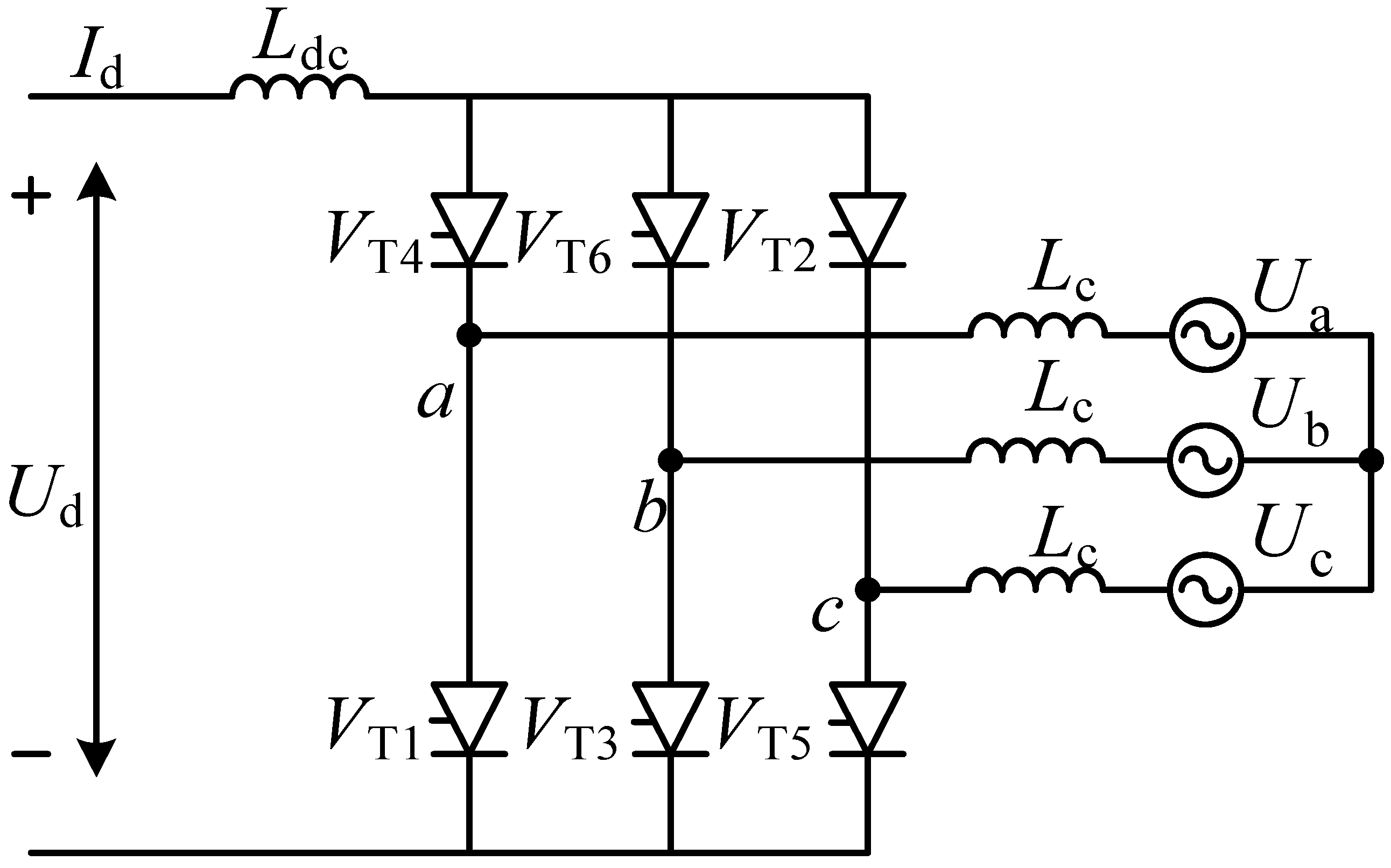
A single-bridge inverter is shown in Figure 1 [1]. Under the power frequency condition of 50 Hz, there is one thyristor on the upper and lower bridge arms during normal operation. When the inverter starts commutation, one of the thyristors of the upper arm or lower arm of the inverter that has been turned on will be turned off, the thyristors in the shutdown state will be turned on in order, and the process of alternate conduction of the thyristors in the upper and lower bridge arms is the commutation process [2].
During normal operation, the six valve arms of the six-pulse inverter will be turned on by the trigger pulse in order, and this article will start the analysis with the situation of the on state, where it can be seen that the next cycle will be converted to the state of simultaneous conduction. Before the valve is opened, only two valves are turned on, and now when the valve is triggered, they are all turned on at the same time. The equivalent circuit is shown in Figure 2b [3].
The equivalent circuit is shown in Figure 2b, In order to quantitatively analyze the LCC commutation process, assume that the current flowing through V T 3 in the commutation process is i 3 and the current flowing through V T 5 is i 5 , and at the same time, the direction of the current flow from the thyristor anode to the cathode is positive. The Kirchhoff voltage equation for phase B and phase C of the commutation branch in parallel is shown in Equation (1):
L c d i 5 d t + U b = L c d i 3 d t + U c
DC current satisfies Equation (2) in the commutation process:
i 3 + i 5 = I d
Because of commutation reactance, it is considered that the DC current remains constant during commutation, and Equation (1) is integrated:
π - β π - γ L c ( d i 5 d t d i 3 d t ) d ( ω t ) = π - β π - γ ( U c U b ) d ( ω t )
giving the solution:
2 X c I d = 2 U L ( cos γ cos β )
Further simplification of Equation (4) yields the mathematical expression of the off angle as follows [30]:
γ = arccos ( 2 X c I d 2 U L + cos β )
It can be seen from Equation (5) that the size of the arc extinguishing angle is closely related to the AC voltage, DC current, leading trigger angle, and equivalent commutation reactance. In the case of the constant, only the ratio will affect the on state. The essence of commutation failure is that it is less than its intrinsic limit value, i.e., the ratio is too large to cause the value to be too small. Therefore, excessive current and AC voltage drop are the most important reasons for continuous commutation failure.

3. Analysis of LCC-HVDC Commutation Failure Mechanism

3.1. LCC-HVDC Control Structure Composition

Taking a typical LCC-HVDC system as an example, the rectifier side and inverter side control structures are shown in Figure 3 [28].
When an AC fault occurs on the inverter side of the system, due to the characteristics of linear adjustment, when the DC voltage drops to the setting value, VDCOL begins to be put into operation, and the output value of the DC current command is reduced, which accelerates the commutation process of the system, can reduce the probability of commutation failure of the system, reduce the reactive power consumption of the inverter station, and is conducive to the recovery of the converter bus voltage and accelerates the recovery speed of DC active power. The equation for the corresponding VDCOL characteristic curve is expressed as follows in Equation (6) [22]:
I ord = { I dl I dh I dl U dh U dl U I dh + U dh I dl U dl I dh U dh U dl , , , U U dl U dl < U U dh U dh < U
In Equation (7), U dl and U dh are the upper and lower limits of DC voltage, I dl and I dh are the upper and lower limits of the current command value, U is the starting voltage of the VDCOL control link, and I ord is the output current command value of the conventional VDCOL.

3.2. LCC-HVDC Continuous Commutation Failure Mechanism

Figure 4 shows a simulation experiment of continuous commutation failure based on the PSCAD/EMTDC standard CIGRE test model. A single-phase ground fault occurs in the standard test model at 1 s for a duration of 0.3 s. From Figure 4, the process of continuous commutation failure can be divided into four stages.
Stage 1: A single-phase ground fault occurs on the inverter side, resulting in a large increase in the DC current on the inverter side, a rapid decrease in the VDCOL output current command value, a rapid reduction in the shutdown angle, and the first commutation failure of the inverter. The command value of the DC current on the rectifier side is less than the actual DC current value on the inverter side.
Stage 2: The DC current command value on the rectifier side is greater than the actual DC current value on the inverter side, the current deviation control is started, and the inverter station maintains control of the fixed shutdown and break angle. Improper interaction between the inverter side controllers in stages 3 and 4 is the key reason for the subsequent commutation failure [28].
Stage 3: The trigger angle command on the inverter side is changed from constant turn-off angle control to constant current control. In phase 3, the current deviation control is always active.
Stage 4: The inverter side is converted to the fixed shutdown angle control, because the DC current command value on the rectifier side is smaller than the actual DC current value on the inverter side, so the current deviation control is turned off, the output of the shutdown angle γ CEC compensation is 0, and the shutdown angle margin is reduced. At this time, the system has not resumed normal operation, and continuous commutation failure occurs on the inverter side.
In summary, due to the low sensitivity of the conventional VDCOL DC current regulation command in the LCC-HVDC system, the system will fail to continuously communicate to different degrees, that is, the sudden drop and rapid rise in the VDCOL output current command will increase the risk of continuous commutation failure in the LCC-HVDC system. From the analysis in the first section, the large increase in DC current and the sharp drop in AC voltage during the fault period will also lead to a decrease in the shutdown angle, thereby increasing the probability of continuous commutation failure. To solve the above problems, this paper proposes a suppression strategy for continuous commutation failure by combining turn-off angle compensation and dynamic nonlinear VDCOL.

4. Joint Control Strategy to Suppress Continuous Commutation Failure of LCC-HVDC System

4.1. Dynamic Nonlinear VDCOL Control Strategy

According to the analysis of the continuous commutation failure of the LCC-HVDC system in the previous chapter, when the system has a serious AC failure, the conventional VDCOL system is very prone to continuous commutation failure due to the insufficient sensitivity of DC command adjustment. Therefore, it needs to be optimized on a regular basis. Based on the above theoretical analysis, a continuous commutation failure suppression strategy based on nonlinear VDCOL was designed. According to the analysis in Section 2, to reasonably design a dynamic nonlinear VDCOL control link, the following two requirements should be met [22].
(1) When the DC voltage or AC voltage on the inverter side is low, the reactive power supplied by the system is very small during this time, so the current should be increased slowly to reduce the reactive power loss of the converter station and promote the bus voltage to return to the normal level.
(2) After VDCOL adjustment, the voltage reaches a very high value. At this time, the system can produce greater reactive power and the current should be increased more rapidly, which is conducive to the reestablishment of the transmission capacity of the DC power grid and can also promote the recovery of the transmission power of the DC system so that the system can resume normal operation as soon as possible.
Firstly, considering the situation where the commutation voltage will drop before and after the commutation failure, to dynamically adjust the sum of the upper and lower limits of the control voltage U dl and U dh according to the fault severity of the AC system, the fault coefficient k [27] and the commutation voltage change coefficient k U are introduced, as shown in Equation (7):
k = 1 U ac U acn , 0 g 1 , U ac U acn = k U
where: U ac indicates the effective value of the phase voltage of the AC system on the inverter side, and U acn represents the rated value of the phase voltage. The sum of the upper and lower limits of the new voltage U dlc and U dhc is shown in Equation (8):
{ U dlc = U dl + 0.1 k U dhc = U dh + 0.1 k
When a fault occurs, considering the two principles of (1) and (2), after theoretical analysis, the function y = a ( U + G k U ) n + b (a and b are non-zero constants) is selected and the basic curve is optimized. Given k U suitable gain G in this function, the dynamic nonlinear VDCOL control operation characteristics are shown in Equation (9):
I ord = { I dl a ( U + G k U ) 4 I dh + b , , , U U dlc U dlc < U U dhc U dhc < U
The dynamic nonlinear VDCOL design is shown in Figure 5.
The DC current command for normal operation of the system in conventional VDCOL is 1.0 p.u. I dl = 0.55   p . u . , I dh = 1   p . u . , U dl = 0.4   p . u . , U dh = 0.9   p . u . . When the actual operating voltage U d < 0.9   p . u . , VDCOL adjusts the DC current command in real time according to the DC voltage, and when U d < 0.4   p . u . , the DC current command is maintained at 0.55 p.u. The control strategy regulates the instruction value of DC current to a certain extent, but the mathematical model adopted is fixed, resulting in the fixed starting voltage value of each current instruction section, and the linear relationship between voltage and current in the recovery trend of conventional VDCOL leads to a fixed slope, so the adjustment sensitivity of the current command is not high and the variable voltage before and after the commutation failure is not considered. The dynamic nonlinear VDCOL control method proposed in this paper can dynamically adjust the upper and lower limits of the DC voltage according to Equations (7) and (8) with the amplitude of the AC voltage drop, as can be seen from Figure 5. When U d < U dlc , the DC current instruction was taken as 0.55 p.u. When U dlc < U d < U dlh , at the initial stage of the fault, the improved VDCOL under the same DC voltage can obtain a smaller DC current command value, which can speed up the adjustment speed of the DC current instruction and realize the rapid suppression of DC current and the effective suppression of continuous commutation fault. At the same time, when the DC voltage reaches a higher level, the current can reach a higher DC current command value and increase at a faster rate. It can quickly reduce the reactive power consumption of the DC system and improve the voltage recovery ability of the system. On this basis, the commutation voltage change coefficient is increased to further suppress the drop in VDCOL input voltage, improve the sensitivity of dynamic nonlinear VDCOL, and further improve the flexibility of the system. At the same time, due to the increase in dynamic nonlinear VDCOL input voltage, the decrease in the turn-off angle is suppressed to a certain extent based on the increase of DC current to better suppress the continuous commutation failure caused by system failure.

4.2. Shutdown Angle Compensation Control Strategy Based on Virtual Inductance

When a converter fails due to an AC system failure, the DC current increases, resulting in a decrease in the turn-off angle, and when the turn-off angle falls below the limit turn-off angle, the DC system experiences a commutation fault. Therefore, drawing on the role of the inductor in the circuit to limit the current, according to its physical expression, the first-order differential link is used to simulate and a virtual inductor is introduced to induce the change of current on the DC side, and this change is reflected in the control link of the fixed off and broken angle. In this way, when the AC system fails, the virtual inductor can quickly sense the change of DC current and convert the current change into a turn-off angle compensation amount, which acts on the fixed-off angle control, and the combination of the two can jointly achieve the purpose of reducing the DC side current during the fault.
The concept of virtual inductance is introduced into the DC transmission control system, which is used as the carrier of the current change rate on the DC side in real time to reflect the dynamic change process of DC current, and its mechanism is described as follows.
In the case of a fault-free AC system, that is, during normal operation, the DC side current is constant, and its rate of change is 0, so the amount of off-angle compensation carried on the virtual inductor is also 0, as shown in Equation (10):
Δ γ * = L * d I di d t = 0
where L * is the set virtual inductance value. It can be seen from Equation (10) that when the system is running at a steady state, the voltage drop of the virtual inductor is 0, which does not affect the control of the fixed off angle, so the operating parameters of the system will not be affected.
When the AC system fails, the DC side current changes, acts on the virtual inductor, induces the DC current change rate in real time, converts it into a turn-off angle compensation amount, and acts on the fixed turn-off angle control, as shown in Equation (11):
Δ γ * = L * d I di d t
The off-angle compensation control is shown in Figure 6.
During the period from the failure of the system to the return to normal, the DC side current will drop from the maximum value under the fault condition to the normal value, and the DC current change rate will be negative, so Equation (11) is corrected:
Δ γ * = L * | d I di d t |
Δ γ * is calculated from Equation (12), from the beginning of the fault to the full recovery of the AC voltage period: Δ γ * 0 is constant which is conducive to the stable recovery of the commutation process.
In summary, this paper proposes a joint strategy for continuous commutation failure suppression by fusing turn-off angle compensation and dynamic nonlinear VDCOL, as shown in Figure 7.

5. Simulation Results and Discussion

To verify the effectiveness of the proposed control method in suppressing the continuous commutation failure of the LCC-HVDC system and to determine the relevant parameters in the proposed method, a simulation model (Figure 8) was built and verified in PSCAD/EMTDC based on the CIGRE-HVDC standard test model. The main parameters of the system are shown in Table A2 and Table A3.

5.1. Determination of Virtual Inductance Parameters

In the simulation experiment, because of the large current change at the beginning of the system, the virtual inductance is set to avoid playing a role in this process and only make it work after the system is stable and normal. When the value L * is small, the impact on the DC current on the inverter side is small, resulting in a weak response to the DC terminal current, which affects the recovery effect of the system after the fault. However, if the selected value is too large, it will be too sensitive to the current fluctuation on the DC side, so the system will oscillate in the event of a fault and the stable operation of the system cannot be guaranteed. Therefore, the selection of an appropriate value is crucial for the effectiveness of the proposed control strategy [29].
Since the specific value L * cannot be accurately obtained theoretically, a series of simulation experiments will be carried out to obtain the fault recovery characteristic data of the system to determine the optimal value L * for the shutdown angle compensation control strategy based on virtual inductance (Table 1). The specific scheme is to build the model shown in Figure 8 in PSCAD/EMTDC and set a single-phase grounding fault at the AC bus on the inverter side (the fault occurrence time is 1 s, the transition inductance is 0.63 H, and the duration is 0.5 s).
Compare the number of commutation failures and the system failure recovery time of the DC system at different times L * . This determines an optimal value.
Through the analysis of the simulation results in Table 2, it can be found that setting the parameter value of the virtual inductor too large or too small will weaken the system’s ability to suppress continuous commutation failures and increase the recovery time of the system to varying degrees, which is also consistent with the previous analysis. Comparing the data in the table, it is more reasonable to take 0.006 as the value L * .

5.2. Gain Coefficient G Is Determined

Because this value cannot be accurately derived theoretically, a series of simulation experiments are set up in this paper, and the control variable method is used to simulate and analyze it to determine the optimal value of the gain G of the commutation voltage change coefficient. By setting a single-phase grounding fault (the occurrence time is 1 s, the transition inductance is 0.6 H, and the duration is 0.5 s) at the AC bus on the inverter side, the number of commutation failures and the system fault recovery time of the DC system at different G values in Table 3 are compared to determine an optimal value.
Through the analysis of the simulation results in Table 3, it can be found that setting the gain parameter G of the commutation voltage change coefficient too large or too small will weaken the ability of the system to suppress continuous commutation failure and will increase the recovery time of the system to varying degrees, which is also consistent with the previous analysis. Comparing the data in the table, it is more reasonable to take 0.2 as the G value.

5.3. Simulation Analysis and Verification

The operating characteristics of conventional VDCOL and dynamic nonlinear VDCOL during normal operation are shown in Figure 9.
As can be seen from Figure 9, when a slight short-circuit fault occurs on the inverter side of the system, no commutation fault will occur on the three control strategies. The results showed that the inhibition strategy proposed in this paper did not cause adverse reactions. In addition, in the case of control strategy 2 and control strategy 3, the DC current fluctuation amplitude of the system is smaller and the DC power drop is lower, that is, the response to the fault is more sensitive.
The following three methods are contrasted and analyzed to confirm the superiority of the continuous commutation failure suppression strategy presented in this paper.
Control strategy 1: Control strategy using the CIGRE standard test model.
Control strategy 2: Because of 1, the ordinary low-voltage current-restricting control is supplanted by the proposed dynamic nonlinear VDCOL control.
Control strategy 3: Because of 2, a shut-off angle compensation control strategy based on virtual inductance is added.
The inductor grounding is set at the converter bus on the inverter side to simulate single-phase or three-phase short-circuit faults in LCC-HVDC systems in practice. The smaller the value, the closer the short-circuit location is to the converter bus and the greater the degree of fault.
In case 1, a single-phase grounding fault is set at the AC bus on the inverter side, the grounding inductance is L f = 1 H , the fault duration is 0.5 s, and the dynamic characteristics of the system under different schemes are shown in Figure 10.
As can be seen from Figure 10, in the case of the original control strategy, because the fault occurs far away and is relatively slight, the DC current did not rise significantly, only rising to 1.23 p.u. The DC power only fell to 0.6 p.u. The inverter side of the LCC-HVDC system will not have a commutation failure, and the system will return to normal operation after the fault is eliminated. In the case of control strategy 2, there will be no commutation failure on the inverter side of the LCC-HVDC system. However, in the case of control strategy 2, the amplitude of the system’s DC current fluctuation is smaller, and the DC power drop is lower, i.e., the response to faults is more sensitive. When control strategy 3 is used instead, the DC current command value of the system decreases more, and the shutdown angle increases more. After a large number of simulation analyses, it can be seen that for the lighter AC system fault, the inverter side of the LCC-HVDC system will not fail to commutate by using control strategy 1, control strategy 2 and control strategy 3, and the fault recovery ability of the three control strategies is similar, but the performance of control strategy 2 and control strategy 3 in terms of commutation failure immunity is better.
In case 2, set a single-phase grounding fault at the AC bus on the inverter side, with ground inductance L f = 0.6 H and duration of failure 0.5 s. The dynamic characteristics of the system under different control strategies are shown in Figure 11.
It can be seen from Figure 11 that when using control strategy 1, because the fault is more serious, the system has the first commutation failure and then a continuous commutation failure. The shut-off angle on the inverter side drops to 0 three consecutive times, and in the process of the first two commutation failures, the DC current is increased to 2 p.u., the voltage fluctuation amplitude on the DC side is also greater, and the system does not resume normal operation until the fault is removed. When control strategy 2 and control strategy 3 are adopted, it can be seen from Figure 11 that the first commutation failure of the system is still unavoidable, but there is no subsequent commutation failure on the inverter side of the LCC-HVDC system after that. The DC current can be constrained more quickly according to the change in DC voltage, which has better stability in the fault recovery phase of DC current and DC voltage and can also greatly reduce the fault recovery time. The DC current fault recovery time of control strategy 2 is 0.3 s shorter than that of control strategy 1, and the current fault recovery time of control strategy 3 is 0.34 s shorter than that of control strategy 1. This method enables the system to quickly return to a steady state after the first commutation failure, which improves the reliability of the system. In addition, control strategy 3 has a smaller increase in DC current and a greater increase in the shutdown angle when the system fails for the first commutation failure, resulting in increased commutation failure immunity.
In case 3, set a three-phase grounding fault at the AC bus on the inverter side, with ground inductance L f = 0.6 H and duration of failure 0.5 s. The dynamic characteristics of the system under different control strategies are shown in Figure 12.
As can be seen from Figure 12, the system has a continuous commutation failure when control strategy 1 is used, during which the shutdown angle on the inverter side drops to 0 two consecutive times and the DC current rises to 2 p.u. when the first and second commutation failures occur. The voltage fluctuation on the DC side is relatively large, and the LCC-HVDC system does not start working again until the fault is eliminated. When control strategy 2 and control strategy 3 are adopted, it can be seen from Figure 12 that the three control strategies still cannot avoid the first commutation failure of the system, but there is no subsequent commutation failure on the inverter side of the LCC-HVDC system thereafter. The DC current fault recovery time of control strategy 2 is shortened by 0.24 s compared with control strategy 1, and the current fault recovery time of control strategy 3 is shortened by 0.19 s compared with control strategy 1. The DC current stability and recovery speed of the two control strategies are better than those of control strategy 1, and the recovery speed and stability of the system are better than those of control strategy 2 under the condition of a three-phase severe fault.
To test the inhibition effect of the optimal solution on commutation failure at different fault levels, the fault severity is simulated by changing the ground inductance value in the CIGRE benchmark model. The fault level proposed in reference [28] is used for comparison, and the calculation formula is shown in Equation (13):
f L = U L ω L f P d × 100 %
In Equation (13), U L is the effective voltage value of the AC bus on the inverter side, L f is the value of the grounding inductance, P d is the rated power of the DC transmission system, f L represents the severity of the ground fault that will occur in the LCC-HVDC system when the system has an AC fault, and the higher the f L , the more serious the AC fault in the system.
At the AC bus on the inverter side, the inductor grounding fault is set, the fault time is 1 s, the fault duration is 0.5 s. This is simulated, and analyzed in detail. The total number of system commutation failures in control strategy 1, control strategy 2 and control strategy 3 under various fault severity are analyzed in detail, and the specific situation is shown in Table 3.
It can be seen from Table 3 that when the fault level is low, that is, when the fault level ranges from 5% to 15%, none of the three control strategies will have continuous commutation failure in the case of a single-phase grounding fault. When the fault level ranges from 5% to 10%, none of the three control strategies will have continuous commutation failure in the case of a three-phase fault. When the fault level is between 20% and 50%, in the case of a single-phase grounding fault, the control protection strategy proposed in this paper can achieve a larger protection range and better protection effect in restraining continuous commutation failure. According to the statistical results of three-phase grounding faults, both methods can effectively prevent continuous commutation failure under mild faults. Moreover, the suppression effect of control strategy 3 under the three-phase serious ground fault is better than that of control strategy 2. In summary, the control strategy proposed in this paper can effectively reduce the probability of continuous commutation failure in the fault recovery stage of the LCC-HVDC system and can effectively suppress it.

6. Conclusions

Based on the problem of continuous commutation failure when an AC fault occurs on the inverter side of an LCC-HVDC system, this paper studies the mechanism of continuous commutation failure from multiple perspectives and designs a new multi-objective cooperative control method based on this to effectively suppress continuous commutation failure. The control strategy considers the low sensitivity of the DC current command of the conventional VDCOL in the LCC-HVDC system and the problem that the rapid rise of DC current and the decrease of commutation voltage during the fault will lead to the decrease of the shutdown angle. Through theoretical and simulation analysis, the following conclusions can be obtained.
(1) Because of the low sensitivity of current command regulation under the conventional VDCOL control mode, a dynamic nonlinear VDCOL control method is designed, in which a new mathematical model is proposed to change the operation characteristics of the conventional VDCOL voltage and current fixation. Firstly, the voltage before and after the commutation failure is dynamically adjusted by the degree of AC voltage drop, and considering the variable voltage before and after the commutation failure, the failure coefficient is introduced to modify the voltage. Secondly, the conventional VDCOL is designed as a nonlinear control structure and the DC current command is reasonably regulated. Compared to traditional VDCOL, dynamic nonlinear VDCOL control has better immunity to single-phase ground faults. The nonlinear dynamic VDCOL control proposed in this paper can effectively suppress the increase in DC current to improve the stability of the system. At the same time, the shutdown angle compensation mechanism based on virtual inductance is introduced to improve the commutation margin of the shutdown angle, which effectively solves the problem that VDCOL cannot suppress the commutation failure when a three-phase grounding fault occurs.
(2) The joint control method proposed in this paper is only for the VDCOL components in the control system, is more compatible with other optimal control strategies, and does not require additional auxiliary equipment, making it cheaper and easier to implement. In addition, a shut-off angle compensation control strategy based on virtual inductance is proposed, which is also a control method in the control link, not the real inductance, which reduces the hardware investment and site occupation. This is adaptable, economical, and practical.
(3) This method can more effectively reduce the possibility of continuous commutation failure of the LCC-HVDC system under various fault levels, shorten the recovery time of the LCC-HVDC system under faults, and make the system enter the stable operation mode faster, which has obvious advantages compared with the conventional control mode. The continuous commutation failure suppression strategy proposed in this study by fusing turn-off angle compensation and dynamic nonlinear VDCOL provides a new idea for preventing and suppressing commutation faults, significantly reduces the transmission loss caused by renewable energy access to the power grid, alleviates the energy sustainability problem to a certain extent, and has important theoretical guiding significance for the planning and operation of an HVDC system.
(4) The electrical quantity related to the system has certain fluctuations in the transient process of fault recovery, the low-pass filtering method is used to smooth out the influence of the above fluctuations on the shutdown angle compensation, and the filter parameter design needs to be further studied in the future. The commutation failure can be suppressed by control measures such as early triggering and adjusting the DC current command value, but the suppression measures are independent of one another and their response times are different. Future research should examine the coordinated control and coordination strategies of different commutation failures and clarify the interaction between different control measures.

Author Contributions

H.L.: conceptualization, methodology, and original writing, formal analysis, and validation. G.J.: conceptualization, methodology, and supervision. All authors have read and agreed to the published version of the manuscript.

Funding

This research was funded by the National Key Research and Development Program of China, grant number 2021YFB2400900.

Institutional Review Board Statement

Not applicable.

Informed Consent Statement

Not applicable.

Data Availability Statement

The data can be provided upon the request of the authors.

Conflicts of Interest

The authors declare no conflicts of interest.

Appendix A

Table A1. Nomenclature and numerical values.
SymbolsParameter NameParameter Size
U d DC voltage
I d DC current
I dr DC current on the rectifier side
I di DC current on the inverter side
U dr DC voltage on the rectifier side
U di DC voltage on the inverter side
α r The triggering angle of the output is controlled by the rectifier siding current
I dr_ord DC current command value on the rectifier side
I res DC current reference angle
Δ I d Current margin
β i Trigger lead angle of variable side
γ CEC Turn-off angle compensation for current deviation control
R V Compensating resistance
γ i Turn-off angle measurement
β CC The triggering advance angle of the output is controlled by the inverter side setting the current
β CEC the triggering advance angle of the output is controlled by the fixed turn-off angle.
U dl , U dh Upper and lower limits of DC voltage
I dh , I dl Upper and lower limits of DC current
U The start-up voltage of the VDCOL control link
I ord Conventional VDCOL output current command value
k Failure factor
U ac The effective value of the phase voltage of the AC system on the inverter side
U acn Phase voltage rating187.79 kV
U dl _ c , U dl _ c New upper and lower limits for voltages
k U Commutation voltage change factor
γ min Minimum cutoff angle7.2°
L * Virtual inductors0.006
Δ γ * Turn-off angle compensation
L d Line inductance0.5968 H
R d Line resistance2.5 Ω
C Line capacitance26 μF
L f Ground inductance
f L Fault level
U L RMS voltage of the AC bus on the inverter side215.05 kV
P d Rated active power1000 MW
Table A2. AC system parameters of HVDC transmission.
Main Parameters of the AC System
AC System Voltage/kVRated Voltage/kVReactive Power Compensation Capacity/MvarFundamental Impedance/ΩSCR
Rectifier side382.934562647.7∠84°2.5
Inverter side215.123062621.2∠75°2.5
Converter Transformer Parameters
Ratio/kVcapacity/MVAShort-Circuit Impedance/p.u.
Rectifier side345/2135910.18
Inverter side230/2096030.18
Table A3. HVDC transmission DC line parameters.
Main Parameters of the DC Line
Rated voltage/kv500Inductance/H0.6
Rated power/MW1000Resistance/Ω 2626
Rated current/kA2Capacitance/μF2.5

References

  1. Wang, Y.; Wang, H.; Wu, J. Analysis of Asymmetric Fault Commutation Failure in HVDC System Considering Instantaneous Variation of DC Current. Sustainability 2023, 15, 11796. [Google Scholar] [CrossRef]
  2. Mitali, J.; Dhinakaran, S.; Mohamad, A.A. Energy storage systems: A review. Energy Storage Sav. 2022, 1, 166–216. [Google Scholar] [CrossRef]
  3. Zhu, L.Z.; Niu, C.; Wang, Z.B. An Extinction Angle Dynamic Compensation Control Method for Suppressing Continuous Commutation Failure. Proc. CSEE 2021, 41, 7621–7630. [Google Scholar]
  4. Zhou, H.; Yao, W.; Ai, X.; Li, D.; Wen, J.; Li, C. Comprehensive Review of Commutation Failure in HVDC Transmission Systems. Electr. Power Syst. Res. 2022, 205, 107768. [Google Scholar] [CrossRef]
  5. Li, P.P.; Zhou, H.Y.; Yao, W.; Wang, L.R.; Yang, C.X.; Li, C.H.; Wen, J.Y. Review of Commutation Failure on HVDC Transmission System Under Background of Multi-infeed Structure. Power Syst. Technol. 2022, 46, 834–850. [Google Scholar]
  6. Xue, Y.; Zhang, X.-P.; Yang, C. Elimination of Commutation Failures of LCC HVDC System with Controllable Capacitors. IEEE Trans. Power Syst. 2015, 31, 3289–3299. [Google Scholar] [CrossRef]
  7. Song, J.; Li, Y.; Zeng, L.; Zhang, Y.; Yang, Z. Mechanism Analysis and Prevention Methods of Commutation Failure in LCC-HVDC Transmission System. In Proceedings of the 2019 IEEE 8th International Conference on Advanced Power System Automation and Protection (APAP), Xi’an, China, 21–24 October 2019; pp. 556–560. [Google Scholar]
  8. Ou, K.J.; Ren, Z.; Jing, Y. Research on commutation failure in HVDC transmission system Part1: Commutation failure factors analysis. Electr. Power Autom. Equip. 2003, 23, 5–8. [Google Scholar]
  9. Ren, Z.; Ou, K.J.; Jing, Y. Research on commutation failure in HVDC transmission system part 2: Measures against commutation failure. Electr. Power Autom. Equip. 2003, 23, 6–9. [Google Scholar]
  10. Chen, S.Y.; Li, X.N.; Yu, J.; Li, T.; Lu, P.; Yin, Y. A method based on the detection of the sin-cos components mitigates commutation failure in HVDC. Pros. Chin. Soc. Electr. Eng. 2005, 25, 6. [Google Scholar]
  11. Li, X.; Zhang, C.Z.Y.; Cai, W.Y.; Tan, Z.P.; Chen, Z.S.; Cai, Z.X. Improvement of HVDC CFPREV based on a three-phase simultaneity sampling values algorithm. Power Syst. Prot. Control 2020, 48, 170–176. [Google Scholar]
  12. Tamai, S.; Naitoh, H.; Ishiguro, F.; Sato, M.; Yamaji, K.; Honjo, N. Fast and predictive HVDC extinction angle control. IEEE Trans. Power Syst. 1997, 12, 1268–1275. [Google Scholar] [CrossRef]
  13. Xiao, H.; Li, Y.; Lan, T. Sending End AC Faults Can Cause Commutation Failure in LCC-HVDC Inverters. IEEE Trans. Power Deliv. 2020, 35, 2554–2557. [Google Scholar] [CrossRef]
  14. Ma, X.; Li, F.; Yin, C. Impact of voltage restoration of commutation bus on rectifier side on commutation of inverters. Power Syst. Technol. 2020, 44, 2950–2956. [Google Scholar]
  15. Guo, C.; Liu, Y.; Zhao, C.; Wei, X.; Xu, W. Power Component Fault Detection Method and Improved Current Order Limiter Control for Commutation Failure Mitigation in HVDC. IEEE Trans. Power Deliv. 2015, 30, 1585–1593. [Google Scholar] [CrossRef]
  16. Wei, Z.; Yuan, Y.; Lei, X.; Wang, H.; Sun, G.; Sun, Y. Direct-current predictive control strategy for inhibiting commutation failure in HVDC converter. IEEE Trans. Power Syst. 2014, 29, 2409–2417. [Google Scholar] [CrossRef]
  17. Gole, A.M.; Meisingset, M. Capacitor commutated converters for long-cable HVDC transmission. Power Eng. J. 2002, 16, 129–134. [Google Scholar] [CrossRef]
  18. Guo, C.; Zhang, Y.; Gole, A.M.; Zhao, C. Analysis of dual-infeed HVDC with LCC-HVDC and VSC-HVDC. IEEE Trans. Power Deliv. 2012, 27, 1529–1537. [Google Scholar] [CrossRef]
  19. Hou, L.; Zhang, S.; Wei, Y.; Zhao, B.; Jiang, Q. A dynamic series voltage compensator for the mitigation of LCC-HVDC commutation failure. IEEE Trans. Power Deliv. 2021, 36, 3977–3987. [Google Scholar] [CrossRef]
  20. He, D.; Wen, J.; Geng, X.; Wang, S.; Zhang, L.; Cai, Y.; Luo, Z.; Tan, M. Study on HVDC commutation failure and voltage compensated variable slope VDCOL control. In Proceedings of the 2018 2nd IEEE Conference on Energy Internet and Energy System Integration (EI2), Beijing, China, 20–22 October 2018; pp. 1–6. [Google Scholar]
  21. Nguyen, M.H.; Saha, T.K.; Eghbal, M. Master self-tuning VDCOL function for hybrid multi-terminal HVDC connecting renewable resources to a large power system. IET Gener. Transm. Distrib. 2017, 11, 3341–3349. [Google Scholar] [CrossRef]
  22. Li, Y.-J.; Wang, J.-J.; Li, Z.-L.; Fu, C. VDCOL parameters setting influenced by reactive power characteristics of HVDC system. In Proceedings of the 2016 International Conference on Smart Grid and Clean Energy Technologies (ICSGCE), Chengdu, China, 19–22 October 2016; pp. 364–370. [Google Scholar]
  23. Zhang, B.; Wang, Y.; Li, X. Overview on VDCOL control strategy for improving DC system recovery characteristics. East China Electr. Power Syst. 2016, 42, 826–832. [Google Scholar]
  24. Liu, L.; Wang, Y.; Li, X. Design of variable slope VDCOL controller based on fuzzy control. Power Syst. Technol. 2015, 39, 1814–1818. [Google Scholar]
  25. Hong, J.; Qin, L. The Influence of VDCOL Parameters on the Recovery Characteristic after Commutation Failures of HVDC Links Fed into Weak AC Systems. In Proceedings of the 2022 4th International Conference on Power and Energy Technology (ICPET), Beijing, China, 29–31 July 2022; pp. 432–437. [Google Scholar]
  26. Liu, X.Y.; Wang, Z.P.; Zheng, B.W.; Wang, T.; Qiao, X. Mechanism analysis and mitigation measures for continuous commutation failure during the restoration of LCC-HVDC. Proc. CSEE 2020, 40, 3163–3172. [Google Scholar]
  27. Meng, Q.Q.; Liu, Z.H.; Hong, L.R.; Zhou, X.; Xia, H.T.; Liu, Y.F.; Wang, X. A suppression method based on nonlinear VDCOL to mitigate the continuous commutation failure. Power Syst. Prot. Control 2019, 47, 119–127. [Google Scholar]
  28. Liu, L.; Lin, S.; Liu, J.; Sun, P.; Li, X.; He, Z. Mechanism analysis of continuous commutation failure caused by improper interaction of controllers. Power Syst. Technol. 2019, 43, 3562–3568. [Google Scholar]
  29. Lu, Y.; Tong, K.; Ning, L.R.; Xuan, J.; Guo, C.; Zhao, C. A Method Mitigating Continuous Commutation Failure for Double-Infeed HVDC System Based on Virtual Inductor. Power Syst. Technol. 2017, 41, 1503–1509. [Google Scholar]
  30. Guo, C.Y.; Li, C.H.; Liu, Y.C.; Jiang, B.; Zhao, C.; Zhou, Q. A DC Current Limitation Control Method Based on Virtual Resistance to Mitigate the Continuous Commutation Failure for Conventional HVDC. Proc. CSEE 2016, 36, 4930–4937+5117. [Google Scholar]
Figure 1. Equivalent circuit diagram of single bridge inverter.
Sustainability 16 02145 g001
Figure 2. (a) Topology diagram of commutation process; (b) Commutation process equivalent circuit diagram. When analyzing a circuit containing a valve, it can be considered a special linear circuit. Before the commutation begins, it is in the conduction state. After a while, the LCC-HVDC system applies a trigger pulse to the valve in a certain order. Because the voltage added to the valve is positive, it is opened immediately once triggered, and the valve is commutated under the action of commutation voltage and current. In this process, the current of the valve gradually increases, and the current flowing through the valve gradually decreases. The commutation overlap angle is the electrical angle that corresponds to this period. When the process of commutation is finished, the converter valve must be under the action of the reverse voltage for a long enough time, and the corresponding electrical angle during this time is called the shut-off angle. The corresponding electrical angle is about 7°. When the inverter is in operation, the thyristor closing angle must be greater than this value; otherwise, the valve will turn on again without triggering due to the incomplete recovery of the blocking ability, and the system will have its first commutation failure [5].
Sustainability 16 02145 g002
Figure 3. CIGRE HVDC system control block diagram.
Sustainability 16 02145 g003
Figure 4. Waveform diagram of continuous commutation failure mechanism.
Sustainability 16 02145 g004
Figure 5. Dynamic nonlinear VDCOL curve variation diagram.
Sustainability 16 02145 g005
Figure 6. Control block diagram of turn-off angle compensation.
Sustainability 16 02145 g006
Figure 7. Block diagram of joint control strategy.
Sustainability 16 02145 g007
Figure 8. LCC-HVDC system structure.
Sustainability 16 02145 g008
Figure 9. Operating characteristics of the system under normal working conditions: (a) DC voltage; (b) DC current; (c) Turn-off angle; (d) Active power; (e) DC current instruction.
Sustainability 16 02145 g009
Figure 10. System operating characteristic diagram under single-phase ground fault ( L f = 1 H ): (a) DC voltage; (b) DC current; (c) Turn-off angle; (d) Active power; (e) DC current instruction.
Sustainability 16 02145 g010
Figure 11. System operating characteristics diagram under single-phase ground fault ( L f = 0.6 H ): (a) DC voltage; (b) DC current; (c) Turn-off angle; (d) Active power; (e) DC current instruction.
Sustainability 16 02145 g011
Figure 12. System operating characteristics under three-phase ground fault ( L f = 0.6 H ): (a) DC voltage; (b) DC current; (c) Turn-off Angle; (d) Active power; (e) DC current instruction.
Sustainability 16 02145 g012
Table 1. System failure characteristics are based on different virtual inductance value.
Coefficient L*/p.u.Number of Commutation FailuresFailure Recovery Time/s
0.00220.581
0.00420.582
0.00610.571
0.00810.583
0.00910.573
0.0110.584
Table 2. System fault characteristics with different values of G.
Coefficient G ValueNumber of Commutation FailuresFailure Recovery Time/s
0.0530.735
0.0620.586
0.0820.584
0.120.596
0.1220.609
0.1410.608
0.1620.620
0.1820.633
0.210.582
0.2210.614
Table 3. Total number of system commutation failures under different fault levels.
Fault Level/%Single-Phase FaultThree-Phase Fault
Control Strategy 1Control Strategy 2Control Strategy 3Control Strategy 1Control Strategy 2Control Strategy 3
5000000
10000000
15000211
20311211
25321211
30321211
35421211
40211221
45321231
50321331
Disclaimer/Publisher’s Note: The statements, opinions and data contained in all publications are solely those of the individual author(s) and contributor(s) and not of MDPI and/or the editor(s). MDPI and/or the editor(s) disclaim responsibility for any injury to people or property resulting from any ideas, methods, instructions or products referred to in the content.

