Abstract
Solar energy has become an energy source for a wide range of uses, including in solar cookers, due to its availability, cleanliness, environmental friendliness, and sustainability. In this study, an indirect solar cooker was investigated by measuring its thermal performance using a Graphene Oxide (GO) nanofluid. Water, GO (250 ppm)-water, and GO (500 ppm)-water were used as heat transfer fluids. The experimental set-up consisted of the cooking part and a solar collector, which are the two essential elements in indirect solar cookers. The cooking part was a wooden box solar cooker, and the parabolic trough solar collector was a polished stainless steel structure. The solar cooker was assessed using the stagnation test and load test as well as energy and exergy measurements. According to the test results, the averaged F1 was 0.1 for the base fluid water, 0.11 for GO (250 ppm)-water, and 0.13 for GO (500 ppm)-water. In addition, using a GO nanofluid instead of water in the solar cooker, the system’s thermal performance, energy, and exergy efficiency were improved. The use of the GO (250 ppm)-water and GO (500 ppm)-water nanofluids instead of water in the system improved the overall energy efficiency of the system by 3.3 and 4.2%. Moreover, using GO (500 ppm)-water allowed for achieving superior performance.
1. Introduction
Solar thermal energy is one of the most sustainable and clean thermal energy resources and has attracted a lot of interest over the past few decades because of rising concerns about energy usage and experimental pollution [1]. In many households, cooking is a core daily activity as well as a basic human need. LPG, electricity, kerosene, fuel, etc. are among the most frequently utilized cooking fuels across the globe. Solar energy is gaining popularity, and people from all over the world are adopting solar-powered appliances like lights, water heaters, and cookers. Solar cookers offer several ecological and financial benefits in addition to cooking, such as the capacity to conserve energy other traditional cooking methods and lessen environmental pollution. In 1767, solar cooking became popular throughout the world [2]. From 1767 until now, multiple solar cooker designs have been successfully produced by several researchers and pioneers in the field, and some excellent designs are still in use. Solar cookers provide free and healthy cooking, which appeals to both modern city dwellers and rural residents in energy-strapped developing nations. A solar cooker is a gadget that uses the sun’s heat to heat and prepare food. Because they do not require fuel and are free to use, the great majority of solar cookers in use today are quite inexpensive to run. Today, several charitable organizations are encouraging their use on a global scale to minimize air pollution, fuel expenses (for low-income people), and the deforestation and desertification caused by harvesting firewood for cooking [3]. Generally, concentrating collectors—which direct the incoming sun radiation onto the receiver—are utilized to achieve good solar performance [4]. The parabolic trough collector (PTC) is one of the most extensively used solar energy converters among the currently available concentrated solar power technologies [4]. The thermal energy received from the sun is absorbed by the PTC receiver, which then transfers it to the Heat Transfer Fluid (HTF) [4]. Many devices for collecting solar energy have been developed and researched in recent years. One of them are the parabolic solar collectors, which can be employed in a variety of applications due to their distinctive properties. These devices consist of various parts, the two primary ones being a parabolic receiver and a tubular absorber [5].
Many researchers have conducted studies on the use of solar collectors like indirect solar cookers [6,7,8,9,10]. To fulfill the demands of rural populations, [11] a solar cooker with a PTC was created. In this cooker, a vacuum glass tube receives a concentrated amount of sunlight, and inside it, an oil is heated in a sizable tube. The cooking pot containing the food to be prepared is heated by the hot oil rising through two small tubes attached to a bigger tube. To determine whether a thermally exposed solar parabolic trough cooker is effective, [12] a mathematical model was created. The polished stainless steel parabolic trough used to construct the solar cooker had a concentration ratio of 9.867.
Due to their superior heat transfer capabilities over traditional base fluids and their high thermal characteristics, nanofluids are important in the transfer of heat [13]. Additionally, because they enhance the heat transfer’s surface area, nanoparticles in heat transfer fluids speed up the process of heat transmission. In conventional heat transfer fluids, nanofluids are created by scattering and steadily suspending nanoparticles, whose size in typically in the range of 1 to 100 nm [14]. Researchers demonstrated that nanofluids have superior heat conductivity and stronger convective heat transfer capability than base fluids through their usage in solar cooker applications [7,15,16,17]. Many studies investigated the nanofluid-based PTC experimentally and numerically. The use of water/Al2O3 in a PTC was investigated experimentally by Subramani et al. [18], and an 8.5% improvement in thermal efficiency was discovered. Coccia et al. [19] employed nanofluids (Syltherm 800/Cu) in a PTC. Mwesigye et al. [20] discovered through a numerical study that when using the Syltherm 800/Al2O3 nanofluid, the performance increased by around 7.6%. Furthermore, using the same nanofluid, Bellos et al. [21] computed a 4.3% thermal efficiency gain. Six water-based nanofluids were studied by Farhana et al. [22] at varying weight concentrations: Fe2O3, SiO2, TiO2, ZnO, Al2O3, and Au. As mentioned above, there are few published studies on indirect solar cookers based on the GO nanofluid. So, this study evaluates an indirect solar cooker’s performance through the stagnation test and load test as well as energy and exergy measurements. The primary goal of this research was to use a water-based GO nanofluid to enhance the performance of the solar cooker that was manufactured. Furthermore, a comparison was made between the efficiency of the nanofluid-based indirect solar cooker and that of the system that used water as the heat transfer fluid.
2. Geometrical Parameter-Based Mathematical Model of the PTC
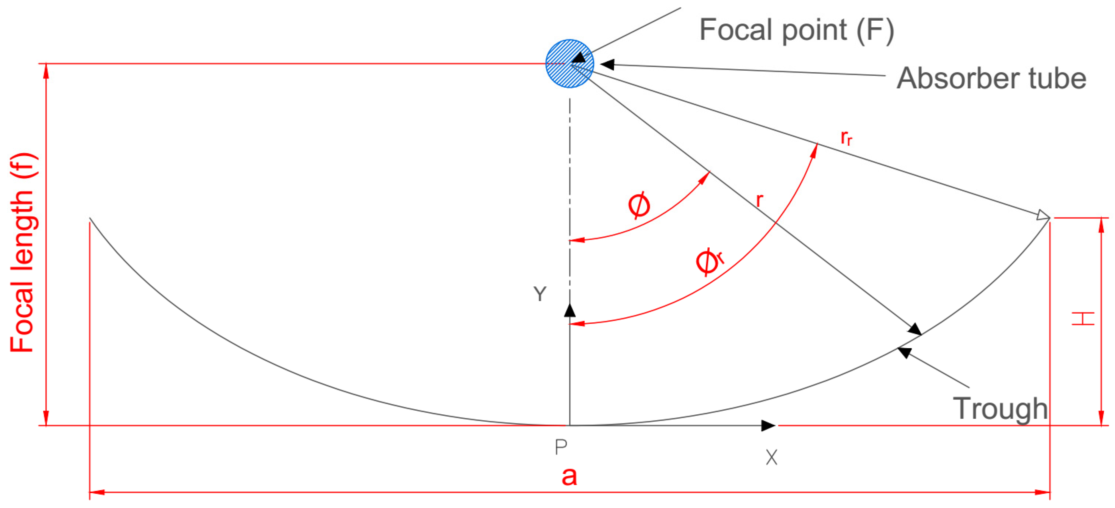
The fundamental idea at the base of how a PTC works is the optical ray diagram rule. Figure 1 depicts the crucial design parameters in a sectional, two-dimensional view.
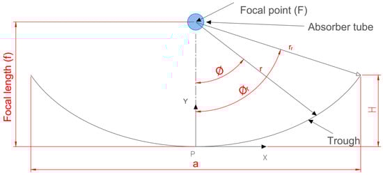
Figure 1.
A common parabolic trough collector in 2D section.
The following is a mathematical explanation of the various geometrical parameters. The following Equation (1), which is symmetric about the y-axis and uses f as the parabola’s focal length, is an analytical version of a parabola equation [23,24]. Adding to the parabola Equation (1) yields the equation for PTC height (),which is as follows:
A parabolic trough’s size, shape, and curvature are determined by its focal length (f), aperture width (a), and rim angle (), and the relationship between these parameters is as follows [25]:
The rim angle can also be determined as follows [26]:
The aperture area () and effective aperture area are determined using the following relationships [27]:
where is the absorber tube’s outer diameter, and is the trough length.
The surface area () of the concentrator can be calculated using the following equation [25]:
The trough radius () at any local point is obtained by the following Equation (8) [28,29]:
The value of the geometrical concentration ratio , which denotes the system’s capacity to concentrate solar energy, ranges from the unity to 105. Its value is 1 for the evacuated tube and flat collectors of non-focusing systems; however, it can reach 100 for parabolic trough (line-focusing) collectors. A value up to 1000 can be reached by point-focusing systems (dish collectors). The following equation [27] provides the collector’s concentration ratio:
3. Materials and Methods
3.1. System Specification
The solar cooker was designed as a box. Additionally, the cooker’s thermal performance was enhanced. The study was conducted throughout August 2023 from 9:00 to 16:00 in Egypt (latitude: 30°11′ N, longitude: 31°24′ E). The system consists of a parabolic trough collector (PTC) and a box solar cooker. To optimize the heat gained, the cooker was provided with a solar collector. The collector had a 30-degree slant. The working fluid was circulated throughout the solar cooker using an electrical pump, with a closed loop of the working fluid. After the electric pump, a straightforward valve was placed to regulate the flow rate. Additionally, a thermometer type K was used for recording the temperature of the working fluid both within and outside of the system and the ambient temperature.
3.1.1. The Parabolic Trough Collector’s Characteristics
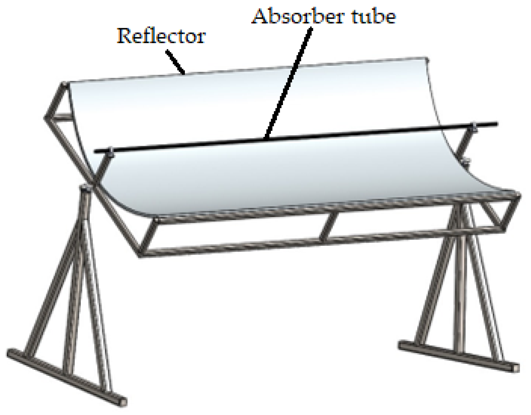
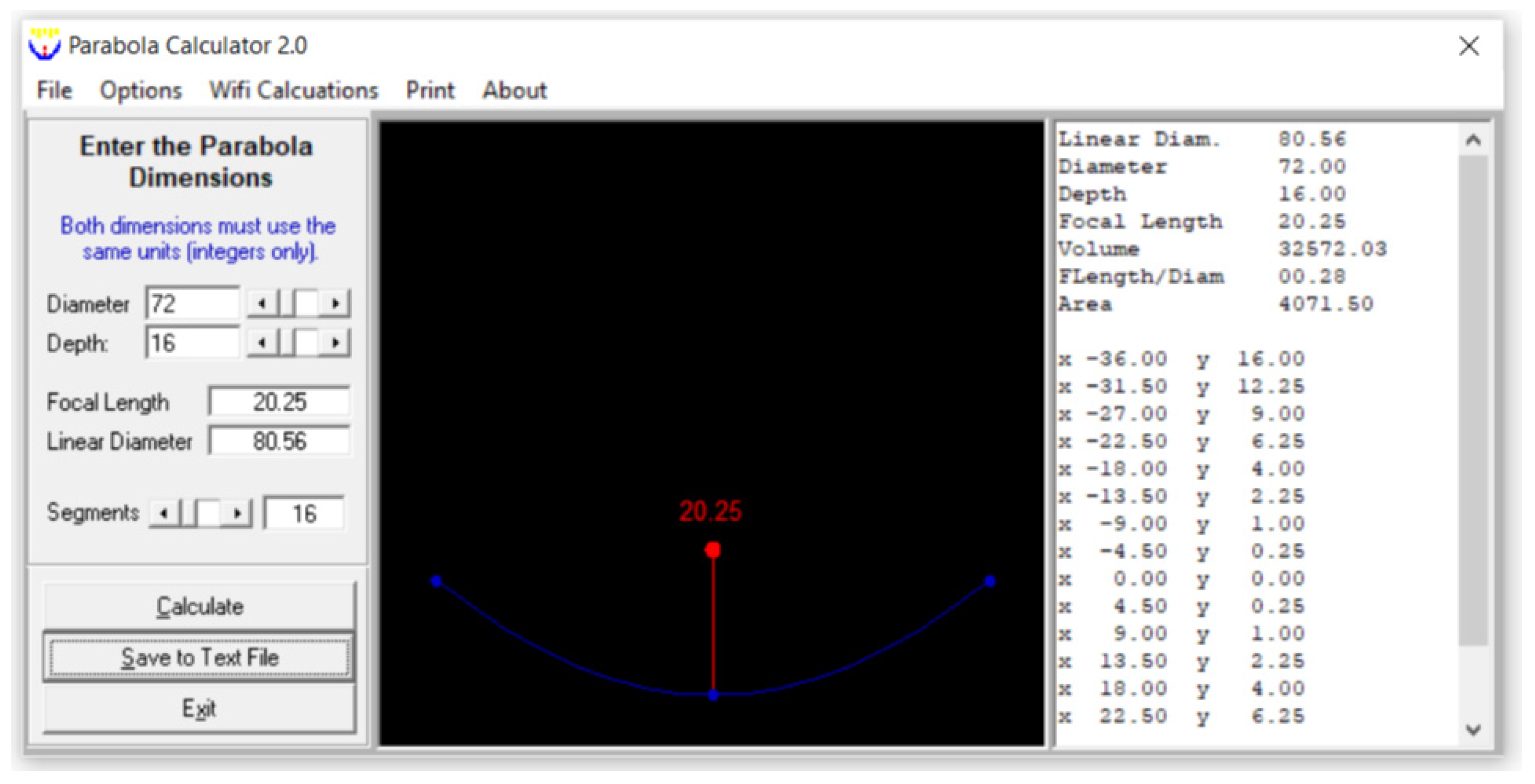
A PTC has been used in many solar thermal studies and applications [12,27,28]; so, a PTC was used in this study. A schematic view of the PTC is shown in Figure 2, which was created in SolidWorks2023. The absorber tube and the reflector are this collector’s principal components. Water, GO (250 ppm)-water, and GO (500 ppm)-water were used as the heat transfer fluids. Its interior surface was covered with polished stainless steel, 0.4 mm thick and 2 m long, which served to reflect and concentrate the sun radiation into a straight line. A 16 mm diameter copper tube was located on the axis line of the PTC to collect the maximum amount of reflected solar radiation. The copper tube was painted matte black to absorb maximum solar energy. The parabola trough was modeled by entering the diameter (also known as the aperture) and height (also known as the depth) of the parabola in the Parabola Calculator 2.0 program (Figure 3). In this method, the number of segments selected determines how many coordinate points on the curve are provided by the parabola calculator software.
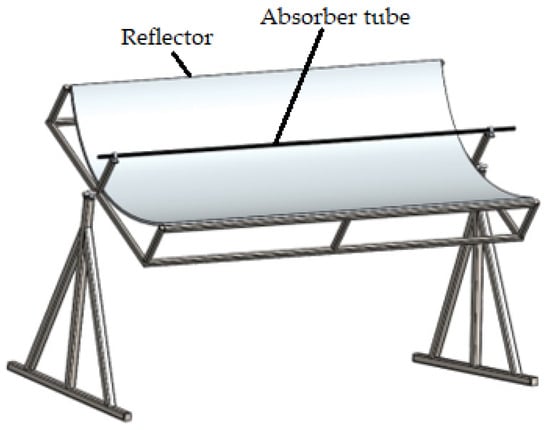
Figure 2.
Schematic view of the PTC.
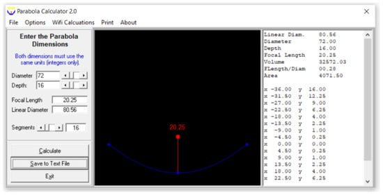
Figure 3.
A screenshot of a parabola created using the Parabola Calculator 2.0 program.
3.1.2. The Box Solar Cooker ‘s Specifications
Wood was used to construct the solar cooker, as shown in Figure 4. Its dimensions were 60, 50, and 50 cm for length, width, and height, respectively. The front side was inclined by 30 degrees. To reflect sunlight onto the absorber plate, the inside sides were covered with 0.4 mm thick polished stainless steel. According to [2], the sloped side was equipped with a double glass cover of 4 mm, with the glasses being 2 cm apart. A layer of glass wool, 5 cm thick, served as insulation for the absorber plate’s bottom and outsides as shown in Figure 4b. The 0.3 m2 aluminum heat absorber plate had a matte black paint coating. A copper tube that was matte-black paint-coated and with a serpentine shape with dimensions of 12 mm, 0.1 mm and 2 m for outside diameter, thickness, and length, respectively, was in contact with it. The cooking pot was flat-bottomed, cylindrical, and constructed of aluminum that had been matte-black paint-coated. It measured 21 cm in diameter, 11.5 cm in height, and 0.27 cm in thickness. It was positioned in the middle of the cooker box’s absorber plate.
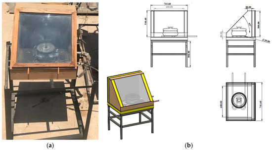
Figure 4.
Photograph (a) and schematic view (b) of the box solar cooker.
To evaluate the effectiveness of the suggested system, some parameters, including water temperature in the cooking pot, ambient air temperature, and solar radiation, were measured and averaged over the entire period. The solar cooker’s cooking pot was filled with 200, 600, and 1000 g of rice to test its cooking properties. To cook a certain amount of rice required 1.5 times as much water [30].
3.2. Preparation of Graphene Oxide Nanosheets
3.2.1. Synthesis of Graphene Oxide (GO) Nanosheets
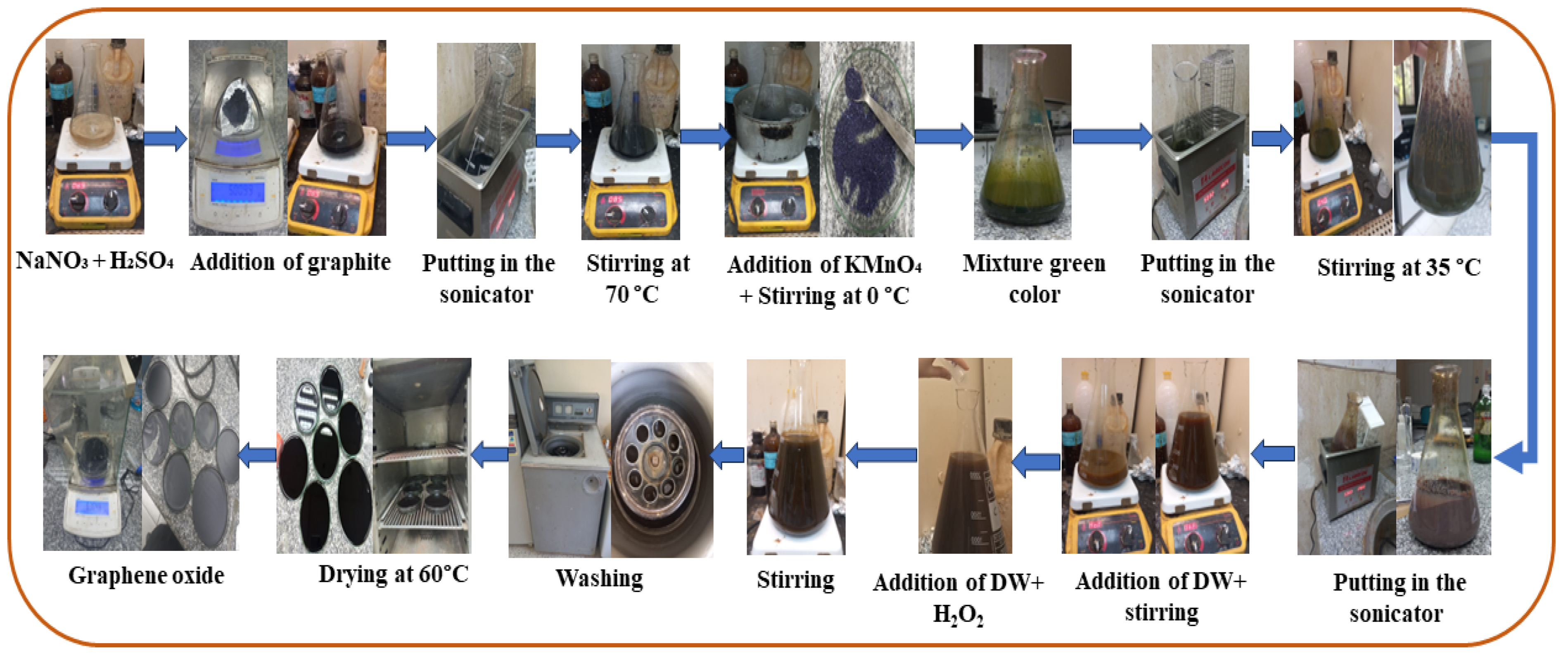
GO nanosheets were made using the modified Hammers method, as shown in Figure 5. We placed 5 g of NaNO3 and 250 mL of H2SO4 (98%) in a 1 L flask and stirred the mixture at 70 °C until NaNO3 was completely dissolved. Then, the mixture was mixed with 5 g of graphite, put in hot water in a sonicator for 1 h, and stirred at 70 °C for 45 min. Then, the stirrer’s heater was turned off, and stirring continued for 24 h at room temperature. After putting the flask in an ice water bath at 0 °C, 30 g of KMnO4 was gradually added, and stirring was maintained for 30 min at 0 °C. (The color of the observed mixture was green). The resulting solution was stirred at 35 °C for 5 h. After this, the flask was placed in hot water in the sonicator and sonicated for 1 h; then, the solution was transferred to a 2 L flask. At this point, 460 mL of deionized (DI) water was slowly added to the solution, with continuous stirring. The flask was placed on the stirrer (the color of the mixture was dark brown), and the mixture was stirred for one hour at 98 °C (the color of the mixture changed to brown). The reaction was then terminated by adding 1400 mL of deionized water and 50 mL of hydrogen peroxide (5% H2O2) to the mixed solution in sequence. The final substance was repeatedly filtered with distilled water. Brown GO nanosheets were made by drying this material in an oven at 60 °C for 12 h.
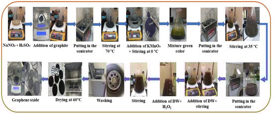
Figure 5.
Flowchart of GO preparation.
3.2.2. XRD Examination of GO
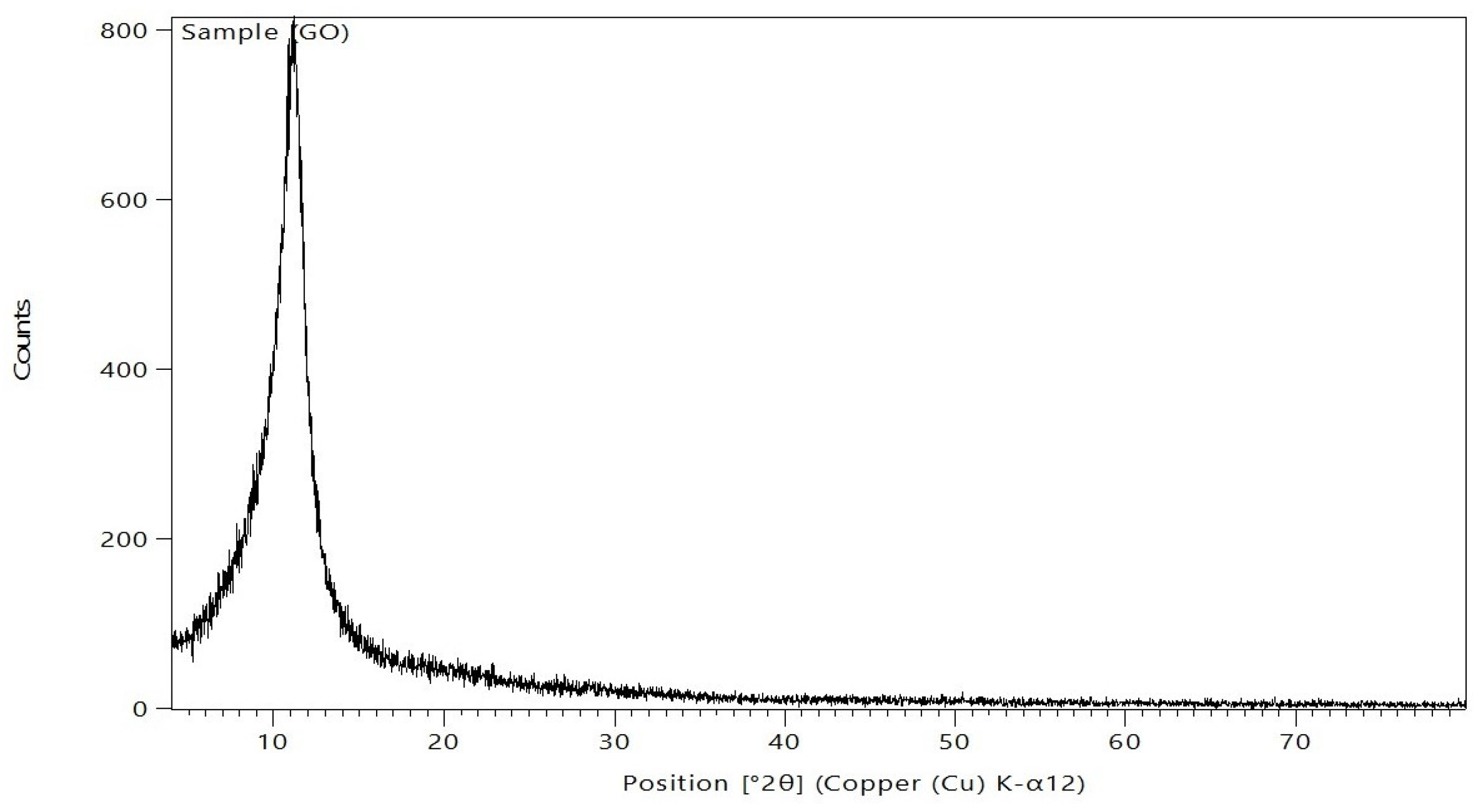
After being ground into powder, the produced GO samples were distributed as equally as possible throughout the sample preparation area. Subsequently, the powders were gently compressed using a small spatula, and the excess bulge powders were peeled off using a razor blade (or slide fracture) to obtain an extremely flat plane of the sample powders. The corresponding XRD pattern was recorded in the scanning mode (X ’pert PRO, PAN analytical, Netherlands) operated by Cu K radiation tube (=1.54 A°) at 40 kV and 30 mA. The obtained diffraction pattern was interpreted by the standard ICCD library installed in PDF4 software. The composition of GO was analyzed by XRD; the results are displayed in Figure 6. Following Bragg’s law, the GO XRD spectrum revealed a clear, sharp peak at 2θ = 11.14°, which is the characteristic peak of pure GO, as reported previously [31,32]. This peak is mostly caused by inter-lamellar water trapped between the GO nanosheets.
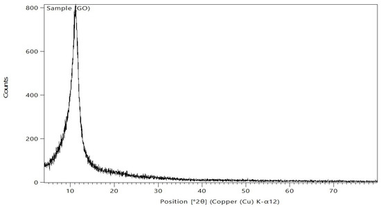
Figure 6.
The XRD of the GO nanosheets.
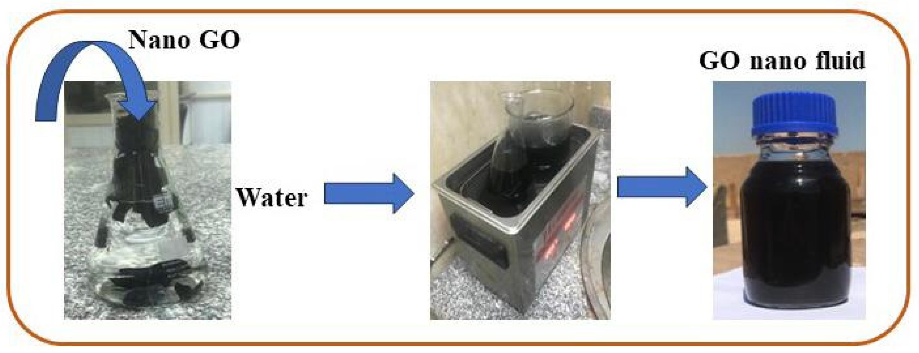
3.3. GO Nanofluid Preparation
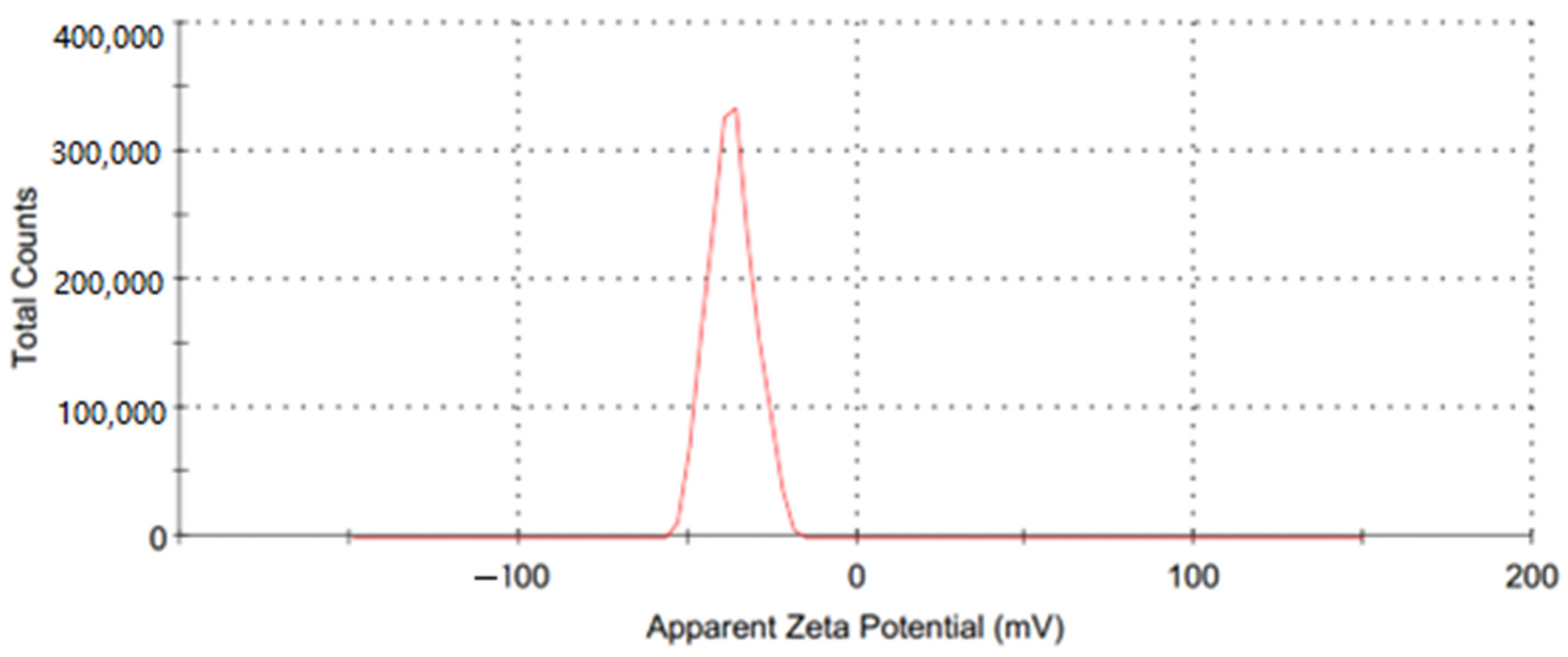
A water-based GO nanofluid was used as the working fluid in this investigation. A two-step procedure was used for its preparation, and GO nanoparticles (250 ppm and 500 ppm) were added to water; the preparation was then placed in hot water in the sonicator for about 90 min. Figure 7 depicts the steps involved in the preparation of the GO-water nanofluid. Utilizing a zeta potential machine (Nano-zeta sizer (Malvern, ZS Nano, UK)), the stability of the GO-water nanofluid was tested. According to Verma et al. [33], measuring the mean zeta potential voltage difference provide an indication of a system’s stability, and their findings state that a fluid is deemed stable enough if its mean zeta potential is greater than ±25 mV. The zeta potential in the current work was −36.9 mV, as Figure 8 illustrates, ensuring a stable fabrication of the GO-water nanofluid.

Figure 7.
Diagram for preparing the GO nanofluid.
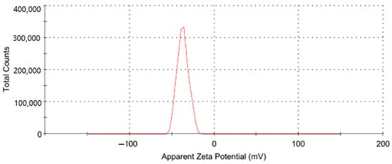
Figure 8.
The zeta potential of the GO nanofluid.
The following equations were used to determine the nanofluid’s heat capacity, density, and thermal conductivity [34]. Table 1 displays the nanofluids’ thermal characteristics.

Table 1.
The thermal properties of the GO nanofluid.
3.4. System Evaluation
3.4.1. Stagnation Temperature Test (First Figure of Merit F1)
F1 was estimated under no load. F1 was calculated by the following equation, as reported by [36]:
3.4.2. Estimating the Second Figure of Merit F2
The F2 achieved by heating the water-filled containers on the absorbent plate can be expressed mathematically as [36]:
3.4.3. Energy Analysis
The input and output energies were utilized to determine the system’s thermal performance in cooking. For data reduction, the following equations were utilized.
The input energy was determined by Equation (15):
The following expression describes the energy output, or the energy used for cooking:
Using the following equation [34], the solar cooker’s energy efficiency was computed:
3.4.4. Exergy Analysis
The solar cooker’s exergy input was determined by the following expression [34]:
In contrast, the exergy output was determined as follows [34]:
Equation (20) was used to calculate the solar cooker’s exergy efficiency [34]:
3.5. Textural Analysis
Textural properties play an important role in the consumption of rice. The texture characteristics of cooked rice were investigated using a uniaxial single-compression method with the Tinius Olsen’s bench top materials testing machine model H5ks, U.S.A. A cylindrical probe with a 25 mm diameter was utilized to crush the kernels in cooked rice. As per [37], the test speed was 1 mm/s. The force needed to crush the rice was used to measure the rice hardness and is represented by the peak force of the texture profile curve. The hardest rice was identified by measuring the greatest force and the distance needed to break off a sample. A mean value derived from ten replications is presented.
4. Results
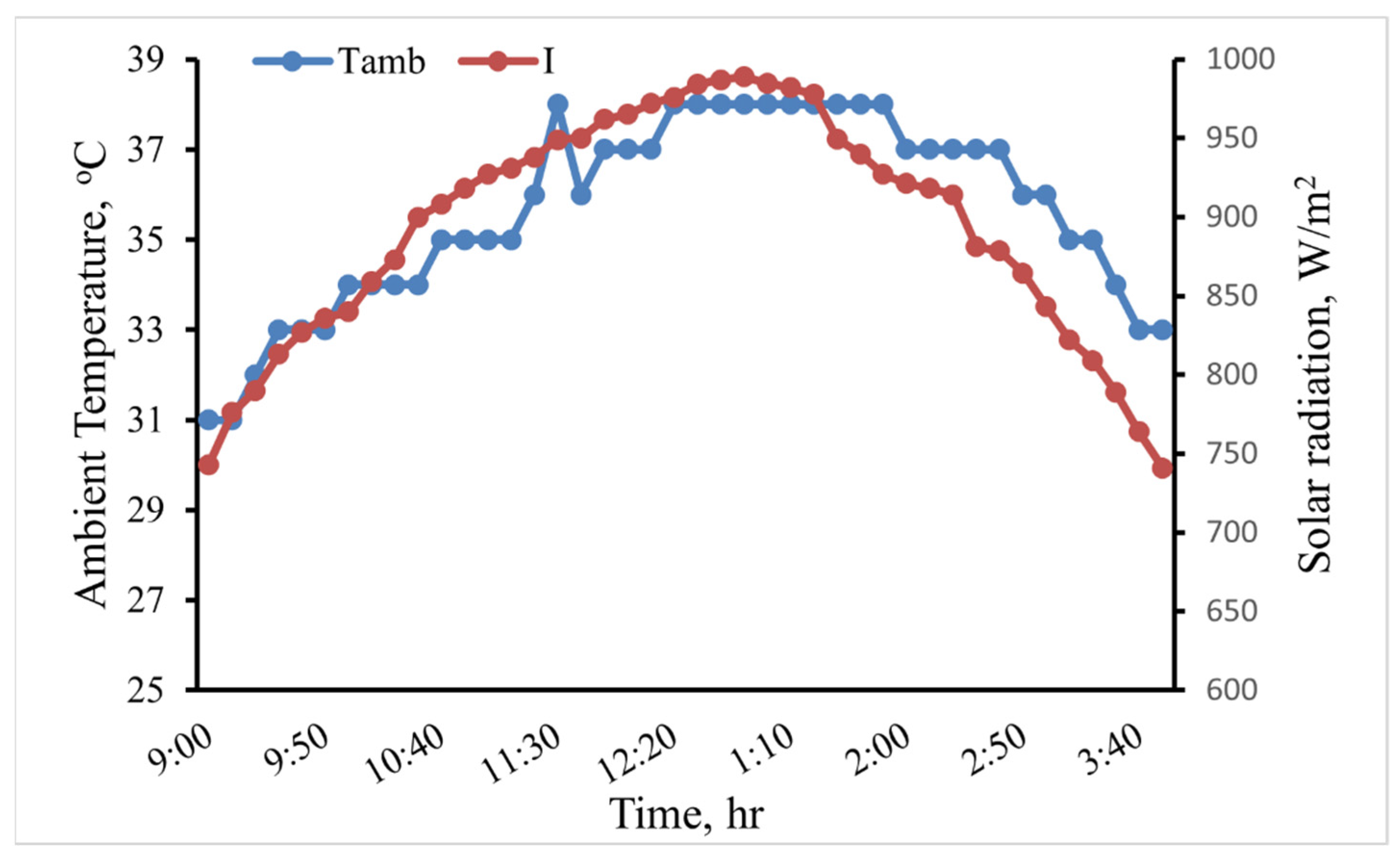
This study evaluated through experimentation how various heat transfer fluids affected an indirect solar cooker’s performance. Three fluids—water, GO (250 ppm)-water, and GO (500 ppm)-water—were the focus of the heat transfer study. The experiments were conducted in August at the Ain Shams University’s Faculty of Agriculture in Egypt. Figure 9 depicts the variance in the weather for the scenario where water was used as the heat transfer fluid. The figure indicates that during the test period, the average solar radiation (I) and ambient temperature (Tamb) were 888.41 W/m2 and 35.51 °C, respectively. The average I and Tamb for each heat transfer fluid are shown in Table 2. The experiments were conducted under roughly similar weather conditions, as shown in Table 2.

Figure 9.
The variation of I and Tamb in the case of water as the heat transfer fluid.
Table 2.
The average I and Tamb for the different fluids tested in this study.
4.1. Figures of Merits
The average F1 value was 0.1 for the base fluid water, 0.11 for GO (250 ppm)-water, and 0.13 for GO (500 ppm)-water. Good optical efficiency and a low heat loss factor for the absorber plate are indicated by the a value of F1. The average F2 value was 0.24 for the base fluid water, 0.38 for GO (250 ppm)-water, and 0.52 for GO (500 ppm)-water. In comparison to a full load of water, a high value for F2 indicates that a cooker has a good heat-exchange efficiency factor, good optical efficiency, and a low heat capacity in the interior and pans. Both F1 and F2 were higher for the solar cooker with GO (500 ppm)-water than for the other systems.
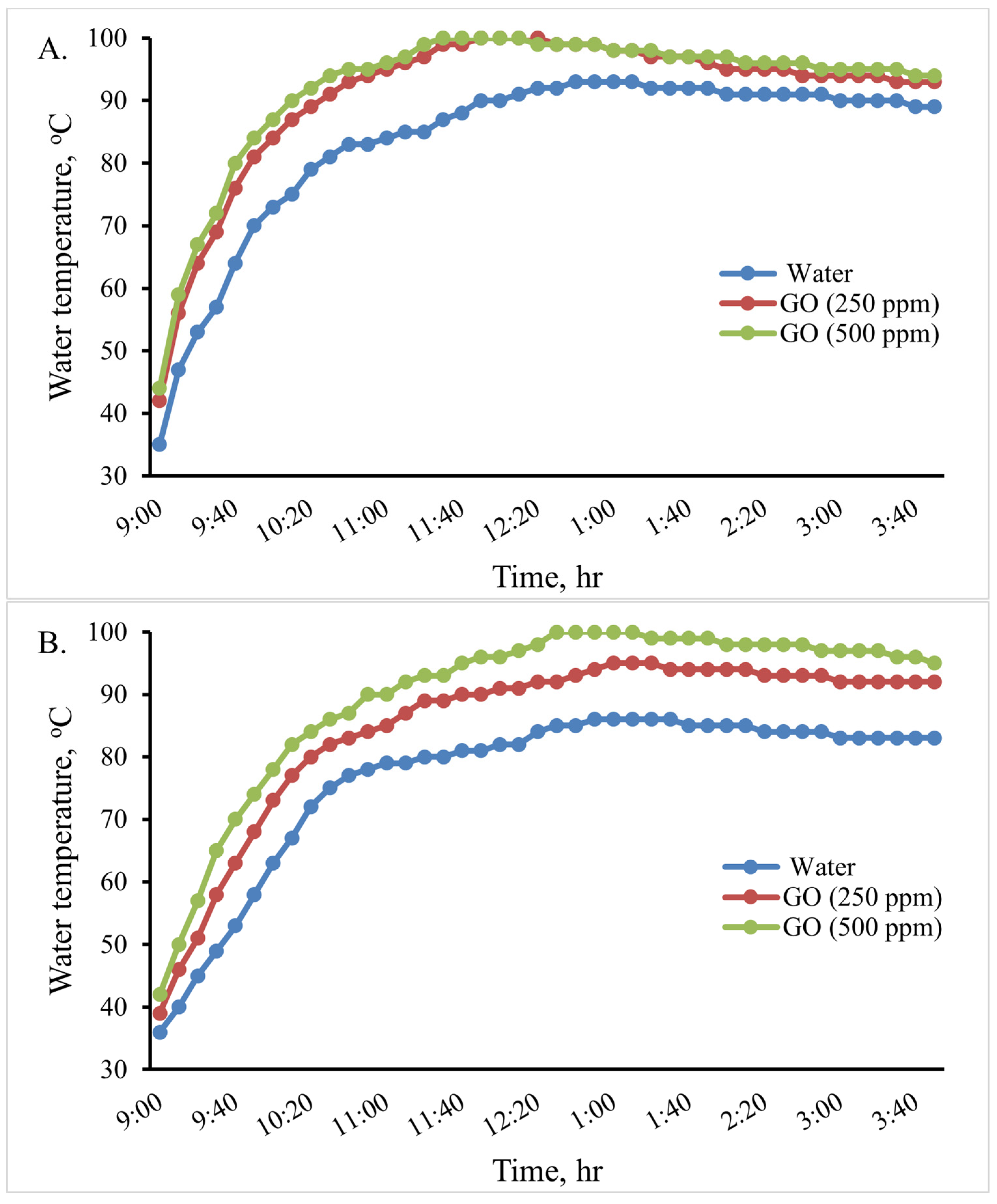
In this experiment, an indirect solar cooker was used to heat 0.5, 1.0, and 2 L of water. The water temperature variation in the cooker in the various scenarios is shown in Figure 10. When using 2 L, the maximum water temperature reached in the cooker was 81 °C at 1:10 Pm, 90 °C at 1:00 Pm, and 97 °C at 12:40 Pm for the base fluid water, GO (250 ppm)-water, and GO (500 ppm)-water, respectively. Therefore, when using the GO (500 ppm)-water nanofluid instead of water in the indirect solar cooker, the temperature of water increased by about 16 °C (19.75%). When using 1 L, the maximum water temperature reached in the cooker was 86 °C at 1 Pm and 94 °C at 1 Pm for the base fluid water and GO (250 ppm)-water, while water boiled at 12:40 Pm for GO (500 ppm)-water. When using 0.5 L, the maximum water temperature reached in the cooker was 93 °C at 12:50 for the base fluid water, while water boiled at 12:10 Pm and at 11:40 Pm for GO (250 ppm)-water and GO (500 ppm)-water, respectively. The thermal performance of the GO (500 ppm)-water nanofluid can be considered good. Therefore, the GO (500 ppm)-water nanofluid could be used instead of water in the solar cooker to boil water; so, the rice cooking operations were carried out using it.
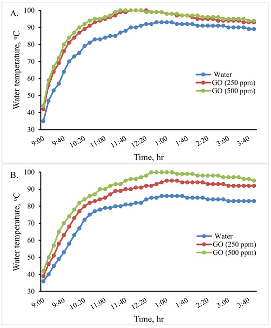
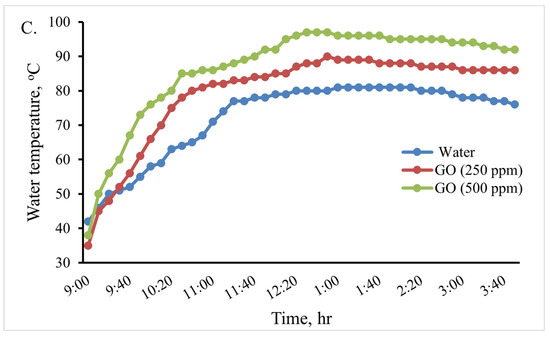
Figure 10.
Variations in the cooking unit’s water temperature in the various examined scenarios with 0.5 (A), 1.0 (B), and 2.0 (C) liters of water.
4.2. Energy Analysis of the Cooking Unit
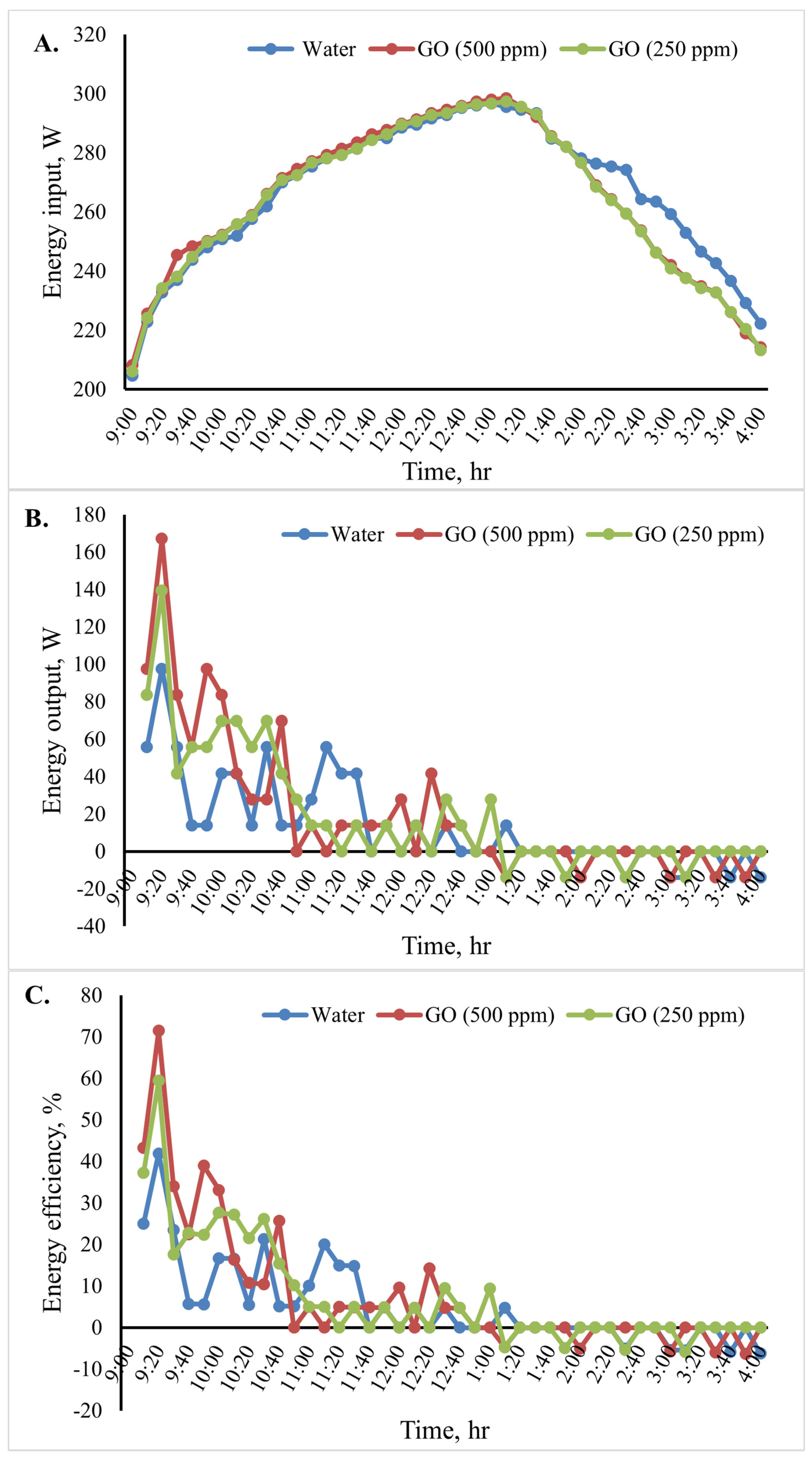
The cooking unit’s input, output, and energy efficiency variation for the various heat transfer fluids is shown in Figure 11. The average energy input in Figure 11A and energy outputs in Figure 11B for the 10 min time interval were determined. In a specific case, the water temperature variation indicated that the cooking unit’s output energy rose at the start of the test period and fell after 20 min. Among the studied cases examined, Figure 11B shows that the cooking unit’s maximum output energy was 167.2 W for the system with the GO (500 ppm)-water nanofluid.
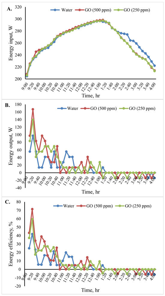
Figure 11.
Energy analysis of the cooking unit: (A) energy input,(B) energy output, and (C) energy efficiency versus time for 2 L of water.
Additionally, the cooking unit’s average output energy during the test period was 139.3 W for water and 97.5 W for GO (250 ppm)-water. The cooking unit’s energy efficiency during the test period is shown in Figure 11C. The obtained results clearly show that the energy efficiency was high initially and then decreased over time because the energy is directly proportional to the temperature difference of water. When utilizing the nanofluids in the indirect solar cooker instead of water, the cooking unit’s average energy efficiency increased, as seen in Figure 11C. The cooking unit’s average energy efficiency in the system with the GO (500 ppm)-water nanofluid was 71.4%. Furthermore, the average energy efficiency for the system with water was found to be approximately 41.9%. In Figure 11B,C, it is shown that the curve presents oscillations at first because the difference in water temperature increased or decreased significantly with time (every 10 min) until it reached stability (the change in water temperature was equal to zero). When output energy and efficiency equal zero, the water temperature inside the cooker is constant. Negative values indicate that the cooker is losing heat.
4.3. Exergy Analysis of the Cooking Unit
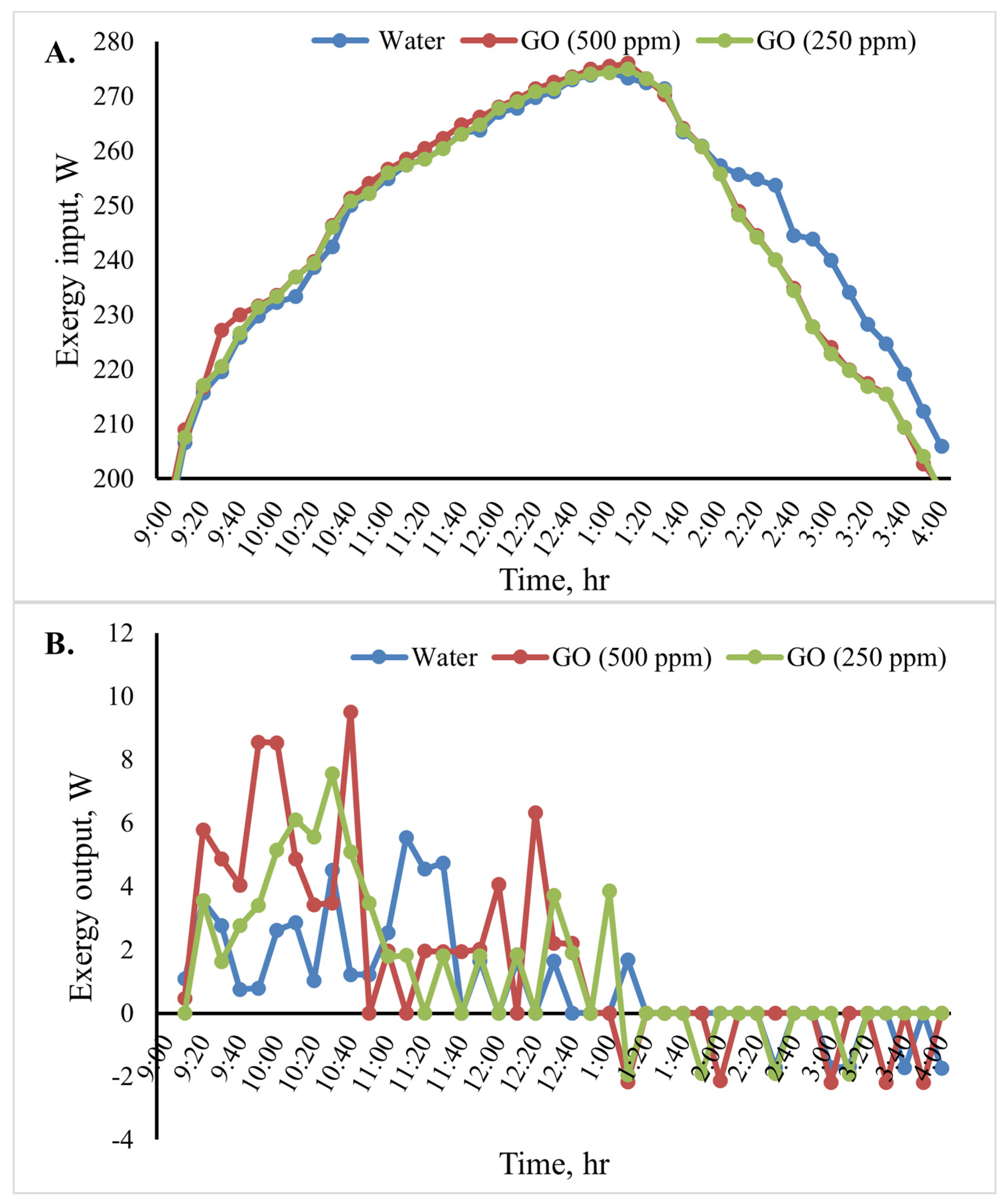
Figure 12 shows the cooking unit’s input, output, efficiency, and exergy change over time for the various heat transfer fluids. Based on the results shown in Figure 12B, throughout the test period, the cooking unit’s average output exergy was 5.5, 7.5, and 9.5 W for the heat transfer fluids water, GO (250 ppm)-water, and GO (500 ppm)-water, respectively. The average exergy efficiency of the cooking unit in the various scenarios over time is shown in Figure 12C. The results of the analyses show that when using the nanofluids, the cooking unit’s average output and exergy efficiency were higher than those of the water-based system. The average exergy efficiency of the cooking unit in the system with the GO (500 ppm)-water nanofluid was 3.1%, as shown in Figure 12. Furthermore, the average exergy efficiency for water was found to be roughly 2.1%.
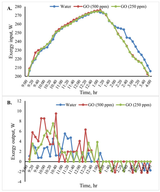
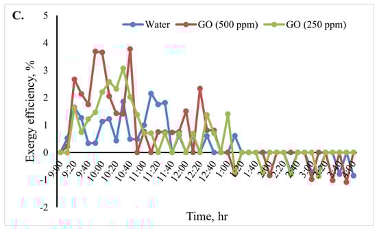
Figure 12.
Exergy analysis of the cooking unit: (A) exergy input, (B) exergy output, and (C) exergy efficiency versus time for 2 L of water.
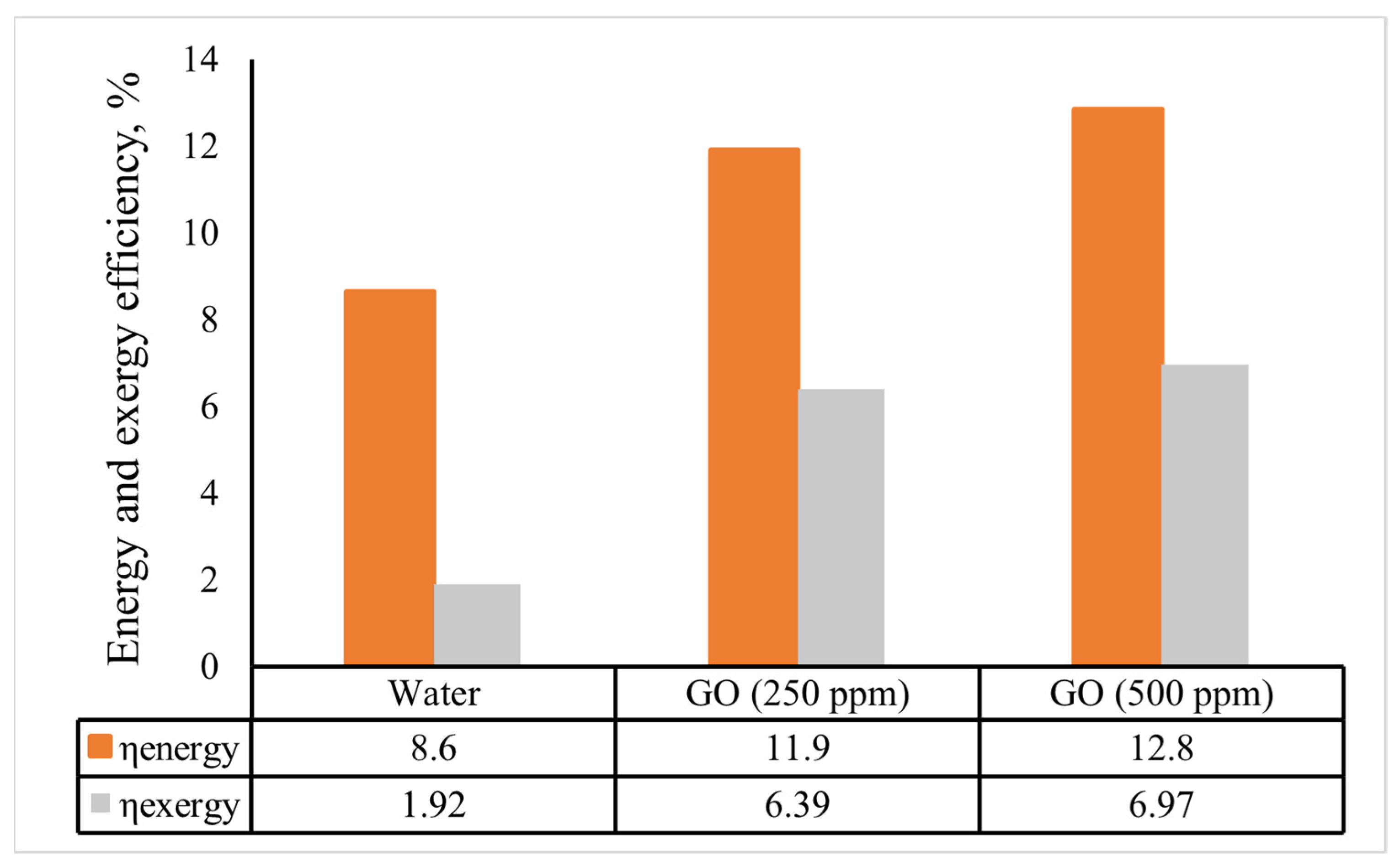
Figure 13 displays the indirect solar cooker’s overall energy and exergy efficiencies for the various heat transfer fluids. The overall energy and exergy efficiencies of the solar cooker based on the GO (500 ppm)-water nanofluid were 12.8% and 6.97%, respectively. The average overall energy efficiency of the solar cooker improved by 3.3 and 4.2 percentage points when the GO (250 ppm)-water and GO (500 ppm)-water nanofluids were used instead of water. Additionally, a comparable improvement of 4.47 and 5.1 percentage points was attained for the average of the overall exergy efficiency. Kumaresan et al. [38] used a flat-plate cooking unit intended for the indirect mode of solar cooking and found the overall energy efficiency was 9, while Hosseinzadeh et al. [6] discovered that a solar cooker using thermal oil and nanofluids in 0.2 and 0.5 wt% had overall energy efficiency values of 12.85%, 15.93%, and 20.08%, respectively. Additionally, the total exergy efficiency of nanofluid-based solar cookers with 0.2 wt% and 0.5 wt% of the nanofluids improved even more compared to that of the cooker using thermal oil, by 37.30% and 65.87%, respectively. Furthermore, the nanofluid-based indirect solar cookers had better output thermal power and output thermal exergy rate in comparison with the cooker with thermal oil or water, due to the superior outputs of thermal energy and exergy.
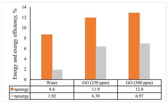
Figure 13.
The indirect solar cooker’s average energy and exergy efficiencies in various scenarios.
4.4. Quantities of Rice Required for a Family and Texture Analysis
A cooking test was conducted in August using 200, 600, and 1000 g of rice. To calculate the total quantity of rice required for a middle-sized family was considered. An adult needs 300 g of rice, and a child needs 100 g. Table 3 illustrates how much cooked rice is needed for each member of the family, as well as how long it takes to cook it.
Table 3.
The amount of time needed to cook various amounts of rice in the cooker.
Texture reflects rice hardness. Physically, the hardness of cooked rice is defined as its ability to withstand a specific load at a given time. Texture analysis can determine the hardness and tenderness of rice. According to this research, the average texture of cooked rice was from 24.6 to 28 gf. The results of cooked rice hardness agree with those of Syafutri et al. [32].
5. Conclusions
Experiments were conducted in this study to assess the performance of a solar cooker with different heat transfer fluids including water, GO (250 ppm)-water, and GO (500 ppm)-water nanofluids. The following is a list of the conclusions drawn from the research:
- The solar cooker with the GO (500 ppm)-water nanofluid had energy and exergy efficiencies of 12.8% and 6.97%, respectively. Moreover, the solar cooker with GO (500 ppm)-water showed superior performance.
- Using the GO (250 ppm)-water and GO (500 ppm)-water nanofluids in the indirect solar cooker enhanced the average overall energy efficiency of the solar cooker by 3.3% and 4.2% compared to that of a system with water, respectively. Moreover, the corresponding enhancement in the average of the overall exergy efficiency was found to be of 4.47 and 5.1 percentage points, respectively.
According to the results, the use of the GO-water nanofluid is appropriate to improve the performance of indirect solar cookers. Thus, future research should focus on the effect of the simultaneous use of nanofluids and PCMs on the thermal performance of indirect solar cookers.
Author Contributions
Conceptualization, F.M.S., M.F.A.-S. and M.F.A.; writing, original draft preparation, F.M.S.; data processing and analysis, F.M.S., M.F.A.-S., K.Y.F. and M.F.A.; review and editing, M.F.A.-S., M.F.A., H.W. and K.Y.F. All authors have read and agreed to the published version of the manuscript.
Funding
This research received no specific grant from any funding agency in the public, commercial, or not-for-profit sectors.
Institutional Review Board Statement
The manuscript was reviewed and ethically approved for publication by all authors.
Informed Consent Statement
The manuscript was reviewed, and all authors consented to participate.
Data Availability Statement
Data and materials are available upon request from the authors.
Conflicts of Interest
The authors declare no financial or non-financial conflicts of interest.
Nomenclature
| PTC | Parabolic trough collector |
| x | Horizontal axis |
| y | Vertical axis |
| f | Focal length (m) |
| H | Height of the trough (m) |
| a | Aperture width (m) |
| Rim angle (in degree) | |
| Radius of the rim (m) | |
| Aperture area (m2) | |
| Outer diameter of the absorber tube (m) | |
| Length of the absorber tube (m) | |
| Length of the trough (m) | |
| Surface area (m2) | |
| Geometrical concentration ratio | |
| Input energy | |
| ULS | Heat loss factor (W/°C·m2) |
| I | Intensity of solar radiation (Wm−2) |
| Aperture area of the cooker | |
| Energy output | |
| Mass of water (kg) | |
| Specific heat of water (J/kg·°C) | |
| Final temperature of water (°C or K) | |
| Initial temperature of water (°C or K) | |
| Time period (s) | |
| Energy efficiency | |
| Input exergy | |
| Output exergy | |
| Tamb | Ambient temperature (°C or K) |
| Exergy efficiency | |
| Solar surface temperature on Earth’s surface, (K) | |
| Absorber plate temp. (°C) | |
| t1, t2 | Time to reach a certain water temperature, and in (°C) |
References
- Suman, S.; Khan, M.K.; Pathak, M. Performance enhancement of solar collectors—A review. Renew. Sustain. Energy Rev. 2015, 49, 192–210. [Google Scholar] [CrossRef]
- Saxena, A.; Varun; Pandey, S.P.; Srivastav, G. A thermodynamic review on solar box type cookers. Renew. Sustain. Energy Rev. 2011, 15, 3301–3318. [Google Scholar] [CrossRef]
- Panwar, N.L.; Kaushik, S.C.; Kothari, S. Role of renewable energy sources in environmental protection: A review. Renew. Sustain. Energy Rev. 2011, 15, 1513–1524. [Google Scholar] [CrossRef]
- Sandeep, H.M.; Arunachala, U.C. Solar parabolic trough collectors: A review on heat transfer augmentation techniques. Renew. Sustain. Energy Rev. 2017, 69, 1218–1231. [Google Scholar] [CrossRef]
- Gong, X.; Wang, F.; Wang, H.; Tan, J.; Lai, Q.; Han, H. Heat transfer enhancement analysis of tube receiver for parabolic trough solar collector with pin fin arrays inserting. Sol. Energy 2017, 144, 185–202. [Google Scholar] [CrossRef]
- Hosseinzadeh, M.; Sadeghirad, R.; Zamani, H.; Kianifar, A.; Mirzababaee, S.M.; Faezian, A. Experimental study of a nanofluid-based indirect solar cooker: Energy and exergy analyses. Sol. Energy Mater. Solar Cells 2021, 221, 110879. [Google Scholar] [CrossRef]
- Bekele, A.; Dereje, S.; Pandey, V.; Badruddin, I.A. Experimental Investigation of Parabolic Dish Solar Collector using Nanofluids for Steam Cooking. Arab. J. Sci. Eng. 2023, 49, 2581–2597. [Google Scholar] [CrossRef]
- Abd-Elhady, M.S.; Abd-Elkerim, A.N.A.; Ahmed, S.A.; Halim, M.A.; Abu-Oqual, A. Study the thermal performance of solar cookers by using metallic wires and nanographene. Renew. Energy 2020, 153, 108–116. [Google Scholar] [CrossRef]
- Oommen, R.; Jayaraman, S. Development and performance analysis of compound parabolic solar concentrators with reduced gap losses—Oversized reflector. Energy Convers. Manag. 2001, 42, 1379–1399. [Google Scholar] [CrossRef]
- Mawire, A.; McPherson, M.; Van Den Heetkamp, R.R.J. Simulated energy and exergy analyses of the charging of an oil–pebble bed thermal energy storage system for a solar cooker. Sol. Energy Mater. Sol. Cells 2008, 92, 1668–1676. [Google Scholar] [CrossRef]
- El Moussaoui, N.; Talbi, S.; Atmane, I.; Kassmi, K.; Schwarzer, K.; Chayeb, H.; Bachiri, N. Feasibility of a new design of a Parabolic Trough Solar Thermal Cooker (PSTC). Sol. Energy 2020, 201, 866–871. [Google Scholar] [CrossRef]
- Noman, M.; Wasim, A.; Ali, M.; Jahanzaib, M.; Hussain, S.; Ali, H.M.K.; Ali, H.M. An investigation of a solar cooker with parabolic trough concentrator. Case Stud. Therm. Eng. 2019, 14, 100436. [Google Scholar] [CrossRef]
- Azmi, W.H.; Sharma, K.V.; Sarma, P.K.; Mamat, R.; Anuar, S. Comparison of convective heat transfer coefficient and friction factor of TiO2 nanofluid flow in a tube with twisted tape inserts. Int. J. Therm. Sci. 2014, 81, 84–93. [Google Scholar] [CrossRef]
- Mehrali, M.; Sadeghinezhad, E.; Rosen, M.A.; Latibari, S.T.; Mehrali, M.; Metselaar, H.S.C.; Kazi, S.N. Effect of specific surface area on convective heat transfer of graphene nanoplatelet aqueous nanofluids. Exp. Therm. Fluid Sci. 2015, 68, 100–108. [Google Scholar] [CrossRef]
- Bharadwaj, G.; Sharma, K.; Pandey, A.K.; Gupta, A. Carbon nanotube–graphene-based nanofluids: A comprehensive review on the role of thermal conductivity and its solar energy applications. J. Therm. Anal. Calorim. 2024, 2024, 1–35. [Google Scholar] [CrossRef]
- Prabu, A.S.; Chithambaram, V.; Muthucumaraswamy, R.; Shanmugan, S. Experimental investigations on the performance of solar cooker using nichrome heating coil—Photovoltaic with microcontroller PIC 16F877A. Environ. Prog. Sustain. Energy 2023, 42, e14028. [Google Scholar] [CrossRef]
- Papade, C.V.; Kanase-Patil, A.B. Characterization of nano-mixed PCM for solar cooker application. Mater. Today Proc. 2023. [Google Scholar] [CrossRef]
- Subramani, J.; Nagarajan, P.K.; Wongwises, S.; El-Agouz, S.A.; Sathyamurthy, R. Experimental study on the thermal performance and heat transfer characteristics of solar parabolic trough collector using Al2O3 nanofluids. Environ. Prog. Sustain. Energy 2018, 37, 1149–1159. [Google Scholar] [CrossRef]
- Coccia, G.; Di Nicola, G.; Colla, L.; Fedele, L.; Scattolini, M. Adoption of nanofluids in low-enthalpy parabolic trough solar collectors: Numerical simulation of the yearly yield. Energy Convers. Manag. 2016, 118, 306–319. [Google Scholar] [CrossRef]
- Mwesigye, A.; Huan, Z.; Meyer, J.P. Thermodynamic optimisation of the performance of a parabolic trough receiver using synthetic oil–Al2O3 nanofluid. Appl. Energy 2015, 156, 398–412. [Google Scholar] [CrossRef]
- Bellos, E.; Tzivanidis, C.; Antonopoulos, K.A.; Gkinis, G. Thermal enhancement of solar parabolic trough collectors by using nanofluids and converging-diverging absorber tube. Renew. Energy 2016, 94, 213–222. [Google Scholar] [CrossRef]
- Farhana, K.; Kadirgama, K.; Rahman, M.M.; Ramasamy, D.; Noor, M.M.; Najafi, G.; Samykano, M.; Mahamude, A.S.F. Improvement in the performance of solar collectors with nanofluids—A state-of-the-art review. Nano-Struct. Nano-Objects 2019, 18, 100276. [Google Scholar] [CrossRef]
- Price, H.; Lu¨pfert, E.; Kearney, D.; Zarza, E.; Cohen, G.; Gee, R.; Mahoney, R. Advances in Parabolic Trough Solar Power Technology. J. Sol. Energy Eng. 2002, 124, 109–125. [Google Scholar] [CrossRef]
- Menbari, A.; Alemrajabi, A.A.; Rezaei, A. Experimental investigation of thermal performance for direct absorption solar parabolic trough collector (DASPTC) based on binary nanofluids. Exp. Therm. Fluid Sci. 2017, 80, 218–227. [Google Scholar] [CrossRef]
- Upadhyay, B.H.; Patel, A.J.; Sadasivuni, K.K.; Mistry, J.M.; Ramana, P.V.; Panchal, H.; Ponnamma, D.; Essa, F.A. Design, development and techno economic analysis of novel parabolic trough collector for low-temperature water heating applications. Case Stud. Therm. Eng. 2021, 26, 100978. [Google Scholar] [CrossRef]
- Sup, B.A.; Zainudin, M.F.; ZanariahShamsirAli, T.; Bakar, R.A.; Ming, G.L. Effect of Rim Angle to the Flux Distribution Diameter in Solar Parabolic Dish Collector. Energy Procedia 2015, 68, 45–52. [Google Scholar] [CrossRef]
- Faheem, M.; Jizhan, L.; Akram, M.W.; Khan, M.U.; Yongphet, P.; Tayyab, M.; Awais, M. Design optimization, fabrication, and performance evaluation of solar parabolic trough collector for domestic applications. Energy Sources Part A Recovery Util. Environ. Eff. 2020. [Google Scholar] [CrossRef]
- Abdulhamed, A.J.; Adam, N.M.; Ab-Kadir, M.Z.A.; Hairuddin, A.A. Review of solar parabolic-trough collector geometrical and thermal analyses, performance, and applications. Renew. Sustain. Energy Rev. 2018, 91, 822–831. [Google Scholar] [CrossRef]
- Collares-Pereira, M.; Gordon, J.M.; Rabl, A.; Winston, R. High concentration two-stage optics for parabolic trough solar collectors with tubular absorber and large rim angle. Sol. Energy 1991, 47, 457–466. [Google Scholar] [CrossRef]
- Deliani, L. Studying the Effect of Several Rice Varieties Storage with Different Levels of Sticky on Parboiling Quality; Faculty of Agricultural Technology, Bogor Agricultural University: Bogor, Indonesia, 2004. [Google Scholar]
- Zaaba, N.I.; Foo, K.L.; Hashim, U.; Tan, S.J.; Liu, W.W.; Voon, C.H. Synthesis of Graphene Oxide using Modified Hummers Method: Solvent Influence. Procedia Eng. 2017, 184, 469–477. [Google Scholar] [CrossRef]
- Syafutri, M.I.; Pratama, F.; Syaiful, F.; Faizal, A. Effects of Varieties and Cooking Methods on Physical and Chemical Characteristics of Cooked Rice. Rice Sci. 2016, 23, 282–286. [Google Scholar] [CrossRef]
- Verma, S.K.; Tiwari, A.K. Progress of nanofluid application in solar collectors: A review. Energy Convers. Manag. 2015, 100, 324–346. [Google Scholar] [CrossRef]
- Sansaniwal, S.K.; Sharma, V.; Mathur, J. Energy and exergy analyses of various typical solar energy applications: A comprehensive review. Renew. Sustain. Energy Rev. 2018, 82, 1576–1601. [Google Scholar] [CrossRef]
- Safaei, M.R.; Goshayeshi, H.R.; Chaer, I. Solar Still Efficiency Enhancement by Using Graphene Oxide/Paraffin Nano-PCM. Energies 2019, 12, 2002. [Google Scholar] [CrossRef]
- Mullick, S.C.; Kandpal, T.C.; Saxena, A.K. Thermal test procedure for box-type solar cookers. Sol. Energy 1987, 39, 353–360. [Google Scholar] [CrossRef]
- Lee, L.S.; Choi, E.J.; Kim, D.K.; Kim, C.H.; Kum, J.S.; Kim, Y.B.; Kim, E.M.; Park, J.D. Effects of cooking method on physical properties, color, and microstructural characteristics of scorched rice chips. Food Sci. Biotechnol. 2015, 24, 1673–1677. [Google Scholar] [CrossRef]
- Kumaresan, G.; Santosh, R.; Raju, G.; Velraj, R. Experimental and numerical investigation of solar flat plate cooking unit for domestic applications. Energy 2018, 157, 436–447. [Google Scholar] [CrossRef]


Disclaimer/Publisher’s Note: The statements, opinions and data contained in all publications are solely those of the individual author(s) and contributor(s) and not of MDPI and/or the editor(s). MDPI and/or the editor(s) disclaim responsibility for any injury to people or property resulting from any ideas, methods, instructions or products referred to in the content. |
© 2024 by the authors. Licensee MDPI, Basel, Switzerland. This article is an open access article distributed under the terms and conditions of the Creative Commons Attribution (CC BY) license (https://creativecommons.org/licenses/by/4.0/).