1. Introduction
Intensive development of transport infrastructure in Poland, including construction of highways and expressways, favours the construction of large-scale warehouses and production halls. Due to its central location, Poland is a link between Western and Eastern Europe, which is conducive to the development of logistics systems and attracts foreign investors. Hundreds of thousands of square meters of warehouses, production and storage facilities, and logistics and industrial halls are built in Poland every year.
Polish legal regulations describe in detail the principles of design, construction, and the application of building facilities, including halls, and define the obligations of building owners and managers regarding required periodic inspections and technical inspections. These issues are directly regulated by several acts, including the Construction Law Act, the Regulation of the Minister of Infrastructure on the technical conditions to be met by buildings and their location, Regulation of the Minister of Labour and Social Policy on general occupational health and safety regulations, Regulation of the Minister of the Interior and Administration on fire water supply and fire roads, and the Regulation of the Minister of Interior and Administration on fire protection of buildings, other structures and areas [
1,
2,
3,
4,
5]. The above criteria refer directly to the technical and construction and fire protection requirements for individual buildings and affect the selection and type of fire protection devices and applied elements.
Fire safety in the built environment is regulated by the EU Member States but technological developments and the need for improved energy-performing buildings highlight the need to define a European strategy to establish standards in this field. In Europe, the Economic Commission for Europe, the Institute of Building Control, and the Consortium of European Building Control are the bodies responsible for the issue of regulations on construction design and fire protection. Over the past decades, both technology and the European regulations have experienced huge growth, highlighting the need to define a European strategy to establish standards in this field [
6]. In the EU, there are several policy and regulatory instruments for the construction sector, including European Standards (EN), which are a series of 10 European Standards, and EN 1990 to EN 1999 [
7,
8,
9,
10,
11,
12,
13,
14,
15,
16], comprising 59 parts and providing common technical rules for the design of buildings and other civil engineering works. They cover, in a comprehensive manner, the basis of structural design, actions on structures, the design of structures of the principal construction materials such as concrete, steel, composite steel-concrete, timber, masonry, and aluminium, and the geotechnical, seismic, and structural fire design as well [
17]. In line with the EU’s strategy for smart, sustainable, and inclusive growth (EU2020), standardization plays an important part in supporting the industrial policy for the globalization era. The improvement of the competition in EU markets through the adoption of the Eurocodes is recognized in the “Strategy for the sustainable competitiveness of the construction sector and its enterprises”—COM (2012) 433, and they are distinguished as a tool for accelerating the process of convergence of different national and regional regulatory approaches. Thus, the implementation of the Eurocodes was extended to all European countries and there are firm steps toward their adoption internationally [
17]. Now, European countries use an integrated single standard system, but to a varying degree of implementation into the country’s law systems. For example, in the Czech Republic, UK, Finland, Hungary, and Italy, the national fire codes cover performance-based design. In Belgium, this style of design can be used if an exception to the Fire Regulations is approved by the Minister of the Interior. Partial application with respect to fire resistance and smoke propagation design is allowed in France. Moreover, in the UK, the performance-based fire design has been used for the longest period [
18,
19].
Although the subject matter related to the construction of halls is a very important engineering issue, a review of the literature showed that there is no systematic approach to or guidelines for the design of this type of facility [
20,
21,
22,
23]. Among the recurring criteria for choosing the appropriate sustainable hall construction technology, the following can be mentioned [
22,
23,
24,
25,
26,
27,
28]:
purpose and structure of the facility,
logistics and transport of materials,
internal layout and installations.
It should be noted that warehouse halls are designed for various activities that require extensive roofed space. There are several types of industrial warehouses, each of which has its own characteristics [
29]. In general, the system of erecting warehouse halls can be divided into steel, reinforced concrete, prefabricated, and mixed structures. Compared to other hall facilities, the industrial variant is often wider, with larger dimensions for columns and beams. The parameters of entrances/gates, which may determine the selection of the structure, is also a principal issue [
30,
31]. In addition, due to their unique applications, high strength, large size, and difference in the construction process, industrial warehouses may have uses other than their original purpose [
32].
These characteristics of industrial warehouses are determined on the basis of their use, construction location, and other relevant criteria, i.e., cross-section, location and arrangement on the cross-section, distances between supports, type of bracing, type and arrangement of reinforcement systems, as well as the size of roof openings, roof covering, and roof slope [
24,
33]. In addition, other information, such as wind, snow, and seismic load of the facility and geotechnical conditions at construction sites, are also important in the design and construction of industrial warehouses [
29]. More attention is now being paid to sustainability, green rating systems, and regulations, which have an impact on evaluation of high-performance buildings. Often the selection of technology is conditioned by the investor’s budget, planned construction costs, and subsequent operating costs [
34,
35,
36,
37]. The cost of building these warehouses is high due to their large volume compared to other warehouses, as well as the quantity and quality of the necessary installations [
38]. The aspect of occupational health and safety, together with fire safety, also determines the budget of this type of investment. However, over the past decade, the construction market has been so concerned with the sustainability aspect that safety and resilience have sometimes been disregarded. Nevertheless, all these factors are interrelated, thus interacting on the principle of feedback, which should be borne in mind when designing the hall [
39].
The application of the latest technological solutions in the field of simulation of fire development and evacuation processes helps significantly in planning the course of emergency situations, considering practical, economic, and safety aspects. Computer tools also help to assess the applied architectural solutions, fire protection equipment, and evacuation procedures from the point of view of safe and effective evacuation [
40,
41]. Computer fire simulations are a dynamically developing branch of analysis conducted as part of broadly understood fire safety engineering. Hence, the relevant literature on the subject contains more and more publications presenting the results of computer fire calculations. Several studies describe, among other things, the course of fire development and the associated dangers created by selected harmful factors such as propagating smoke or an increase in the temperature of the gaseous medium [
42]. In addition, computer simulations are carried out to determine the concentrations of volatile fractions of various chemical compounds, such as CO
2 or CH
4, generated as a result of a fire [
43]. In addition, the literature documents the possibilities of conducting coupled fire and evacuation calculations. The results of this type of simulation, performed for large-size objects, are presented in studies by Jasztal et al. and Wang et al. [
44,
45]. In this article, the authors used two types of simulation software, i.e., Pathfinder 2022 [
46] to study the evacuation of people from the warehouse hall and PyroSim 2022 [
47] to study the dynamics of fire development and smoke spread in this facility. The usefulness and credibility of the PyroSim software has been repeatedly confirmed in publications that have conducted numerical simulations of various fire scenarios in warehouses [
48]. Many works [
49,
50,
51,
52,
53,
54,
55,
56] used an interesting combination of the results of fire development and the resulting combustion products with the simulation of people evacuation, which considered the impact of fire products on the conditions and effectiveness of evacuation of people.
Considering the above, the aim of this manuscript was an examination of the effectiveness of sustainable warehouse design with regard to fire regulations and costs. The research hypothesis of this study is that fire regulations and fire safety engineering (e.g., fire simulations) have a significant impact on the design and construction costs of the warehouse.
2. Facility Characteristics
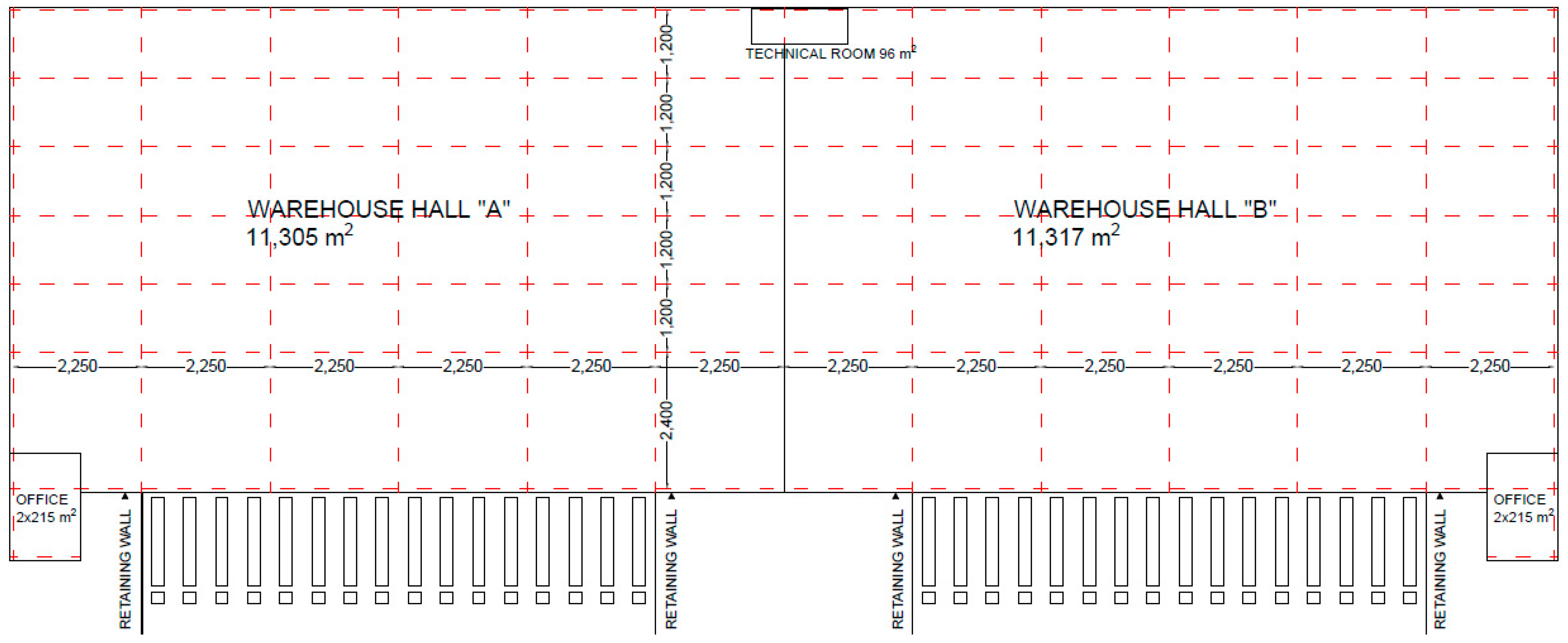
The analysed facility is a combination of a one-story warehouse, contained in the high-bay warehouse section, with a two-story social and office complex. In accordance with the above-mentioned regulations, due to its height of ≈12.5 m, the building is classified as a medium-high (MH). The warehouse and technical part of the building will be intended for the temporary stay of people, while the office part will be used for the permanent stay of people.
Delivery of materials to the facility will be carried out using dock handling systems. Unloading trucks and transporting materials and goods in a part of the warehouse will be carried out using pallet trucks and forklifts. The facility will be a uniform block in the form of a cuboid with protruding social and office blocks (
Figure 1).
The warehouse will be constructed as a single-story building with a technical room for a transformer station and a MV medium voltage and LV low voltage switchgear. The storage height within the hall, calculated from the finished floor to the bottom of the trusses/purlins, will be 10 m, while the height of the building to the upper level of the parapet—approx. 12.5 m., and in the dock 22.5 × 24 m. The hall will be divided into two tenants in accordance with the concept. The roof and façade of the building will be made using light housing; the roof will be illuminated with daylight, constituting 2%, using smoke vents/skylights. Fire resistance of structural elements, roof, and walls will be ensured for a fire load density not exceeding 4000 MJ/m2. To protect the façade from mechanical damage, reinforced concrete walls will be made from −1.20 to +4.20 m high in the dock and entrance gates from the “0” level, while in the remaining part of the building, reinforced concrete foundations will be raised 30 cm above the floor level. The external windows and doors of the building will be made of aluminum, and the delivery zone will consist of system dock gates (32 pcs.) with dimensions of 3 × 3.2 m, and gates with access from the “0” level, with dimensions of 3.5 × 4.2 m. The required temperature in the hall (15 °C) will be provided by heating using radiators or gas heaters. Ventilation in the hall will be implemented using a mechanical exhaust ventilation system with a capacity of 0.25 w/h (19.6 m3/s), and rainwater will be discharged through a vacuum roof drainage system.
The social and office annexes will be two-story turnkey buildings. As in the case of the hall, the roof of the annexes will be made flat and the façade will be made in a lightweight casing in a technology analogous to the warehouse casing. The exterior windows and doors will be made of aluminium, while the interior doors will be veneered with wood. In social and office annexes, electric or gas heating, ventilation, lighting, and water and sewage installations will be provided in accordance with the requirements.
The sustainable building should be designed and constructed in such a way as to meet the fire protection criteria, i.e., load capacity of structural elements, limiting the spread of fire and smoke in the building to ensure efficient evacuation, and limiting the spread of fire to adjacent fire zones or buildings. The basic aspect is the proper classification of the building and dividing it into fire zones depending on the category, which will enable determination of the requirements regarding the fire resistance of individual building elements, the size of fire zones, or the length of fire routes. According to the above, the social and office part belongs to the ZL III category, while the warehouse part to the PM category [
2].
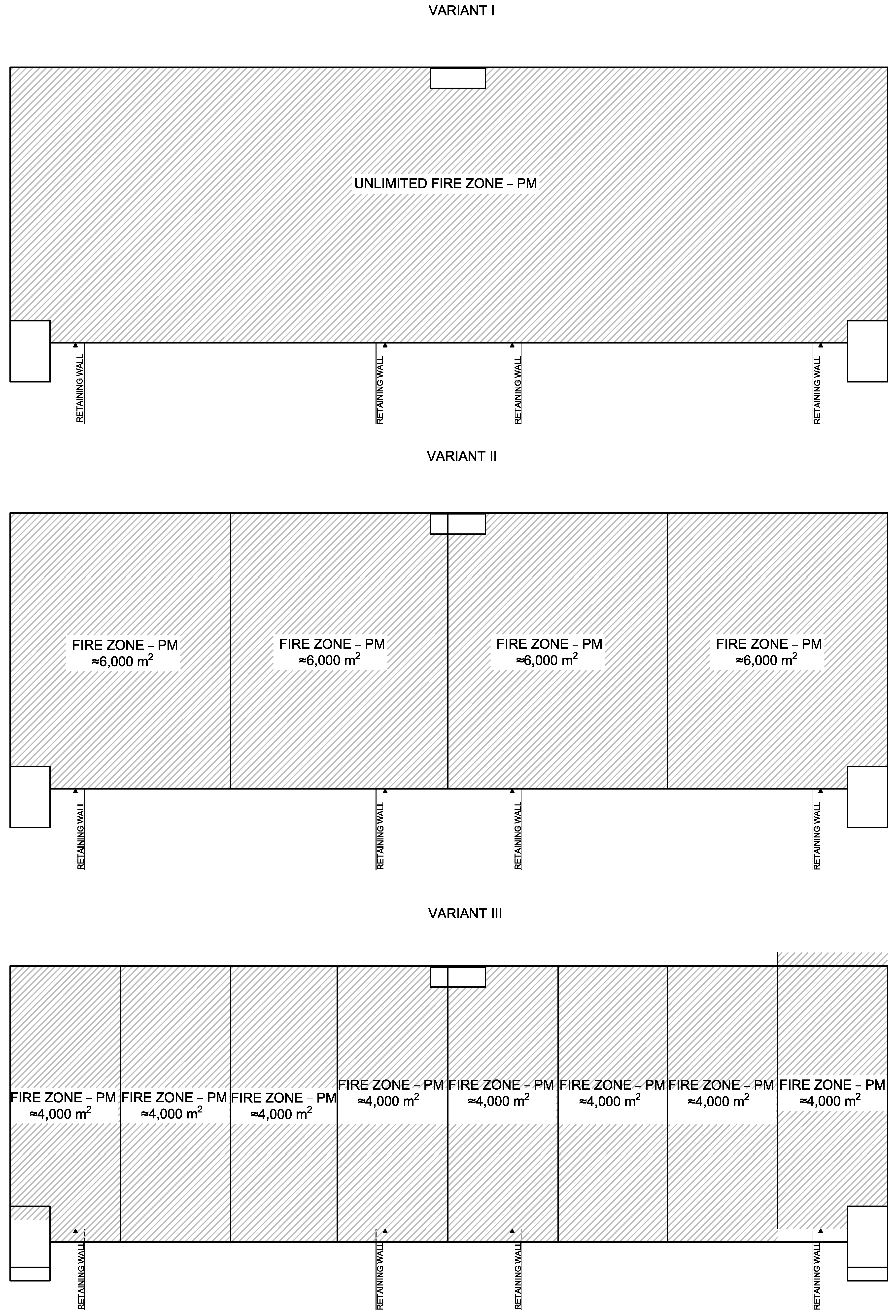
Variants of Construction of a Selected Warehouse Hall with a Social and Office Annexes
Execution of the building structure and wall and roof cladding will depend on its classification and requirements related to fire safety. These requirements enforce several restrictions, which are not always adequate to the budget assumptions or timelines foreseen for the implementation of the investment. However, the impact that required fire safety features have on the sustainability of a building can be reduced with appropriate design strategies. Taking the above into account, the analysis of the construction of the warehouse building should be carried out in the following three variants:
- I.
hall in class “E” of fire resistance, equipped with building elements that do not spread fire and equipped with permanent water extinguishing devices and automatic smoke exhaust devices. The PM zone will constitute one unrestricted fire zone. The scheme for variant I is shown in
Figure 2.
- II.
warehouse hall in class “E” fire resistance, with all building elements that do not spread fire and equipped with automatic smoke exhaust devices. The PM zone will be divided into four fire zones with a maximum area of 6000 m
2. The scheme for variant II is shown in
Figure 2.
- III.
warehouse hall in “B” class of fire resistance. The PM zone will be divided into six fire zones with a maximum area of up to 4000 m
2. The scheme for variant III is shown in
Figure 2.
For the social and office section, in accordance with applicable legal regulations, class “D” of fire resistance was adopted.
3. Cost Estimation of Technological Variants of Hall Construction
In this study, the unit cost method of calculating the cost of technological variants of hall construction by multiplying the quantity of each work item by a unit price was conducted. For this purpose, the Norma Pro Software ver.4.65 (Athenasoft, Poland) was used.
For variant I, the use of permanent water extinguishing devices and an automatic smoke removal system as part of the fire alarm, smoke removal, and sprinkler systems will reduce the fire resistance of the warehouse building from “B” to “E”. The great advantage of such a solution is the possibility of any arrangement of the warehouse since it will constitute one unlimited fire zone. The installation, in accordance with the practice, will be made in the American standard—NFPA 13 Standard for the Installation of Sprinkler Systems. This is a standard that provides the widest scope of application of fixed water extinguishing devices but, at the same time, is the most rigorous in terms of requirements, therefore it is highly appreciated by companies insuring such facilities, where goods of high value are often stored. It is commonly known that fire sprinklers are a significant part of any building’s fire safety system, but they also play a crucial role in sustainable building design. NFPA 13 Standard permits the design of smaller fire safety systems, thereby reducing numbers of sprinklers in each area and eliminating in-rack sprinkler piping. In the event of a fire, fire sprinklers reduce the water waste because they can quickly detect and extinguish the fires using less water than regular systems [
57].
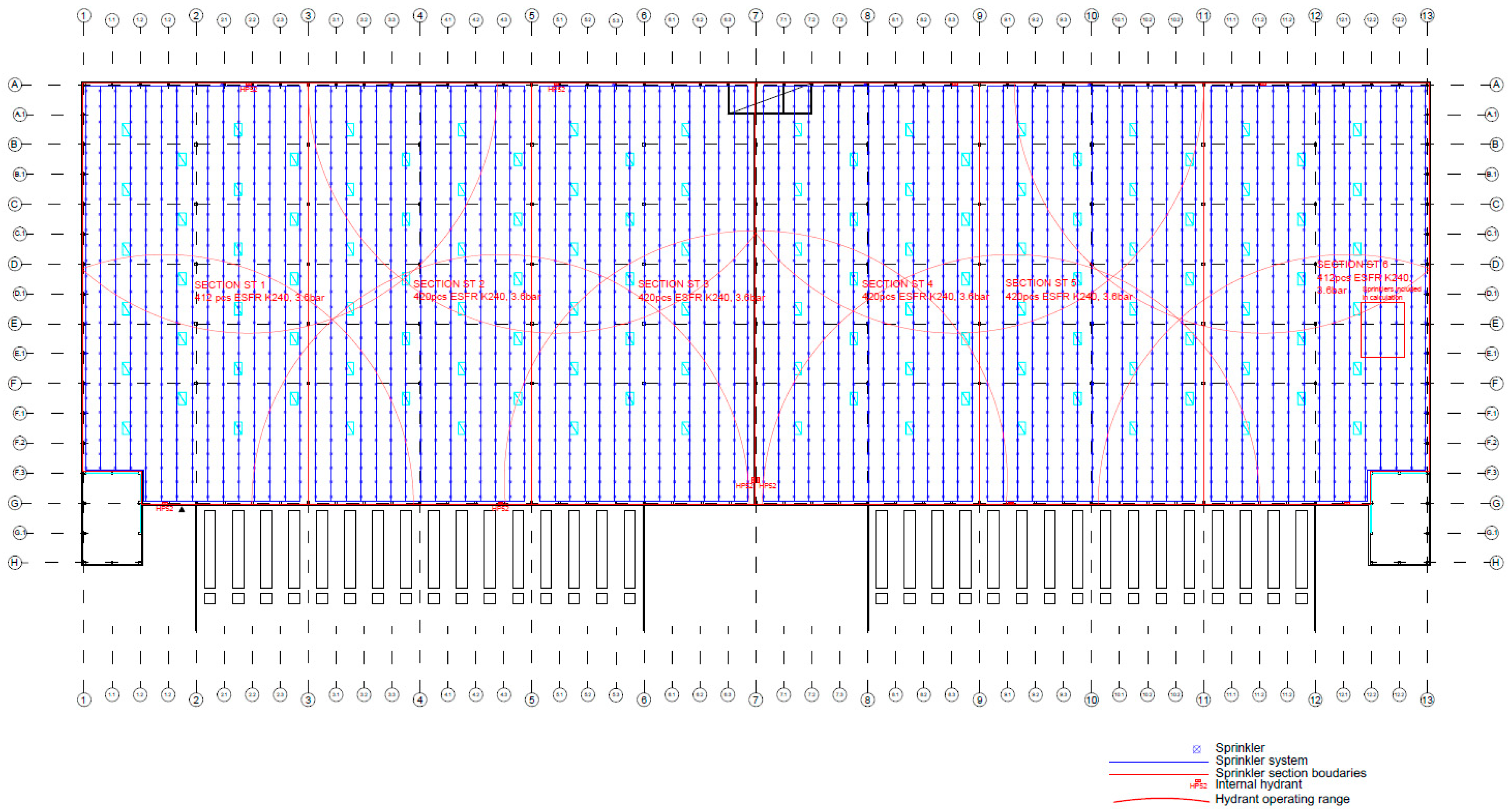
Based on the above guidelines, the hall will be divided into six sprinkler sections (ST1–ST6), of which the largest sprinkler section area will be 3807 m
2. The sprinkler system pipelines, supply manifolds, and locations of control and alarm/valve stations should be drawn on the sprinkler system plan (see
Appendix A). The sprinkler system will be made of black steel pipes, and pipe sections will be connected using grooved connections and threaded couplings. The pipelines will be routed along the numerical axes with a spacing of 2.75 m to 3.1 m, while the sprinkler heads on the pipelines should be spaced at a spacing of 2.8 m to 3.1 m. Such an arrangement will meet the requirements of the standard. To ensure proper fire protection for the entire facility, 2504 pcs of ESFR K240 sprinklers, 3.6 bar, approx. 7600 running meters of water pipes, to which heads will be installed, approx. 440 m of power collectors, and six control and alarm stations will be required. It was assumed that the minimum equipment required for the control and alarm stations would be acquired, which, in accordance with the NFPA13 standard, would consist of a non-return valve and a shut-off valve with electrical or mechanical information about the position. Concerning additional equipment for the valve stations, it is planned to equip them with electronic flow sensors that will be connected to the fire alarm system and will emit a fire alarm in the event of water flow in the sprinkler system. In addition, according to the standard, it is possible to supply internal hydrants from sprinkler system manifolds, provided that the hydrant, located in a given sprinkler section, is supplied with water from the adjacent sprinkler section. Thanks to this solution, there will be no need to build a circumferential internal hydrant system. When two 20 + 20 m hoses are used, 10 internal hydrants will need to be installed in the facility. The sprinkler system can function properly in the facility provided that both the required amount of water and appropriate pressure are provided. The NFPA 13 standard assumes that the water requirement should be calculated for 12 sprinklers. In addition, in accordance with the requirements of the above-mentioned legal regulations, the water requirement for the installation of internal and external hydrants should be added. The water supply network will provide a working pressure of 0.4 MPa, and the water demand for the external hydrant network will be 50 L/s.
Based on the calculations (see
Appendix A), it was assumed that a water reserve tank with a capacity of 724 m
3 should be provided for the needs of fire protection systems. Moreover, to ensure water flow in the sprinkler system and internal hydrants, it will be necessary to build a fire pumping station consisting of two diesel pumps. In the storage section, pipes of the sprinkler system DN80 mm, supply manifolds DN 150 mm, valve station DN 250 mm, and the supply network PP Ø315 (between the pumping station and ST1 section—pressure loss 1 m H
2O/100 m, V = 2 m/s) will be installed.
For the purposes of external firefighting, a perimeter hydrant network of polypropylene pipes should be installed, equipped with 6 DN100 mm hydrants spaced at a maximum of 150 m apart. Due to the water demand (50 L/s), the diameter of the hydrant network Ø250 was selected (pressure loss 0.8 m H2O/100 m, V = 1.5 m/s). As the required reserve of the network constitutes 25% of the entire circuit, it was assumed that this would supply the sprinkler system in the building, which will be connected to the hydrant network.
It will be necessary to install an automatic smoke exhaust system in addition to the sprinkler system. For this purpose, smoke vents with the assumed dimensions of 1.5 × 2.5 m and an active smoke exhaust area of 2.63 m2 in 86 pcs are required. Moreover, there is a need to install 54 roof skylights, which in total will ensure daylighting of the hall at the level of 2%. To reduce the number of smoke vents, a smoke exhaust system was accepted in accordance with the NFPA 204: Standard for Smoke and Heat Venting, which requires that the active surface of smoke exhaust is approximately 1% of the building area. The proposed solution will generate large savings in terms of construction and roofing. In addition, to ensure the air supply for the smoke removal system, dock gates will be used, in which UPS units are additionally installed, to open them in the event of a power failure on the site. To automatically activate the smoke exhaust system, it is recommended to use the POLON 4900 (POLON-ALFA, POLAND) fire alarm system.
Table 1 presents the estimated cost of installation in variant I.
The value of the above works will amount to EUR 759,494.85. The disadvantage of this variant is the high labour intensity of installing the sprinkler system, as well as the long waiting time for fire pumps, which can range from 10 to 12 weeks. The advantage will be that any arrangement of the hall is possible. In addition, fire protection regulations do not account for fire in several buildings at the same time, as in the case of a logistics park consisting of several warehouse facilities, so that the fire tank and pumping station can provide water for several halls. In this case, the additional costs are only related to the implementation of the sprinkler system in subsequent buildings.
In variant II, the purpose of using automatic smoke exhaust devices, as in variant I, will be to reduce the fire resistance class of the building from “B” to “E”, however, in this case it will be necessary to divide the facility into fire zones (see
Appendix A). The scope of works necessary to be carried out (excluding the sprinkler system) to ensure proper fire protection and evacuation conditions differs from the previous variant in several details. First, to ensure automatic operation of the smoke exhaust system, the fire alarm system should be extended with fire and smoke detection sensors. It was assumed that the fire alarm will be calibrated as in variant I in the POLON 4900 system.
The system will work similarly to variant I, with the difference that instead of the flow sensors of the sprinkler system, the signals will be collected from smoke sensors. In the smoke exhaust system, the only difference will be the lack of need to use smoke curtains due to the presence of fire separation walls that will play their role. In the case of internal hydrant installations, an internal water pipe ring should be installed, equipped with two power supplies to ensure the simultaneous consumption of water for fire purposes from four hydrants, amounting to a total of 10 L/s. The hydrant system was assumed to be made of Ø48.3 mm steel pipes, for which the pressure losses will amount to 1.4 bar.
The network supplying the internal hydrants in variant II is proposed to be made of Ø250 PE pipes, in which pressure losses will amount to approx. 0.03 bar over a section of 396.64 running meters. The required discharge pressure in the internal hydrant should be 0.2 MPa. Considering pressure losses, a set of hydrophore pumps should be provided for the installation, which will provide a working pressure of 3.43 bar and a flow of 10 L/s.
Differences in the scope of the external hydrant network in the variants include the use of PE100 SDR13 Ø250 pipes in variant II on all sections, including a 25% reserve of the circumference, which will be used to supply the internal hydrants installation. For the installation of internal and external hydrants, two diesel fire pumps (primary and reserve) with a minimum capacity of 50 L/s and working pressure of 3.43 bar should be installed.
Due to the lack of a sprinkler system in the variant, the required amount of water for external hydrants compared to variant I will double, making the capacity of the tank slightly larger (min. 756 m
3). For this purpose, a typical tank with a height of 12.12 m, a width of 9.17 m, and a capacity of 768 m
3 was assumed.
Table 2 shows the approximate cost of making individual elements of the fire installation and smoke exhaust systems for variant II.
The cost of the above fire protection and signalling installations will amount to EUR 415,240.60. Compared to variant I, savings of EUR 344,254.25 will be generated. The execution time of the fire alarm system should also be shorter than that of the sprinkler system, due to a lower labour consumption.
In variant III, the building will be made in class “B” of fire resistance. The building will be provided with basic fire protection in the form of internal and external hydrants. The fire alarm system will be limited to manual activation only by using manual call points. After their use, an audible signal will be activated in the facility, the gas supply will be shut off, and the ventilation system will be disabled.
The cost of the fire alarm system will be the same as for variant I. However, significant differences will appear in terms of daylight illumination. Smoke vents will be replaced by 138 roof skylights, but it will be required that they have a roof fire resistance class of EI 30. In the remaining elements (hydrant installation, water supply tank, or pumping station), there will be no differences compared to variant II.
Table 3 shows the approximate costs that must be incurred in order to perform individual elements of the building in variant III.
The total cost of the above works will be EUR 342,289.48; in the context of building improvements, it will be the most advantageous both in terms of money and time.
4. Variant Analysis of the Operation of the Fire Protection System
As part of the simulations carried out in the PyroSim (2022) program, it was assumed that the source of the fire is a rectangular model object in the form of a fire simulator with dimensions of 1 × 1 × 0.5 m [width × length × height] located in one of the corners of the hall. The upper base of the cuboid was assumed as the combustible surface. Flaming of the combustible surface begins at the start of the simulation. The following parameters of the combustible surface were adopted:
burnt material: oak wood,
combustible surface temperature: 5000 °C,
fire load curve parameter (HRR): 500 kW/m2.
The numerical model presents the possibility of controlling the opening of smoke dampers. To illustrate the possibilities, the opening of the smoke dampers in the tenth second of the simulation was assumed for each calculation variant.
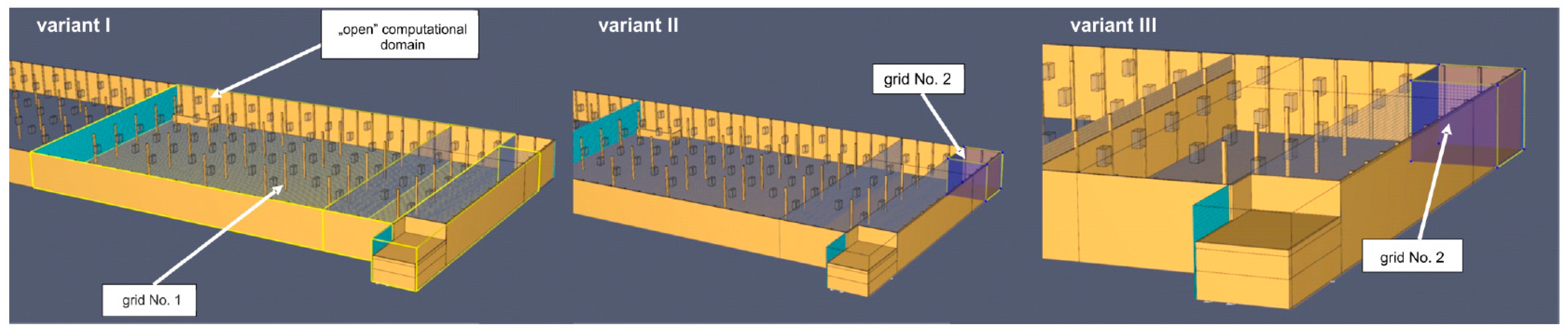
4.1. Computational Grids
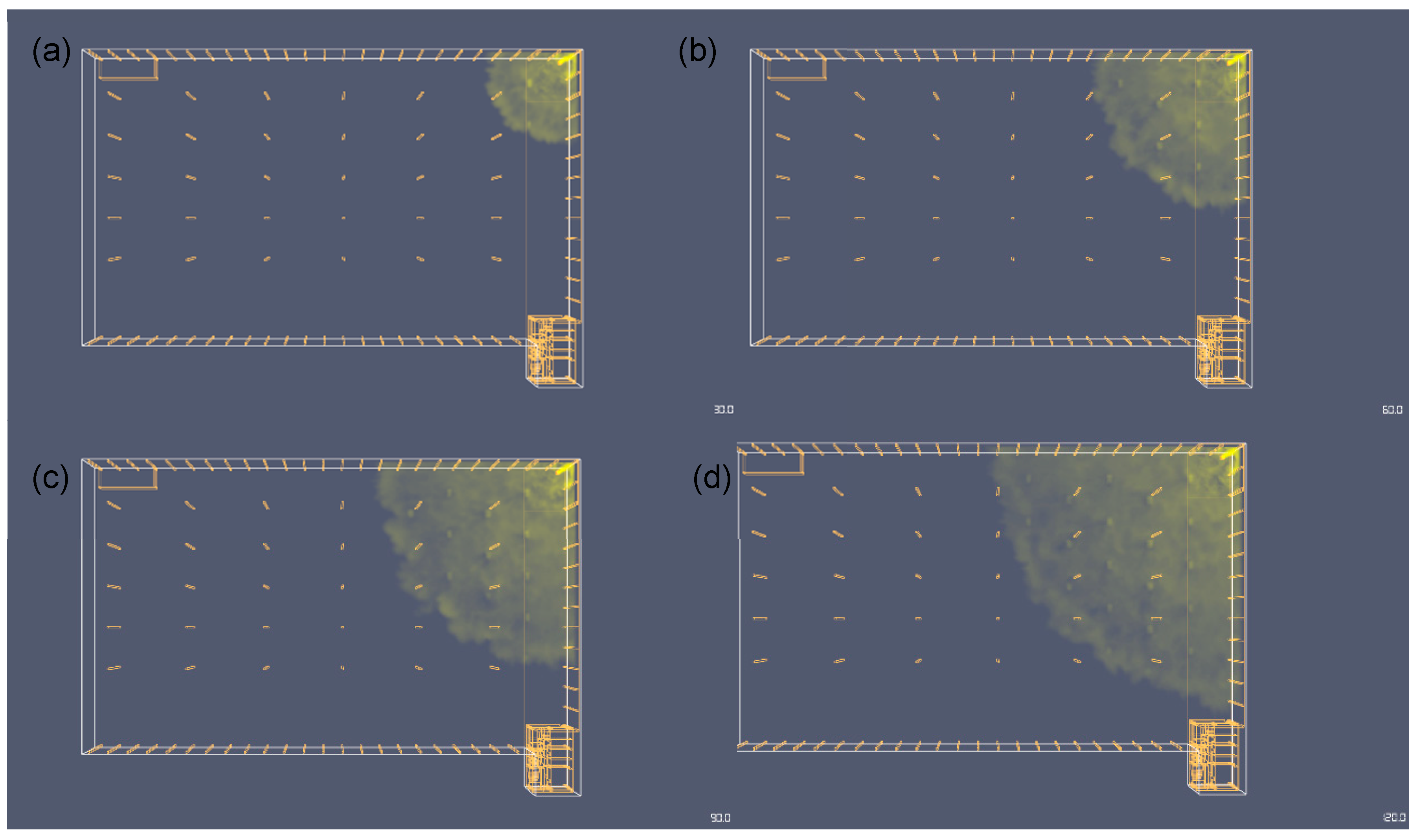
As part of the numerical simulations, three fire variants were analysed: I—the entire hall is one fire zone, II—the hall is divided into four fire zones, III—the hall is divided into six fire zones. Parameters of computational grids for all analysed variants are presented in
Table 4.
The possibility of changing the network parameters for the third calculation variant (mesh density) resulted from the analysis for a relatively small fire zone in terms of volume compared to the zones analysed in variants I and II. Thus, in variant III, it was possible to present reliable quantitative results regarding the course of temperature values at a selected point of the computational domain and in the selected result plane. In addition, it was also possible to present the distribution of isothermal surfaces for two temperature values.
In each variant, the same simulation time (120 s) was adopted. The result was estimated based on the results of the evacuation model (increasing the resulting value of the available evacuation time almost twice) from the hall developed in the Pathfinder program (the result of the simulation of the evacuation time of 100 people from the warehouse is 65 s).
Conducting preliminary simulation tests, the results of which are not included in this study, made it possible to determine the maximum volume covered by smoke in the final phase of the simulation in Variant I. The results of the pilot tests made it possible to determine the area requiring coverage using a computional grid. Covering the entire model with a grid would be “uneconomic” from the point of view of computational expenditure and pointless from the point of view of the lack of significant phenomena occurring outside the area designated in the pilot studies. As a result of the analysis, the volume of the hall, corresponding to approximately 50% of its length, was covered with a computational grid. In the immediate vicinity of the fire source, the calculation grid was locally compacted (
Figure 3).
Figure 3 shows the computation grids for all variants.
In variant II, the impact of fire zones on the spread of smoke was examined. The hall was divided into four fire zones. The spread of smoke in the extreme zone in which the fire simulator was located was investigated. The use of a partition made it possible to reduce the number of elements of the computational grid. In the immediate vicinity of the fire source, the calculation grid was locally compacted (
Figure 3).
In variant III (
Figure 3), as in variant II, the influence of the fire zone on the spread of smoke was examined. The hall was divided into six fire zones. Similarly to the second variant, the spread of smoke was analysed in the extreme zone. The use of a partition made it possible to reduce the number of finite elements. In the immediate vicinity of the fire source, the calculation grid was locally compacted (
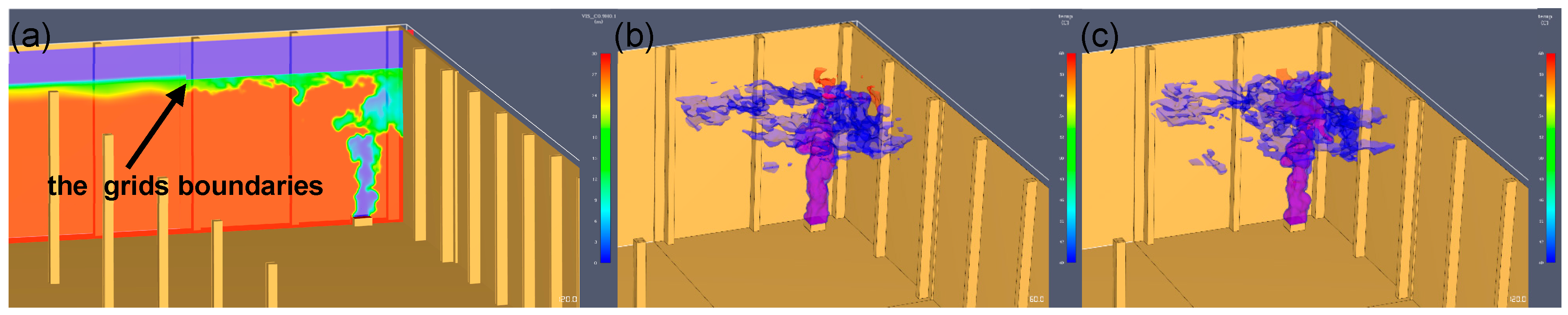
Figure 3—grid no. 2). This density is greater than in the previous variants (in this case, each mesh element is a cube with an edge length of 10 cm; in the previous variants the length of the mesh cube edge was 25 cm). The denser mesh made it possible to obtain additional characteristics, such as temperature changes at an arbitrarily selected point above the fire source. To present other functionalities of the program, an additional parameter in the form of visibility was determined using an additional result plane for this purpose.
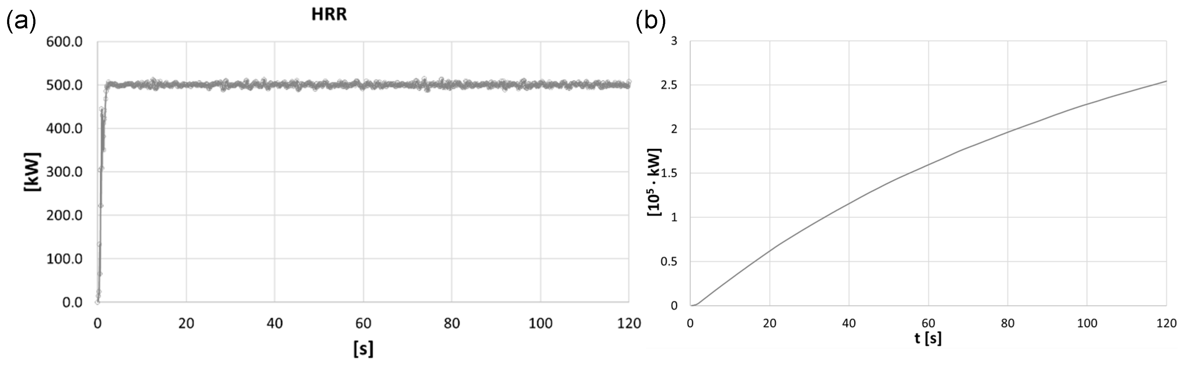
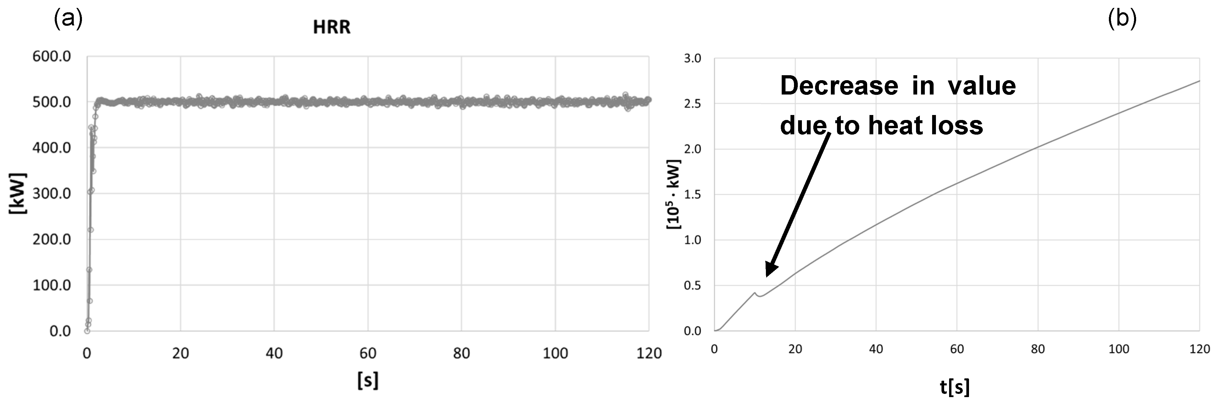
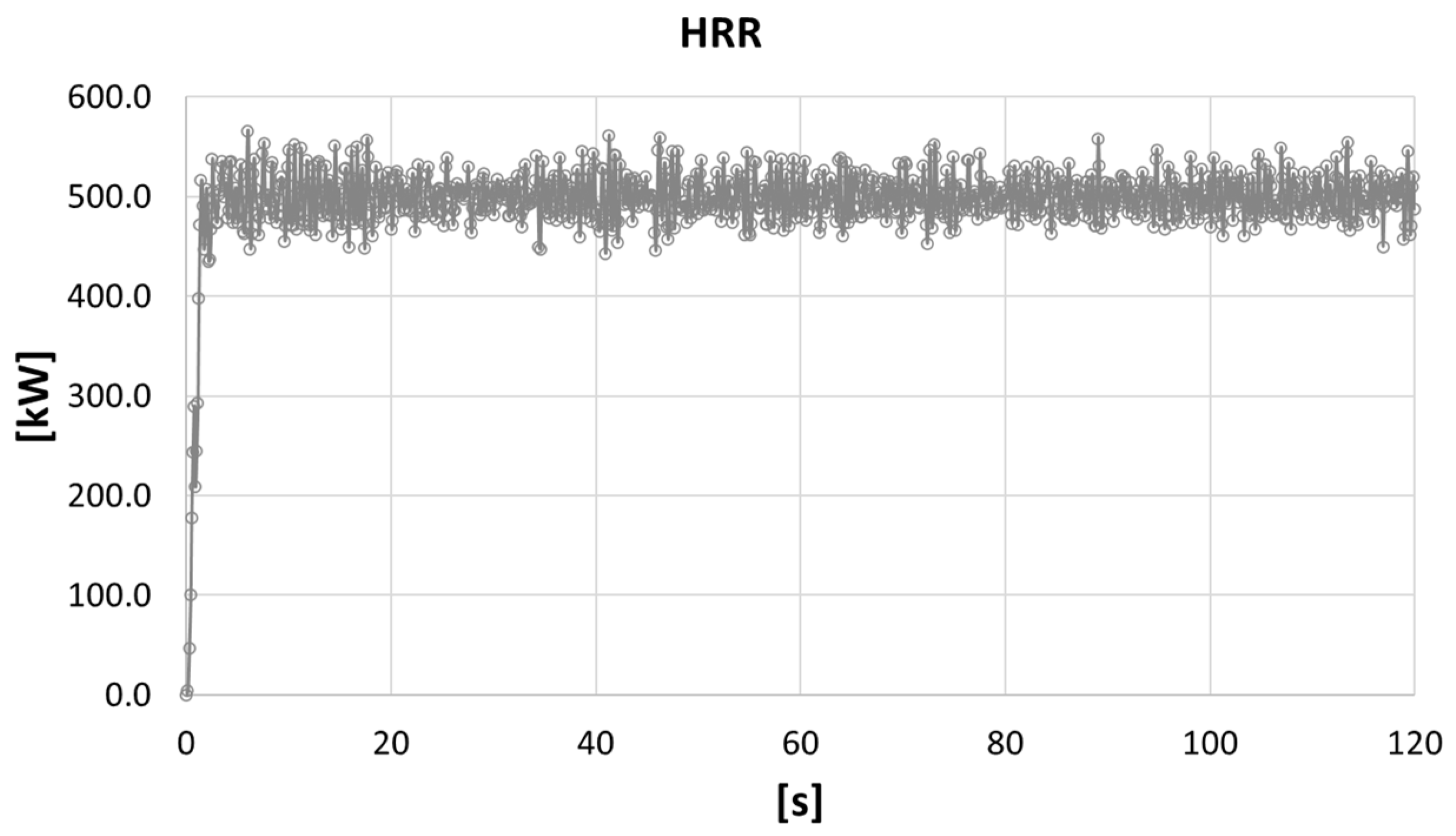
Figure 4 shows the course of the HRR characteristic and the total heat flux in the first calculation variant. The HRR value after the transitional period related to the ignition of the combustible surface stabilizes at the level of 500 kW (set HRR value per one square meter of the combustible surface). The course of the total heat flux is presented with a curve increasing to the value of approx. 200 kW for 120 s of the simulation.
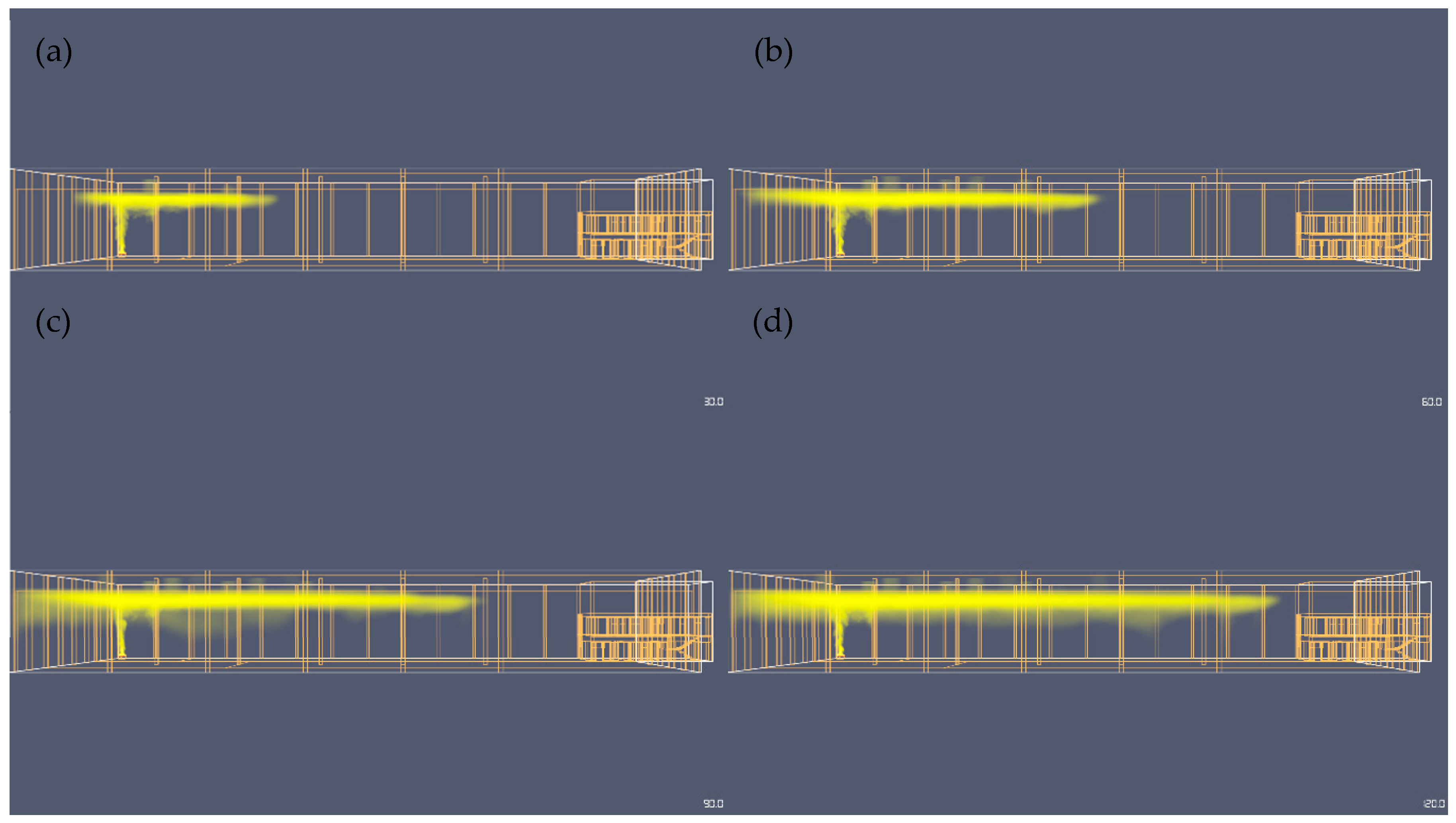
4.2. Smoke Distribution
Figure 5 shows the distribution of smoke in the computational domain for variant I in the top view and in the side view. In each of the variants, to improve the contrast, the smoke is marked in yellow.
Figure 6 shows the course of the HRR characteristics and the total heat flux in variant II.
In the case of the HRR course, the value of the analysed parameter, similar to variant I, oscillates around 500 kW. A qualitative change in relation to variant I was observed for the course of the value of the total heat flux as a function of time. The analysis of this course revealed the moment of opening the smoke dampers. The activation of the flaps resulted in a heat sink. This decrease over the course of the total heat flux is represented by a visible decrease in value. This decrease is not visible in variant I due to the small “saturation” of the large-volume computational domain of large cubic capacity, with heat.
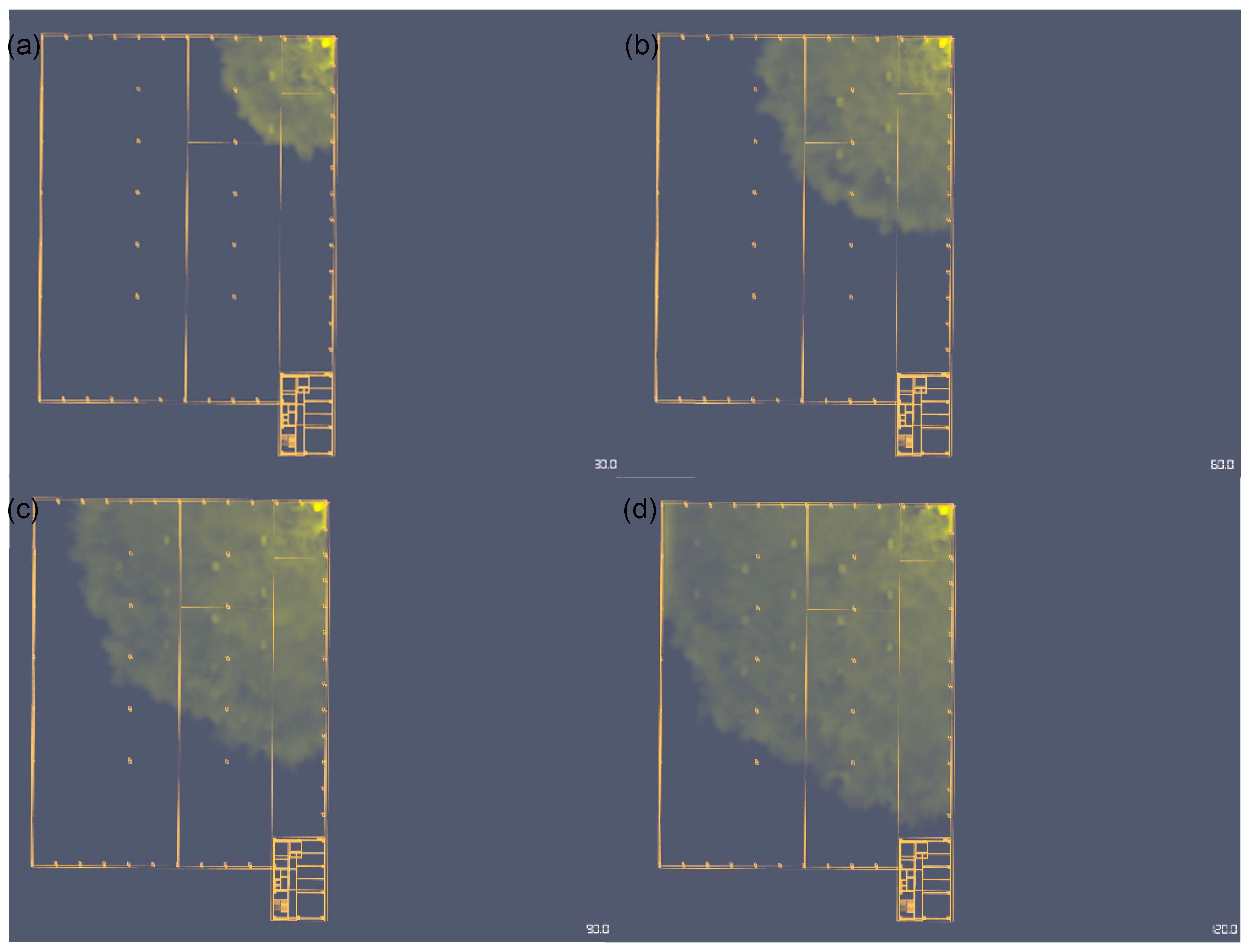
Figure 7 shows the distribution of smoke in the computational domain for variant II in the top view and side view.
Then, the model for variant III was produced. The analysis of the courses of supervised fire characteristics showed a qualitative change only in the case of the HRR course, which is presented in
Figure 8. The greater dispersion of instantaneous values around the average value is related to the density of the computational grid, and thus to a more accurate representation of the instability of the flame on the combustible surface of the fire simulator.
Figure 9 shows the distribution of smoke in the computational domain for variant III in the side view.
In
Figure 10, the result plane x–z shows the visibility in 120th second for variant III and the distribution of isothermal surfaces for two temperature values: 40 °C and 60 °C.
With regard to the above results of visibility and isosurface course, it is concluded that after 120 s of the simulation for variant III, the smoke in the vicinity of the fire source does not limit visibility due to its concentration in the ceiling area. The distribution of isothermal surfaces for variant III shows that after 120 s of simulation, the temperature posing a threat to humans is reached only in the immediate vicinity of the fire source.
5. Discussion
The analysis shows that in terms of fire regulations, there are several possibilities to implement the analysed investment in the context of costs. Fire protection requirements have a large impact on building structure solutions, roofing, and façade systems. Parameters such as the area and height of the facility impose numerous limitations in the selection of solutions and the need to use additional systems and security measures. The analysed legal requirements allow for three different variants of the investment implementation, in terms of fire protection requirements.
In the analysis, variants I and II assumed a reduction of the fire resistance class of the selected facility from “B” to “E”, while variant III included the implementation of the investment in the “B” fire resistance class. The breakdown of the fire protection system costs for the three variants of the hall construction was as follows: I—EUR 759,494.85, II—EUR 415,240.60, and III—EUR 342,289.48. For the three variants, the costs were at the same level for the installation of internal (EUR 3170.13) and external hydrants (EUR 9632.60), the container pumping station building (EUR 32,612.95), and the foundation for the water storage tank (EUR 43,483.93). For variants II and III, identical costs were observed for the internal hydrant installation ring (EUR 20,862.72), fire pumps (EUR 36,961.34), and the Ø250 hydrant network (EUR 87,891.38). The cheapest variant was the option of building a hall in the “B” class of fire resistance, the cost of the necessary installations being EUR 41,7205.37 lower than variant I and EUR 72,951.12 lower than variant II. The latter, compared to variant I, generated savings of EUR 344,254.25.
Considering the possibility of arranging the warehouse space, variant I, despite the high costs of implementing the fire protection system, will be the most flexible in this respect. Since it will constitute one unrestricted fire zone, it will be the only one out of the three analysed variants that will enable the construction of the structure without the need to use additional divisions of the structure with fire separation partitions.
In addition to the sustainable hall design, several numerical simulations were performed in which the basic analysed parameter was the spread of smoke in the computational domain. The analysis of the results obtained for each calculation variant confirmed the maximum accumulation of smoke in the ceiling zone. In terms of quantity, it was found that the thickness of the soffit layer decreases with the increase in the number of fire zones, which is a natural consequence of the physical limitation of smoke propagation along the length of the hall. However, the greatest thickness of the ceiling smoke layer, characteristic for the third calculation variant, is incomparably smaller than the total height of the hall (from the floor to the ceiling) and therefore does not pose a threat from the point of view of limiting visibility during evacuation in the time range from 0 to 120 s. Quantitative confirmation of the above observation is revealed by the visibility results presented on the resulting plane stretched along the length of the fire zone—in which the fire simulator was located—passing through its center and parallel to the front wall of the hall. The obtained results indicate a significant limitation of visibility from 12 to 0 m only in the volume above the combustible surface and in selected points of the corner of the hall created at the junction of its side and rear walls. The obtained results also allowed us to exclude the risk of a heat impulse up to 120 s after the occurrence of a fire in the fire simulator, which quantitatively directly justifies the numerically determined distribution of arbitrarily selected 40 °C and 60 °C isosurfaces. In addition, the results of the simulations made it possible to determine the total heat flux at a given time in the computational domain, the value of which was between 250 kW and 300 kW.
Choosing the best variant for the selected investment requires a list of technological solutions and the costs of all necessary installations and works. In connection with the above, the next analysis will concern the costs of earthworks, construction solutions, and industry installations required for the proper design and operation of the warehouse hall with social facilities. In addition, the fire simulation results will be supplemented by determining the most optimal escape routes from the building in terms of safety and length.
6. Summary and Conclusions
The analysis of technological variants of the construction of a warehouse hall with a social annex in the light of fire regulations showed vast differences in the costs of the selected investment. In financial terms, the best solution is to implement a fire protection system for variant III, i.e., a building in class “B” of fire resistance. Unfortunately, in this variant, the PM zone must be divided into six fire zones with a maximum area of up to 4000 m
2, which may not be an advantage from the investor’s point of view due to limitations in the arrangement of space for logistics and storage needs. In terms of fire protection and evacuation conditions, despite the highest costs of fire protection installation, variant I is the most advantageous. The biggest advantage of this solution is the possibility of building a hall of any surface area, as well as the fact that the larger the area, the more cost-effective it is to use a sprinkler system and smoke exhaust system. From the user’s point of view, the use of a sprinkler system and smoke removal is a more practical solution, because the sprinkler system is not a bypass for legal requirements to reduce building construction costs, but an effective tool for extinguishing a fire. According to statistics, 8 out of 10 fires are extinguished after the automatic activation of a maximum of four sprinklers, so it can be said that the effectiveness of the system is very high [
58,
59]. The investment in a sprinkler system pays off quite quickly in the cost of building insurance, as it is a solution very much preferred by insurance funds, which prefer to pay damages for damaged property within the sprinkler operation area, rather than for the entire facility and the property accumulated in it. According to Issman and Nisja’s [
60,
61] study, which compared insurance savings for buildings with and without sprinkler systems, the reductions in insurance rates for sprinklered buildings are significant and often enough to justify the cost of the sprinkler system. Moreover, installing a sprinkler system could save on insurance premiums per year, and the cost of the installation will be paid back in just four years.
On the other hand, variant II is an intermediate option between the other variants. It offers more possibilities in arranging warehouse space than variant III (four PM zones with an area of 6000 m2 each), but, due to the use of automatic smoke exhaust devices, it generates higher fire protection installation costs (by over EUR 70,000) compared to variant I.
The use of the commercial PyroSim computing package allowed for several model fire simulations. The basic criterion for assessing the quality of the design of the warehouse hall in the conducted research was the effective spread of smoke. However, the capabilities of the program allow us to extend the spectrum of monitored parameters, such as the course of temperature changes. As a result of the calculations, a set of quantitative and qualitative data was obtained that can be used to assess the hall design in terms of fire safety and conducting effective evacuation not only for the case of model ignition of a fire simulator, but also for other fire variants.
Based on the analysis carried out as part of this work, the following conclusions can be drawn:
the time and cost of the investment are significantly influenced by the conditions of fire protection and evacuation;
lowering the fire resistance class of the building with the simultaneous use of automatic smoke exhaust devices and fixed water fire extinguishing devices can immensely reduce the cost of insurance of the facility, but not the cost of the investment;
the use of a sprinkler system and a smoke exhaust system is economically justified in the case of logistics parks or warehouse facilities with areas exceeding 20,000 m2,
lack of automatic installations and the division of the warehouse into six PM zones reduces installation costs massively;
a number of numerical simulations for each calculation variant confirmed the maximum accumulation of smoke in the ceiling zone;
the thickness of the ceiling layer decreases with the increase in the number of fire zones, which is a natural consequence of the physical limitation of smoke propagation along the length of the hall;
the greatest thickness of the ceiling smoke layer was obtained for the third calculation variant, the value of which was incomparably lower than the total height of the hall and did not pose a threat from the point of view of limiting visibility during evacuation (0 to 120 s);
visibility results presented on the result plane stretched along the length of the fire zone indicated a big reduction in visibility from 0 to 12 m only in the volume above the combustible surface and in selected points of the corner of the hall and allowed to exclude the risk of a heat impulse up to 120 s after the fire in the fire simulator;
the value of the total heat flux at a given time in the calculation domain, based on the results of the simulations, was determined in the range of 250 kW and 300 kW.

 ,
, 


