Article

Study on the Biofilm Kinetics in Micro-Electrolysis Biological Reactors

1
Engineering Research Center of Coal-Based Ecological Carbon Sequestration Technology of the Ministry of Education, Key Laboratory of Graphene Forestry Application of National Forest and Grass Administration, Shanxi Datong University, Datong 037009, China
2
Datong Ecological Environment Monitoring Center, Datong 030027, China
3
Xinjiang Institute of Ecology and Geography, Chinese Academy of Sciences, Urumqi 830011, China
4
College of Resources and Environment, University of Chinese Academy of Sciences, Beijing 100049, China
*
Authors to whom correspondence should be addressed.
Sustainability 2025, 17(3), 1105; https://doi.org/10.3390/su17031105
Submission received: 15 December 2024 / Revised: 20 January 2025 / Accepted: 27 January 2025 / Published: 29 January 2025
(This article belongs to the Section Sustainable Water Management)

Abstract

:
The kinetic study of micro-electrolysis biotechnology not only determines the removal efficiency of a micro-electrolysis process but also influences the optimal design of a system. This paper investigates the relationship between electric field strength, pollutant degradation rate, and biofilm thickness by constructing a microporous biofilm model for pollutant removal. Additionally, the study derives equations linking electric field strength to reaction rate, pollutant effluent concentration, and biofilm thickness under both high and low pollutant influent concentrations. This work bridges the gap between macroscopic processes and periplasmic mechanisms, enhancing our understanding of pollutant removal mechanisms and facilitating process optimization. It also provides theoretical support for the sustainable development of micro-electrolysis biotechnology. Future research will focus on experimental validation and the optimization of model accuracy and flexibility to accommodate diverse treatment conditions.

1. Introduction

In the context of global water stress and increasing environmental pollution, the sustainability of wastewater treatment technologies has received increasing attention. Traditional wastewater treatment technologies have low treatment efficiency [1], such as the chemical precipitation method, which requires the use of a large number of chemicals in the wastewater treatment process and the removal of pollutants by precipitation, which may lead to secondary pollution problems [2] and bring additional pressure on the environment. In order to solve these problems, micro-electrolysis biofilm technology, as an emerging means of wastewater treatment, is gradually gaining widespread attention. This technology has significant sustainability and environmental advantages by enhancing the biochemistry of industrial wastewater and effectively removing organic matter, heavy metals, and microbial pollution [3]. A micro-electrolysis-biological treatment integrates the electrochemical reaction of iron-carbon micro-electrolysis with biological processes such as activated sludge or biofilm reactors [4,5]. Micro-electrolysis technology mainly involves the reaction between electrodes (typically made of iron or carbon-based materials) and ions in water, generating reactive species with strong oxidative capabilities, such as hydroxyl radicals (OH) and ferrous ions (Fe²⁺) [6]. These reactive species undergo reduction and oxidation reactions that facilitate the decomposition of complex organic pollutants and the removal of heavy metals. Additionally, they produce other essential compounds that create favorable conditions for microbial growth, thereby enhancing the performance of bioreactors in water treatment [7]. Current research on micro-electrolysis-biotechnology treatments has mainly focused on the removal of pollutants (e.g., dichromate index CODcr, ammonia NH₃-N, total phosphorus TP, heavy metals, antibiotics, endocrine disruptors, and emerging pollutants such as PPCPs) [4,8,9,10,11,12], the systematic optimization of reaction parameters (including hydraulic retention time) [13], and bioreactors [14,15], electrode material improvement [16], the exploration of synergistic mechanisms (e.g., pollutant degradation mechanisms and biofilm kinetic modeling) [17,18], and energy-saving efficiency improvements [19].
The degradation principles of sewage and wastewater treatment by applying an electric field to a bioreactor and utilizing the electrochemical effect, the degradation effect of organisms, and the coupling effect of the two are relatively complex. It has been shown that in the case of an applied electric field, the permeability of a cell membrane is improved due to the stimulating effect of an electric current, and nutrients can migrate directionally through a cell membrane and be utilized by microbial cells, which improves the mass transfer effect of a substrate [20]. Weak electric and magnetic fields are prevalent in all microorganisms, and the application of micro-electric fields and appropriate current densities to an organism can play a regulatory role, and an applied electric field can stimulate and strengthen the enzyme system of a microorganism and improve the processing capacity of a bioreactor [21]. With a gradual increase in electric field intensity, the strength factor of a biofilm becomes larger [22], but when an applied electric field is too strong, it can lead to microbial metabolic disorders or even cause microbial cell death [23] and destroy a biofilm. Therefore, obtaining the appropriate current intensity is the key to the performance of micro-electrolysis biotechnology.
Kinetic studies of micro-electrolysis biotechnology have focused on the electrochemical reaction rate, the reaction mechanism, and their effect on pollutant removal efficiency in water. It was found that the reaction rate constant during micro-electrolysis is affected by several factors, including current intensity, electrode material, pollutant concentration, and pH [24]. A reaction rate usually accelerates with increasing current intensity, but it begins to level off when the pollutant concentration reaches a certain level, and it peaks and then declines. [25] An excessive current may lead to the excessive corrosion of electrodes, which affects the stability and efficiency of a reaction. To better understand the reaction kinetics of the micro-electrolysis process, researchers have proposed a variety of kinetic models. The commonly used models include the primary reaction kinetics model [25], the secondary reaction kinetics model [26], the Monode kinetics model [27], and the Langmuir–Hinshelwood model [26]. These models can help researchers to predict reaction rate and pollutant removal efficiency under different experimental conditions. Although the application of micro-electrolysis biotechnology in the field of water treatment has made some progress, there are still some challenges in the kinetic research, and the technical principles are still in the exploratory stage. First, the multiphase reaction and complex electrochemical mechanism of the micro-electrolysis process make the kinetic modeling process more complicated and require more experimental data and theoretical analyses for validation. Second, it has been shown [25] that the formation of a biofilm on an electrode plays a crucial role in the efficiency of the electrochemical bioprocessing system, but the interaction mechanism between the current intensity and the microorganisms has not been elucidated.
This paper introduces, for the first time, a method for pollutant removal by constructing a microporous biofilm model in a micro-electrolysis bioreactor. The study analyzes the calculation methods for the surface diffusion coefficient (D) and molar flux (J) of the biofilm under the influence of an electric field, and the relationship between the electric field strength and the pollutant reaction rate and the thickness of the biofilm of the bioreactor under the action of the applied electric field force is deduced. Subsequently, the relationships between the electric field strength and reaction rate, effluent pollutant concentration, and biofilm thickness in water treatment systems with different pollutant concentrations are discussed, and the equations for reaction rate and electric field strength are simplified. The equations established in this paper, which are based on theoretical calculations, link the two reaction processes in the micro-electrolysis biological system, enabling us to further understand the reaction rates, reaction pathways, and degradation mechanisms of pollutants in the micro-electrolysis treatment process, and then they optimize the reactor design and operating conditions. This can help to improve the treatment capacity and energy efficiency of a reactor and minimize the waste of resources and the generation of secondary pollution, thus promoting the development of wastewater treatment technology in the direction of more environmentally friendly, energy-saving, and low-carbon methods.

2. Hypothesis of Biofilm Formation

Biofilm formation is assumed to occur when water flows over the surface of a carrier, transporting microorganisms to the surface where they bind through an immobilization process. A biofilm’s growth is maintained through the adsorption, transfer, diffusion, and oxidative degradation of organic nutrients in water [28]. Studies have shown that a biofilm is a mucous membrane covered with microorganisms hanging on solid surfaces, with filamentous bacteria entangled and spread in the water. Mature microbial membranes have three-dimensional structures, and a dynamic equilibrium is formed between the shedding of aging biofilms and the generation of new biofilms [29]. Biofilm reactors can be classified into planar biofilms and spherical biofilms based on the shapes and sizes of the solids attached to the biofilms. Solid surfaces that are considered flat include biological rotating discs, honeycomb packing filters, and block-packing drip filters, while biological fluidized beds, expanded beds, etc. are considered spherical and have biofilms attached to solid particles, with a particle size of less than 1 mm [30]. This study focuses on a planar biofilm as the primary research subject. Flat electrodes are arranged within a bioreactor to apply a stabilized DC voltage.
The water flows along the surface of the biofilm, the interfacial substrate concentration is CB, and the substrate diffuses into the biofilm and performs biochemical reactions within the membrane, which are driven by a lateral concentration gradient. The following assumptions are made to model the biodegradation of organic matter in the construction of an enhanced bioreactor:
(1)
The flow rate of the subject solution along the biofilm surface is high, and the liquid-film diffusion resistance is negligible.
(2)
The biofilm is a homogeneous membrane, and the membrane density remains constant.
(3)
The pollutants in the effluent are homogeneous, i.e., the ions have a uniform radius.
(4)
In the biofilm, the viscosity coefficient of the gelatinous viscous material produced by the microorganisms is a constant value.
(5)
The applied electric field is uniform.
(6)
The electrostatic force between ions is neglected.
(7)
The amount of electricity charged by the pollutants is the same.
The above series of assumptions simplify the micro-electrolysis planar biofilm model established under the action of the electric field, which is conducive to analyzing the diffusion of pollutants in the biofilm microcells and exploring the issue of the influence of electric field strength on the diffusion of pollutant substrates in micro-electrolysis bioreactors.

3. Biofilm Kinetics Under the Action of an Electric Field

3.1. Determination of the Diffusion Coefficient D Under the Influence of an Electric Field

Before applying the electric field to the pollutant, two forces are acting on it: the molecular thermodynamic force and the frictional resistance of the viscous substance. Afterward, an electric field force is introduced, in addition to the two equilibrium forces, ultimately resulting in a three-force equilibrium. This equilibrium involves the molecular thermodynamic force, the frictional resistance of the viscous substance acting on the pollutant, and the electric field force on the pollutant. This leads to Equation (1), as follows:
Fr + Fd = f,
where Fr represents the molecular thermodynamic force (10−6 N), Fd is the electric field force (10−6 N), and f is the frictional resistance (10−6 N).
According to Stoke’s law [31,32], the frictional resistance of the spherical particles moving through the solution is given by the following equation (Equation (2)):
f = 6πrηv,
where 6π is a constant, r is the radius of the spherical particle (cm), η is the viscosity coefficient of the solution (g/(cm·s)), and v is the velocity of motion (cm/s).
Under the action of the electric field, the velocity of motion v of the spherical particles moving in the solution is composed of two forces moving in two directions, respectively, where the velocity vd caused by the electric field force and the velocity vr caused by the molecular thermodynamic force. It is assumed that two such corresponding friction forces can be divided into fd as and fr. Therefore, Equation (1) can be simplified as follows:
Fr + Fd = fd + fr,
and since Fr = fr, this simplifies to the following:
Fd = fd
and
Fd = qE,
where E represents the field strength (v/m) and q is the electric charge (coulomb C).
Therefore, the relationship between q, E, and the sum of the other terms is expressed as follows:
qE = 6πrηvd.
When there is no electric field force and there is a two-force equilibrium, the two equilibrium forces are the molecular thermodynamic force of the pollutant and the frictional resistance of the viscous material to the pollutant, and therefore, Fr = fr. When an electric field force is added, that is, there is a three-force equilibrium state of the molecular thermodynamic force of the pollutant, there is a frictional resistance of the viscous material to the pollutant, as well as the electric field force on the pollutant, and so we can obtain Fd = fd, and from this, we can obtain Equation (3). After that, the electric field force Fd = qE can be derived from the electric field force [33] under the action of the frictional resistance of the spherical particles moving in the solution, as follows:
v d = q E 6 π r η .
Figure 1 shows a schematic diagram of the diffusion of pollutants within a biofilm. The length of the mean free range λ (the distance that any molecule can cross before colliding with any other molecule) on both sides of the KK′ plane defines the two planes II′ and HH′, yielding the two regions S and T. Therefore, λ/v is the time required to cross λ. The cross-sectional area of the microbial membrane is P, and the volume of the membrane is . The molecular density at the KK′ plane is nA molecules/cm3, and the concentration gradient is d n A d l ; therefore, the average concentrations can be expressed as n A λ 2 d n A d l   and n A + λ 2 d n A d l , respectively.
J is the molar flux, a is the ratio of the number of molecules passing through the KK′ surface to the total number of molecules, and L is the Avogadro constant. The relationship between these quantities is expressed by the following equation:
J L P λ v = a P λ n A λ 2 d n A d l a P λ n A + λ 2 d n A d l .
From this, we derive the following:
J = a λ v L d n A d l = a λ v d c d l .
Comparing the above with the equation from Fick’s first law:
J = D C l ,
we obtain:
D = a v λ ,
where D represents the diffusion coefficient. Substituting v = v d + v r into this equation, we obtain the following:
D = a λ v r + a λ v d = D r + D d = D r + a λ q E 6 π r η ,
where Dr represents diffusion coefficients due to molecular thermodynamics and Dd represents diffusion coefficients due to electric field forces.
The molar flux J is the magnitude of the molecular mobility of a substance, which can be expressed as a flux, and it refers to the number of moles or milliliters of the substance per square centimeter per second passing through the imaginary plane, and the larger the concentration gradient, the greater the diffusive flux. The diffusion coefficient D is an important physical quantity that describes the rate of diffusion. It is equivalent to the diffusion flux when the concentration gradient is 1 mol/m, and the larger the value of D, the faster the diffusion [34]. Analyzing Equation (10) compared with Fick’s first law, it can be seen that the diffusion of substances within a biofilm in a micro-electrolysis biological reaction is more directional, which is not only determined by the concentration gradient but also related to the diffusion coefficient caused by molecular thermodynamic force and the diffusion coefficient caused by the electric field force.

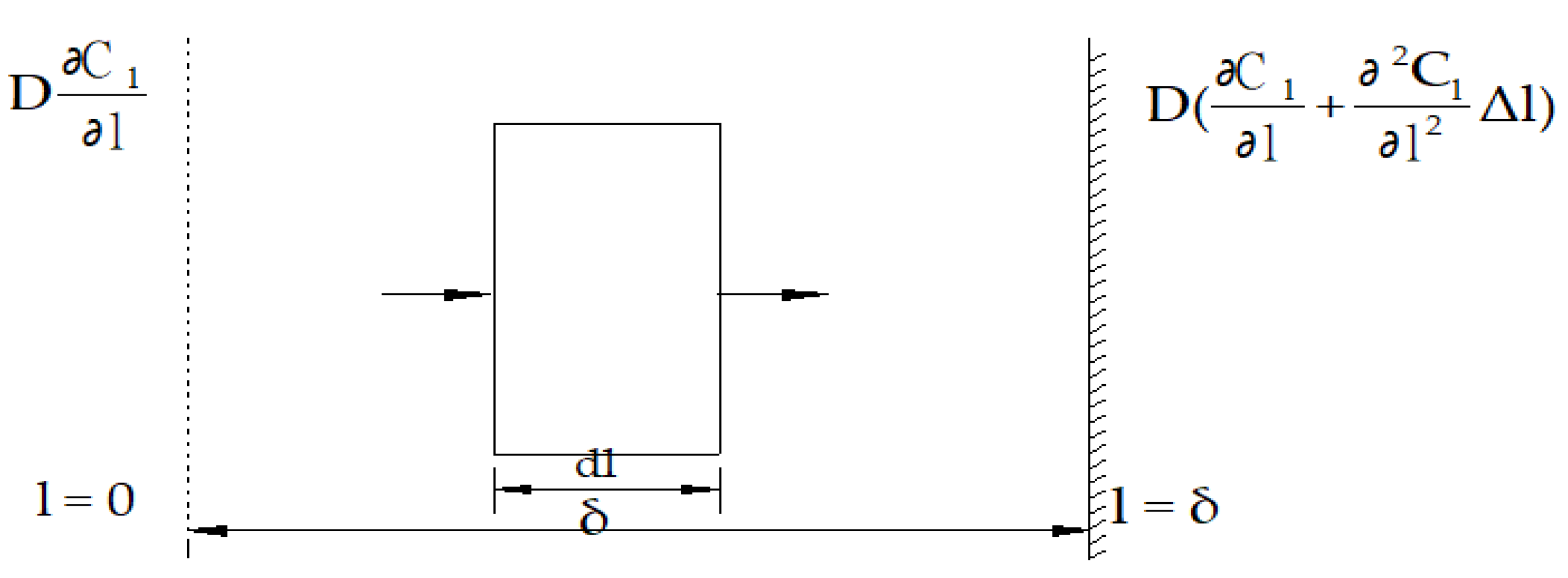
3.2. Dynamics Models

A microelement is taken within the biofilm, and a material balance equation is established for the microelement, as shown in Figure 2. The material balance equation for the substrate is as follows:
substrate entering the infinitesimal element − substrate leaving the infinitesimal element − substrate removed within the infinitesimal element = net change in the substrate within the infinitesimal element.
According to Fick’s law of molecular diffusion [35], the rate of mass transfer by diffusion through surface A is proportional to the substrate concentration gradient, such that:
F t = A D C l l ,
where F t represents interfacial mass transfer rate (10−6 mol/s), C l l represents the concentration gradient of the matrix within the biofilm (103 mol/m4), A represents the biofilm surface area (cm2), N represents the volume of the filler (m3), and l represents the thicknesses (cm). There is an equation between A and N (A = Nb, where b represents the specific surface area of the packing (m2/m3)). The rate of substrate removal by a biofilm can be expressed by the following equation:
1 X C l t = v = v m a x C l K s + C l ,
where Cl is the concentration of the substrate at depth l (mol/m3), v is the specific substrate removal rate for the substrate concentrations of Cl (h−1), X is the microbial concentration (X = Nbδρ); Δ is the thickness of the microbial membranes (cm), ρ is the bio-density of the microbial membranes (mg/m3), and Ks is the substrate reaction rate constant.
Substituting Equations (11) and (12) into the material balance equation, we obtain the following:
D C l l Δ y Δ x + D C l l + 2 C l l 2 Δ l Δ y Δ x ( C l l ) r e a c t i o n Δ y Δ x Δ l = ( C l t ) n e t Δ y Δ x Δ l .
At a steady state, we have the following:
( C l t ) n e t = 0 .
Thus, it follows that:
D d 2 C l d l 2 = ( d C l d t ) r e a c t i o n = ν m a x C l K s + C l N b δ ρ .
When Cl >> Ks, Equation (14) can be reduced to the kinetic equation for the zero-level reaction, as follows:
D d 2 C l d l 2 = ν m a x N b δ ρ .
Since the substrate concentration from the biofilm’s surface up to the solid surface satisfies the condition of Cl >> Ks, the boundary condition of Equation (15) can be written as follows:
When l = δ, d C l d l = 0 , and when l = 0, Cl = CB, where CB is the concentration after mixing (mol/m3), C B = Q C 0 Q C e V , V’ is the effective volume of the reactor (m3), C0 is the influent concentration (mol/m3), and Ce is the effluent concentration (mol/m3). The integral provides the following:
d C l d l = v m a x D N b δ ρ l + C l .
Using the boundary conditions, when l = δ, d C l d l = 0 and C l = ν m a x D N b δ 2 ρ , and we obtain the following:
d C l d l = ν m a x D N b δ ρ ( δ l ) .
Thus, it follows that the slope of l = 0 is as follows:
( d C l d l ) l = 0 = ν m a x D N b δ 2 ρ .
This leads to the specific surface area gradient of the substrate concentration packing within the biofilm at the point in time when the biofilm’s one-micron thickness is zero, without other external influences, leading to the following:
d F d t = A D d C l d l = ν m a x N 2 b 2 δ 2 ρ .
At this point, we see the following:
d F d t = Q d C d t .
Thus, it follows that:
Q d C d t = ν m a x N 2 b 2 δ 2 ρ .
Pirt and Saunders pointed out that the thickness of a microbial film can be obtained by assuming that all degradable organic matter on the solid surface is degraded, leaving only the non-degradable matter at a concentration of Cn. The thickness of a microbial film can be obtained by assuming that all degradable organic matter on the solid surface is degraded.
Integral (17) provides the following:
C l = 1 2 ν m a x D N b ρ δ l 2 ν m a x D N b ρ δ 2 l + C 2 .
When l = 0 and Cl = CB, it follows that C2 = CB, and we obtain the following:
C l = 1 2 ν m a x D N b ρ δ l 2 ν m a x D N b ρ δ 2 l + C B .
When l = δ, and if all the organic matter that can be degraded is degraded, it follows that Cl = Cn, and we obtain the following:
δ = [ 2 D ( C B C n ) ν m a x N b ρ ] 1 3 .
Substituting Equation (24) into (21) yields the following:
Q d C d t = 2 2 3 ν m a x 1 3 N 4 3 b 4 3 ρ 1 3 D 2 3 ( C B C n ) 2 3 . .
When Cl << Ks, Equation (14) simplifies to the following equations:
D d 2 C l d l 2 = ( d C l d t ) r e a c t i o n = ν m a x C l K s N b δ ρ   and
d C l d l = ν m a x N b ρ δ K s D C l 2 + C l .
At the surface of a solid substance, given that Cl = Cn and d C l d l = 0 , it follows that:
C l = ν m a x N b ρ δ K s D C n 2   and
d C l d l = ν m a x N b ρ δ K s D C l 2 C n 2 .
When l = 0 and Cl= CB, it follows that:
( d C l d l ) l = 0 = ν m a x N b ρ δ K s D C B 2 C n 2   and
d F d t = A D d C l d l = ν m a x N 3 b 3 D ρ δ K s C B 2 C n 2 .
Furthermore, under these conditions, we have the following:
d F d t = Q d C d t .
It follows that:
Q d C d t = ν m a x N 3 b 3 D ρ δ K s C B 2 C n 2 .
From Equation (29), we obtain the following:
l n ( C l C l 2 C n 2 ) = ν m a x N b ρ δ K s D l + C 2 .
Using l = 0 and Cl = CB, we obtain C 2 = l n ( C B C B 2 C n 2 ) and
l n ( C l C l 2 C n 2 ) = ν m a x N b ρ δ K s D l + l n ( C B C B 2 C n 2 ).
When l = δ and Cl = Cn, it follows that:
l n C B + C B 2 C n 2 C n = ν m a x N b ρ K s D δ 3 2 .
The derivation can be simplified by Equation (35) to yield the following:
δ = [ l n C B + C B 2 C n 2 C n · K s D ν m a x N b ρ ] 2 3 .
Substituting Equation (37) into Equation (33)’s yields, we obtain the following:
Q d C d t = ν m a x N 3 b 3 D ρ K s C B 2 C n 2 · [ l n C B + C B 2 C n 2 C n · K s D ν m a x N b ρ ] 1 3 = ν 2 3 m a x N 8 3 b 8 3 D 4 3 ρ 2 3 K s 2 3 C B 2 C n 2 · [ l n C B + C B 2 C n 2 C n ] 1 3 .
Equations (33) and (37) can be simplified to simplify the calculation. δ can be substituted into the calculation, and then Equation (24) is used in the calculation of the formula for the above equation.
In the presence of an electric field, it follows from the above derivation that when Cl >> Ks, in Equation (25), N and b are related to the nature of the filler when the filler is fixed for a fixed value, while vmax and Q are related to the nature of microorganisms when the operation is stabilized for a fixed value. We set K 1 = 2 2 3 v m a x 1 3 N 4 3 b 4 3 ρ 1 3 , and therefore, Equation (25) can be reduced as follows:
Q d C d t = K 1 D 2 3 ( C B C n ) 2 3 .
Because C B = Q C 0 Q C e V = 1 T ( C 0 C e ) , T is the dwell time and D = D r + a λ q E 6 π r η . Since λ, q, a, π, and η are constant values after the pollutant’s own composition remains unchanged and the operation is stabilized, we set k 1 = α λ q 6 π r η , and it follows that D = D r + k 1 E .
Thus,
Q d C d t = K 1 ( D r + k 1 E ) 2 3 [ 1 T ( C 0 C e ) C n ] 2 3 .
Correspondingly, δ = [ 2 D ( C B C n ) ν m a x N b ρ ] 1 3 , and if we let k2 = ( 2 V m a x N b ρ ) 1 3 , it follows that:
δ = k 2 ( D r + k 1 E ) 1 3 [ 1 T ( C 0 C e ) C n ] 1 3 .
When Cl <<Ks, if we let K 2 = ν 2 3 m a x N 8 3 b 8 3 D 4 3 ρ 2 3 K s 2 3 , then we can substitute K2 into Equation (38) to obtain the following:
Q d C d t = K 2 ( D r + k 1 E ) 2 3 [ 1 T ( C 0 C e ) ] 2 C n 2 · l n 1 T C 0 C e + [ 1 T ( C 0 C e ) ] 2 C n 2 C n 1 3 .
Also, if we let k 3 = ( K s ν m a x N b ρ ) 2 3 , then we can substitute k3 into Equation (37) to obtain the following:
δ = k 3 · ( D r + k 1 E ) 1 3 · { l n 1 T ( C 0 C e ) + [ 1 T ( C 0 C e ) ] 2 C n 2 C n } 2 3 .
The above step-by-step analysis of the relationship between the concentration gradient and the membrane thickness under different boundary conditions by analyzing the material balance of the trace amounts in the micro-electrolysis bioreaction system yielded Equation (37) for the membrane thickness calculation and Equation (38) for the reaction rate calculation. Subsequently, the relationship between the substrate concentration of a certain depth of material and its reaction rate under the action of an electric field is compared, and the equations for calculating the thickness of a micro-electrolytic biofilm and the reaction rate are deduced for the two states (high concentration and low concentration).

4. Discussion

Although micro-electrolysis technology has shown good results in water treatment, excessive energy consumption and system operating costs are still the main challenges in practical large-scale applications [19]. It can be seen that determining the most economical power consumption in the case of optimal treatment results is one of the key factors for the widespread application of this technology. Since an electric field can be used as an external driving force to accelerate the rate of ion diffusion, it can substantially accelerate the biofilm mass transfer process [7]. Voltage, electric field strength is the main factor affecting the mass transfer, and it should be in a range that ensures that the biofilm is not damaged, as the greater the electric field strength (in general, an electric field should be near 0.2 v/cm), the greater the rate of ion diffusion and the greater the amplitude of the mass transfer enhancement. The field should not be too large as this will cause the osmotic pressure on both sides of the biofilm to be too large such that the microorganisms become dehydrated or even die [23]. Under the condition of a certain electric field strength, the thicker the biofilm, the greater the enhancement factor. The use of electric field technology may be increase the volumetric loading of a biofilm, and at a low concentration, it can become the main driving force of mass transfer.

4.1. Relationship Between Electric Field Strength and Reaction Rate

Reaction rate usually accelerates with increasing current intensity, but too high a current may lead to excessive corrosion of the electrodes, affecting the stability and efficiency of the reaction, and so the micro-electrolysis reaction rate is modeled and experimentally investigated to determine the optimal operating parameters.
A comparison of Equations (40) and (42) shows that, regardless of the high or low concentrations of the pollutants in the treated water, the reaction rate is proportional to ( D r + k 1 E ) 2 3 . From the indicators of both, the intensity of the electric field has the same intensity of influence in the treatment of high and low concentrations of wastewater, and both have ( 1 + k 1 E D r ) 2 3 fold increases in the rates of the reactions compared to the rate of the reaction without the electric field.
Fixed retention time after the operation is stabilized. When treating highly concentrated wastewater, we see the following:
Q ( C 0 C e ) T = K 1 ( D r + k 1 E ) 2 3 [ 1 T ( C 0 C e ) C n ] 2 3 ,
and then
{ Q C 0 C e T [ 1 T ( C 0 C e ) C n ] 2 3 } 3 2 = K 1 2 3 D r + K 1 2 3 k 1 E .
Here, Q, T, K1, Dr, and k1 are all constant values, and so the original equation can be reduced to y = a + k E , where a and k are the intercept and slope of the primary linear equation.
When treating low concentrations of domestic wastewater, we see the following:
Q C 0 C e T = K 2 ( D r + k 1 E ) ) 2 3 [ 1 T ( C 0 C e ) ] 2 C n 2 · l n 1 T C 0 C e + [ 1 T ( C 0 C e ) ] 2 C n 2 C n 1 3 ,
and then
[ Q ( C 0 C e ) T ] 3 2 { [ 1 T ( C 0 C e ) ] 2 C n 2 } 3 4 · l n 1 T C 0 C e + [ 1 T ( C 0 C e ) ] 2 C n 2 C n 1 2 = K 2 3 2 D r + K 2 3 2 K 1 E .
Here, Q, T, K2, Dr, and k1 are all fixed values, and the original equation can also be reduced to y = a + k E . Meanwhile, a and k are found by the intercept and slope of a linear equation. It can be seen that the relationship between the electric field strength and the pollutant reaction rate in the micro-electrolysis biological reaction process can be simplified as a linear equation in the appropriate range of the electric field strength.

4.2. Relationship Between Electric Field Strength and Effluent Concentration

Whether the concentrations of pollutants treated by micro-electrolysis biotechnology meet the discharge standards or water reuse standards is the most direct goal of process optimization. As mentioned in Section 3, we can obtain the relationship between the electric field strength and the effluent concentration under both high and low concentration conditions.
When treating high-concentration organic wastewater, with a fixed residence time, according to Equation (40), Q d C d t = K 1 ( D r + k 1 E ) 2 3 [ 1 T ( C 0 C e ) C n ] 2 3 can be derived as Q ( C 0 C e ) T = K 1 ( D r + k 1 E ) 2 3 [ 1 T ( C 0 C e ) C n ] 2 3 , and with a negligible fraction of the Cn concentration of difficult-to-degrade organics in highly concentrated wastewater, Q ( C 0 C e ) = K 1 3 ( D r + k 1 E ) 2 T exists.
When treating domestic wastewater with a fixed dwell time, Equation (42),
Q d C d t = K 2 ( D r + k 1 E ) 2 3 [ 1 T ( C 0 C e ) ] 2 C n 2 · { l n 1 T ( C 0 C e ) + [ 1 T ( C 0 C e ) ] 2 C n 2 C n } 1 3 , can be derived as Q ( C 0 C e ) T = K 2 ( D r + k 1 E ) 2 3 [ 1 T ( C 0 C e ) ] 2 C n 2   ·   { l n 1 T ( C 0 C e ) + [ 1 T ( C 0 C e ) ] 2 C n 2 C n } 1 3 . For highly biochemical domestic wastewater, the biochemical coefficient γ = C 0 C n C 0 and both the numerator and denominator in { l n 1 T ( C 0 C e ) + [ 1 T ( C 0 C e ) ] 2 C n 2 C n } 1 3 are divided by C 0 , which can yield [ l n 1 T + 1 T 2 1 γ 2 1 γ ] 1 3 , and during this process, C e C 0 is negligible due to C e C 0 being too small. In the meantime, another part of the formula can be divided as [ 1 T ( C 0 C e ) ] 2 C n 2 = C 0 [ 1 T ( 1 C e C 0 ) ] 2 ( C n C 0 ) 2 = C 0 1 T 2 γ 2 , and we can set C 0 1 T 2 γ 2 · [ l n 1 T + 1 T 2 ( 1 γ ) 2 1 γ ] 1 3 as a constant m, and so the original equation is transformed to Q ( C 0 C e ) = m 2 K 2 2 ( D r + k 1 E ) 2 3 C 0 .
The relationship between electric field strength and pollutant effluent concentration is derived differently depending on the influent concentration. In the case of high concentrations, the strength of the electric field is quadratically related to the ratio of the difference between the pollutant effluent and discharge concentrations and the reaction time, while in the case of low concentrations, the strength of the electric field is a power function of the ratio of the difference between the pollutant effluent and discharge concentrations and the influent concentration.

4.3. Relationship Between Electric Field Strength and Biofilm Thickness

Biofilm thickness plays an important role in micro-electrolysis bioprocessing technology, affecting the microbial degradation efficiency, the electrolysis reaction effect, oxygen transfer, and system stability. A thin membrane thickness may lead to the ineffective degradation of pollutants by microorganisms, while a membrane that is too thick may lead to insufficient dissolved oxygen or limited microbial activity. Thicker biofilms may also lead to reduced efficiency of the electrolysis reaction and uneven distribution of the electric field, which, in turn, affects the production of electrochemical substances and microbial degradation [36]. Biofilm thickness detection is a complex process, and the thickness may be uneven at different locations [37]. Biofilm thickness may change in real time over time [38], especially in complex water treatment systems where the thickness of a membrane may be affected by flow rate, contaminant distribution, microbial species, and other factors, and the interference of environmental factors is also an important influencing factor. In addition, existing testing methods often require sophisticated instruments and more complex operations, and they lack a unified standardized operation specification [39]. In Section 3 of this paper, the relationship between the electric field strength and the thickness of a biofilm formed in a micro-electrolysis bioreactor can be deduced based on the two cases of high and low influent water concentrations.
When treating high-concentration wastewater, it can be seen from δ = k 2 ( D r + k 1 E ) 1 3 [ 1 T ( C 0 C e ) C n ] 1 3 , that the thickness of the microbial membrane is directly proportional to ( D r + k 1 E ) 1 3 , and as the electric field strength increases, the microbial membrane thickens. Meanwhile, when treating low-concentration domestic wastewater, it can be seen from δ = k 3 · ( D r + k 1 E ) 1 3 · { l n 1 T ( C 0 C e ) + [ 1 T ( C 0 C e ) ] 2 C n 2 C n } 2 3 , that the thickness of a microbial membrane is directly proportional to ( D r + k 1 E ) 1 3 . As electric field strength is increased, microbial films thicken. Comparing the indices of the two, the electric field strength had the same strength of effect on biofilm thickness. Compared with the thickness of the microbial film formed without the electric field, there was a ( 1 + k 1 E D r ) 1 3 fold increase in both the low and high concentrations, and both microbial films thickened with the increases in field strength.

5. Conclusions

The innovation of this study is to establish the relationship between electric field strength and biofilm thickness and pollutant reaction rate. Through the macro process operation parameters monitored by the micro-electrolysis biological treatment experiment, such as inlet and outlet water pollutant concentrations, hydraulic retention time, voltage, and the basic physical and chemical property parameters of the water environment, the electric field strength in the micro-electrolysis biological reaction system could be calculated, and the biofilm thickness was calculated through the electric field strength. This can provide theoretical data for monitoring the treatment effect of a biofilm reaction system on pollutants. The specific conclusions are as follows:
(1)
Under the goal of realizing the efficient removal of pollutants, the relationship between the electric field strength and the pollutant reaction rate can be simplified as a linear equation in the appropriate voltage range.
(2)
In the case of a high concentration, the electric field strength is quadratic with the ratio of the difference between the concentrations of pollutants in and out of the water and the reaction time; in the case of a low concentration, the electric field strength is power-functional with the ratio of the difference between the concentrations of pollutants in and out of the water and the concentration of the water inlet and outlet.
(3)
There is a ( 1 + k 1 E D r ) 1 3 fold increase in microbial film thickness in a micro-electrolysis bioreactor compared to the thickness of a microbial film formed in the absence of an electric field, and it becomes thicker with increases in electric field strength.
We have successfully constructed a relationship between the two reaction processes in micro-electrolysis biotechnology, which provides a new approach to probe the interaction mechanism between the two. However, despite the breakthrough in theoretical calculations, we still need to address the limitations of the constructed model in terms of simplifications and assumptions that do not fully reflect the complexity of the actual operation, as well as the accuracy of the experimental data to verify the kinetic equations. In order to further enhance the effectiveness of micro-electrolysis biological treatment technology and the stability of system operation, future research will focus on optimizing the existing kinetic model, especially considering the effects of process parameters, pollutants, and electrode surface reactions, as well as the interference of other ions and substances in the water, in order to overcome the current limitations and to provide theoretical data for optimizing the process parameters to achieve a balance between efficiency, energy consumption, and carbon emissions to promote the sustainable development of the technology.

Author Contributions

X.Z. and L.P. conceived and designed the study. X.Z. derived the formulas and wrote the manuscript. Z.Z. conducted the literature search and assisted in drafting the manuscript. J.X. and J.Z. provided valuable insights during the data analysis phase and helped interpret the results. T.H. assisted with the experimental design and contributed to the manuscript’s editing and final revisions. All authors have read and agreed to the published version of the manuscript.

Funding

This research was funded by [the independent research projects of the Engineering Research Center of Coal-Based Ecological Carbon Sequestration Technology of the Ministry of Education Open Fund, Shanxi Datong University] grant number [MJST2022-07].

Institutional Review Board Statement

This study does not involve humans and animals.

Informed Consent Statement

This study does not involve any humans.

Data Availability Statement

This study does not report any data.

Acknowledgments

The authors greatly appreciate Yongzhi Zhao for his supervision and guidance throughout the entire study, and they acknowledge the helpful suggestions and feedback of the anonymous reviewers.

Conflicts of Interest

The authors declare no conflicts of interest.

References

  1. Shi, R.; Hong, Y. Research on the application of new sewage treatment technologies in water environment protection. Hydropower Sci. Technol. 2024, 7, 122–124. [Google Scholar]
  2. Zou, Z.; He, S.; Han, C.; Zhang, L.; Luo, Y. Research progress on heavy metal wastewater treatment technologies. Ind. Water Treat. 2010, 30, 9–12. [Google Scholar]
  3. Zhang, Z. Technological innovation and energy-saving and consumption-reduction research in sewage treatment. Eng. Constr. Manag. 2023, 1, 4–6. [Google Scholar]
  4. Ren, J.; Wu, C.; Yang, Z.; Wang, R.; Yang, L.; Tao, L. Study on the treatment of domestic wastewater using iron-carbon fillers coupled with biofilm method. Water Treat. Technol. 2025, 51, 90–96+113. [Google Scholar]
  5. Xu, G.Y. Study on the Performance of Iron-Carbon Micro-Electrolysis and Iron Oxide Coupled Biological Denitrification. Master’s Thesis, Chang’an University, Xi’an, China, 2023. [Google Scholar]
  6. Hu, B. Study on Treatment of Pharmaceutical Wastewater by Combined Process of Ferric-Carbon Micro Electrolysis-Biochemical Technology. Master’s Thesis, Chongqing University, Chongqing, China, 2008. [Google Scholar]
  7. Zhao, M.; Fan, J.; Ma, L. Mechanism and application of electro-biological technology for enhanced wastewater treatment. Sichuan Environ. 2010, 29, 55–60. [Google Scholar]
  8. Qi, Y. Study on the Process and Equipment of Iron-Carbon Micro-Electrolysis-Biofilm Method-Advanced Oxidation for Textile Wastewater Treatment. Master’s Thesis, Jiangsu University, Zhenjiang, China, 2018. [Google Scholar]
  9. Li, L.; Chen, J.; Liao, M.; Su, D.; Zhu, J.; Li, X. Application and research of iron-carbon micro-electrolysis technology. Environ. Sci. Manag. 2017, 42, 98–101. [Google Scholar]
  10. Zhang, J. Treatment of Plating Wastewater with Heavy Metal Ions by Micro-Electrolysis and Biofilm Process. Master’s Thesis, Tianjin University, Tianjin, China, 2005. [Google Scholar]
  11. Sun, Q.; Yin, Y.; He, Y.; Yu, L.; Liang, X.; Wang, G.; Zhao, B. Study on the purification effect of electrolysis-enhanced constructed wetlands under low-temperature conditions for simulated low-pollution water. Front. Environ. Prot. 2021, 11, 938–945. [Google Scholar]
  12. Ling, H. Study on the Electrochemical-Biological Method for Treating Typical PPCPs. Master’s Thesis, Beijing University of Chemical Technology, Beijing, China, 2011. [Google Scholar]
  13. Ma, W. Enhanced Treatment of Phenolic Compounds in Coal Gasification Wastewater by Micro-Electrolysis Coupled Biological Process. Ph.D. Thesis, Harbin Institute of Technology, Harbin, China, 2020. [Google Scholar]
  14. Liu, X.; Huang, X.; Jin, W. Study on Simultaneous Nitrification and Denitrification in Electrode Biofilm Reactors. Ind. Water Wastewater 2009, 40, 42–45. [Google Scholar]
  15. Cong, L.; Zheng, T.; Xie, Z. Micro-Electrolysis/Coagulation/Anaerobic Membrane Bio-Reactor Combined Process for High-Concentration Landfill Leachate Treatment. J. Xiamen Univ. (Nat. Sci.) 2006, 45, 824–827. [Google Scholar]
  16. Cao, L.; Zhang, S.; Zhang, Y.; Deng, X.; Lu, Y. Research Progress of Micro-Electrolysis Materials. Mod. Chem. Ind. 2015, 35, 13–17. [Google Scholar]
  17. Wang, S.; Zhou, P. Kinetic Mechanism of Organic Matter Degradation in Biological Fluidized Beds. J. Southeast Univ. (Nat. Sci. Ed.) 1993, 23, 62–68. [Google Scholar]
  18. Liu, Y.; Wang, Q. Biofilm Growth Kinetic Model. J. Beijing Technol. Univ. (Nat. Sci. Ed.) 1997, 2, 28–31. [Google Scholar]
  19. Zhou, Z.; Lu, R.; Ye, C.; Yue, S.; Li, J.; Li, Y. Application of PLC Control in Treatment of Rubber Wastewater by D-A2O Combination Technology. China Water Wastewater 2018, 34, 5. [Google Scholar]
  20. Beshkov, V.; Velizarov, S.; Agathos, S.N.; Lukova, V. Bacterial denitrification of wastewater stimulated by constant electric field. Biochem. Eng. J. 2004, 17, 141–145. [Google Scholar] [CrossRef]
  21. Jiang, B. Study on the Efficiency and Mechanism for Phenolic Wastewater Treatment by Coupled System of Biochar-Electric Field Attached Membrane Bioreactor. Ph.D. Thesis, Harbin Institute of Technology, Harbin, China, 2020. [Google Scholar]
  22. Zhong, F.; Cao, H.; Li, X. Biochemical mass transfer model of biofilm under external electric field. J. Jilin Chem. Eng. Univ. 2003, 4, 59–61. [Google Scholar]
  23. Jia, H.; Yan, L.; Li, X.L. Application of electrostatic technology in cell engineering. Electrostatics 1988, 3, 23–26. [Google Scholar]
  24. Kong, Q. Research and application of advanced treatment technology for domestic wastewater. Mar. Eng. Equip. Technol. 2019, 6, 409–413. [Google Scholar]
  25. Li, J. Study on the Enhancement of Tetrabromobisphenol A Degradation by Three-Dimensional Electrode Biofilm Reactor. Master’s Thesis, East China Normal University, Shanghai, China, 2024. [Google Scholar]
  26. Kang, M. Study on the Combined Treatment of Oily Ballast Water from Ships by Iron-Carbon Micro-Electrolysis and Biofilm Method. Master’s Thesis, Zhejiang Ocean University, Zhoushan, China, 2019. [Google Scholar]
  27. Xiong, C. Mathematical Model Establishment and Study on Algae-Bacteria Symbiotic System for Treatment of Livestock and Poultry Breeding Wastewater. Master’s Thesis, Nanchang University, Nanchang, China, 2023. [Google Scholar]
  28. Deng, Q. Study on optimization and application of biofilm reactor in specific industrial wastewater treatment. Heilongjiang Environ. Bull. 2024, 37, 12–14. [Google Scholar]
  29. Dou, H. Study on Dynamics and Thermodynamics of Sulfate-Reducing Bacteria Biofilm. Master’s Thesis, China University of Geosciences (Beijing), Beijing, China, 2023. [Google Scholar]
  30. Yang, P.; Guo, Y.; Shi, Y.F. Study on settling performance of porous biological particles and bed expansion characteristics in a biofilm fluidized bed. Chem. Eng. Process. 2003, 19, 8. [Google Scholar]
  31. Pau, P.C.F.; Berg, J.O.; McMillan, W.G. Application of Stokes’ law to ions in aqueous solution. J. Phys. Chem. 1990, 94, 2671–2679. [Google Scholar] [CrossRef]
  32. Shearer, S.A.; Hudson, J.R. Fluid mechanics: Stokes’ law and viscosity. Meas. Lab. 2008, 3, EGR 101. [Google Scholar]
  33. Chen, B.; Wang, J.; Zhang, R.J. How is the Lorentz force formula given. College Phys. 2008, 27, 42. [Google Scholar]
  34. Pan, J.; Tong, J.M.; Tian, M.B. Fundamentals of Materials Science (Revised Edition); Tsinghua University Press: Beijing, China, 2011. [Google Scholar]
  35. He, L.; Lin, J.; Shi, B. Fick’s law and the thermodynamic theory of diffusion. J. Anqing Teachers Coll. Nat. Sci. Ed. 2006, 4, 38–39. [Google Scholar]
  36. Zhou, P.; Wang, S. Effect of biofilm thickness on the performance of fluidized bed reactors. Environ. Sci. 1994, 2, 1–5+92. [Google Scholar]
  37. Qiu, L.; Ma, J. Biofilm and microbial community characteristics in an aerated biofilter. Chin. Environ. Sci. 2005, 25, 4. [Google Scholar]
  38. Zhao, Y. Growth and Variation Characteristics of Biofilm on Semi-Suspended Carriers. Master’s Thesis, Guangdong University of Technology, Guangzhou, China, 2017. [Google Scholar]
  39. Wang, Z. Study on Plastic Optical Fiber Sensor for Accurate Online Measurement of Microalgae Biofilm Thickness. Master’s Thesis, Chongqing University of Technology, Chongqing, China, 2019. [Google Scholar]
Figure 2. Planar biofilm reactor model.
Sustainability 17 01105 g002
Figure 1. Schematic representation of pollutant diffusion within a biofilm.
Sustainability 17 01105 g001
Disclaimer/Publisher’s Note: The statements, opinions and data contained in all publications are solely those of the individual author(s) and contributor(s) and not of MDPI and/or the editor(s). MDPI and/or the editor(s) disclaim responsibility for any injury to people or property resulting from any ideas, methods, instructions or products referred to in the content.

