Abstract
This research focuses on the design and implementation of a movement strategy for a photovoltaic (PV) system, presented through four phases: First came the design of the mechanical part and the selection of geared motors with high torque and low power consumption, while having a solid mechanical structure that supports the panel. An open-loop control was selected using solar positioning equations, with the inputs defined as solar equations. The Intel Edison development board was chosen for programming the solar equations in Python. Two linear potentiometers served as sensing elements, where analog–digital characterization was conducted for each movement. The plant started with the static panel at a latitude of 7° south, oriented toward the equator, achieving a performance of 177.62 kWh. With the solar tracker, a performance of 232.38 kWh was obtained, resulting in an efficiency increase of 27%. Given the aim of enhancing PV efficiency through increased utilization, satisfactory results were achieved. Another advantage of the unit is that it is designed to support more than one panel.
1. Introduction
The use of photovoltaic (PV) systems is a viable and sustainable solution for electricity generation in rural and remote areas, especially in developing countries where energy demands and the need to reduce environmental impacts are increasing. A study conducted in Brazil demonstrated that a PV system with dual-axis solar tracking increased energy generation by 26% compared to a fixed panel. However, on cloudy days or during periods of high rainfall, the efficiency of the tracking system decreased [1]. Similarly, studies in tropical regions, such as in Africa, have shown that solar tracking technologies can significantly improve energy yields, even in regions with variable weather conditions, though challenges related to cloud cover and rainfall still impact efficiency [2]. Solar tracking systems (STS) play a key role in optimizing the efficiency of solar panels. According to a review of methods, single-axis trackers, based on astronomical calculations and navigation sensors, can outperform fixed installations by up to 27.4%, while dual-axis trackers, which employ trajectory calculations, can achieve an increase of 37.65%. Adapting the system design to local climatic conditions is essential for maximizing efficiency [3]. Additionally, a performance analysis in tropical climates with a solar tracking system (STS) equipped with a maximum light detection algorithm (MLD) showed significant improvements in energy generation, even under cloudy skies. This suggests that intelligent algorithms can mitigate the negative effects of adverse weather conditions [4]. Finally, innovative approaches to energy optimization in tropical climates have been explored through passive strategies, such as the use of vertical green trellises. A study in Panama demonstrated that these systems significantly reduced the cooling needs of buildings, although they increased the demand for lighting. These results underscore the importance of the optical and radiative properties of vegetation in maximizing energy efficiency in tropical climates [5].
More nuanced analyses have highlighted the value of real-world data when assessing dual-axis tracking performance. For example, a study in Hungary compared simulated and real data for monocrystalline, polycrystalline, and amorphous silicon modules. The study found that the simulated results often overestimated the performance by approximately 10%, demonstrating the importance of real-world measurements. These results are particularly relevant when evaluating specific energy outputs across different PV technologies and configurations, as they facilitate planning and investment decisions by providing a realistic understanding of performance under operational conditions [6].
Solar tracking is the most suitable technique for increasing the efficiency of photovoltaic (PV) systems, and the literature proposes two main approaches. The first, closed-loop, utilizes active sensors that detect the sun’s position in real time. These sensors, which may include devices such as photodetectors or torque sensors, provide precise data that allow for continuous adjustment of the panel’s tilt and orientation. This method is particularly effective under changing conditions, as it responds immediately to variations in sunlight [7,8,9,10,11]. However, the cost and complexity of implementing and maintaining these sensors can pose challenges, especially in remote areas or regions with limited resources. On the other hand, the open-loop approach uses mathematical and astronomical models to calculate the sun’s position based on the date, time, and geographical location. This method relies on the premise that, although sensors are not used, solar trajectories can be predicted with high precision. This allows for pre-established adjustments of the panels, albeit with less flexibility under variable weather conditions [12,13,14,15]. This approach may be less costly to implement, as it reduces the dependence on electronic components and sensors, but it requires a precise understanding of solar calculation algorithms and their application.
Expanding beyond conventional PV applications, the integration of solar tracking systems into concentrated solar power (CSP) technologies with central receivers has gained traction. CSP systems, which utilize solar tracking to focus sunlight onto a central tower, can achieve significant energy efficiency improvements. When hybridized with PV systems, the combined PV-CSP approach leverages spectral beam-splitting or PV-topping techniques to maximize the energy capture. Studies have revealed that such hybrid configurations not only improve the quality of power generation but also reduce costs compared to standalone CSP systems. The compact integration of these technologies has the potential to enhance the overall efficiency and accelerate the adoption of renewable energy [16].
Moreover, the efficiency of photovoltaic (PV) systems is influenced by a variety of internal and external factors. Internal factors include the characteristics of the solar panels themselves, such as the materials used, manufacturing quality, and ohmic losses in connections, which can lead to significant differences in the efficiency of converting solar energy into electricity. On the other hand, external factors are equally crucial. Geographical location determines solar exposure and the amount of available radiation, while the intensity and angle of incident solar radiation affect energy capture. Weather conditions, such as cloudiness and rainfall, can decrease the amount of available sunlight, negatively impacting energy production. Additionally, the accumulation of dust and dirt on the panel surface obstructs the radiation that strikes them, further reducing their efficiency. Therefore, it is essential to consider all these factors when designing and operating photovoltaic (PV) systems and solar tracking systems (STS).
Recent innovations in solar tracking mechanisms have demonstrated the potential for significant improvements in energy efficiency. A dual-axis solar tracker implemented in hardware improved the energy efficiency by over 23.6% for normal tracking and by 31.8% for daily adjusted tracking. These systems incorporate azimuthal and elevation mechanisms controlled by closed-loop feedback systems, which continuously adjusted panel orientation based on solar intensity. This level of precision ensures minimal cosine losses and makes the dual-axis configuration suitable for both PV and CSP applications. Additionally, closed-loop systems reduce the inefficiencies caused by abrupt changes in sunlight, making them particularly valuable in regions with intermittent cloud cover [17,18].
This article presents a strategy for a photovoltaic (PV) system with a dual-axis solar tracking unit in Bucaramanga, a city with a solar potential of 4.9 kWh/m²/day. Given that there have been few studies on solar trackers in tropical climates, this work aimed to maximize the solar energy capture by optimizing the panel’s orientation based on its elevation and azimuth, which is of great relevance to the tropical context. The system was designed using solar positioning equations, allowing for precise calculation of the sun’s location at each moment of the day. Implementation was carried out using an Intel Edison development board, enabling calculations to be performed in an open loop, thereby eliminating the need for active sensors such as light-dependent resistors (LDRs) or torque sensors. This approach was adopted due to the novelty of the system and to reduce the complexity and cost of implementation, making the most of mathematical and computational resources. Thus, the project offers an innovative and efficient solution for solar tracking in a tropical climate, contributing to the development of more efficient photovoltaic (PV) systems in regions with similar characteristics.
2. Materials and Methods
The methodology for developing the solar tracking system was structured in several phases, each addressing a critical aspect of the design and implementation of the system. These phases were as follows:
2.1. Phase 1: Study of Solar Positioning Equations
In this initial phase, a thorough study of the solar positioning equations was conducted, which are fundamental for calculating the position of the sun based on the date, time, and geographical location. This step is particularly important in a tropical climate, where the solar incidence can vary significantly throughout the day and across seasons. Understanding these equations allows optimization of the performance of the tracking system, ensuring that the photovoltaic panel is optimally oriented to capture the maximum amount of solar radiation possible.
2.2. Phase 2: Design and Construction of the Mechanical Part of the Solar Tracker
In Phase 2 of the design and construction of the solar tracker, the actuators and transmission systems were carefully selected to ensure efficient and precise operation of the solar tracking system. The actuators play a crucial role in moving the photovoltaic panel, allowing it to be oriented in two degrees of freedom: azimuth (horizontal orientation) and solar altitude (tilt). In particular, the DFS10G-05 servo-gearmotors (Tuff Automation, Grand Rapids, MI, USA). were chosen, due to their low cost, energy efficiency, and the presence of encoders, which are essential for accurately measuring the position of the solar panel during movement [19].
The encoders installed in these actuators provide precise information about the angular position of the panel in real time. These encoders are critical for ensuring that the tracking system keeps the photovoltaic panel aligned with the sun throughout the day. The rotary encoders used in the motors allow for an accurate reading of the panel’s position, facilitating the necessary adjustments to maintain the optimal orientation in both the azimuth and elevation movements.
For movement transmission, worm-gear reducers were used, selected for their ability to “lock” the movement when the coupling angle between the crown and the screw is close to 90°. This feature is essential for keeping the solar panel in position without the need for continuous excitation of the actuators. The reduction ratio in the selected reducers ensures that the output speeds are low, approximately 0.05 rpm for the azimuth movement and 0.2 rpm for the solar height, which is suitable for achieving efficient solar tracking without compromising the energy consumption.
Regarding the transmission to the base axis of the photovoltaic panel support, a chain–pinion mechanism with a 1:1 transmission ratio was chosen due to its long lifespan and low cost. This mechanism, along with the selected actuators, allows for precise and reliable control of the solar panel’s movement, maximizing solar energy capture under various weather conditions.
2.3. Phase 3: Implementation of the Control System
After completing the mechanical part, the control system was developed and implemented. This phase involves programming the microprocessor (such as the Intel Edison) that will execute the control algorithm based on the solar positioning equations. Implementing an effective control system is crucial for accurately adjusting the tilt and orientation of the panel, responding to changes in the sun’s position throughout the day. Selecting an appropriate control system ensures that the solar tracking system operates efficiently and maximizes the solar energy capture.
2.4. Phase 4: Integration and Testing of the System
The final phase involved integrating all components and conducting tests of the system under real conditions. During this stage, the performance of the system was monitored, calculating the instantaneous power generated by the photovoltaic panel at different times of the day. The results of the active tracking system were compared with those of a static panel to evaluate the system’s efficiency. This testing phase was essential for validating the design and making necessary adjustments to improve the performance and reliability.
The calculation of the solar position is performed relative to a terrestrial position using astronomical equations of solar positioning. The data needed for these calculations are primarily the date, time, time zone, and position in terms of latitude and longitude of the observer. Solar trackers use sensors to determine the position in which the greatest solar radiation is captured. Photocells or photodetectors located in a matrix are used to obtain differences in the amount of solar radiation perceived, or industrial sensors measure the angle of incidence of the sun’s rays, capable of delivering the position of the sun through a digital signal.
Some solar trackers use digital image processing techniques to position the photovoltaic panel perpendicular to the sun’s rays. Unlike the previously mentioned tracking systems, astronomical methods (solar maps, solar positioning equations) are used to calculate the angular position of the sun (azimuth and solar height) using data such as latitude, longitude, date, time, and time zone, which can be supplied manually or using a GPS (global positioning system).
Regarding the hardware used, microcontrollers, PLCs, and FPGAs are prominent for performing control over the actuators. These can be implemented with ON/OFF controls; digital PID controllers; and optimization techniques, neural networks, or embedded systems.
The experimental unit was developed in several phases. The first phase involved constructing the mechanical part and supports of the photovoltaic panel, with a protective box for the selected electronic circuits and the selection of the DFS10G-05 geared motors. The experimental unit was designed to support and move an UPSOLAR photovoltaic panel of 250 Wp and 18.5 kg, in two degrees of freedom: solar height (inclination) with an operating range between 40° and 120°, and azimuth (orientation) with a range of 360°.
In the second phase, a study of the most suitable approach for a tropical climate was carried out, where the open-circuit approach was selected due to climate changes in the city of Bucaramanga. The proposed approach uses a tracking or control algorithm concerning the azimuth position, and the elevation angle of the sun is determined by solar movement algorithms according to the given date, time, and geographic information.
In the third phase, the Intel Edison microprocessor was selected to control and program the azimuth and elevation positioning, with the control algorithm executed on a Linux Yocto operating system, enabling the WiFi communication protocol for pedagogical support. In the fourth phase, two linear resistances were selected (one for each movement) to determine the real position of the tracker concerning the elevation and azimuthal position.
The test was executed from 9:00 a.m. to 4:00 p.m., calculating the instantaneous power generated by the solar tracker with the static panel every 30 min, at approximately 7° looking at the equator, and comparing the results obtained with the active tracker, where greater efficiency was achieved than with the static panel.
3. Phase 1: Calculation of the Solar Position
In this phase, we focused on determining the solar position using the relevant equations. The two critical parameters for a solar tracker are the elevation and azimuth positions [20,21,22].
3.1. Solar Position Calculation
The relative position of the sun with respect to an observer on Earth can be determined using solar positioning equations. These calculations depend on parameters such as the date, time, time zone, latitude, and longitude of the observer. The steps and equations required for this process are detailed below.
3.2. Fraction of the Year Elapsed
The first step is to calculate the fraction of the year that has elapsed, represented by the angle (in radians). This is computed using the following equation:
where
- day: Day of the year (1 to 365).
- hour: Local time in hours.
The parameter is crucial for the subsequent calculations, as it represents the Earth’s position in its orbit around the sun at a given date and time.
3.3. Equation of Time
The difference between the mean solar time (MST) and apparent solar time (AST) is represented by the Equation of Time. This discrepancy arises due to the elliptical shape of the Earth’s orbit and the tilt of its axis. The Equation of Time is given by
The Equation of Time provides the deviation in minutes of AST from MST on different days of the year.
3.4. Solar Declination
The solar declination is the angle between the sun’s rays and the Earth’s equatorial plane. It varies between and throughout the year. The declination is calculated as follows:
This parameter is critical for determining the sun’s position relative to the Earth’s surface.
3.5. Relative Earth–Sun Distance
The relative distance between the Earth and the sun, represented as , accounts for variations in solar intensity due to the Earth’s elliptical orbit. It is calculated using
This factor is used in solar radiation models to adjust for the Earth’s varying distance from the sun.
3.6. Apparent Solar Time (AST)
The apparent solar time (AST) is calculated by correcting the local time with the Equation of Time, longitude, and the time zone offset:
where
- day: Day of the year (1 to 365).
- hour: Local time in hours.
3.7. Hour Angle
The hour angle represents the angular displacement of the sun from the observer’s local meridian. It is computed as
3.8. Solar Elevation
The solar elevation is the angular distance between the sun and the observer’s horizon. It is calculated using
The solar altitude h is then
3.9. Solar Azimuth
The solar azimuth is the angle measured clockwise from true north to the projection of the sun on the horizontal plane. It is given by
4. Phase 2: Design and Construction of the Electromechanical System
The second phase focused on the design and construction of the electromechanical system for the solar tracking unit, based on the characteristics of the Upsolar UP-M250P photovoltaic panel, which consists of 60 polycrystalline silicon cells. The system is designed to allow two degrees of freedom—azimuth and solar elevation—to maximize the collection of incident solar radiation [23].
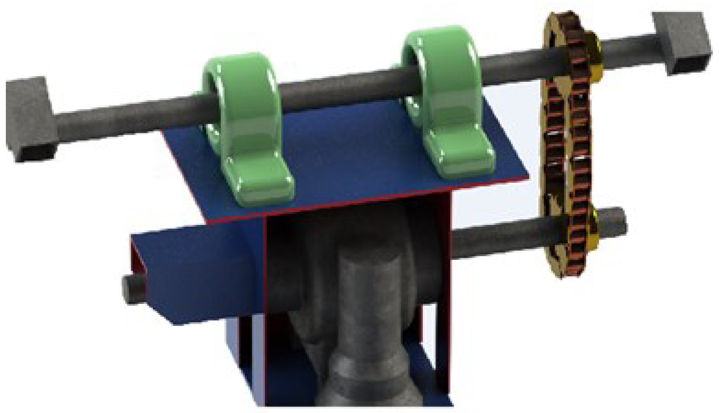
A preliminary sketch of the mechanical transmission system was created using SolidWorks (Figure 1), which depicted the key components involved in the movement of the photovoltaic panel. This design included the integration of the actuators, gears, and structural elements necessary to achieve the required degrees of freedom—azimuth and solar elevation. The SolidWorks model provides a clear representation of how the transmission system will function to ensure precise tracking of solar radiation.

Figure 1.
Sketch of the mechanical transmission system created in SolidWorks. The figure was created by the authors.
4.1. Mechanical Design
The solar panel was mounted on an H-shaped support constructed from 1” iron angles, providing the necessary stability during movement (Figure 2). To protect the control circuit and actuators, a protection base made of steel was built, consisting of a cubic structure with 4 mm thick steel plates. This base also facilitates azimuth movement by housing the necessary mechanical components, while allowing airflow through cutouts in the structure.
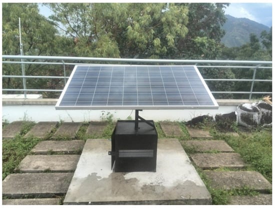
Figure 2.
Mechanical section completed and installed. The figure was created by the authors.
4.2. Actuation System
To control the movement of the panel in azimuth and elevation, DFS10G-05 geared motors were selected, due to their low power consumption and integrated encoders. These actuators drive the panel’s movement, ensuring precise control of both degrees of freedom, without excessive energy consumption, which is crucial for the system’s efficiency [19].
4.3. Turning Units and Transmission System
Given the high nominal speed of the actuators, speed reducers were introduced to decrease the operating speed to appropriate levels for solar tracking. These reducers ensure smooth and slow movements that align the panel with the sun throughout the day. For the transmission of motion to the solar height support, a mechanism was implemented using toothed pulleys and a chain-sprocket system. This transmission allows for stable and reliable movement as the panel tilts during the day.
5. Phase 3: Design and Implementation of the Control Module
5.1. Selection of Processing Hardware
For the design and implementation of the control module, the Intel Edison development platform was selected. This platform features a 22 nm Intel Atom SoC that includes a 500 MHz dual-core Intel CPU and a 100 MHz 32-bit Intel Quark microcontroller. It supports 40 GPIOs and comes with 1 GB of LPDDR3 memory, 4 GB of EMMC storage, dual-band WiFi (2.45 and 5 GHz), and Bluetooth 4.0 [24].
The official operating system (OS) is Yocto, which is based on GNU/Linux, allowing the execution of algorithms described in high-level programming languages such as Python and C/C++ (Yocto Project, version from 2016).
Furthermore, Intel provides support tools like Eclipse and Intel XDK, enabling the use of Node.js and HTML5 for web application design with python2021 [25].
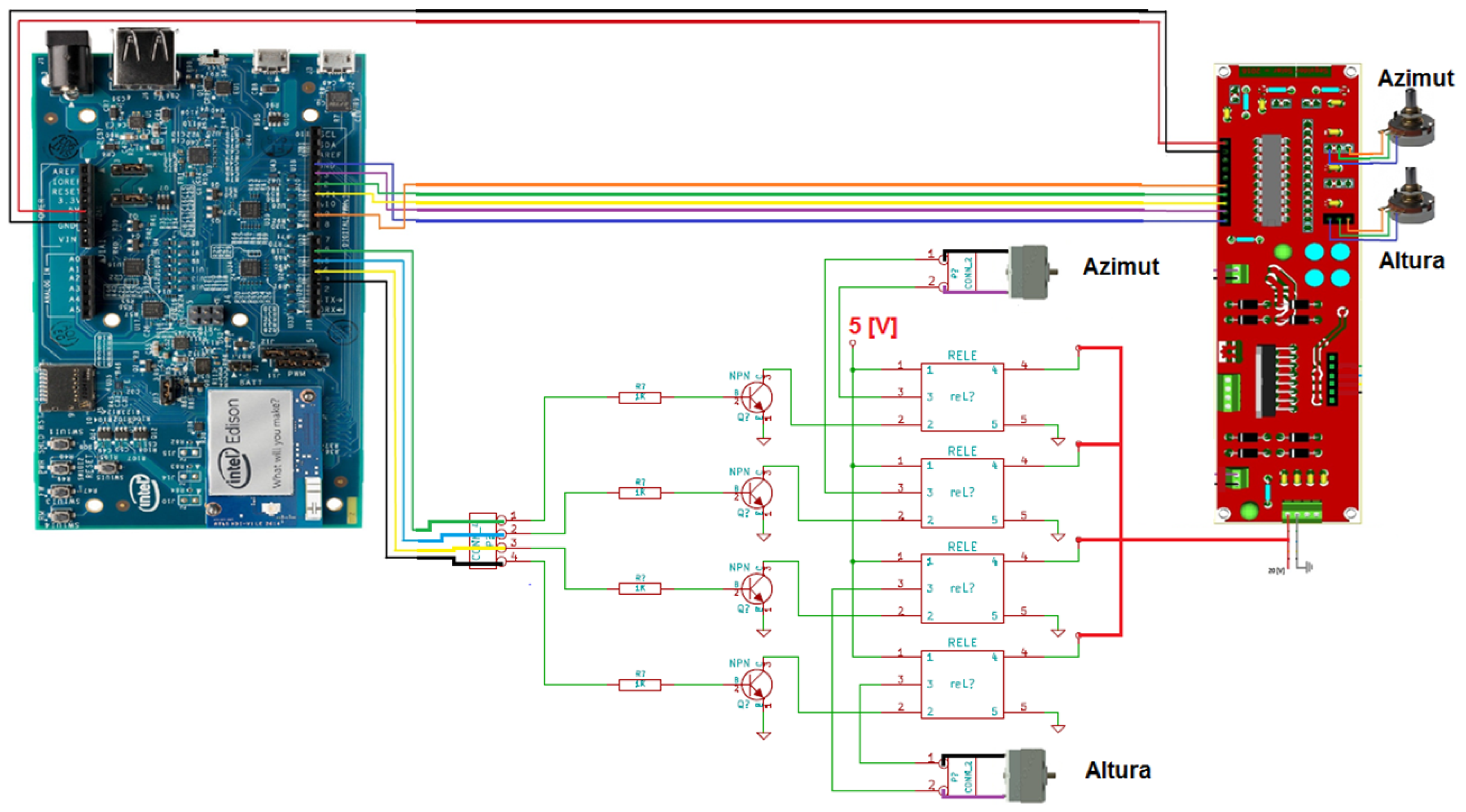
5.2. Control System
Considering that the relative movement of the sun concerning the Earth is predictable, an open-loop control system based on solar positioning equations was implemented. The input variables for these equations include the date, time, time zone, latitude, and longitude of the installation site. From these data, the apparent position of the sun is estimated in terms of azimuth and solar height. At each time interval , a readjustment of the position is made if necessary, and the displacement is not restricted by the range of motion for each degree of freedom. The control schematic is presented with the Intel Edison and the electronic system (see Figure 3).
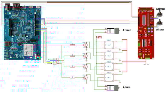
Figure 3.
Open-loop solar tracker control system.
5.3. Power Module Design
The design of the power module required a system that can supply electrical power and control the direction of rotation of the actuators. It must be capable of handling current peaks of 1.7 A to meet the power requirements of the actuators at startup, after which a constant current of 350–500 mA is needed.
To address this need, the L298N [26] integrated circuit was selected. This circuit has two channels, supports continuous operation of up to 2 A per channel, and can handle non-repetitive current peaks of up to 3 A with a power supply voltage of 50 V. The power circuit diagram is illustrated in Figure 4.
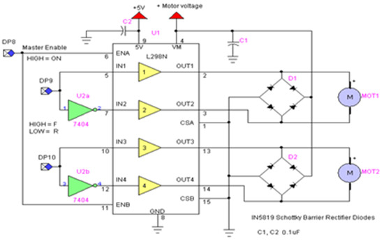
Figure 4.
Power module diagram.
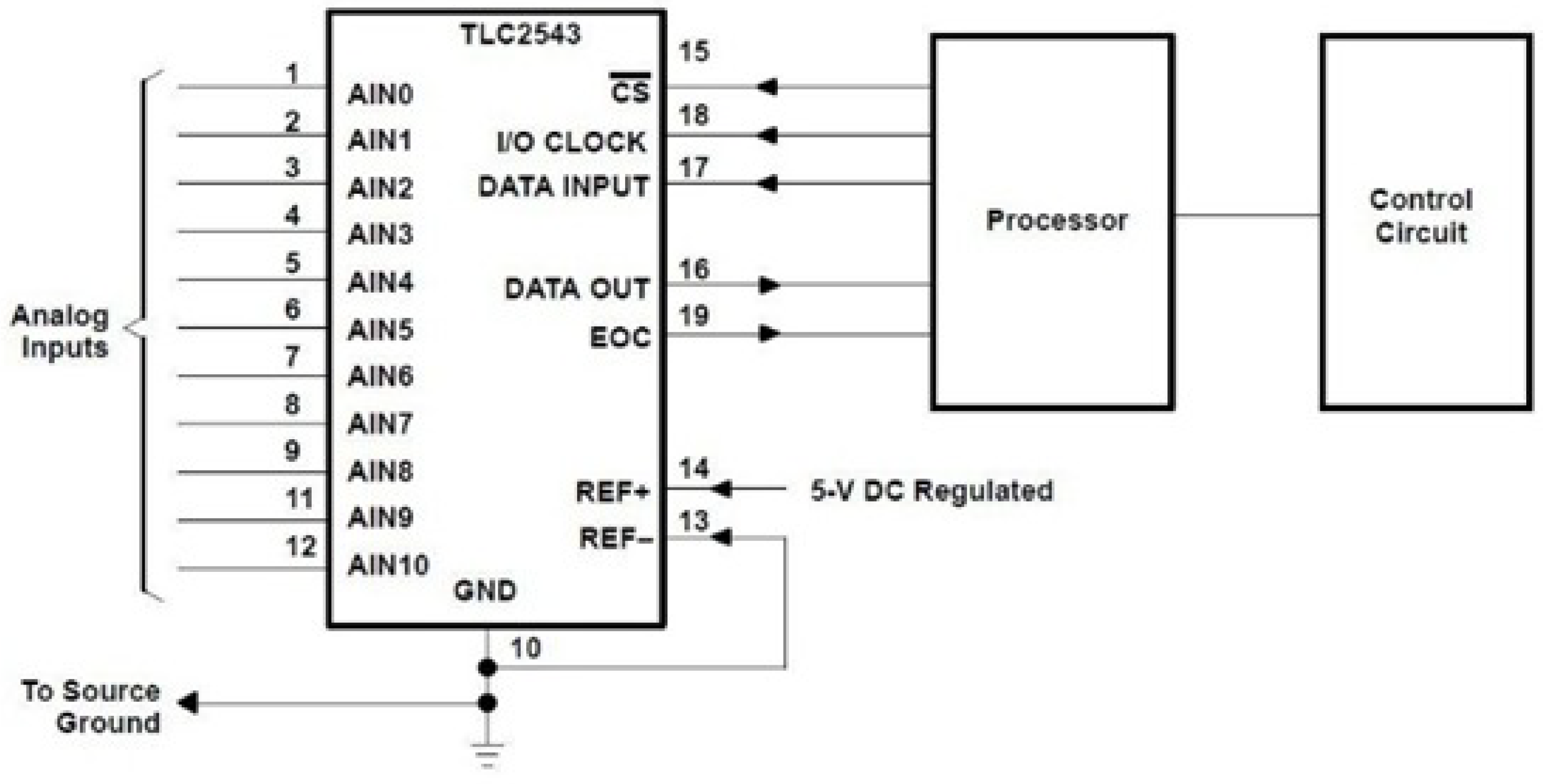
5.4. Analog Signal Conversion
To convert the analog signals from the potentiometers and deliver these data digitally to the processing hardware, the TLC2543 integrated circuit was selected [27]. This integrated circuit is an analog-to-digital converter (ADC) with 11 channels and a 12-bit resolution (see Figure 5).
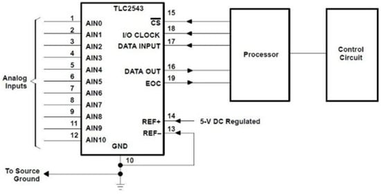
Figure 5.
Data collection circuit.
The TLC2543 ADC provides a significant advantage for this application due to its 12-bit resolution, enabling highly accurate digital representations of the analog voltages from the potentiometers. This high resolution is crucial, because it allows the system to capture small variations in the potentiometer values, which correspond to precise adjustments in the position of the solar tracker.
The ADC operates using the successive approximation register (SAR) method, which ensures a fast and accurate conversion process. This method is well-suited for systems like ours that require both speed and precision in real-time applications. The 12-bit resolution means that the voltage can be divided into 4096 discrete levels, making it possible to detect even slight changes in potentiometer values that are indicative of the solar tracker’s angular position.
The data collected from the ADC are sent to the microcontroller in digital format, enabling efficient processing and control of the solar tracking system. In future iterations of the project, additional channels of the ADC could be utilized to integrate more sensors, allowing the system to monitor other environmental factors, such as temperature and light intensity, enhancing the overall performance of the tracker.
The circuit diagram in Figure 5 illustrates the connection of the potentiometers to the ADC and the development board, providing a clear overview of the hardware used in the data acquisition process.
5.5. Characterization of Movements
After coupling each of the linear potentiometers to the output shaft of the geared motors, they were fed with a regulated voltage of 5 V, and data were collected to establish a linear relationship between the measured voltage in each potentiometer and the angular position in each of the degrees of freedom.
5.5.1. Solar Height (Tilt)
The characterization of the solar height was carried out using the ADC and the development board, relating the voltage of the potentiometer with the solar altitude measured in degrees (see Figure 6).
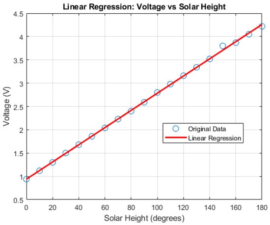
Figure 6.
Linearization of the results of the solar height linear potentiometer.
By performing a linear regression to determine the equation that governed the behavior of the potentiometer, the voltage was obtained as a function of degrees (Equation (13)).
where V is the measured voltage, is the solar height in degrees, and corresponds to the linearity coefficient.
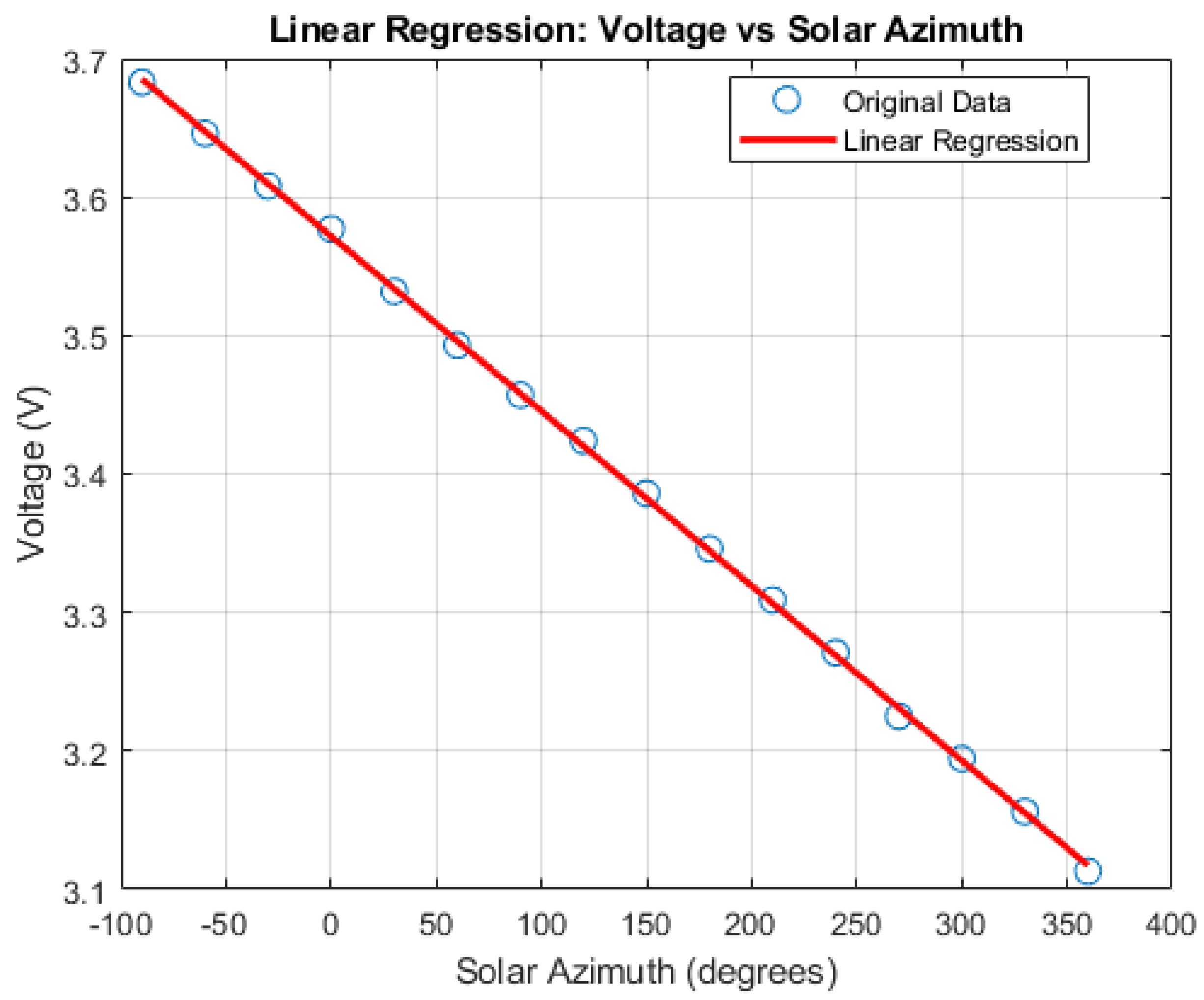
5.5.2. Azimuth (Orientation)
Similarly as for the potentiometer used in the solar height movement, its characterization was carried out through the ADC of the development board, comparing the sensed voltage with the solar azimuth in degrees (see Figure 7).
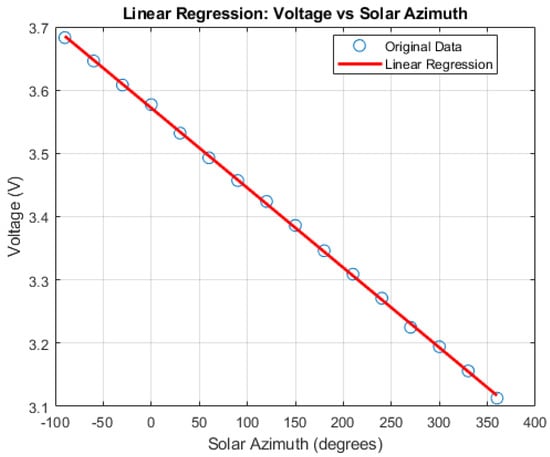
Figure 7.
Linearization of the results of the solar azimuth linear potentiometer.
Once these data had been recorded, an equation that identified the behavior of this mechanism was determined (Equation (14)).
where V corresponds to the measured voltage, is the solar azimuth in degrees, and is the linearity coefficient.
6. Results
6.1. Experimental Setup
For the experimental tests, the solar tracking system was equipped with an Upsolar UP-M250P photovoltaic (PV) panel. This panel was chosen for its reliable performance, and it consists of 60 photovoltaic cells made of polycrystalline silicon [28]. It was configured to operate with two degrees of freedom, to optimize the capture of incident solar radiation. The main technical specifications of the panel are summarized in Table 1.

Table 1.
Key specifications of the Upsolar UP-M250P module.
Data collection from the solar tracker was scheduled every 30 min. Two scalers were employed as measurement elements, strategically positioned on each of the turning movements of the system. These scalers enabled the visualization of the azimuth and solar height positions in degrees.
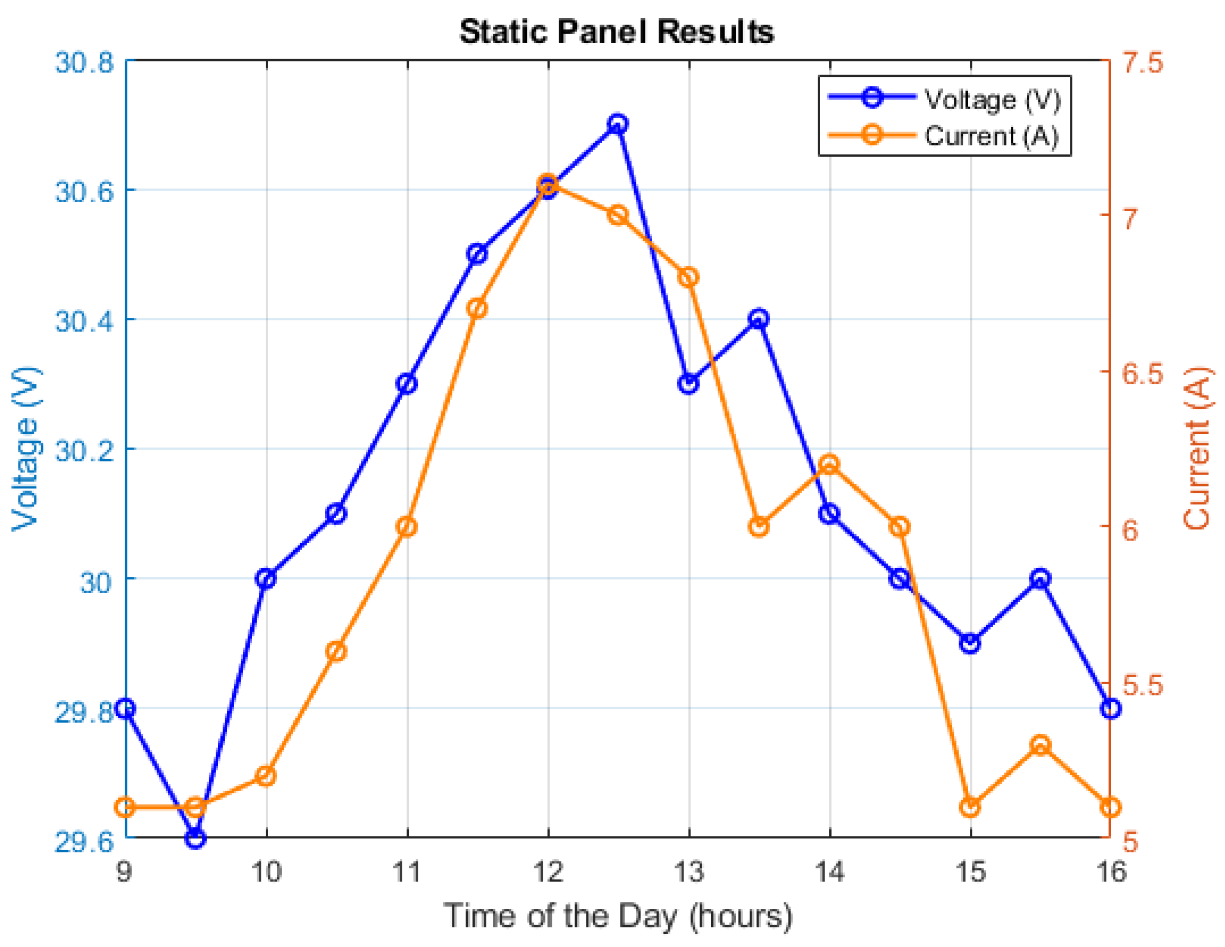
To evaluate the performance of the solar tracker, a comparative test was conducted between the static structure and the solar tracking system. The test took place from 7 to 11 November, between 9:00 a.m. and 4:00 p.m. on each day. The power generated was recorded at 30 min intervals and averaged over the five days to obtain more accurate results under direct sunlight. The results for the static panel are presented in Figure 8.
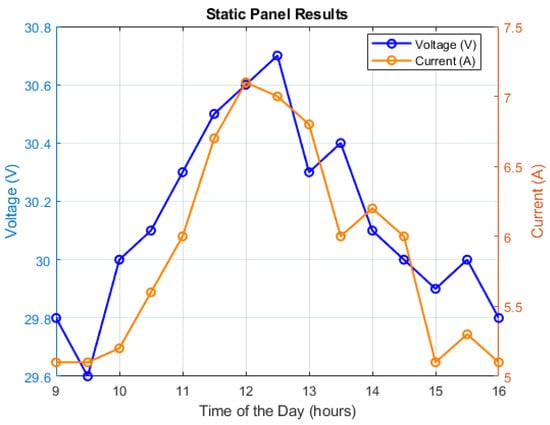
Figure 8.
Output current and voltage measured time functions for the static photovoltaic system.
The static panel recorded an average energy output of 177.62 kWh over the 7 h duration, with maximum efficiency peaks occurring during the midday hours. Conversely, a lower efficiency was observed in the morning and afternoon, likely due to suboptimal sun angles and partial shading effects.
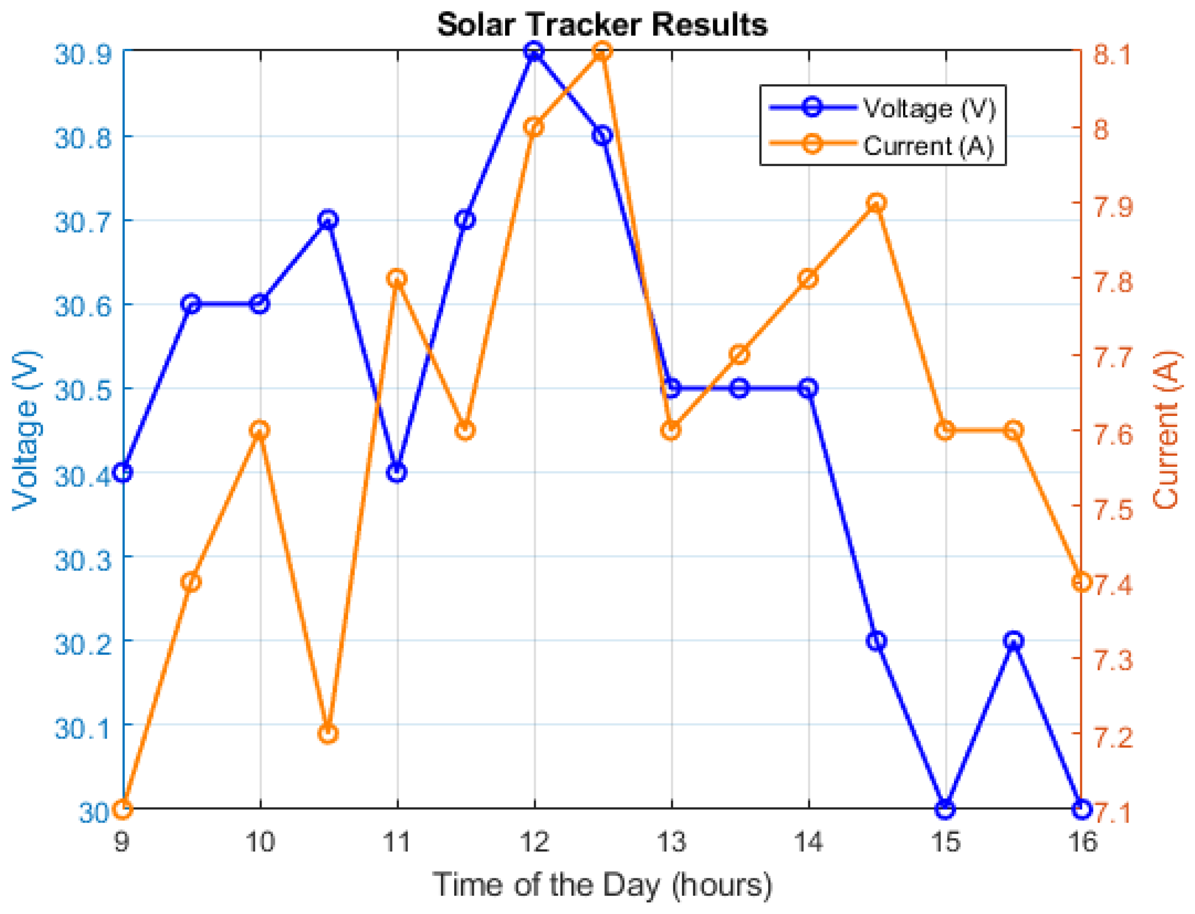
The results for the solar tracker are depicted in Figure 9.
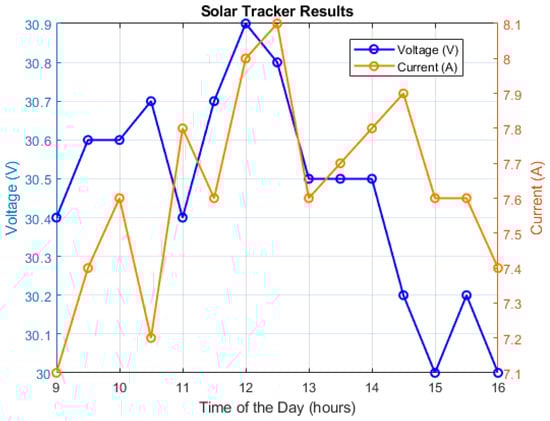
Figure 9.
Output current and voltage measured time functions for the solar tracking system.
The solar tracking system demonstrated an average energy output of 232.38 kWh throughout the same period. This increase in energy generation can be attributed to the ability of the solar tracker to maintain optimal alignment with the sun, allowing it to capture more solar radiation as the sun traversed across the sky.
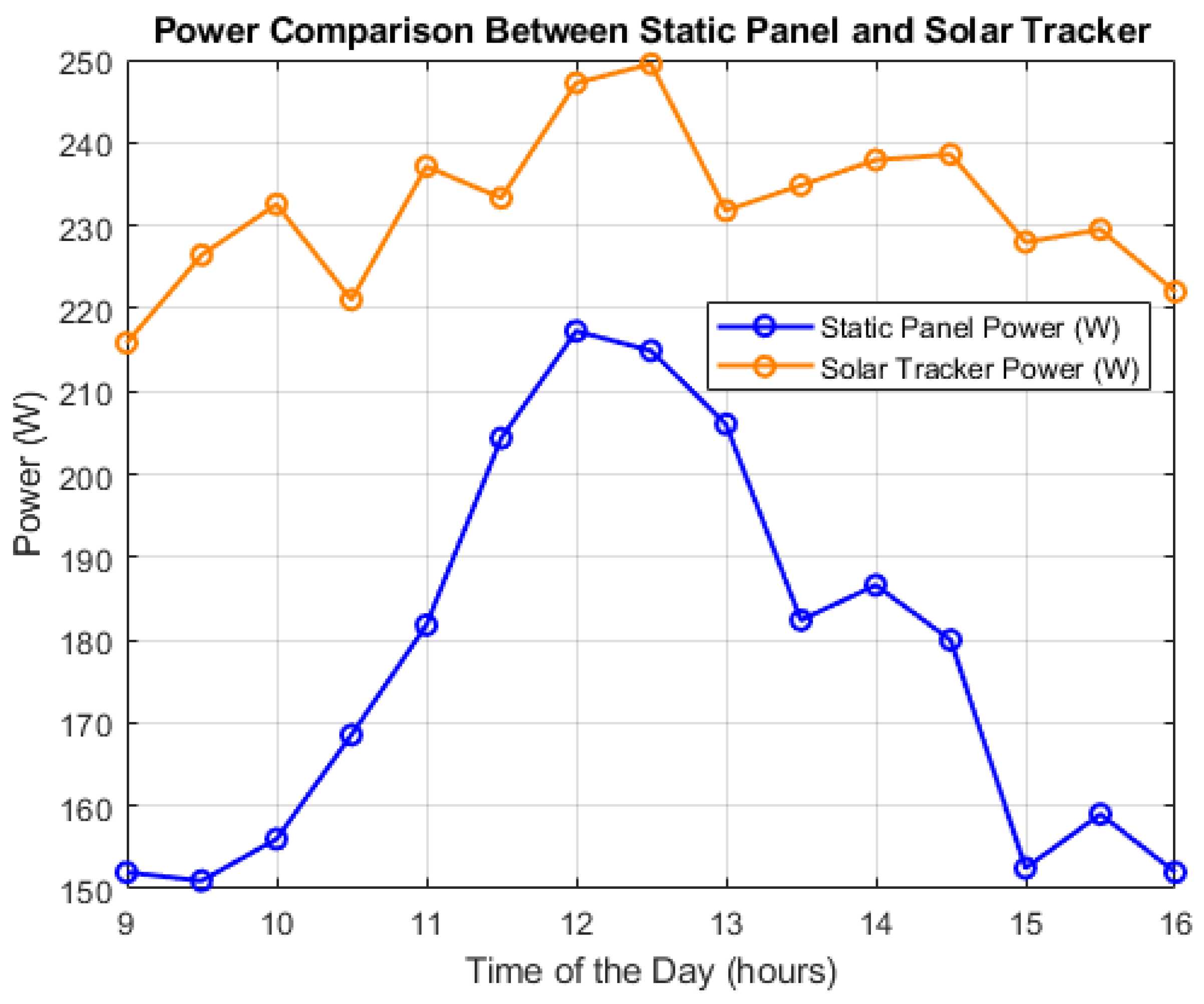
The instantaneous power calculations and their comparison with the static panel can be observed in Figure 10.

Figure 10.
Comparison of generation powers for monitoring and fixed systems.
From the analysis of the results, it was determined that the solar tracker achieved an average improvement of approximately 30.83% compared to the static panel. This calculation was based on data collected over an entire week, ensuring a reliable representation of the systems’ performance under varying solar radiation and weather conditions.
It is important to note that this percentage does not yet account for the energy consumption of the motors and the control board of the solar tracker, which is relatively low. Once this consumption is deducted, the net improvement is expected to remain significant, reinforcing the feasibility of the system. This analysis highlights that even when considering the tracker’s own energy use, its efficient design allows for a notable optimization in energy generation.
In particular, the low-cost design and reduced energy consumption of the system’s components make it a practical and scalable solution, especially in tropical regions with high solar incidence. This study underscores how mathematical modeling, control strategies, and optimization can maximize solar energy capture, without requiring prohibitive investments.
These data suggest that solar tracking systems, even when accounting for their internal consumption, provide a considerable increase in energy yield. This reinforces the importance of adaptive solar technologies as a key tool for maximizing the efficiency of photovoltaic installations under various climatic conditions.
6.2. Energy Consumption Analysis and Net Benefit
After analyzing the results and determining that the solar tracker achieved a 30.83% improvement in energy generation compared to the static panel, it was important to account for the energy consumption of the tracking system itself, in order to calculate the net improvement. The energy consumption of the various components of the solar tracker, including the control board, motors, and actuators, plays a crucial role in evaluating the overall benefit of the system.
6.2.1. Energy Consumption of the Control Module
The Intel Edison control module is the core of the tracking system, responsible for managing the tracking algorithm, controlling the motors, and communicating with other components of the system. The energy consumption of the control module was measured in two conditions: with and without Wi-Fi, as shown in Table 2.
Table 2.
Power consumption of the control module.
The average daily consumption of the control module, considering the system operating continuously for 24 h, was 44 Wh/day.
6.2.2. Energy Consumption of the Potentiometers
The potentiometers, used for measuring the solar altitude and azimuth, also consume energy, though their consumption is relatively low, as shown in Table 3.
Table 3.
Power consumption of the potentiometers.
The total consumption of the potentiometers was very low, amounting to approximately 0.0257 Wh/day.
6.2.3. Energy Consumption of the Relays and ADC Circuit
The relays and ADC circuit consumed 160 mA at 5.1 V, resulting in a power consumption of 816 mW.
6.2.4. Energy Consumption of the Actuators
The actuators controlling the movement of the solar tracker (azimuth and solar altitude) are the components that contribute the most to the energy consumption. The energy required for movement varies depending on the operating conditions of the motors, as shown in Table 4.
Table 4.
Power consumption of the actuators.
Since the solar tracker operates in automatic mode, the actuators move the panel by a specific distance each day, as shown in Table 5.
Table 5.
Operation time per movement.
The daily energy consumption of each actuator was as follows:
- -
- Azimuth: 2.5 Wh/day
- -
- Solar Altitude: 0.26 Wh/day.
6.2.5. Energy Consumption During Motor Starts
In addition to continuous operation, the motors experience starts that consume higher amounts of energy at specific moments. During each start, the motors reached a current peak of 2.5 A at 20.2 V for approximately 0.2 s. The total energy consumption per start was approximately 50.5 W for 11.2 s, which equals 0.16 Wh/day.
6.2.6. Total Energy Consumption of the Tracking System
Summing up the consumption of all components, the total daily energy consumption of the tracking system was as follows in Table 6.
Table 6.
Total energy consumption of the system.
6.2.7. Net Energy Benefit
Finally, to calculate the net energy benefit of the tracking system, we subtracted the system’s energy consumption from the energy generated by the tracker:
- -
- Energy generated by the solar tracker: 1626.66 Wh/day
- -
- Energy generated by the static panel: 1243.34 Wh/day
- -
- Gross improvement: 1626.66 Wh/day − 1243.34 Wh/day = 383.32 Wh/day
Now, subtracting the consumption of the system:
- -
- Net energy benefit: 383.32 Wh/day − 46.92 Wh/day = 336.40 Wh/day
Therefore, the percentage of net improvement was
7. Conclusions
The implementation of solar positioning equations in the design of an experimental solar tracker with two degrees of freedom was proven to be an effective strategy for maximizing solar energy capture. This system, designed to mobilize an Upsolar 250 photovoltaic panel, not only optimizes the panel’s orientation to ensure its perpendicularity to the sun’s rays throughout the day but also establishes a practical and efficient approach for improving energy efficiency in real-world applications.
The results obtained revealed a significant 27% increase in energy efficiency compared to static systems. This increase is clear evidence of the advantages of automated solar tracking, particularly in regions with high solar exposure, such as the tropics. Additionally, the system demonstrates a cost-effective and viable solution for maximizing the utilization of solar resources in small- and medium-scale photovoltaic applications.
Beyond the immediate technical impact, the development of this solar tracker has important implications for research and development in the field of renewable energy. This project not only contributes to improving photovoltaic performance in tropical climates such as Bucaramanga but also paves the way for future studies that could explore the integration of advanced technologies, such as the use of artificial intelligence to optimize the tracker’s movement in real time or the development of lighter and more durable materials for its construction.
Additionally, the results of this work underscore the need to consider the adaptability of tracking systems to different climatic and geographical contexts. For example, future projects could investigate how the implementation of tracking systems could be adjusted to areas with extreme weather conditions, distinct seasons, or more variable solar radiation levels.
From an environmental perspective, the insights gained in this research are relevant for advancing the sustainable use of renewable energy. Improving the efficiency of photovoltaic systems directly contributes to reducing the carbon footprint associated with electricity generation and strengthens the economic feasibility of solar energy in rural and urban communities.
This project not only validated the effectiveness of solar tracking systems as a tool for maximizing photovoltaic panel efficiency but also established a solid foundation for future research. The incorporation of technological innovations, the evaluation of new materials, and the customization of these systems for different environments will enable continued progress toward a more sustainable and efficient energy future. This work, therefore, represents an important step toward the development of practical solutions to address the energy challenges of the 21st century.
Author Contributions
Conceptualization, J.M.B.-S. and E.I.T.-R.; methodology, J.M.B.-S.; software, J.M.B.-S.; validation, J.M.B.-S. and E.I.T.-R.; formal analysis, J.M.B.-S.; investigation, J.M.B.-S.; resources, J.M.B.-S.; data curation, J.M.B.-S.; writing—original draft preparation, J.M.B.-S.; writing—review and editing, J.M.B.-S. and E.I.T.-R.; visualization, J.M.B.-S.; supervision, J.M.B.-S.; project administration, J.M.B.-S.; funding acquisition, E.I.T.-R. All authors have read and agreed to the published version of the manuscript.
Funding
This research was partially funded by the University of Guanajuato. The APC was funded by the authors.
Institutional Review Board Statement
Not applicable.
Informed Consent Statement
Not applicable.
Data Availability Statement
Data are contained within the article.
Conflicts of Interest
The authors declare no conflict of interest.
References
- de Souza Lins, F.; da Silva, V.A.; de Alencar Nääs, I.; da Silva Lima, N.D.; da Silva, M.C. The efficacy of a dual-axis solar tracking device in tropical climate. Res. Soc. Dev. 2020, 9, e96371102. [Google Scholar]
- Kanyarusoke, K.E.; Gryzagoridis, J.; Oliver, G. Are solar tracking technologies feasible for domestic applications in rural tropical Africa? J. Energy S. Afr. 2015, 26, 86–95. [Google Scholar]
- Kuttybay, N.; Mekhilef, S.; Koshkarbay, N.; Saymbetov, A.; Nurgaliyev, M.; Dosymbetova, G.; Bolatbek, A. Assessment of solar tracking systems: A comprehensive review. Sustain. Energy Technol. Assess. 2024, 68, 103879. [Google Scholar] [CrossRef]
- Fazlizan, A.; Abdulmula, A.; Amran, A.N.; Lim, C.H.; Sopian, K. Performance evaluation of maximum light detection solar tracking system in the tropics. J. Mech. Sci. Technol. 2019, 33, 1391–1397. [Google Scholar] [CrossRef]
- Carpino, C.; Austin, M.C.; Chung-Camargo, K.; Mora, D.; Arcuri, N. Building performance modelling approaches for a detached vertical green trellis: A case study in a tropical climate. Sustain. Energy Technol. Assess. 2024, 71, 103972. [Google Scholar]
- Zsiborács, H.; Bai, A.; Popp, J.; Gabnai, Z.; Pályi, B.; Farkas, I.; Hegedűsné Baranyai, N.; Veszelka, M.; Zentkó, L.; Pintér, G. Change of real and simulated energy production of certain photovoltaic technologies in relation to orientation, tilt angle and dual-axis sun-tracking. A case study in Hungary. Sustainability 2018, 10, 1394. [Google Scholar] [CrossRef]
- Awasthi, A.; Shukla, A.K.; SR, M.M.; Dondariya, C.; Shukla, K.N.; Porwal, D.; Richhariya, G. Review on sun tracking technology in solar PV system. Energy Rep. 2020, 6, 392–405. [Google Scholar] [CrossRef]
- Fuentes-Morales, R.F.; Diaz-Ponce, A.; Peña-Cruz, M.I.; Rodrigo, P.M.; Valentín-Coronado, L.M.; Martell-Chavez, F.; Pineda-Arellano, C.A. Control algorithms applied to active solar tracking systems: A review. Sol. Energy 2020, 212, 203–219. [Google Scholar]
- Wang, J.M.; Lu, C.L. Design and implementation of a sun tracker with a dual-axis single motor for an optical sensor-based photovoltaic system. Sensors 2013, 13, 3157–3168. [Google Scholar] [CrossRef]
- Salgado-Conrado, L. A review on sun position sensors used in solar applications. Renew. Sustain. Energy Rev. 2018, 82, 2128–2146. [Google Scholar]
- Al-Othman, A.; Younes, T.; Al-Adwan, I.; Al Khawaldah, M.; Alauthman, H.; Alkhedher, M.; Ramadan, M. An experimental study on hybrid control of a solar tracking system to maximize energy harvesting in Jordan. Sol. Energy 2023, 263, 111931. [Google Scholar] [CrossRef]
- Mamodiya, U.; Tiwari, N. Dual-axis solar tracking system with different control strategies for improved energy efficiency. Comput. Electr. Eng. 2023, 111, 108920. [Google Scholar] [CrossRef]
- Wang, J.; Zhong, H.; Lai, X.; Xia, Q.; Wang, Y.; Kang, C. Exploring key weather factors from analytical modeling toward improved solar power forecasting. IEEE Trans. Smart Grid 2017, 10, 1417–1427. [Google Scholar] [CrossRef]
- Chowdhury, M.E.; Khandakar, A.; Hossain, B.; Abouhasera, R. A low-cost closed-loop solar tracking system based on the sun position algorithm. J. Sens. 2019, 2019, 3681031. [Google Scholar]
- Bouzakri, H.; Abbou, A. Mono-axial solar tracker with equatorial mount, for an improved model of a photovoltaic panel. Int. J. Renew. Energy Res. (IJRER) 2020, 10, 578–590. [Google Scholar]
- Ju, X.; Xu, C.; Hu, Y.; Han, X.; Wei, G.; Du, X. A review on the development of photovoltaic/concentrated solar power (PV-CSP) hybrid systems. Sol. Energy Mater. Sol. Cells 2017, 161, 305–327. [Google Scholar]
- Mamodiya, U.; Tiwari, N. Design and Implementation of Hardware-Implemented Dual-Axis Solar Tracking System for Enhanced Energy Efficiency. Eng. Proc. 2023, 59, 122. [Google Scholar] [CrossRef]
- Yao, Y.; Hu, Y.; Gao, S.; Yang, G.; Du, J. A multipurpose dual-axis solar tracker with two tracking strategies. Renew. Energy 2014, 72, 88–98. [Google Scholar] [CrossRef]
- Catota Sánchez, A.V.; Simbaña Simbaña, J.E. Diseño de un Colector Térmico Mediante Concentración Parabólica de Seguimiento Solar en dos Ejes. Bachelor’s Thesis, Universidad Politécnica Salesiana, Quito, Ecuador, 2020. [Google Scholar]
- Si, Z.; Yang, M.; Yu, Y.; Ding, T. Photovoltaic power forecast based on satellite images considering effects of solar position. Appl. Energy 2021, 302, 117514. [Google Scholar]
- Kumar, K.; Varshney, L.; Ambikapathy, A.; Mittal, V.; Prakash, S.; Chandra, P.; Khan, N. Soft computing and IoT based solar tracker. Int. J. Power Electron. Drive Syst. 2021, 12, 1880. [Google Scholar] [CrossRef]
- Hassan, Q.; Abbas, M.K.; Abdulateef, A.M.; Abdulateef, J.; Mohamad, A. Assessment of the potential solar energy with the models for optimum tilt angles of maximum solar irradiance for Iraq. Case Stud. Chem. Environ. Eng. 2021, 4, 100140. [Google Scholar] [CrossRef]
- Colak Gunes, N.; Oner, F. Evaluating the Impact of Solar Energy Systems on Exergy Efficiency and Carbon Footprint in Extra Virgin Organic Olive Oil Production. SSRN 4666159. 2023. Available online: https://ssrn.com/abstract=4666159 (accessed on 12 October 2024). [CrossRef]
- Neeley, W. Design and Development of a High-Performance Quadrotor Control Architecture Based on Feedback Linearization. 2016. Available online: https://digitalrepository.unm.edu/ece_etds/190 (accessed on 8 October 2024).
- Python Software Foundation. Python: Python Releases for Windows. 2021. Available online: https://www.python.org/downloads/windows/ (accessed on 10 September 2024).
- Azhari; Nasution, T.I.; Azis, P.F.A. MPU-6050 Wheeled Robot Controlled by Hand Gesture Using L298N Driver Based on Arduino. In J. Phys. Conf. Ser.; 2023; Volume 2421, p. 012022. [Google Scholar]
- Niu, Y.; Wang, H.; Abdullayevdep-t, V.; Al_Barazanchi, I.I. System design and implementation of an IoT electronic pulse sphygmomanometer. Babylon. J. Internet Things 2024, 2024, 1–9. [Google Scholar] [CrossRef]
- Upsolar. UP-M250-270P. 2024. Available online: https://es.enfsolar.com/pv/panel-datasheet/crystalline/42665 (accessed on 28 November 2024).


Disclaimer/Publisher’s Note: The statements, opinions and data contained in all publications are solely those of the individual author(s) and contributor(s) and not of MDPI and/or the editor(s). MDPI and/or the editor(s) disclaim responsibility for any injury to people or property resulting from any ideas, methods, instructions or products referred to in the content. |
© 2025 by the authors. Licensee MDPI, Basel, Switzerland. This article is an open access article distributed under the terms and conditions of the Creative Commons Attribution (CC BY) license (https://creativecommons.org/licenses/by/4.0/).