
Development of an Environmentally Friendly Steel Structural Framework: Evaluation of Bending Stiffness and Yield Bending Moment of Cross-Laminated Timber Slab–H-Shaped Steel Composite Beams for Component Reuse


Abstract
:
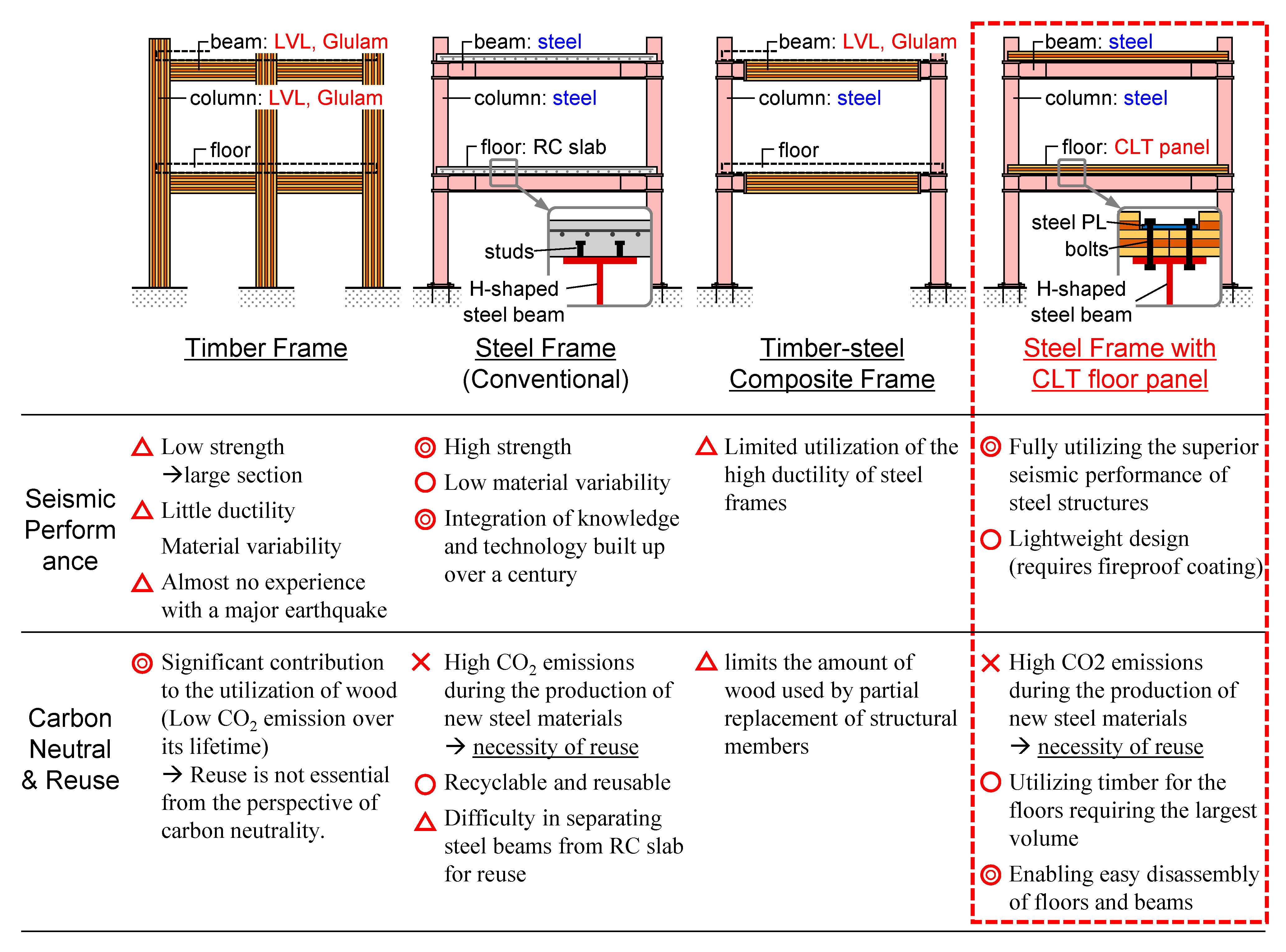
1. Introduction
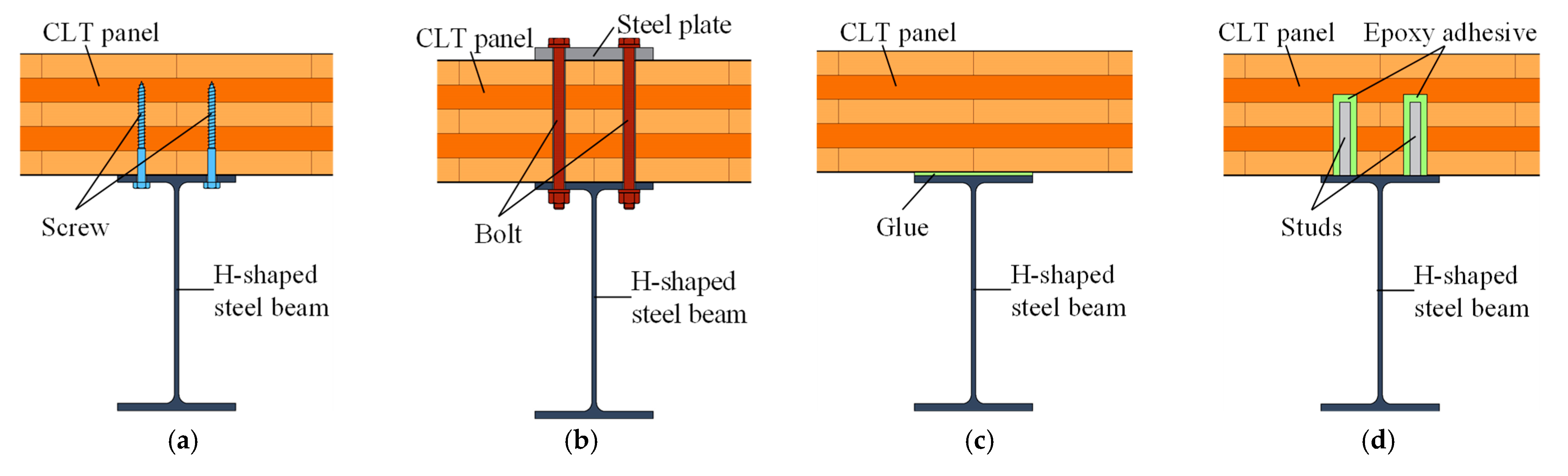
2. Double-Shear Tests of CLT–Steel Plate Friction Joints Using High-Strength Bolts
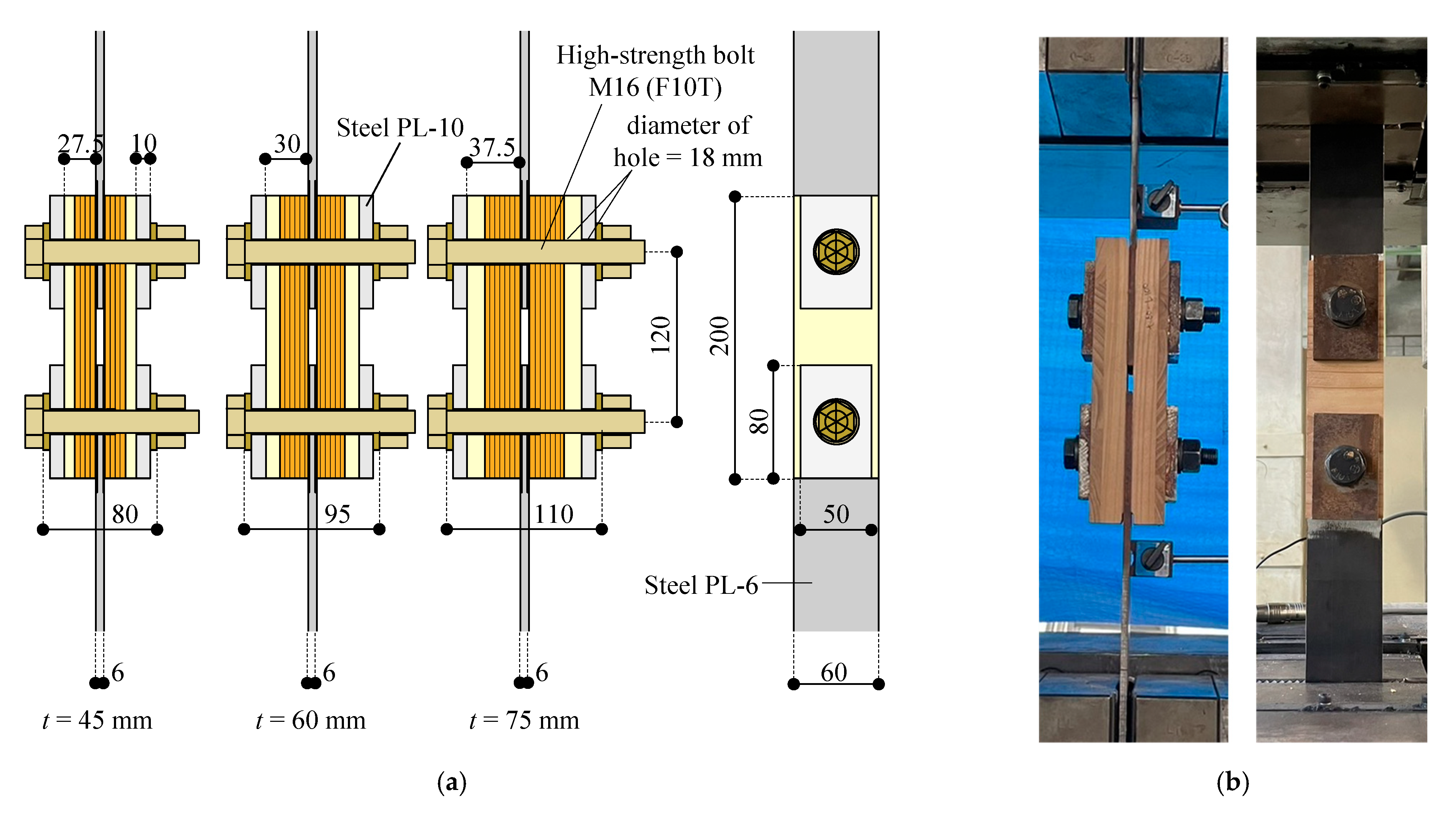
2.1. Test Setup and Test Parameters
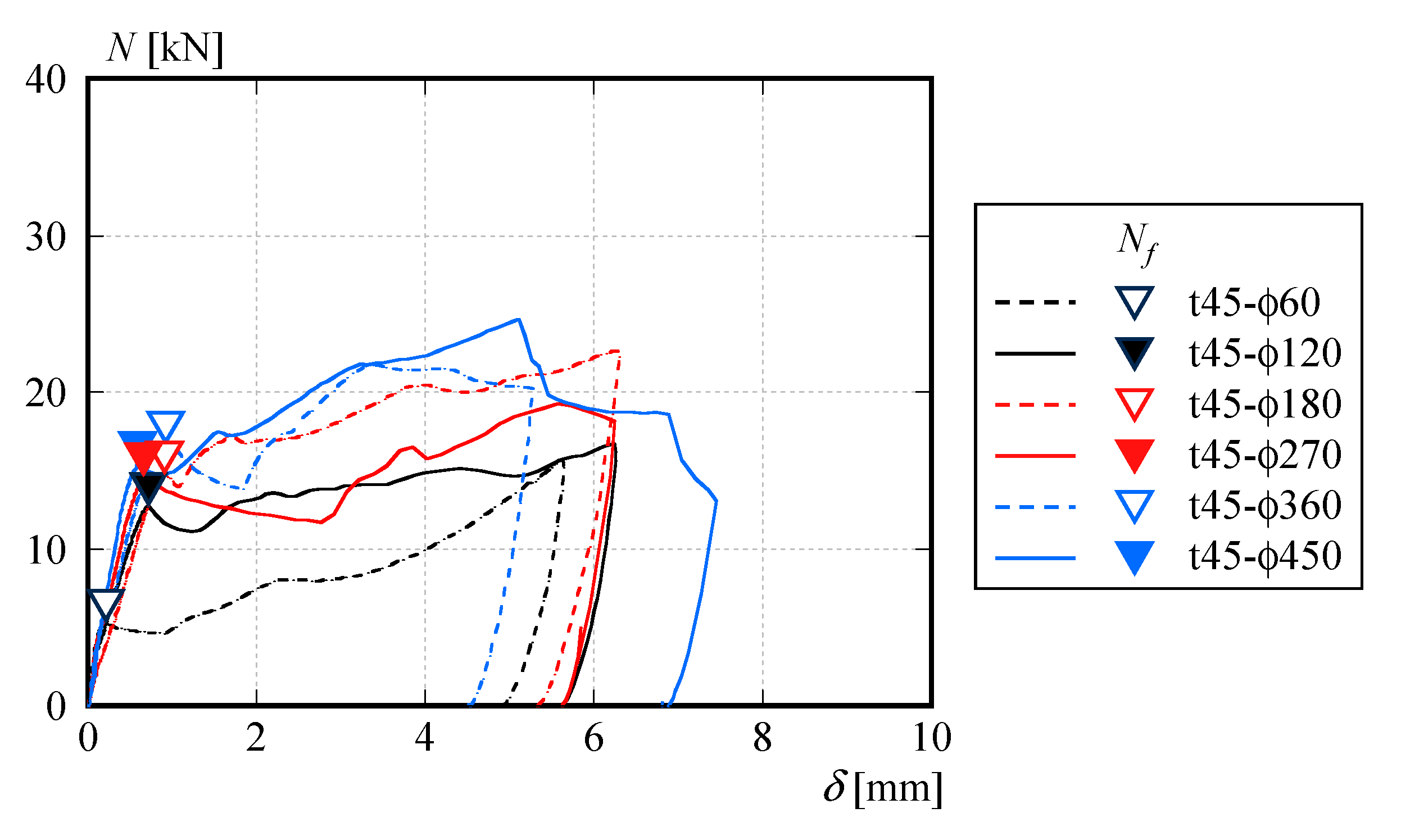
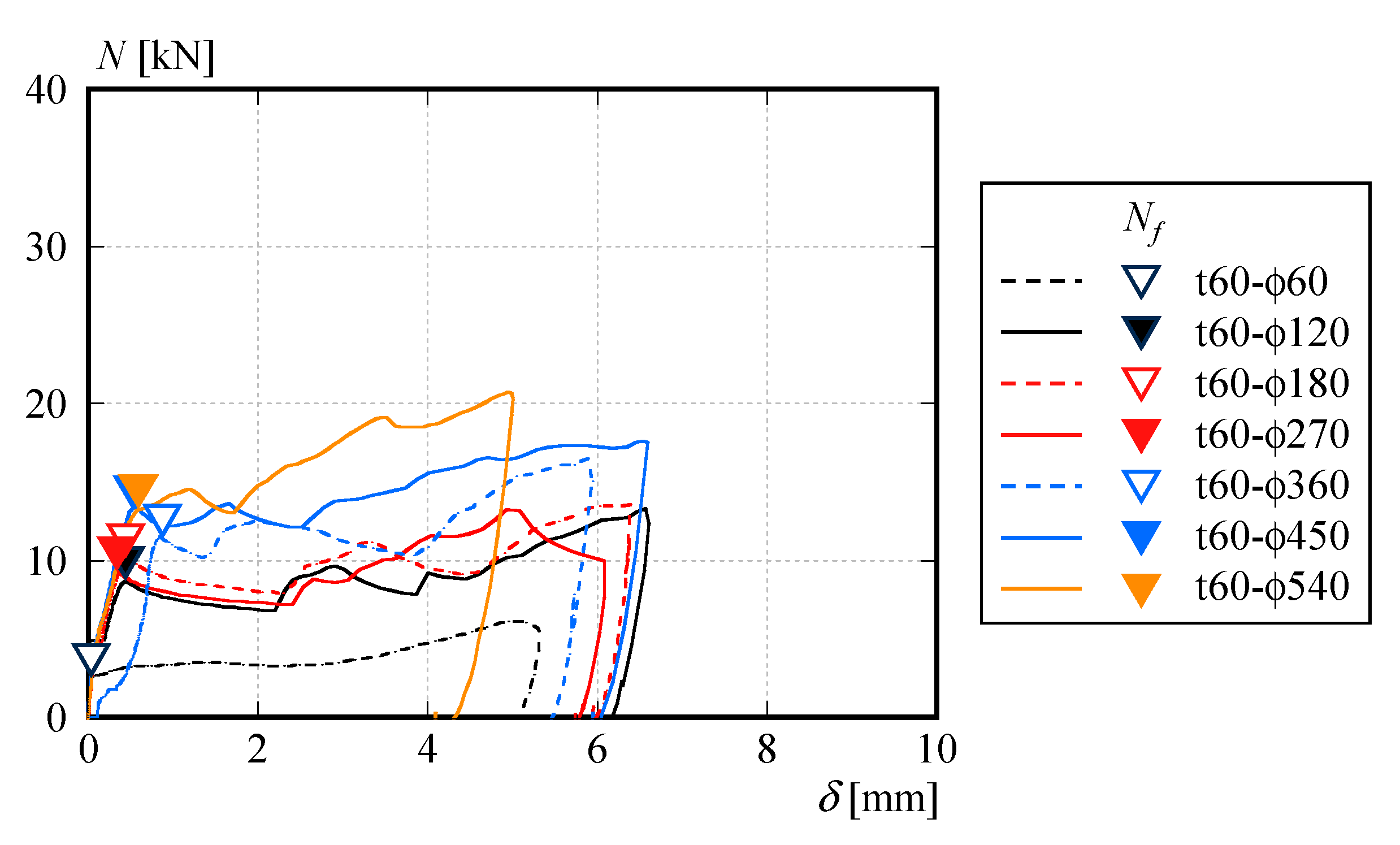
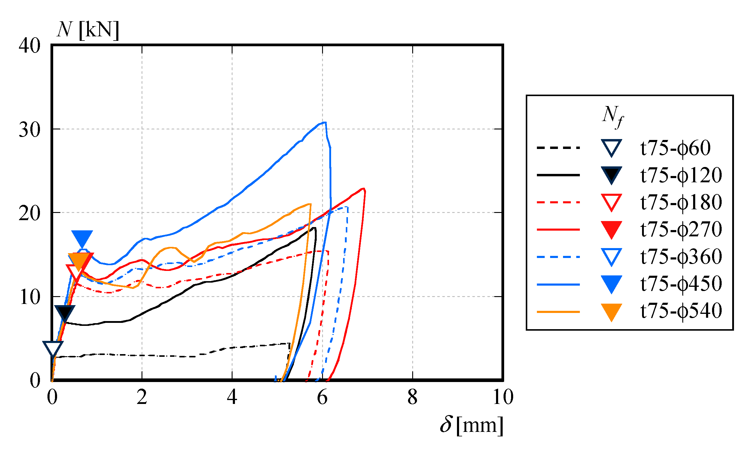
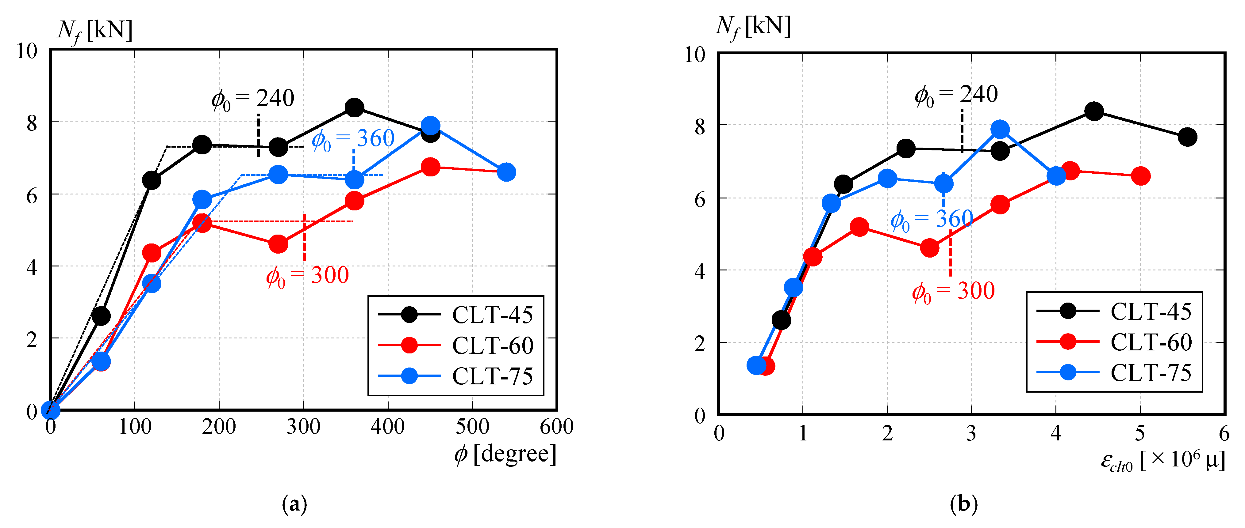
2.2. Static Friction Force with Respect to Bolt Tightening Angle
3. Four-Point Bending Test of CLT-Panel—H-Shaped-Steel Composite Beam
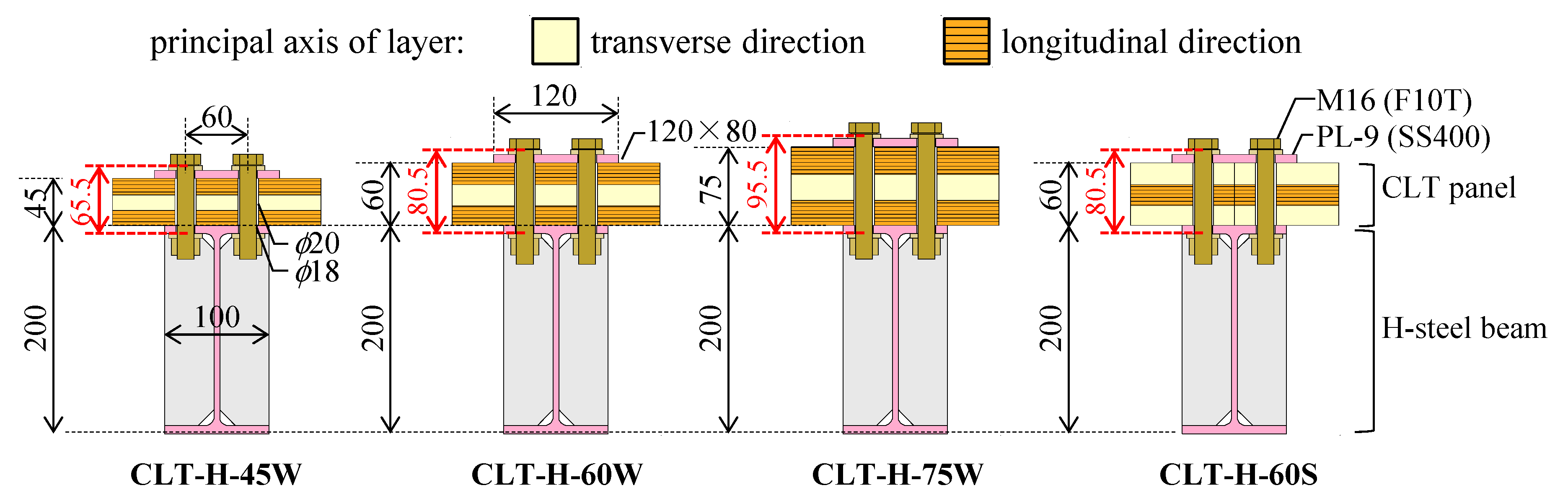
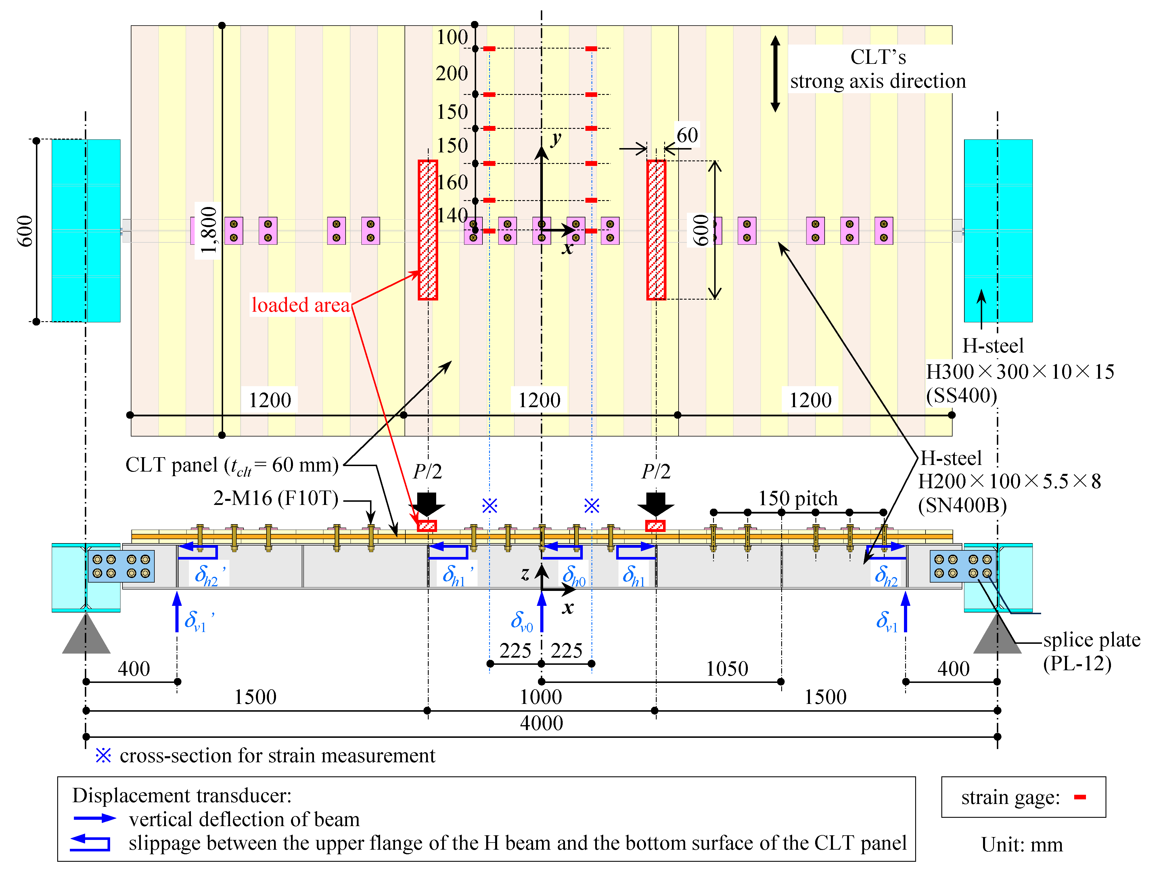
3.1. Specimen Design
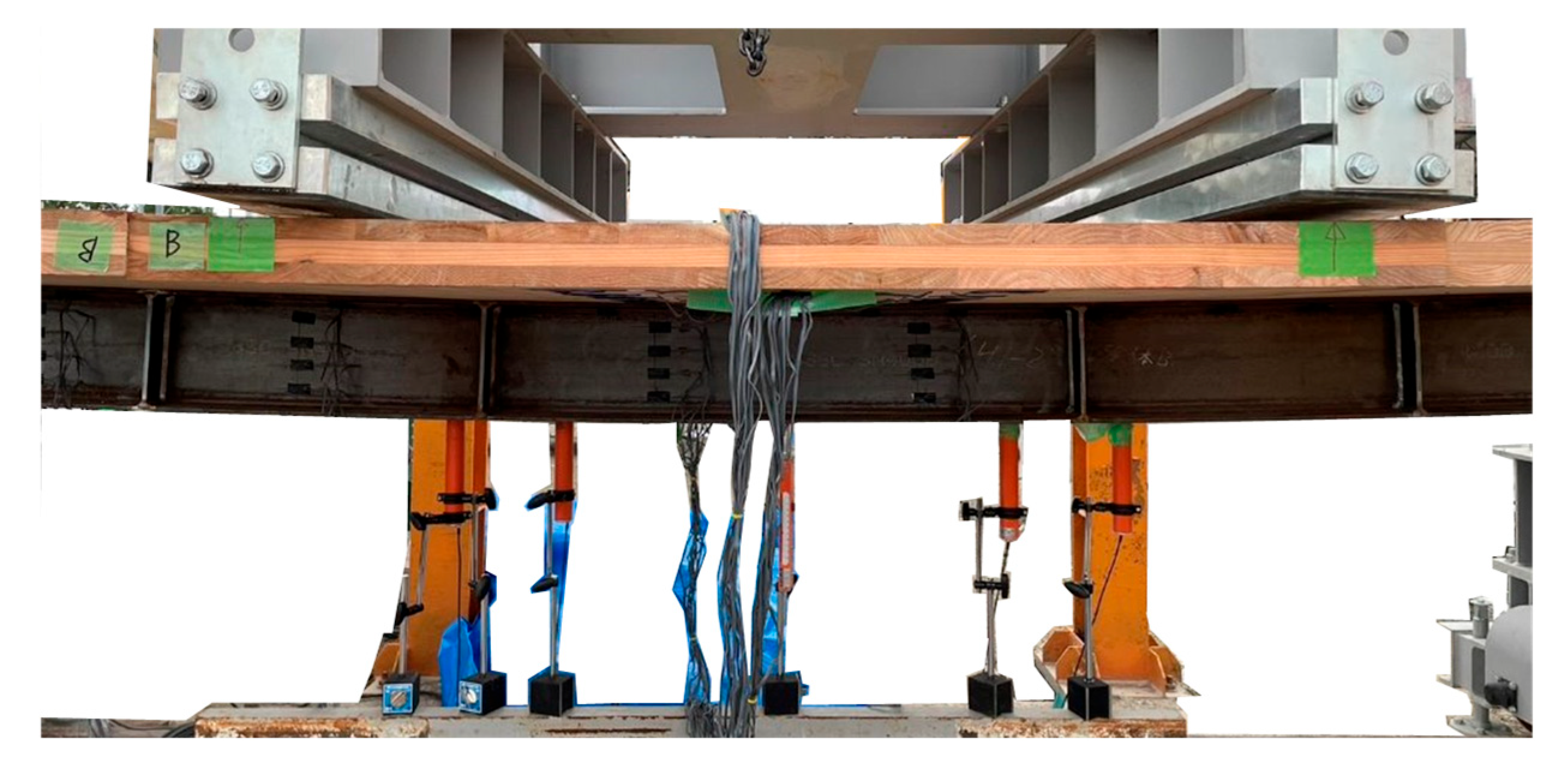
3.2. Test Setup and Test Parameters
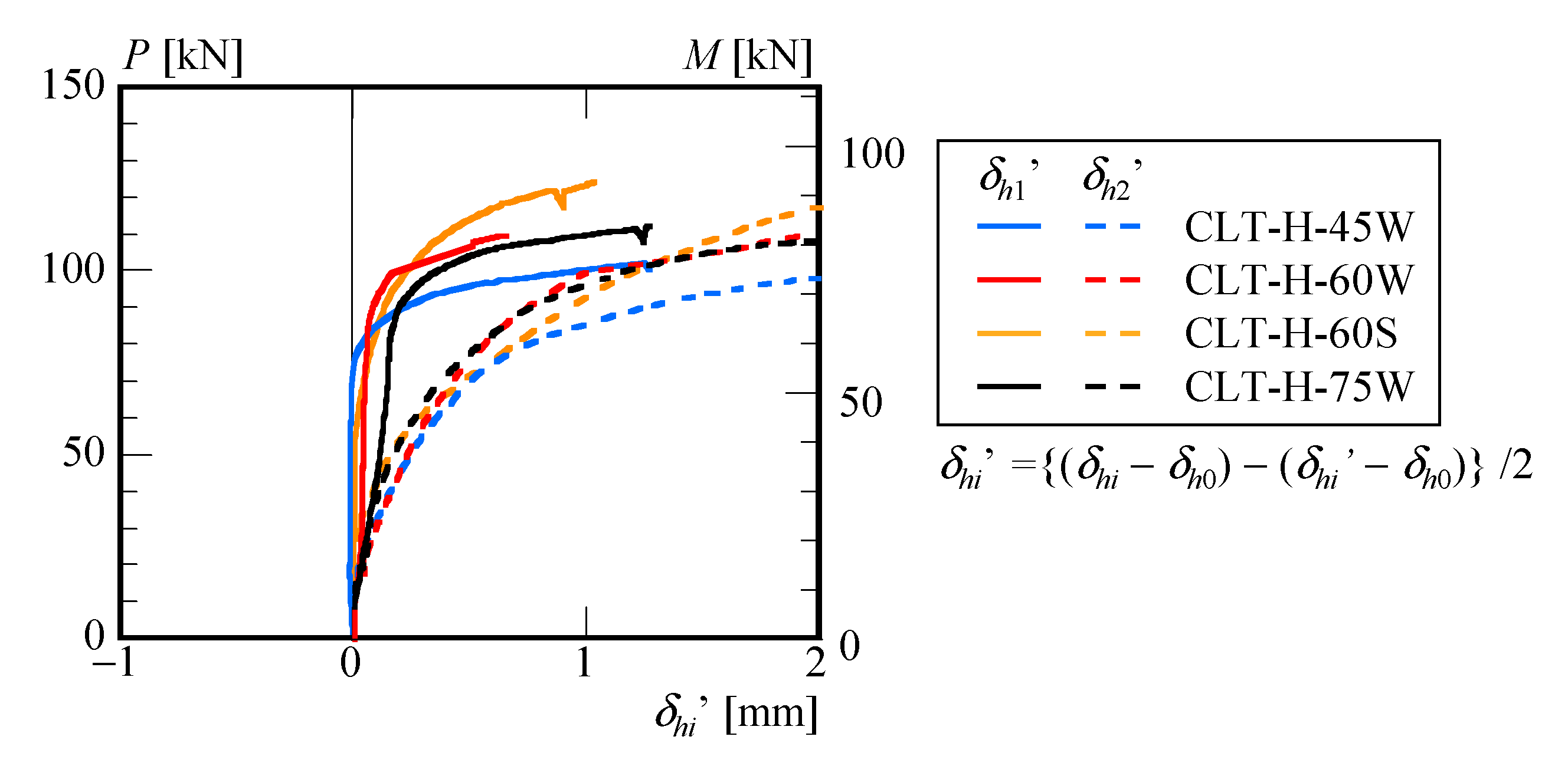
3.3. Test Results of Four-Point Bending Test
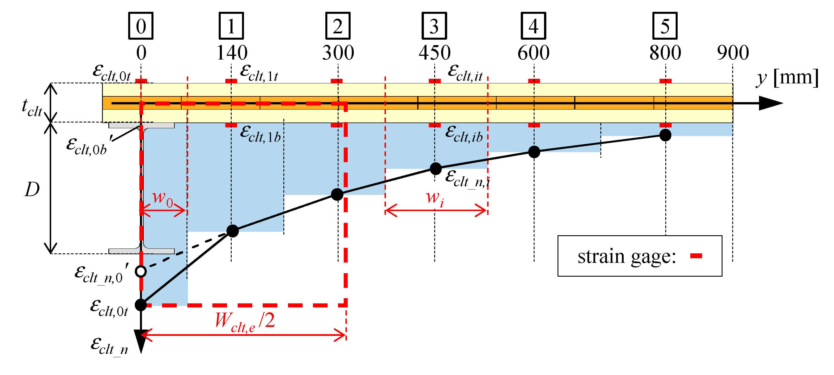
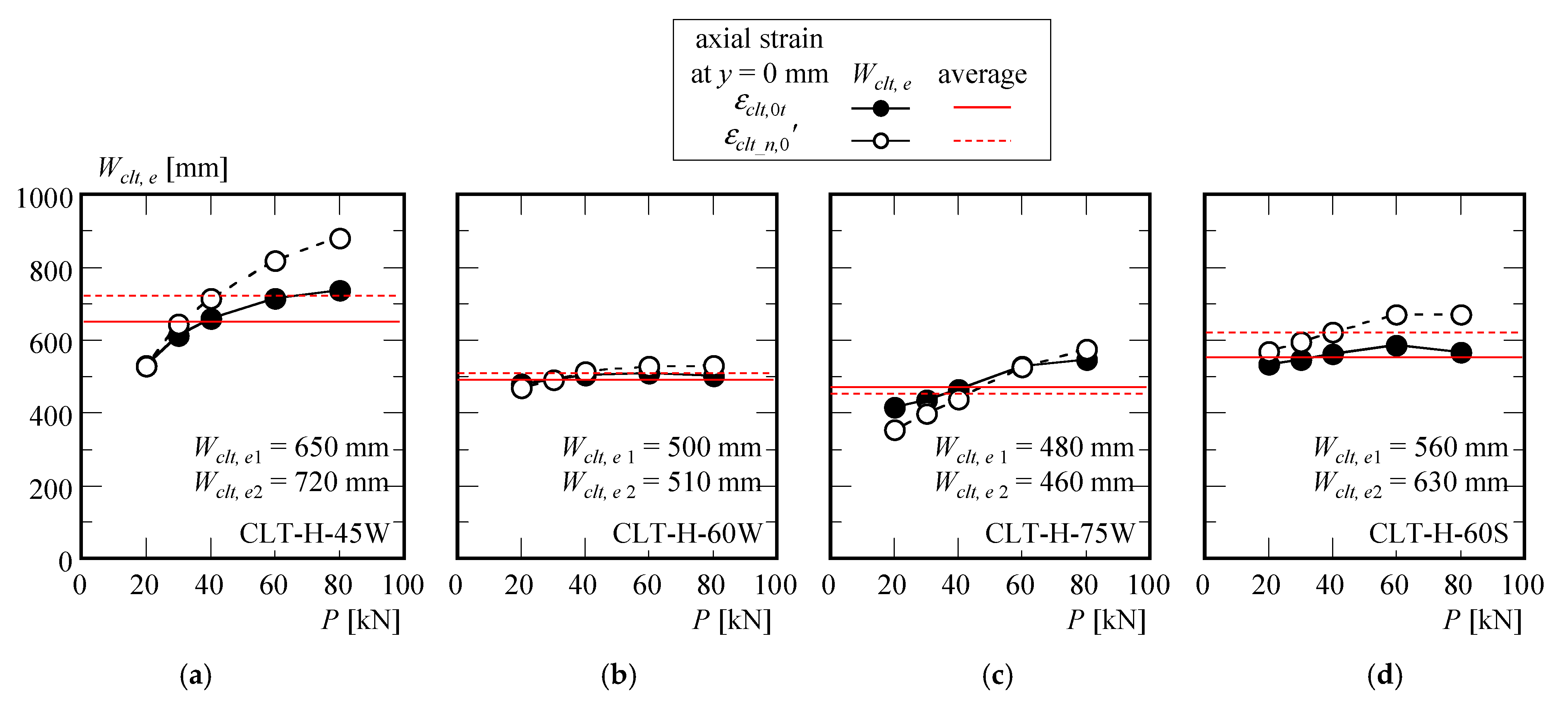
3.4. Effective CLT Slab Width
3.5. Prediction of Composite Stiffness and Strength
4. Conclusions
- (1)
- From the results of the double-shear tests conducted on CLT panels and steel plates connected using high-strength bolt friction joints, it was observed that when using a 50 mm × 80 mm × 10 mm steel washer, the static friction force Nf was approximately 5 kN when the axial force causing bearing yield of the CLT panel was applied to the bolt.
- (2)
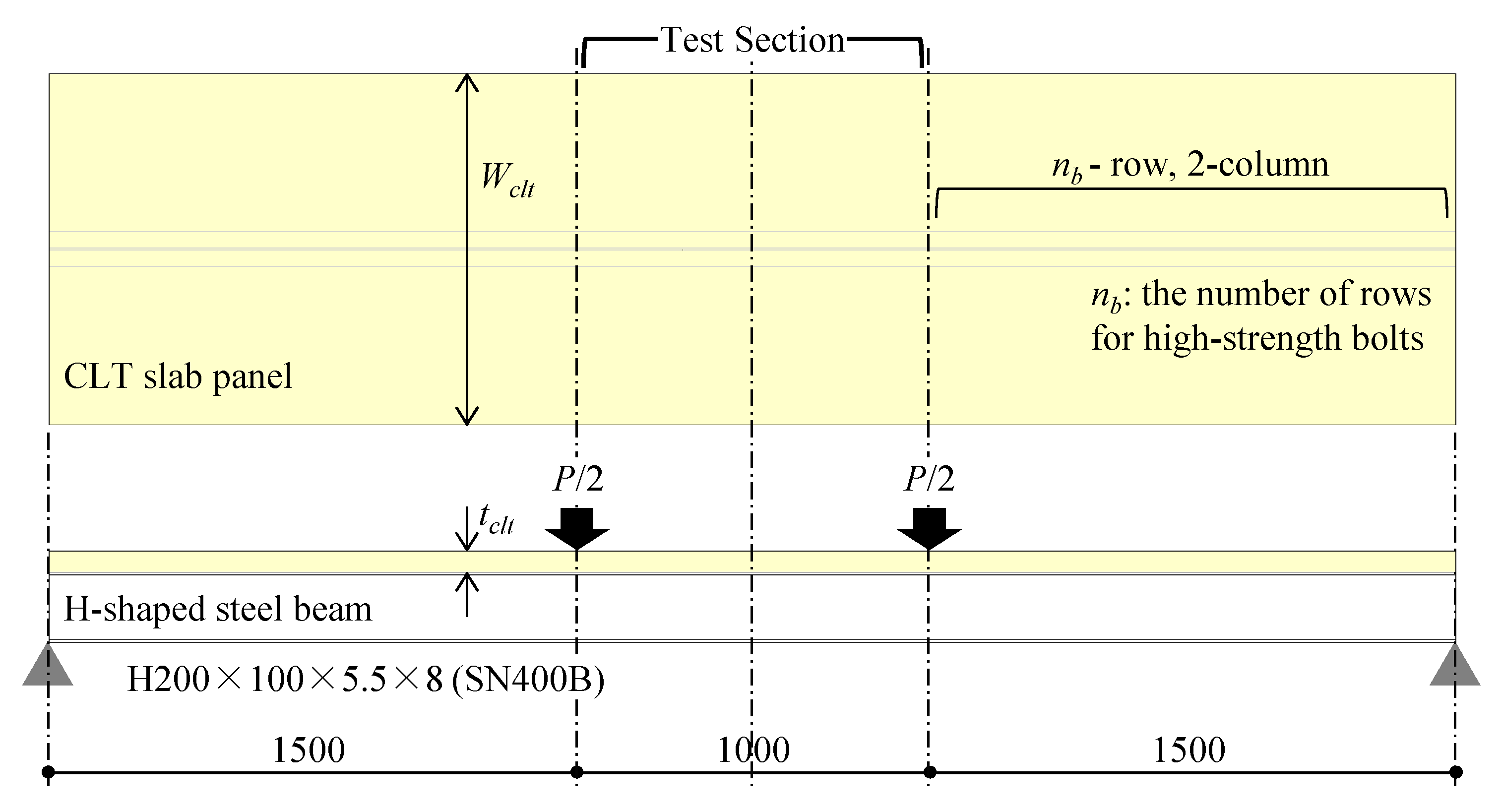
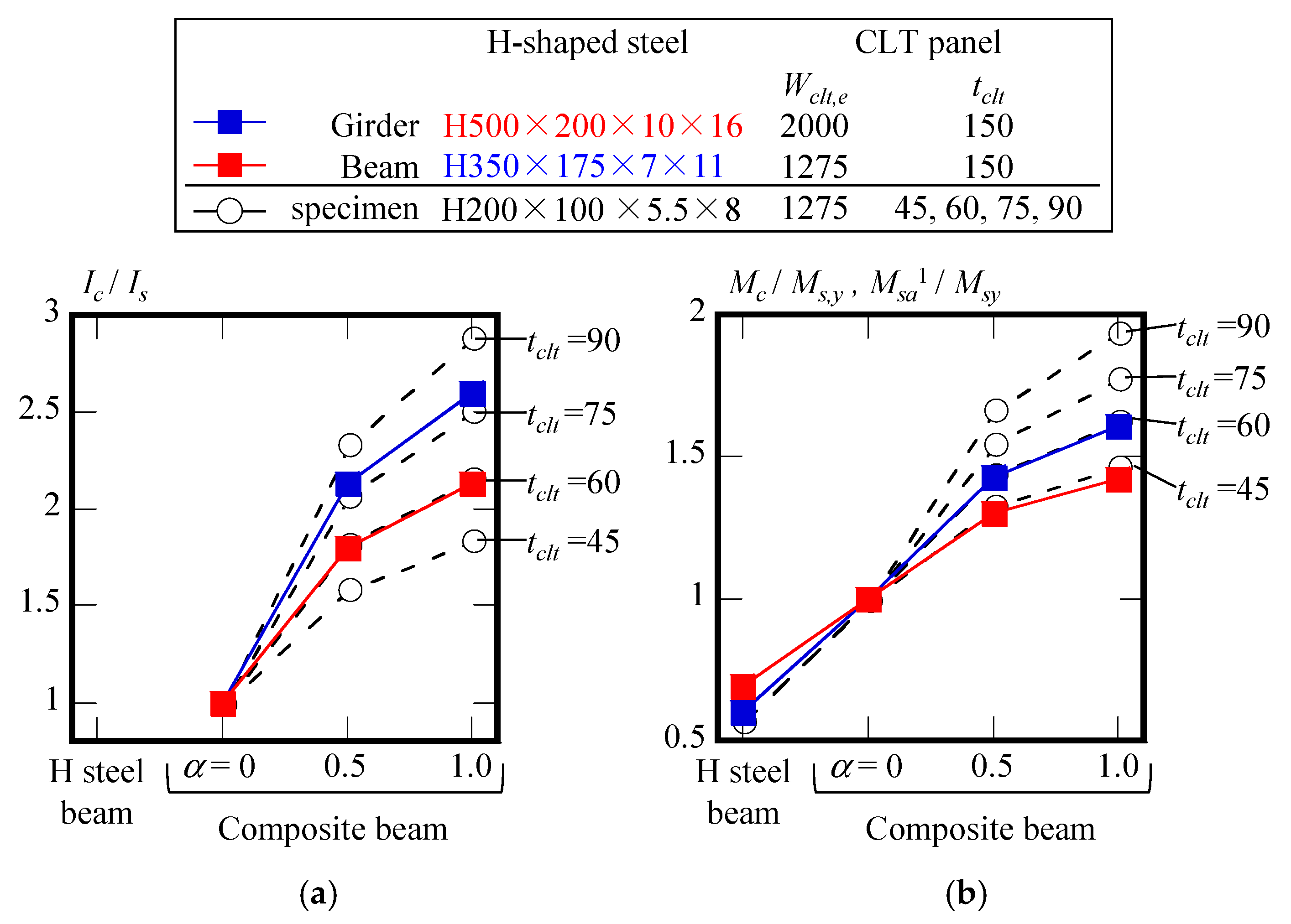
- It was confirmed through four-point bending tests that when CLT floor panels with thicknesses of tclt = 45, 60, and 75 mm were fixed to an H-shaped steel beam (H200 × 100 × 5.5 × 8) in the weak-axis direction, the initial flexural stiffness improved by 20% due to the composite effect. Similarly, when a tclt = 60 mm CLT floor panel was fixed in the strong-axis direction, the initial flexural stiffness improved by 40% compared to the H-shaped steel beam alone.
- (3)
- In the four-point bending tests, it was found that the effective width of the CLT floor panel connected to the composite beam using high-strength bolt friction joints was approximately 500 to 700 mm.
- (4)
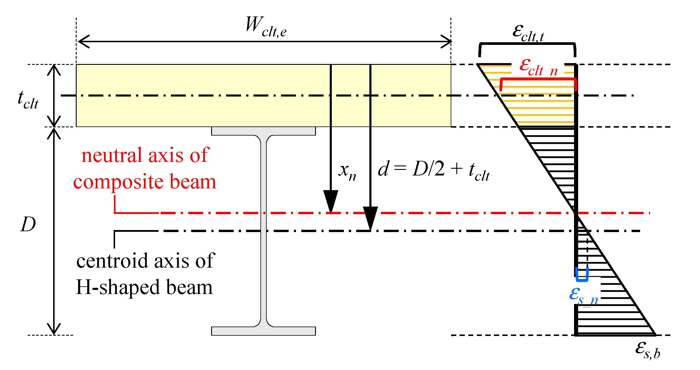
- Using the static friction force of the high-strength bolt friction joint obtained in (1), the effective width of the CLT floor panel estimated in (3), and the material properties, it was demonstrated that the initial flexural stiffness and yield bending moment can be estimated by applying the plane-section assumption to the composite beam cross-section, as described in Figure 12 and Equations (3), (9) and (12).
- (i)
- Clarification of the relationship between optimal bolt axial preload and static friction force, considering the number of bolts and their spacing, as well as the effects of environmental factors and aging on the static friction force at the CLT–steel interface. This includes examining the influence of temperature, humidity, usage conditions, CLT thickness, stiffness, fiber direction, and thermal expansion on both structural performance and building serviceability.
- (ii)
- Determination of the effective width of the CLT floor panels at the full-scale cross-section level.
- (iii)
- Evaluation of the serviceability and seismic performance of CLT floor panel–H-steel composite beams, including the applicability range of the simplified evaluation method for bending stiffness and yield bending strength based on Equations (3)–(13) and the assessment of their ultimate strength.
- (iv)
- Analysis of the seismic response characteristics of a building due to the use of low-axial-stiffness CLT floor panels.
- (v)
- Assessment of the advantages of steel structures incorporating CLT floor panels from both environmental and disaster resilience perspectives, including the estimation of total costs from construction to demolition. The assessment should also consider the environmental impact of the adhesives used in CLT panels [57].
Author Contributions
Funding
Data Availability Statement
Acknowledgments
Conflicts of Interest
Nomenclature
| Symbol | Unit | Description |
| a | mm | Distance between the edges of the upper flanges of adjacent beams |
| As | mm2 | Cross-sectional area of H-shaped steel beam |
| b | mm | Floor width of the beam |
| D | mm | Depth of the steel beam |
| Eclt | N/mm2 | Young’s modulus of CLT |
| Eclt,b | N/mm2 | Young’s modulus of CLT in bending |
| Eclt,c | N/mm2 | Young’s modulus of CLT in compression |
| Es | N/mm2 | Young’s modulus of steel |
| Icf | mm4 | Second moment of area of composite beam |
| Iclt | mm4 | Second moment of area of CLT |
| Icp | mm4 | Second moment of area of partially composite beam |
| Is | mm4 | Second moment of area of H-shaped steel beam |
| Ke,s | kN/mm | Initial stiffness of H-shaped steel beam |
| l | mm | Length of the beam |
| L | mm | Span of beam |
| Ms,p | kNm | Fully plastic moment of H-shaped steel beam |
| Ms,y | kNm | Yield moment of H-shaped steel beam |
| nb | - | Number of high-strength bolts required for a fully composite beam up to the point where the steel reaches its yield strength |
| nf | - | Number of studs required for a fully composite beam |
| np | - | Number of studs connecting the reinforced-concrete slab |
| Nf | kN | Static friction force between CLT and steel plate |
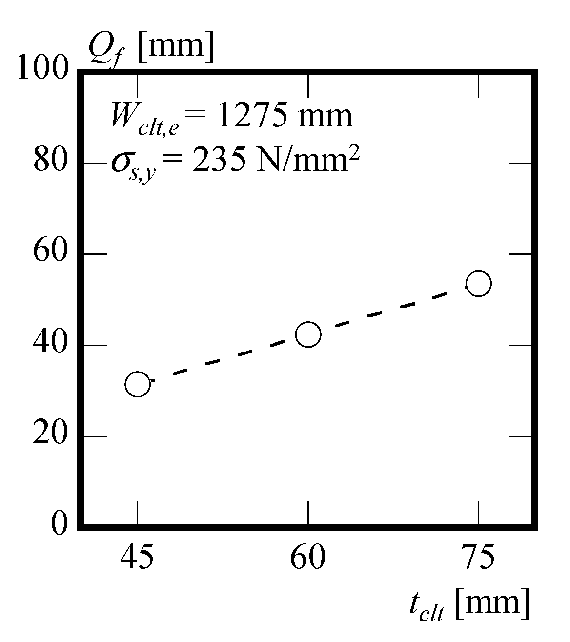
| Qf | kN | Shear force occurring between the steel beam and the CLT floor panels of a fully composite beam when the tensile strain at the bottom of the steel beam reaches the yield strain |
| Qp | kN | Yield strength of the connection between the floor panel and the steel beam |
| tclt | mm | Thickness of CLT slab |
| Wclt | mm | Width of CLT panel |
| Wclt,e | mm | Effective floor width of the floor panel |
| xn | mm | Neutral axis of the composite beam |
| Zcf | mm3 | Section modulus of the fully composite beam |
| Zcp | mm3 | Section modulus of partially composite beam |
| Zs | mm3 | Section modulus of H-shaped steel beam |
| δ | mm | Central deflection of composite beam |
| εclt | - | Equivalent compressive strain of CLT under clamping force from high-strength bolt |
| εclt_n | - | Axial strains occurring in the CLT |
| εclt,t | - | Strain at the top surface of the slab |
| εs_n | - | Axial strains occurring in the steel |
| εs,y | - | Yield strain of steel |
| ϕ | ° | Rotation angle of high-strength bolt |
| ϕ0 | ° | Optimal bolt rotation angle for four-point loading test |
| σs,y | N/mm2 | Yield stress of the steel beam |
References
- Available online: https://www.iea.org/commentaries/the-energy-efficiency-policy-package-key-catalyst-for-building-decarbonisation-and-climate-action (accessed on 13 January 2025).
- Chen, Z.; Gu, H.; Bergman, R.D.; Liang, S. Comparative Life-Cycle Assessment of a High-Rise Mass Timber Building with an Equivalent Reinforced Concrete Alternative Using the Athena Impact Estimator for Buildings. Sustainability 2020, 12, 4708. [Google Scholar] [CrossRef]
- Zhang, J.; Asutosh, A.T.; Zhang, Y. Sustainability Research of Building Systems Based on Neural Network Predictive Models and Life Cycle Assessment (LCA)–Emergy–Carbon Footprint Method. Sustainability 2024, 16, 329. [Google Scholar] [CrossRef]
- Hart, J.; D’Amico, B.; Pomponi, F. Whole-Life Embodied Carbon in Multistory Buildings: Steel, Concrete, and Timber Structures. J. Ind. Ecol. 2021, 25, 403–418. [Google Scholar] [CrossRef]
- Suer, J.; Traverso, M.; Jäger, N. Review of Life Cycle Assessments for Steel and Environmental Analysis of Future Steel Production Scenarios. Sustainability 2022, 14, 14131. [Google Scholar] [CrossRef]
- Kiessling, S.; Gohari Darabkhani, H.; Soliman, A.-H. Greater Energy Independence with Sustainable Steel Production. Sustainability 2024, 16, 1174. [Google Scholar] [CrossRef]
- Berglund-Brown, J. Structural Steel Reuse as a Cost-Effective Carbon Mitigation Strategy. Master’s Thesis, Massachusetts Institute of Technology, Cambridge, MA, USA, 2023. [Google Scholar]
- Piccardo, C.; Steinik, C.; Caffè, S.; Argentoni, A.; Calderini, C. Primary Energy and Carbon Impacts of Structural Frames with Equivalent Design Criteria: Influence of Different Materials and Levels of Prefabrication. Sustainability 2024, 16, 4209. [Google Scholar] [CrossRef]
- Brütting, J.; Desruelle, J.; Senatore, G.; Fivet, C. Design of Truss Structures Through Reuse. Structures 2019, 18, 128–137. [Google Scholar] [CrossRef]
- Broniewicz, E.; Dec, K. Environmental Impact of Demolishing a Steel Structure Design for Disassembly. Energies 2022, 15, 7358. [Google Scholar] [CrossRef]
- Kanyilmaz, A.; Birhane, M.; Fishwick, R.; del Castillo, C. Reuse of Steel in the Construction Industry: Challenges and Opportunities. Int. J. Steel Struct. 2023, 23, 1399–1416. [Google Scholar] [CrossRef]
- Brütting, J.; Vandervaeren, C.; Senatore, G.; De Temmerman, N.; Fivet, C. Environmental impact minimization of reticular structures made of reused and new elements through Life Cycle Assessment and Mixed-Integer Linear Programming. Energy Build. 2020, 215, 109827. [Google Scholar] [CrossRef]
- Brütting, J.; De Wolf, C.; Fivet, C. The Reuse of Load-Bearing Components. IOP Conf. Ser. Earth Environ. Sci. 2019, 225, 012025. [Google Scholar] [CrossRef]
- Connolly, D.; Hansen, K.; Drysdale, D.; Sayegh, A. Decision-Making for the Demolition or Adaptation of Existing Structures: Sustainability Considerations. J. Environ. Manag. 2023, 325, 116504. [Google Scholar] [CrossRef]
- Architectural Institute of Japan (AIJ). Recommendation for Sustainable Steel Building Construction (Draft)-Member Reuse; Maruzen Publishing Co., Ltd.: Tokyo, Japan, 2015. (In Japanese) [Google Scholar]
- Minunno, R.; O’Grady, T.; Morrison, G.M.; Gruner, R.L. Exploring environmental benefits of reuse and recycle practices: A circular economy case study of a modular building. Resour. Conserv. Recycl. 2020, 160, 104855. [Google Scholar] [CrossRef]
- Li, J.; Andersen, L.V.; Hudert, M.M. The Potential Contribution of Modular Volumetric Timber Buildings to Circular Construction: A State-of-the-Art Review Based on Literature and 60 Case Studies. Sustainability 2023, 15, 16203. [Google Scholar] [CrossRef]
- Blok, R.; Teuffel, P. Demolition versus Transformation: “Mortality of Building Structures” Depending on Their Technical Building Properties. IOP Conf. Ser. Earth Environ. Sci. 2019, 225, 012016. [Google Scholar] [CrossRef]
- Darby, H.; Elmualim, A.A.; Kelly, F. A Case Study to Investigate the Life Cycle Carbon Emissions and Carbon Storage Capacity of a cross Laminated Timber, Multi-Storey Residential Building. In Proceedings of the Sustainable Building Conference, Munich, Germany, 24–26 April 2013. [Google Scholar]
- Abed, J.; Rayburg, S.; Rodwell, J.; Neave, M. A Review of the Performance and Benefits of Mass Timber as an Alternative to Concrete and Steel for Improving the Sustainability of Structures. Sustainability 2022, 14, 5570. [Google Scholar] [CrossRef]
- Greene, J.M.; Hosanna, H.R.; Willson, B.; Quinn, J.C. Whole Life Embodied Emissions and Net-Zero Emissions Potential for a Mid-Rise Office Building Constructed with Mass Timber. Sustain. Mater. Technol. 2023, 35, e00528. [Google Scholar] [CrossRef]
- Forestry Agency of Japan. New Wooden Public Building in Japan: Ten Case Studies. Tokyo, Japan. 2017. Available online: https://www.rinya.maff.go.jp/j/riyou/kidukai/attach/pdf/kihonhousin-7.pdf (accessed on 6 January 2025). (In Japanese).
- Nakano, K.; Karube, M.; Hattori, N. Environmental Impacts of Building Construction Using Cross-Laminated Timber Panel Construction Method: A Case of the Research Building in Kyushu, Japan. Sustainability 2020, 12, 2220. [Google Scholar] [CrossRef]
- Harada, H.; Saito, R.; Nakajima, S.; Yamazaki, Y.; Terazawa, Y.; Hayashi, K.; Sakata, H.; Takeuchi, T. Cyclic elasto-plastic deformation capacity of dog bone timber-steel hybrid connections. J. Struct. Constr. Eng. (Trans. AIJ) 2020, 85, 945–955. [Google Scholar] [CrossRef]
- Becker, I.; Anderson, F.; Phillips, A.R. Structural Design of Hybrid Steel-Timber Buildings for Lower Production Stage Embodied Carbon Emissions. J. Build. Eng. 2023, 76, 107053. [Google Scholar] [CrossRef]
- Loss, C.; Piazza, M.; Zandonini, R. Connections for steel-timber hybrid prefabricated buildings. Part II: Innovative modular structures. Constr. Build. Mater. 2016, 122, 796–808. [Google Scholar] [CrossRef]
- Hassanieh, A.; Valipour, H.R.; Bradford, M.A. Experimental and numerical study of steel-timber composite (STC) beams. J. Constr. Steel Res. 2016, 122, 367–378. [Google Scholar] [CrossRef]
- Hassanieh, A.; Valipour, H.R.; Bradford, M.A. Load-slip behaviour of steel-cross laminated timber (CLT) composite connections. J. Constr. Steel Res. 2016, 122, 110–121. [Google Scholar] [CrossRef]
- Hassanieh, A.; Valipour, H.R.; Bradford, M.A. Experimental and numerical investigation of short-term behaviour of CLT-steel composite beams. Eng. Struct. 2017, 144, 43–57. [Google Scholar] [CrossRef]
- Hassanieh, A.; Valipour, H.R.; Bradford, M.A. Composite connections between CLT slab and steel beam: Experiments and empirical models. J. Constr. Steel Res. 2017, 138, 823–836. [Google Scholar] [CrossRef]
- Chybiński, M.; Polus, Ł. Experimental and Numerical Investigations of Aluminium-Timber Composite Beams with Bolted Connections. Structures 2021, 34, 1942–1960. [Google Scholar] [CrossRef]
- Chybiński, M.; Polus, Ł. Mechanical Behaviour of Aluminium-Timber Composite Connections with Screws and Toothed Plates. Materials 2022, 15, 68. [Google Scholar] [CrossRef]
- Chybiński, M.; Polus, Ł. Experimental Study of Aluminium-Timber Composite Bolted Connections Strengthened with Toothed Plates. Materials 2022, 15, 5271. [Google Scholar] [CrossRef]
- Liu, R.; Liu, J.; Wu, Z.; Chen, L.; Wang, J. A Study on the Influence of Bolt Arrangement Parameters on the Bending Behavior of Timber–Steel Composite (TSC) Beams. Buildings 2022, 12, 2013. [Google Scholar] [CrossRef]
- Wang, C.-L.; Lyu, J.; Zhao, J.; Yang, H. Experimental investigation of the shear characteristics of steel-to-timber composite joints with inclined self-tapping screws. Eng. Struct. 2020, 215, 110683. [Google Scholar] [CrossRef]
- Zhao, Y.; Yuan, Y.; Wang, C.-L.; Zheng, J.; Zhou, Y. Experimental study on shear performance of steel-timber screw connectors with grout pockets. Eng. Struct. 2022, 266, 114535. [Google Scholar] [CrossRef]
- Zhou, Y.; Zhao, Y.; Wang, C.-L.; Zhou, Y.; Zheng, J. Experimental study of the shear performance of H-shaped aluminum-timber composite connections. Constr. Build. Mater. 2022, 334, 127421. [Google Scholar] [CrossRef]
- Zhao, Y.; Yuan, Y.; Wang, C.; Meng, S. Experimental and finite element analysis of flexural performance of steel-timber composite beams connected by hybrid-anchored screws. Eng. Struct. 2023, 292, 116503. [Google Scholar] [CrossRef]
- Ataei, A.; Chiniforush, A.A.; Bradford, M.A.; Valipour, H.R.; Ngo, T.D. Behaviour of embedded bolted shear connectors in steel-timber composite beams subjected to cyclic loading. J. Build. Eng. 2022, 54, 104581. [Google Scholar] [CrossRef]
- Kuratomi, Y.; Sakai, J.; Inada, T. An Experimental Study on Composite Effect of Steel Beam and CLT floor. Summ. Tech. Pap. Annu. Meet. Archit. Inst. Jpn. Kyushu Branch 2019, 58, 553–556. (In Japanese) [Google Scholar]
- Kuratomi, Y.; Inada, T.; Sakai, J. Study on the Development of the Wooden Hybrid Structural System with Lag-Screw Bolts. In Proceedings of the International Structural Engineering and Construction, Fukuoka City, Japan, 10–11 October 2023; Volume 10. [Google Scholar]
- Suzuki, A.; Kimura, Y.; Matsuda, Y.; Kasai, K. Rotation capacity of I-shaped beams with concrete slab in buckling-restrained braced frames. J. Struct. Eng. 2024, 150, 04023204. [Google Scholar] [CrossRef]
- Suzuki, A.; Kimura, Y. Rotation capacity of I-shaped beam failed by local buckling in buckling-restrained braced frames with rigid beam-column connections. J. Struct. Eng. 2023, 149, 04022243. [Google Scholar] [CrossRef]
- Suzuki, A.; Kimura, Y. Rotation capacity of I-beams under cyclic loading with different kinematic/isotropic hardening characteristics. J. Constr. Steel Res. 2024, 223, 109007. [Google Scholar] [CrossRef]
- Japanese Agricultural Standard (JAS). JAS 3079; Cross Laminated Timber. Ministry of Agriculture, Forestry and Fisheries: Tokyo, Japan, 2019.
- Japanese Industrial Standard (JIS). JISB1186: 213; Sets of High Strength Hexagon Bolt, Hexagon Nut and Plain Washers for Friction Grip Joint. Japanese Standards Association: Tokyo, Japan, 2013. (In Japanese)
- Japanese Industrial Standards (JIS). JIS G 3136:2012; Rolled Steels for Building Structure. Japanese Standards Association: Tokyo, Japan, 2010. (In Japanese)
- Yoshino, Y.; Liao, W.; Kimura, Y. Restraint Effect on Lateral Buckling Load of Continuous Braced H-Shaped Beams Based on Partial Frame Loading Tests. J. Struct. Constr. Eng. (Trans. AIJ) 2022, 87, 534–645. [Google Scholar] [CrossRef]
- Understandable Steel Structures, 3rd ed.; Japan Society of Steel Construction: Tokyo, Japan, 2008; pp. 154–196.
- Design Guidebook for CLT Buildings; Japan Cross Laminated Timber Association: Tokyo, Japan, 2024; Available online: https://clta.jp/wp-content/themes/clt/pdf/about/nyukai/pdf_guidebook.pdf (accessed on 29 December 2024).
- Research Results Presentation: “Adopting CLT for Flooring in Steel-Structured Office Buildings”; Fiscal Year 2013 Revised Budget; Japan Forestry Agency: Tokyo, Japan, 2015.
- Architectural Institute of Japan (AIJ). Design Recommendations for Composite Constructions; Maruzen Publishing Co., Ltd.: Tokyo, Japan, 2012. (In Japanese) [Google Scholar]
- American Institute of Steel Construction (AISC). Specification for the Design, Fabrication and Erection of Structural Steel for Buildings; American Institute of Steel Construction (AISC): Chicago, IL, USA, 1978. [Google Scholar]
- Masoudnia, R.; Hashemi, A.; Quenneville, P. Predicting the Effective Flange Width of a CLT slab in Timber Composite Beams. J. Struct. Eng. 2018, 144, 04018084. [Google Scholar] [CrossRef]
- Grant, J.; John, A.; Roger, G.R.; Fisher, W.J. Composite Beams with Formed Steel Deck. Eng. J. 1977, 14, 24–43. [Google Scholar] [CrossRef]
- Architectural Institute of Japan (AIJ). AIJ Standard for Allowable Stress Design of Steel Structures; Maruzen Publishing Co., Ltd.: Tokyo, Japan, 2019. (In Japanese) [Google Scholar]
- Nakano, K.; Koike, W.; Yamagishi, K.; Hattori, N. Environmental Impacts of Cross-Laminated Timber Production in Japan. Clean Technol. Environ. Policy 2020, 22, 2193–2205. [Google Scholar] [CrossRef]


| Grade | Young’s Modulus in Bending [GPa] | Flexural Strength [MPa] | Tensile Strength [MPa] | ||||
|---|---|---|---|---|---|---|---|
| Average | Min. | Max. | Average | Min. | Average | Min. | |
| M60B | 6.0 | 5.0 | 9.0 | 27.0 | 20.0 | 16.0 | 12.0 |
| Specimen | Bolt Size | Steel Plate Washer Size | Thickness of CLT Panel tclt [mm] | Bolt Rotation Angle ϕ [Degree] |
|---|---|---|---|---|
| t45-ϕ **1 | M16 | 50 × 80 × 10 | 45 | 60, 120, 180, 270, 360, 450 |
| t45-ϕ **1 | 60 | 60, 120, 180, 270, 360, 450, 540 | ||
| t45-ϕ **1 | 75 | 60, 120, 180, 270, 360, 450, 540 |
| Specimen | Steel Beam | CLT Panel | Bolt Tightening Angle ϕ0 | |
|---|---|---|---|---|
| Section | Section (Material Type) | Thickness (Direction) | ||
| H | H200 × 100 × 5.5 × 8 (SN400B) | - | - | - |
| CLT-H-45W | S60-3-3 (M60B) | 45 (weak axis) | 240° | |
| CLT-H-60W | 60 (weak axis) | 300° | ||
| CLT-H-75W | 75 (weak axis) | 360° | ||
| CLT-H-60S | 60 (strong axis) | 300° | ||
| Young’s Modulus Es [N/mm2] | Yielding Stress σs,y [N/mm2] | |
|---|---|---|
| Web | 202,300 | 397 |
| flange | 211,800 | 324 |
| Young’s Modulus Eclt,b | ||
|---|---|---|
| In Bending Eclt,b [N/mm2] | In Compression Eclt,c [N/mm2] | |
| Weak axis | 700 | 2500 |
| Strong axis | 6100 | 4500 |
Disclaimer/Publisher’s Note: The statements, opinions and data contained in all publications are solely those of the individual author(s) and contributor(s) and not of MDPI and/or the editor(s). MDPI and/or the editor(s) disclaim responsibility for any injury to people or property resulting from any ideas, methods, instructions or products referred to in the content. |
© 2025 by the authors. Licensee MDPI, Basel, Switzerland. This article is an open access article distributed under the terms and conditions of the Creative Commons Attribution (CC BY) license (https://creativecommons.org/licenses/by/4.0/).
Share and Cite
Furukawa, S.; Iwami, R.; Kimura, Y. Development of an Environmentally Friendly Steel Structural Framework: Evaluation of Bending Stiffness and Yield Bending Moment of Cross-Laminated Timber Slab–H-Shaped Steel Composite Beams for Component Reuse. Sustainability 2025, 17, 2073. https://doi.org/10.3390/su17052073
Furukawa S, Iwami R, Kimura Y. Development of an Environmentally Friendly Steel Structural Framework: Evaluation of Bending Stiffness and Yield Bending Moment of Cross-Laminated Timber Slab–H-Shaped Steel Composite Beams for Component Reuse. Sustainability. 2025; 17(5):2073. https://doi.org/10.3390/su17052073
Chicago/Turabian StyleFurukawa, Sachi, Ryohei Iwami, and Yoshihiro Kimura. 2025. "Development of an Environmentally Friendly Steel Structural Framework: Evaluation of Bending Stiffness and Yield Bending Moment of Cross-Laminated Timber Slab–H-Shaped Steel Composite Beams for Component Reuse" Sustainability 17, no. 5: 2073. https://doi.org/10.3390/su17052073
APA StyleFurukawa, S., Iwami, R., & Kimura, Y. (2025). Development of an Environmentally Friendly Steel Structural Framework: Evaluation of Bending Stiffness and Yield Bending Moment of Cross-Laminated Timber Slab–H-Shaped Steel Composite Beams for Component Reuse. Sustainability, 17(5), 2073. https://doi.org/10.3390/su17052073