Abstract
The aim of this article is to examine existing technologies for the use of electrical energy and to develop proposals for their improvement on maritime vessels. As a criterion for evaluating the effectiveness of alternative energy sources on ships, factors such as greenhouse gas emissions levels, production and transportation characteristics, onboard storage conditions, and technoeconomic indicators have been proposed. The analysis of fuel types reveals that hydrogen has zero greenhouse gas emissions. However, transportation and storage issues, along with the high investment required for implementation, pose barriers to the widespread use of hydrogen as fuel for maritime vessels. This article demonstrates that solar energy can serve as an alternative to gases and liquid fuels in maritime transport. The technologies and challenges in utilizing solar energy for shipping are analyzed, trends in solar energy for maritime transport are discussed, and future research directions for the use of solar energy in the maritime sector are proposed. The most significant findings include the identification of future research directions in the application of solar energy in the maritime sector, including the adaptation of concentrated solar power (CSP) systems for maritime applications; the development of materials and designs for solar panels specifically tailored to marine conditions; the development of methods for assessing the long-term economic benefits of using solar energy on vessels; and the creation of regulatory frameworks and international standards for the use of solar energy on ships. Furthermore, for hybrid photovoltaic and diesel power systems, promising research directions could include efforts to implement direct torque control systems instead of field-orientated control systems, as well as working on compensating higher harmonics in the phase current spectra of asynchronous motors.
1. Introduction
Maritime transport dominates international trade with large volumes of cargo and has the greatest impact on supporting economic growth and globalization [1]. For many years, maritime trade has been the most important type of international transportation. It makes up more than 80% of the world’s trade. The volume of maritime trade has increased by 3% each year in the last 40 years [2].
Maritime transportation and related infrastructure directly or indirectly affect a wide range of industries with a large overall impact on the economy [3,4]. Maritime transport is considered to be the backbone of global trade [3]. Many resources transported by sea are shipped to manufacturing centers. As a result, many other sectors of the economy are highly dependent on maritime transportation. Logistics hubs and port activities are components of maritime transportation. They have a major impact on the development of maritime sectors and trade. This fact contributes to economic growth and job creation.
In the European Union (EU), maritime transport accounts for more than three-quarters of external trade and one-third of internal trade [3]. Twenty-two countries are involved in maritime transport between EU members. As a result, European shipping accounts for a large share of the world fleet (more than 40%) and forms some of the largest maritime clusters in the world. Maritime transport affects not only economic growth and development but also the environment. The Green Pact identifies the problems and sets out the pollution reduction policies of the EU member states, according to which measures should be taken to reduce pollution from the maritime sector [3]. The maritime industry is ready to embrace innovative solutions that not only reduce greenhouse gas (GHG) emissions but also improve energy efficiency in the sector [5,6,7].
Carbon dioxide (CO2) emissions have detrimental effects on natural ecosystems. First and foremost, CO2 is the primary greenhouse gas significantly contributing to global warming and climate change [8,9,10]. This phenomenon leads to serious consequences, such as escalating Earth’s surface temperature, melting glaciers, and rising sea levels [11,12,13]. Oceans, by absorbing excess CO2, become more acidic, creating threats to marine ecosystems, including coral reefs and marine fauna. Changes in precipitation patterns and air temperature also affect plant and animal life, leading to decreased biodiversity. Reducing these emissions is imperative for maintaining the stability of natural systems and the planet’s biological diversity [14]. Data presented in ref. [14] indicate a trend of increasing CO2 emissions since 1990. This observation is significant in the context of combating climate change as CO2 is one of the main greenhouse gases contributing to the greenhouse effect and global warming.
The trend of increasing CO2 emissions poses a significant threat to our planet and emphasizes the importance of adopting long-term and effective measures to reduce them. The International Maritime Organization (IMO) requires the shipping industry to reduce annual GHG emissions by 2050 by at least 50% of 2008 levels. The fourth IMO study on greenhouse gases used 2008 as the baseline year. According to the study, greenhouse gas emissions from shipping will increase by 90–130% by 2050 without significant decarbonization. To achieve zero emissions, the shipping industry will need to take comprehensive action from a number of perspectives to counter the adverse effects of global warming [15,16,17].
Some approaches to this problem include a shift to renewable energy sources and improvements in energy efficiency. The last includes not only energy savings in homes and businesses but also the optimization of energy production processes, resulting in higher energy yields with reduced CO2 emissions. Furthermore, reducing waste and improving industrial production efficiency, for example, through the implementation of cleaner technologies and optimization of resource use, also contribute to reducing overall carbon dioxide emissions [18]. Achieving sustainable development in the maritime sector requires several key actions: the development of marine technologies, the implementation of renewable energy sources, and a reduction in harmful emissions.
2. Literature Review
A promising solution to reduce GHG emissions and combat climate change in the offshore industry is the use of renewable energy sources. Such sources include solar energy, wind energy, and hybrid systems. The application of such energy sources in the shipping industry can play a crucial role in protecting the environment and combating global warming [19,20,21].
The focus on improving marine technology and the use of renewable energy is crucial. These measures directly contribute to reducing CO2 emissions and addressing climate change. Furthermore, raising public awareness and creating legal and economic incentives are vital to support these efforts and ensure sustainable and environmentally responsible use of marine resources for future generations. In modern shipping, alternative fuels are being actively researched to reduce environmental impact [22].
The main options include natural gas, hydrogen, ammonia, methanol, biodiesel, and electricity liquefied natural gas (LNG), which is already widely used because of its low GHG emissions and high energy efficiency. Hydrogen is attractive for its zero emissions during combustion but faces storage and production challenges. Although special precautions must be taken, ammonia looks promising as a hydrogen carrier. Methanol is distinguished by its ease of handling and potential for production from renewable sources. Biodiesel is compatible with existing engines and provides reduced greenhouse gas emissions [23,24,25].
The marine industry faces an urgent environmental challenge. Researchers, industry stakeholders, policymakers, and experts in the field are looking for innovative solutions to reduce GHG emissions [26,27,28]. Among these, the integration of solar energy and Carbon Capture, Utilization, and Storage (CCUS) technologies has emerged as a promising pathway.
The integration of solar energy into maritime operations marks a monumental shift in how ships navigate the seas. Ships, previously synonymous with emissions and environmental harm, have undergone an extraordinary transformation. Now, through the pervasive power of the sun, they embrace environmental sustainability like never before. Modern vessels proudly display solar panels, strategically positioned on their decks and structures, silently converting sunlight into clean renewable energy. This implementation of solar technology signifies a decisive departure from traditional fuel sources, promising not only cost savings but also significant environmental impact reduction [29].
When implementing solar energy as an alternative fuel on marine vessels, technical challenges were identified, such as effective panel placement and performance under adverse weather conditions. The economic viability of solar integration on large cargo vessels remains a subject of debate [30,31].
Improving the efficiency and reliability of solar panels, expanding their realization, and exploring new materials to improve performance are the focus of much research and development. These benefits not only improve vessel operational efficiency but also make a significant contribution to the global pursuit of more environmentally friendly and responsible maritime practices [32,33].
Despite the valuable insights gained from existing research, there are notable gaps that require attention. These gaps encompass technical challenges, economic viability assessment, understanding of regulatory frameworks, knowledge dissemination, and conducting comparative studies. Addressing these gaps is crucial for further progress in the maritime industry.
Future prospects depend on technological improvements aimed at overcoming existing challenges, increasing overall efficiency, and aligning the maritime sector with global environmental goals, as noted in various studies [34]. These areas of focus promise to shape the industry’s trajectory toward a cleaner and more efficient future.
The aim of the article is to review existing electrical power technologies and develop proposals for their improvement on marine vessels. The research contributions of the article are as follows: (1) an analysis of alternative fuels used on marine vessels was performed, using criteria such as greenhouse gas emissions levels, production and transportation characteristics, and onboard storage specifics; (2) technical and economic indicators were analyzed for the introduction of alternative fuels on marine vessels; (3) technologies and challenges of solar energy use in shipping were analyzed; (4) trends in solar energy for maritime transport were analyzed; and (5) future research directions for solar energy use in the maritime sector were proposed.
The article has the following structure:
- Section 3 describes research methodologies and data.
- Section 4 presents an analysis of alternative fuels used on marine vessels.
- Section 5 analyzes technologies that use solar energy in shipping and their technical and economic performance.
- Section 6 analyzes the challenges and trends in the use of solar energy for maritime transport.
- Section 7 discusses the obtained results and proposes future research directions for solar energy use in the maritime sector.
- Section 8 presents conclusions.
3. Description of Research Methodology and Data
The research methodology was chosen on the basis of the following considerations. As noted above, the use of alternative fuels on marine vessels contributes to the reduction in GHG emissions into the environment. Furthermore, the use of alternative fuels will increase the energy efficiency of both the main and auxiliary drives of a marine vessel. At the same time, each type of alternative fuel has its own specifics in production and the conditions of storage on the ship.
Energy efficiency, the cost of production, delivery to the ship, and the storage of the alternative fuel on board also affect the economics of using this type of fuel compared to conventional fuel. Therefore, the following criteria were selected to compare the performance of alternative fuels:
- The level of GHG emissions to the environment.
- Energy efficiency.
- Features of production and transportation.
- Features of storage on board ship.
- Economic efficiency.
The following sources were used to address these research objectives: Refs. [35,36,37,38,39] to compare the efficiency of LNG application; Refs. [35,39,40,41,42] to compare the efficiency of methanol application; Refs. [43,44,45,46,47] to compare the efficiency of hydrogen application; Refs. [48,49,50,51] to compare the efficiency of ammonia application; and Refs. [52,53] to compare the efficiency of biofuel application.
This research approach allowed us to demonstrate the effectiveness of solar energy as an alternative energy source for marine vessels. The analysis of the efficiency of technologies using solar energy as an alternative power source was carried out by comparing photovoltaic (PV) panel technologies with concentrated solar power (CSP) systems. The analysis was based on the data presented in the study [54]. As a result of the analysis, the challenges related to the use of solar energy on ships were identified, and possible solutions were proposed. Since the highest energy consumption and GHG emissions are attributed to large-displacement cargo ships, the study utilized data specifically for this type of vessel.
4. Analysis of Alternative Fuels Used on Marine Vessels
Addressing climate change and reducing GHG emissions are critically important challenges. Maritime vessels, which contribute significantly to global emissions, face increasing pressure to adopt cleaner and more sustainable energy sources. Data from the Fourth IMO GHG Study 2020 indicate that the share of global anthropogenic GHG emissions attributed to the shipping industry has increased from 2.76% to 2.89% [55]. This growing impact emphasizes the urgency of aligning maritime operations with environmental objectives.
The number of vessels using various types of fuel, both in operation and under construction, continues to increase (Figure 1). When constructing Figure 1, the following number of vessels was considered, both in operation and in construction: hydrogen-powered—4485, LNG-powered—811, battery-powered—627, LNG-ready—829, LPG-powered—104, methanol-powered—56, and scrubber-equipped—8 [56].

Figure 1.
Number of vessels by fuel type [56].
The maritime sector is striving to reduce its carbon footprint. To supplement or replace traditional fuels, various alternative energy sources are being explored, including LNG, electric batteries, and hydrogen. Solar energy, while still at an experimental stage for larger vessels, shows potential due to its renewable nature and compatibility with other energy systems.
The development of technologies and the use of alternative energy sources contribute to reducing GHG emissions in the sector and addressing the issue of climate change [57]. Furthermore, raising public awareness and creating legal and economic incentives are vital to support these efforts and ensure the sustainable and environmentally responsible use of marine resources for future generations.
4.1. Liquefied Natural Gas
In the maritime industry, liquefied natural gas (LNG) is considered one of the most promising alternative fuels. Compared to traditional oil-based fuels, the use of LNG as a marine fuel offers several advantages. These benefits include a significant reduction in sulfur oxide (SOx) and particulate emissions, as well as a decrease in nitrogen oxide (NOx) and carbon dioxide (CO2) emissions [58,59,60]. However, the implementation of LNG requires substantial investments in infrastructure and vessel modifications, which is one of the main challenges for the widespread adoption of this technology.
4.1.1. Environmental Impact of LNG-Powered Vessels
The consumers of LNG in maritime vessels are the main and auxiliary engines. During operation, these engines emit greenhouse gases into the atmosphere [61]. The primary greenhouse gas consists of methane (CH4). At a temperature of −160 °C and atmospheric pressure, this gas becomes liquid. Compared to heavy fuel oil (HFO), which is used as the main fuel on maritime vessels, LNG is a cleaner fuel. It is used to reduce SOx, NOx, and particulate emissions [35]. The IMO’s Fourth Study showed that, due to the growing number of vessels, methane emissions from the combustion of LNG in engines increased by 150% from 2012 to 2018. This led to a rise in GHG emissions [62].
In ref. [36], a comparison of fuel consumption and emissions was made for the operation of main engines (Table 1) and auxiliary engines (Table 2) in maritime vessels running on LNG and HFO.

Table 1.
Data for annual GHG emissions assessment TtW for main engines using LNG [36].
Table 2.
Emission factors for annual TtW GHG emissions assessment from auxiliary engine [36].
The nominal power of the main engine, load factor, type of fuel, engine type, and year of manufacture are factors that influence GHG emissions. Changes in the operational parameters of the vessel over time lead to variations in the power output and load factor of the main engine [37]. The output power required to propel the vessel is a function of the operational speed and is expressed as the “load”, representing a share of the total installed maximum continuous rating (MCR) [37]. In this study, abstract ship log (LOG) data were used. The average main engine load at sea was assumed to be 72.5% of MCR. This load was converted into specific fuel consumption (SFC) for both HFO and LNG. For dual-fuel engines operating on LNG and HFO, the amount of fuel used is a function of the engine load.
Figure 2 shows a comparison of annual TtW emission estimates from vessels using HFO and LNG in main and auxiliary engines [36]. The highest level of greenhouse gas emissions is demonstrated by a vessel operating on HFO, while vessels with LS-HPDF using LNG show the lowest indicators. The emission volumes for these engines are approximately 17,689 t for HFO, 12,463 t for LS-HPDF, and 15,806 t for LS-LPDF. Overall, emissions from auxiliary engines account for only 5.2–7.3% of total annual TtW greenhouse gas emissions compared to main engines.
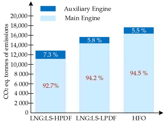
Figure 2.
Annual TtW GHG emissions for HFO and LNG [36].
Figure 3 shows the average greenhouse gas emission intensity for energy used onboard vessels for the given year, where all vessel emissions are considered only from main and auxiliary engines [36]. The trend in greenhouse gas emission intensity between fuel types follows a similar pattern to the annual greenhouse gas emissions shown in Figure 2. Based on the data presented in [36], Table 3 shows the specific fuel consumption (g/kWh) for HFO and LNG depending on the engine load.
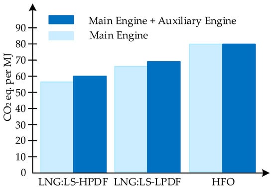
Figure 3.
Average energy intensity of emissions during the operation of engines on board the vessel, running on HFO and GHG [36].
Table 3.
Specific fuel consumption (g/kWh) for HFO and LNG depending on engine load [36].
The analysis of the results presented in Table 3 indicates a dependence of LNG consumption on the fuel combustion characteristics and the combustion cycles of the engines. From the data presented in Table 3, it can be concluded that engines operating on LNG have lower fuel consumption when operating under high load conditions. In [36], GHG emissions were calculated based on specific fuel consumption data for HFO and LNG, depending on the engine load. The results of these calculations are presented in Figure 4.
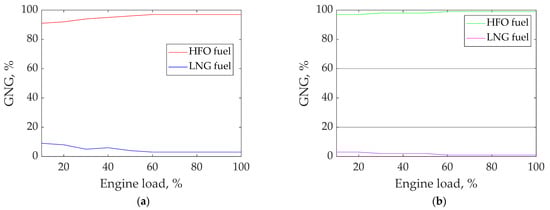
Figure 4.
GHG emission ratios for HFO and LNG: LS-HPDF (a) and HFO and LNG: LS-LPDF (b) as a function of main engine load.
4.1.2. Features of LNG Production and Transportation
The production of LNG is based on refrigeration cycles, such as steam compression and gas expansion. The main difference between these cycles is the presence of a phase change of the refrigerant in the steam compression cycle, while no such phase change occurs in the gas expansion cycle.
Both cycles include four main stages: (1) the compression of the refrigerant into a high-pressure hot stream (the compressor); (2) heat released from the compressed refrigerant (the condenser or cooler and heat exchanger); (3) the expansion of the compressed refrigerant into a low-pressure cold stream (the valve or expander); (4) heat absorbed by the cold refrigerant (the heat exchanger). In the final stage, cooling is provided for the natural gas. By repeating these four steps, natural gas can be continuously cooled [63].
LNG production can be carried out using one of the following three main technologies: Cascade, Mixed Refrigerant (MR), and Expander-based (EXP) [64]. Cascade technology uses three cooling cycles, each with different cooling levels. Each cycle has different levels of cooling. Pure propane, ethylene, and methane are used as refrigerants, respectively.
In MR technology, there is only one cooling cycle that uses a mixture of light hydrocarbons as the refrigerant. In the EXP process, pure nitrogen or methane is used as a refrigerant, which can reach low temperatures for liquefying natural gas in a single loop. Due to high energy consumption, EXP is less efficient compared to Cascade and MR technologies. Replacing the throttle valve with an expander helps recover part of the compressor work, thus reducing energy consumption during the EXP process. Table 4 demonstrates the advantages and disadvantages of the three LNG production technologies [63].
Table 4.
Advantages and disadvantages of the three LNG production technologies [63].
The assessment of the criteria for the three LNG technologies is based on a relative comparison. Because the Cascade process uses multiple refrigerants, it operates at several levels of cooling temperatures. This allows for a small temperature difference between the hot and cold sides in heat exchangers [65].
Using a refrigerant composed of a carefully selected hydrocarbon mixture, the MR process can replicate the cooling curve of natural gas. In contrast to the Cascade process, MR achieves a smaller temperature difference but requires a larger heat exchange area [64].
Throughout the entire EXP process, the pure refrigerant remains in the gaseous state, thereby ensuring a constant specific heat value for the cooling curve. EXP achieves a greater temperature difference between the natural gas and the refrigerant. This, in turn, results in high energy consumption [64]. Although a larger temperature difference reduces the required heat exchange area, it leads to a lower nitrogen heat transfer coefficient compared to hydrocarbons [64].
In the liquefaction process, the most expensive equipment is the heat exchanger, drive, and compressor. Therefore, the comparison of liquefaction processes is based on the type of refrigerant and the equipment listed. Based on the analysis of data presented in various studies, the following conclusions can be drawn:
- In liquefaction processes, either a mixed or a pure refrigerant is employed. In MR technology, a specially selected blend of hydrocarbons is used to replicate the cooling curve of natural gas. In Cascade technology, several distinct pure refrigerants with cascading boiling points throughout the cycles are utilized. In EXP technology, nitrogen or methane is employed. Owing to the extremely low boiling points of these gases, the liquefaction of natural gas is accomplished in a single cycle. The ranking of the processes by the temperature difference between the refrigerant and natural gas is as follows: MR less Cascade; Cascade less EXP. A reduction in energy consumption is achieved by maintaining a smaller temperature difference. Such a smaller temperature difference can be attained by increasing the heat exchange surface area, which in turn requires greater capital investments. From the above, it follows that the optimization of the gas liquefaction process can be accomplished by balancing the refrigerant zones and the heat exchanger design [65].
- Two primary types of heat exchangers are employed in LNG production: (1) the plate-fin or brazed aluminum type (PFHE) and (2) the spiral-wound heat exchanger type (SWHE). The advantages of PFHE include low pressure drops, versatility in accommodating fluctuations in low-temperature differentials, and a greater number of competitive suppliers. In contrast, the drawbacks of PFHE encompass the necessity for meticulous design and a pronounced susceptibility to physical damage, both of which are inherent to the aluminum construction of PFHE [63]. Among the advantages of SWHE are its higher reliability and ease of operation. However, its disadvantages include a higher cost, limited flexibility with respect to the feed gas composition, and less favorable mass and dimensional characteristics. Moreover, SWHE units are produced by only a few companies. Additionally, SWHE offers a higher maximum capacity (a single PFHE is rated at 1.5 million tons per year, whereas one SWHE can reach up to 4 million tons per year). The benefits and drawbacks of these heat exchanger types ultimately determine their application in various installations. For instance, Cascade and EXP installations employ PFHE, while SWHE is used in large-scale MR installations [65,66].
- Five types of drives and two types of compressors should be considered when analyzing the equipment used in liquefaction processes. The drive and compressor are adapted to the specific technology of the liquefaction process [64].
The transportation of LNG requires intermodal transportation, which combines road and rail transport modes. At railway stations, distribution centers should be organized to facilitate the distribution of LNG from suppliers to consumers [67]. Moreover, LNG logistics require transfer points between road and rail transportation modes and storage zones for holding LNG while awaiting transfer from one mode of transportation to another [38].
4.1.3. Features of LNG Storage on Marine Vessels
LNG has been transported by gas carriers since the 1960s. Compared to other industries, this form of transport has an excellent safety record [68]. Incidents that have occurred during LNG transportation have been minor [69]. According to [68], a total of 182 incidents have been recorded involving LNG carriers, none of which were severe accidents caused by LNG-related issues. The storage and supply systems for LNG on vessels are designed and operate similarly to those used on land-based LNG systems. LNG must be stored in pressure vessels at temperatures below −140 °C.
The risks associated with the use of LNG are related to its low temperature, the consequences of potential leaks, and failures of fuel system components [70]. Ensuring the safe design and operation of a vessel is achieved through a thorough examination of hazardous scenarios during the design phase [68].
The international code for the safety of ships using gases or other low-flashpoint fuels (IGF Code) has established fundamental rules for vessels using gases or other fuels with a low flashpoint. These rules are only partially mandatory to control hazardous scenarios. Amendments to these rules help improve the overall safety of the vessel’s systems. Since technology is relatively new, research on the general analysis of the safety and reliability of LNG supply systems remains limited.
4.2. Methanol
Methanol, primarily derived from renewable sources and produced through the hydrogenation of carbon dioxide, is an effective solution for reducing GHG emissions. Global scalability and compatibility with existing infrastructure (particularly LNG infrastructure) make methanol a cost-effective alternative with minimal disruption. Methanol is both efficient and economically viable, outperforming LNG, especially on new ships. Its use as a marine fuel provides flexibility without requiring special pressurized tanks.
Global trends in marine fuels emphasize fuel characteristics, availability, and environmental considerations, including factors such as policies, emissions, bunkering, and engine adaptability during the transition [71].
4.2.1. Environmental Impact of Methanol-Powered Marine Engines
In [36], comparative data are provided on fuel consumption and emissions during the operation of main (Table 5) and auxiliary (Table 6) engines of marine vessels powered by methanol and heavy fuel oil.
Table 5.
The results of the comparison of the annual greenhouse gas emissions (TtW) for main engines running on methanol and HFO [36].
Table 6.
Results of the comparison of the annual greenhouse gas emissions (TtW) for auxiliary engines running on LNG and HFO [36].
Considering the use of abstract data (LOG) for the vessel, as in the case of LNG, the average load of the main engine at sea was assumed to be 72.5% of the MCR. The load of the main engine, using specific fuel consumption (SFC) for HFO and methanol, was converted into fuel consumption.
The comparison of annual emissions (TtW) from the main and auxiliary engines of vessels using HFO and methanol is shown in Figure 5 [36]. The vessel operating on HFO produced higher greenhouse gas emissions than the vessel operating on methanol. The emissions of vessels that use these engines are approximately 17,689 t and 13,981.95 t, respectively. It can be seen in Figure 5 that the auxiliary engine emissions account for 5.5% to 7.3% of the total GHG emissions from TtW.

Figure 5.
Annual TtW GHG emissions for HFO and LNG [36].
The average energy intensity of GHG emissions throughout the year, when all the emissions of the vessel are considered only from the main and auxiliary engines, is shown in Figure 6 [36]. The trend in greenhouse gas emission intensity between fuel types is like the trend of annual greenhouse gas emissions shown in Figure 5.

Figure 6.
Average energy intensity of emissions from engines operating aboard the vessel on HFO and methanol [36].
Based on the data provided in [36], Table 7 presents the specific fuel consumption (g/kWh) for HFO and methanol depending on the engine load. The data presented (Table 7) indicate that under the main load range (40–60%), engines running on methanol will have the lowest fuel consumption. Based on the data on specific fuel consumption for HFO and methanol depending on engine load in work ref. [36], their GHG emissions were calculated. Figure 7 shows the results of these calculations.
Table 7.
Specific fuel consumption (g/kWh) for HFO and LNG depending on the engine load [36].
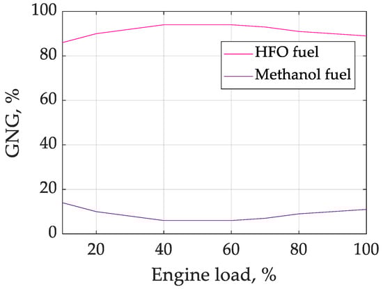
Figure 7.
Ratio of GHG emissions from HFO and methanol as a function of main engine load [36].
From the analysis of the results presented in Figure 7, it can be concluded that GHG emissions when using methanol are high at low (10–20%) and high (90–100%) engine loads, while they are lowest at medium loads (40–60%).
4.2.2. Methanol Production and Transportation Features
Coal and natural gas are the primary raw materials for methanol production. Alternative sources for methanol production can include wood, household and agricultural waste, renewable resources, and even CO2 [71]. CO2-based methanol synthesis mitigates the greenhouse effect and provides a wide range of chemical products and clean fuel [72].
Primary production includes the synthesis of natural gas or synthesis gas. Coal serves as the raw material for the production of synthesis gas, which contains hydrogen (H2) and carbon monoxide (CO) [73]. According to [74], methanol is primarily produced from synthesis gas using heterogeneous catalysts. These catalysts require elevated temperatures (200–300 °C) and pressures (50–100 bar). In the process of methanol production from coal or coke gas, wastewater and exhaust gases are generated. This leads to significant environmental problems and pollution. Additionally, methanol production releases a significant amount of CO2, which contributes to the greenhouse effect.
A modern trend in methanol production is the concept of carbon neutrality. As a result, there is increasing interest in the technical approach based on CO2 hydrogenation to produce methanol [74]. CO2 is the primary raw material to produce methanol [73].
The hydrogenation of CO2 to methanol is an exothermic process. Hydrogen facilitates this process. Without a catalyst, the process becomes more complex, leading to the formation of undesirable by-products [40]. To maximize the output of CH3OH and prevent the formation of by-products, the process must be optimized.
The conditions for optimizing the process are as follows: a suitable catalyst, a temperature below 150 °C, and a pressure in the range of 5–10 MPa. High temperatures increase the consumption of H2, triggering the water–gas conversion reaction, which reduces the amount of CH3OH produced. Additionally, temperatures above 240 °C activate CO2.
Typically, the hydrogenation process occurs in temperature ranges of 250–300 °C and pressures of 50–100 bar, with catalysts based on Cu, Zn, or Al being used [39,41]. In this process, the most efficient use of resources is ensured precisely under these conditions. Simplifying the CO2-to-methanol conversion process, reducing production costs, and achieving zero CO2 emissions are the main goals of optimizing methanol production, regardless of the chosen method [71].
Compared to LNG production, methanol production is characterized by higher specific fuel consumption. This is due to the lower calorific value of the methanol production process. Despite this, methanol remains more cost-effective, even when crude oil prices exceed those of LNG [75].
The price of methanol is 38.6% cheaper per metric ton than HFO. However, an increase in the annual fuel cost of 28.16% requires a reduction in the ship’s speed of 28% to maintain constant fuel expenses [76]. The methanol engine system on new ships is more economically efficient with lower investment costs compared to LNG. It is expected that as experience with methanol usage grows, these costs will decrease [71].
The advantage of using methanol as fuel on marine vessels is that it is more manageable than LNG. This is because methanol remains in a liquid form at standard temperature and pressure [77]. Methanol can be stored in plastic containers, making it convenient for transportation, refueling, storage, and use [78].
4.2.3. Methanol Storage Features on Marine Vessels
Due to its liquid form, methanol is easier to store on board a vessel compared to LNG. However, its integration into ship fuel systems requires modification of existing installations and infrastructure upgrades to facilitate regular bunkering [79]. Additionally, due to its non-static nature, methanol is easily soluble in water and can be extinguished with water in case of fire [71].
Creating an extensive network of bunkering stations worldwide is a crucial task for the widespread adoption of methanol as marine fuel among commercial vessels. Methanol requires the adaptation of onboard fuel and safety systems [42]. Methanol remains in a liquid state at ambient temperatures, so its need for modifications is less compared to LNG.
The technological readiness of using methanol as fuel for marine vessels highlights the use of existing technological components with innovations lying in the careful integration of these components. The liquid state of methanol at ambient temperature on board the vessel provides flexibility in storage. As a result, specialized pressurized tanks are not required.
According to IMO classification, methanol is not a substance that contaminates the marine environment. Therefore, according to IMO regulations for vessels carrying dangerous chemicals, methanol tanks can be placed near the hull. This requires modifying existing tanks with coatings that are compatible with methanol [80].
The use of double-hull tanks is required when storing conventional oil on board a vessel. For storing gaseous fuels on board, pressurized tanks are necessary, while for LNG (liquefied natural gas), cryogenic liquid tanks are required, which are separate pressurized tanks [81]. For vessels with critical volumes, these factors can be problematic.
Barriers to the adoption of methanol as a fuel include the lack of bunkering infrastructure and uncertainty regarding the long-term availability of the fuel [71]. As discussed above, methanol is produced from fossil fuels, particularly natural gas. This makes methanol widely available around the world. This factor should be considered when evaluating methanol as a potential fuel for the maritime sector [71].
Currently, the availability of renewable methanol is limited. This is due to its production occurring only in a few locations and in small quantities. At this stage, methanol can only serve as a temporary or transitional fuel. This provides a practical solution until renewable methanol production and availability can be significantly increased [82].
In Europe, in ports such as Antwerp and Rotterdam, as well as many ports around the world, there is already infrastructure for the storage and distribution of methanol in the chemical industry [68]. Unlike the changes required for the implementation of LNG infrastructure, converting existing infrastructure to supply methanol as marine fuel requires only minor modifications [71].
Methanol storage tanks originally designed for gasoline can be easily and quickly adapted for methanol storage [71]. The infrastructure changes required for adopting methanol as a marine fuel are smaller compared to other alternative fuels [81].
4.3. Hydrogen
A promising option for achieving the desired reduction in GHG emissions is zero-emission CO2 fuel produced from renewable sources (hydropower, wind, or solar). For maritime transport, this electro-fuel is produced in two forms: electro hydrogen (or electro-ammonia), or carbon-based electro-fuels in the form of electro diesel or electro-liquefied natural gas.
The use of electro hydrogen and electro-ammonia requires new vessels and supply infrastructure or the modernization of existing ones. Electro diesel fuel or electro-liquefied natural gas fully mixes with their fossil counterparts, such as Marine Gas Oil (MGO) and LNG. For these blends, no modifications or the development of new infrastructure are required on modern vessels [43].
4.3.1. Parameters of Hydrogen as Fuel for Marine Vessel Engines
Hydrogen produces only water vapor when burned, so it is potentially the best fuel for marine vessels. The lower heating value (LHV) of hydrogen is about three times higher than that of conventional marine fuels. Compared to other fuels, hydrogen combustion provides the greatest amount of heat energy per 1 kg of mass.
Hydrogen can be obtained from a wide range of sources, including water electrolysis [44]. The low density of hydrogen in both the liquid and gaseous states is a major problem. The properties of hydrogen and methane are compared in Table 8. It can be seen that the condition for hydrogen liquefaction is a very low critical temperature (−240 °C, about 33 K) [44]. Long-term hydrogen storage creates several more serious problems than in the case of other gaseous fuels.
Table 8.
Comparison of hydrogen and methane properties [44].
Due to the high maximum combustion speed (see Table 8), there is no adequate technology for using hydrogen as marine fuel. A comparison of energy densities shows that hydrogen’s density is lower than that of ammonia. For example, liquefied hydrogen at −253 °C has an energy density of 8.5 MJ/dm3, while compressed hydrogen at 30 MPa has a density of 2.46 MJ/dm3, and liquefied ammonia at −33 °C has an energy density of 12.69 MJ/dm3.
Many advantages and challenges of using gaseous hydrogen as a fuel have led to attempts to create gas mixtures containing hydrogen additives up to 30%. A reforming unit for converting liquefied gas and steam into methane, mixed with CO2 and some hydrogen, is an alternative option for using liquefied gas.
The reformed gas is sufficient for use in conventional gas or dual-fuel engines without the necessity to reduce engine ratings [43]. The primary goal is to use hydrogen in fuel cells, with its use in internal combustion engines being an intermediate solution.
4.3.2. Features of Hydrogen Production and Transportation
Gaseous hydrogen is not a rich resource; it needs to be produced from other products. Gaseous hydrogen is a carrier, not a source of energy. There are several methods for hydrogen production, but not all of them are environmentally clean. Currently, about 96% of hydrogen is produced through fossil fuel reforming processes, such as natural gas (NG), heavy oil, petroleum products, or coal. Since these processes produce large volumes of CO2, alternative methods of hydrogen production are being explored. In these methods, water and biomass are used as renewable raw materials.
In [83], various hydrogen production methods are considered and analyzed. These methods are based on different types of water electrolysis, such as: Alkaline, Polymer Electrolyte Membrane (PEM), Solid Oxide Fuel Cell (SOFC), and membraneless electrolysis. The characteristics of the listed types of water electrolysis are given in Table 9.
Table 9.
Characteristics of water electrolysis technologies [83].
These methods have been proven technologies. The exception is membraneless electrolysis, which is a new technology but closely related to the marine industry as it was initially developed as a ballast water treatment system.
A large number of gas pipelines for NG transportation have been built and planned worldwide. The cost of building hydrogen transport systems is more than 10% higher than the cost of natural gas (NG) transport systems [84]. An active area of research among scientists around the world is the mixing of hydrogen with natural gas (NG) for transportation through existing pipelines [45].
From the analysis of studies on the problems of mixing hydrogen with NG, it is clear that, at this stage, this method is the best for efficient hydrogen transportation. Figure 8 shows the process of obtaining compressed hydrogen from NG. Gas storage facilities, main pipelines, compressor stations, reduction stations, urban distribution gas pipelines, and customer terminals constitute the key components of the existing natural gas transportation and distribution network.

Figure 8.
Schematic diagram of the compressed hydrogen natural gas process [73].
The issue of peak consumption of city gas can be effectively addressed using short-term storage methods, such as spherical tanks for natural gas (NG), high-pressure batch storage, storage at the end of main pipelines, and urban storage in high-pressure pipelines [85].
A systematic issue is determining the optimal blending ratio of NG with hydrogen. This includes factors such as the composition of NG, pipeline material, hydraulic conditions, the lifespan of the facility, environmental impact conditions, and differences in the final consumer equipment [85].
Research from the European Union’s NATURALHY project suggests that safety will not be significantly impacted at a hydrogen blending ratio of 20%, and even hydrogen blending ratios up to 50% are possible but need to be evaluated according to specific situations [85].
4.3.3. Features of Hydrogen Storage on Marine Vessels
Hydrogen Usage Onboard
Hydrogen is often associated with fuel cells in energy systems, but it can also be combusted in diesel or gas engines. It can serve as the sole fuel (single-fuel engines) in these engines or be used in a dual-fuel system [86]. Before hydrogen is released and used as fuel for the engine, some storage methods require specialized reactors.
Regardless of whether hydrogen is burned or used in fuel cells, the end product is always water. The primary difference between fuel cell engines and internal combustion engines, in terms of emissions, lies in the NOx emissions of the latter [46]. Although fuel cell engines are significantly more expensive and have a shorter lifespan than internal combustion engines, they are more energy-efficient [47].
Reactor Development
The development of a reactor system capable of operating onboard is crucial for hydrogen storage systems that require a chemical conversion stage. A significant challenge, however, lies in the fact that existing chemical reactors are designed for stationary conditions and are unsuitable for the dynamic environment of a ship at sea.
This represents a major issue in the development of new reactor systems [85]. To function onboard, the reactor must be designed to remain unaffected by the ship’s movement and be capable of efficiently removing released hydrogen to accelerate the reaction toward dehydrogenation [85].
Hazards of Using Hydrogen Onboard
First and foremost, it should be noted that hydrogen is generally a hazardous substance. Hydrogen has a low ignition energy (0.017 mJ) and a wide flammability range (4–75 vol. % in air), which makes it highly flammable. Its high diffusion coefficient allows it to easily seep through joints and cracks in any pipeline or storage systems.
Being a very light gas, hydrogen disperses quickly when released into the open air [85]. Although hydrogen is a non-toxic gas, it can cause asphyxiation by displacing oxygen from the air at high concentrations as it is an invisible, odorless gas.
To avoid the risk of explosion, it is essential to control the release of hydrogen in a compressed state. Since the designed tanks can withstand bullet impacts, storing compressed hydrogen inside the tank itself is considered safe [87]. When storing hydrogen in liquid form at −253 °C, appropriate materials that can withstand low temperatures without becoming brittle must be used.
Spills of liquid hydrogen can damage the ship’s hull. Spills onboard ships can be particularly dangerous. They can cause cold-induced fracturing of the steel used to construct the vessel, potentially leading to hull damage [85]. Following liquid hydrogen spills, vapor clouds form, which remain at very low temperatures. These vapor clouds can pose a serious risk to onboard personnel due to their low temperatures.
Unlike gaseous fuel, liquid hydrogen spill clouds do not disperse as they contain a significant amount of water vapor. This makes them heavier than air. This delayed effect increases the hazards of asphyxiation and explosion.
4.4. Ammonia
Alternative fuels have the potential to drive global reductions in CO2 emissions. Pure hydrogen is one such type of fuel. The issues related to storage and the energy requirements for compression/liquefaction make it difficult to definitively assess the prospects of hydrogen becoming a primary energy source in the transportation sector.
An alternative fuel is ammonia, which serves as an excellent hydrogen carrier and is favored in the maritime sector [48]. The International Maritime Organization (IMO) has set ambitious goals for reducing greenhouse gas emissions. By 2050, total GHG emissions should be reduced by at least 50% compared to the 2008 levels, and CO2 emissions should be reduced by at least 70% [48].
4.4.1. Environmental Impact of Ammonia-Powered Marine Engines
Table 10 presents the CO2 equivalent emission factors for main engines (MEs) and auxiliary engines (AEs) [49]. Marine engines running on ammonia are expected to become commercially available after 2024 [49], thus there are no published data on N2O emissions. As a result, preliminary test data from laboratory experiments have been used.
Table 10.
CO2 emission coefficients (ton/ton of fuel) for engines [49].
Based on the results in Table 10, Figure 9a presents a comparative chart of greenhouse gas emissions for different types of fuel (CO2-eq (total)) from main engines, while Figure 9b shows the emissions from auxiliary engines.
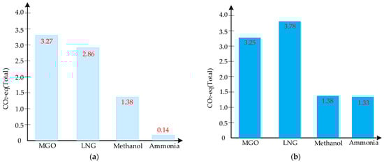
Figure 9.
Comparative diagram of greenhouse gas emissions for different fuels (CO2-eq (total)) from main (a) and auxiliary (b) engines [49].
As seen from Figure 9, when ammonia is used as fuel, it results in the lowest share of GHG emissions into the atmosphere from both main and auxiliary engines. The comparative characteristics of ammonia and diesel fuel for marine engines are presented in Table 11 [50].
Table 11.
Comparative characteristics of two fuels: ammonia and diesel [50].
The unfavorable physical properties of ammonia require solutions when using it as fuel for marine engines. The combustion characteristics of ammonia differ significantly from those of oil and most renewable fuels (Table 11). Its low number of cetane (5–7 units) and high autoignition temperature (650 °C) mean that ammonia can only ignite at a compression ratio of 35:1 or higher. Considering the geometric parameters of marine engines [50], this is not practical.
The compression ratio in diesel engines reaches up to 20:1. To ensure the combustion of ammonia in such engines, fuel with good autoignition properties (such as diesel or biodiesel) is required.
4.4.2. Features of Ammonia Production and Transportation
The production of ammonia for commercial purposes uses the Haber–Bosch process. In this process, hydrogen and nitrogen are combined at high temperatures using a catalyst [88]. Solar, wind, or hydro energy can be used in the production of green ammonia. This is an advantage of green ammonia production over HFO production [88]. One of the leading global ammonia producers, Yara, plans to build a demonstration facility for green ammonia synthesis using solar energy by 2025 [88]. This will enhance the competitiveness of green ammonia production.
Ammonia, like hydrogen, can be used as a supplementary fuel in diesel engines and gas turbines and as the primary fuel in fuel cells. This makes it attractive and competitive [88]. For land transportation, ammonia is transported via pipelines, while for water transportation, tankers are used [51].
4.4.3. Features of Ammonia Storage on Marine Vessels
Innovation and safety are crucial to mitigating the risks associated with using ammonia as marine fuel. The substance’s toxicity necessitates strict adherence to safety and occupational health regulations. Limited space and the absence of external assistance are challenges when installing and operating equipment on maritime vessels. A thorough risk assessment to identify potential leakage points and failure scenarios is necessary to ensure safety. Impact thresholds and alarm systems should be set regarding toxicity and flammability concentrations. To prevent prolonged and immediate exposure, the placement of gas detectors in hazardous areas is crucial. Safety measures are vital for operational security [52].
A significant issue in ammonia storage is corrosion, which creates both financial and safety risks. Liquid ammonia is stored at ambient temperatures around −33 °C under atmospheric pressure. Storage tanks for anhydrous ammonia are designed according to specific codes such as API 620 R or BS 7777 [52]. Standard materials for atmospheric ammonia tanks include certified low-temperature carbon manganese steel tested at temperatures close to −40 °C.
The susceptibility to crack formation due to corrosion increases under stress. The compatibility of the weld seam and the base material is crucial for resistance to crack formation under the influence of ammonia [52].
4.5. Biofuel
Biofuels are produced from organic raw materials. In the near future, they are considered one of the most competitive options for the rapid decarbonization of maritime transport. Biofuels, when blended, are compatible with conventional marine fuels. They can be used on existing vessels with minimal modifications or without any at all. Furthermore, existing bunkering infrastructure can be utilized [53].
4.5.1. Environmental Impact of Marine Engines Running on Biofuel
Depending on the raw materials used in production, biofuels are divided into four main generations. The first generation (1G) is produced from food crops and is widely used in the automotive sector. The competition for land with food production impacts the sustainability of 1G. Considering the life-cycle emissions from land-use changes (LUC), the environmental efficiency of 1G biofuels is questionable. Furthermore, to meet the demand for biofuels in shipping, vast areas of land are required.
Second-generation biofuel (2G) is produced from non-food biomass (lignocellulosic materials, waste, and residues). This fuel has significant potential for transportation because there are no food-versus-fuel disputes. However, the production of 2G biofuel still faces economic and technical challenges. As manufacturing technologies evolve, it is expected that by 2030, this type of fuel will penetrate the market significantly.
Third-generation (3G) biofuels are produced from algae. Algae are a rich resource. Compared to energy crops, this resource can theoretically yield oil 10 to 100 times more. At this stage, the low energy efficiency of the 3G system is a technological barrier to its viability. Genetically modified microorganisms and crops are used as feedstock in the production of fourth-generation (4G) biofuels. Currently, this biofuel is in the research phase [53]. In ref. [53], emission measurements were conducted accounting for voyage conditions and engine operating parameters. Considerable effort was made to perform emission measurements at engine loads closely aligned with those specified in ref [89].
The positions of the engine telegraph in the forward direction will determine five typical operating modes of the main engine: Mode 1—very slow, Mode 2—slow, Mode 3—half ahead, Mode 4—full ahead, and Mode 5—navigational full ahead. Two auxiliary diesel generators operated in all five modes of the main engines, while the third remained in reserve.
In all five engine operating modes, emissions were measured in increasing order for each fuel tested. Considering the weight coefficients recommended by ref. [89] for marine applications of type E2, the weight coefficients were established for each engine operating mode. The operation of the engine at loads exceeding 50% was assumed to have a weight coefficient of 85%.
In each mode, navigational data, engine parameters (engine power, speed, fuel consumption, etc.), and environmental conditions were monitored using ship’s instruments. Table 12 shows the corresponding weight coefficients for each of the five engine operating modes. Additionally, the registered engine operating conditions for various test fuels are presented. In the case of using a biofuel mixture, for each engine condition operating in Modes 2 and 4, two values are given [53]. These values, collected under similar engine operating conditions during the use of biofuel mixture, represent different emission samples.
Table 12.
Corresponding engine operating conditions for the tested biofuels [53].
Figure 10 shows the recorded data for each engine operation mode, navigation, and environmental conditions [53]. The red dashed line (Figure 10c,e) represents the NOx emission limits for Tier II. These values apply to bulk carriers operating with engine speeds below 130 rpm, specifically 14.4 g/kWh.
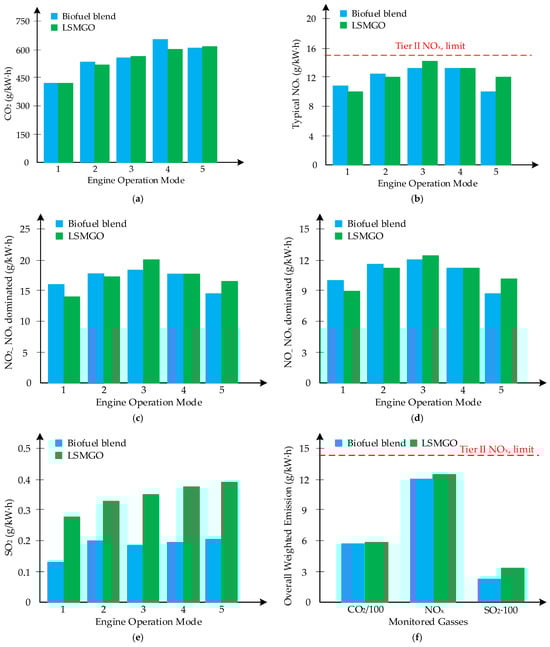
Figure 10.
Emission factors for the investigated fuel types [53]: (a)—dependence of CO2 emissions on engine operating modes; (b)—dependence of total NOx emissions on engine operating modes (data are provided for the typical contribution of NO and NO2 to total NOx emissions, 0.85 and 0.15, respectively); (c)—extreme scenario of total NOx emissions where NO2 emissions dominate per engine operating mode; (d)—extreme scenario of total NOx emissions where NO emissions dominate per engine operating mode; (e)—dependence of calculated SO2 emissions on engine operating modes; (f)―total weighted emissions of CO2, NOx, and SO2.
4.5.2. Features of Biofuel Manufacturing and Transportation
In discussions surrounding shipping sector decarbonization, numerous alternative energy sources are under consideration. The discourse frequently centers on ammonia (NH3), hydrogen (H2), natural gas (primarily CH4), and methanol (CH3OH). For short-term biofuel applications, there are several other alternatives [90]. Table 13 presents a comprehensive overview of these candidate fuels and their respective production technologies.
Table 13.
Renewable energy sources that can be used as fuel for maritime transportation and technologies for their production [90].
Biochemical reactions are processes facilitated by biocatalysts, such as microbial organisms, microbial communities, or enzymes. These reactions typically exhibit high feedstock specificity and occur under mild conditions, specifically at room temperature, atmospheric pressure, and neutral pH. Liquefied biogas (LBG) and ethanol have proven to be the most viable biofuel types for the maritime sector [90].
Thermochemical processes represent production pathways that rely on decomposition effects induced by heat and pressure. These processes effectively simulate the natural mechanisms of fossil oil and gas generation from biomass. Natural generation mechanisms took place over millions of years.
In contrast, thermochemical processes occur over the span of seconds or minutes. The primary biomass components—cellulose, hemicellulose, and lignin—undergo decomposition and depolymerization into oligomers. Oligomers can either break down into smaller molecules or re-polymerize into long chains of hydrocarbons or fatty acids [90].
In general, raw materials can be divided into four groups: (i) (poly)saccharides, (ii) oils and fats, (iii) lignocellulose, and (iv) lignin. These can be classified into the following biomass groups [90]:
- Carbohydrate crops.
- Oil crops.
- Lignocellulosic biomass.
- Woody biomass.
- Algal biomass, as well as residues from their production and processing.
Marine algal biomass is particularly interesting due to its abundance and the fact that it does not occupy arable land. The processing of marine algae is complex. It faces numerous challenges in industrial applications, making algae processing an impractical solution for the fuel sector at present [43,44]. Given that this study focuses on short-term solutions for biofuels, algae were excluded from further consideration in the raw material analysis.
The waste generated from harvesting or other production processes can be used to produce biofuels. This makes a significant contribution to the circular economy and sustainable development. Thus, the European Renewable Energy Directive incentivizes the use of waste for bioenergy by introducing emission savings multipliers for biomass derived from waste [90].
One of the frequently mentioned challenges in biofuel production is the security of supply, logistics, and transportation of biomass. The supply of biomass fundamentally differs from the continuous extraction of fossil oil [90]. Harvesting is seasonal and can vary significantly month by month. Biorefineries may face downtime during the off-season, which heavily impacts their economics.
For the economic efficiency and quality of the produced biofuel, the transportation of biomass is a critical factor. For example, in the Netherlands, wood pellets are not produced in sufficient quantities, and even dried and compressed biomass degrades over time [90].
This becomes problematic when biomass must be imported from abroad, which can take 6–9 weeks or more. The study [90] also emphasizes the challenges arising from this. High-quality biomass may be purchased at a high price, but instead a partially degraded product might be received for which the bioprocess is not optimized.
4.5.3. Features of Biofuel Storage on Marine Vessels
Table 14 presents the energy characteristics of the studied types of biofuels and their fossil fuel equivalents [90]. From Table 14, it is evident that despite its moderate calorific value, HFO has the highest energy density. This is because its gravimetric density is close to that of water. All other oils are significantly lighter. This factor leads to an increased frequency of refueling.
Table 14.
Energy performance of marine biofuels and their fossil counterparts [90].
LBG/LNG has the lowest calorific value and energy density. Cryogenic storage is required for LBG/LNG, which is difficult to implement in ship hulls. This is because storing LBG/LNG requires sacrificing a significant amount of cargo space. When transporting LBG/LNG, part of the cargo can be used as fuel. Currently, this is the most common and economically efficient use of LNG in maritime shipping.
As seen in Table 14, LBG, biomethanol, and bioethanol have the lowest energy density (21, 16, and 27 MJ/L, respectively). The energy density of other biofuels ranges from 33 MJ/L (HVO) to 36 MJ/L (UPO). This implies an increase in refueling frequency by 15–8% compared to HFO.
These percentages assume that the tank volume is a limiting factor. Slow and slow steam and arrival at port on time are measures to improve efficiency. They can result in significant fuel savings, which may help balance fuel requirements.
4.6. The Techno-Economic Analysis of Alternative Fuels for Marine Vessels
4.6.1. Analysis of Technologies
Single-fuel and dual-fuel internal combustion engines (ICEs), as well as fuel cells (FC), are the main installations for fuel use in the maritime sector. Fuel cells are electrochemical devices that convert chemical energy from gaseous fuels into electrical energy. The high energy conversion efficiency and low emissions are unique advantages of this technology compared to combustion technologies [91].
The classification of fuel cells (FC) is based on the selection of the electrolyte and fuel. Currently, the following types of fuel cells are available:
- PEMFCs—Proton Exchange Membrane Fuel Cells.
- AFCs—Alkaline Fuel Cells.
- PAFCs—Phosphoric Acid Fuel Cells.
- MCFCs—Molten Carbonate Fuel Cells.
- SOFCs—Solid Oxide Fuel Cells.
- DMFCs—Direct Methanol Fuel Cells [92,93].
From the perspective of availability, efficiency, and technological maturity for onboard power generation, PEMFC and MCFC are the most promising types of fuel cells. Additionally, for medium- and long-range vessels, SOFCs are considered the most promising due to their potential.
Table A1 (Appendix A) presents the characteristics of alternative fuels used in maritime vessels. The data in Table A1 are sourced from [91].
4.6.2. Economic Performance Analysis
The commercial viability of alternative fuels plays a crucial role in determining the level of their deployment. Table A2 presents a cost analysis of selected alternative fuels based on different production pathways. The average price of Marine Gas Oil (MGO) at 20 global ports from 2018 to 2021 was used as a benchmark for comparison. Relative costs are compared based on the metric of USD/MJ of energy content. The data in Table A3 are sourced from [91].
Table A3 combines the costs of building and acquiring engine installations with the costs of onboard fuel storage systems. Based on the listed costs, the total capital expenditures for the ship’s engine installation systems and fuel storage systems using alternative fuels are determined.
From the analysis of Table A1, Table A2 and Table A3, it follows that hydrogen, when used as a fuel for Otto cycle engines, can be consumed in spark ignition engines and in various types of dual-fuel engines. Hydrogen-powered marine engine systems are not yet widely adopted. The cost of such systems is comparable to that of LNG/LBG-based systems.
Diesel engine systems using methanol are well established, with low modernization costs. Conversion from conventional systems to methanol/dual-fuel systems achieves similar or even higher efficiency [94].
Ammonia-based diesel engines are a relatively new concept in the maritime sector. Large ammonia engines used in marine vessels have not yet been commercialized.
The main barriers to the adoption of fuel cell (FC) technology in the maritime sector are high capital investments and relatively short, expected service life. The cost analysis of FC systems shows that, with increased production volumes, the costs of such systems tend to decrease [95].
One of the main issues for the broader use of hydrogen in the maritime sector is its storage. Releasing hydrogen from chemical storage requires higher energy or higher temperature. As a result, the general trend in hydrogen storage technologies is that hydrogen is less accessible in chemical storage than in physical storage [96].
LNG and LBG have low volumetric density. Therefore, LNG and LBG are stored on board in specially designed energy storage systems to keep them in a liquid state. In addition to membrane tanks for marine use, the IMO has defined three main types of tanks (Types A, B, and C).
For the storage of large volumes of LNG and LBG, Type A, B, and membrane tanks, which are not pressurized, are used. In smaller vessels, Type C pressurized tanks are commonly used because of their smaller capacity and the absence of the need for a secondary barrier and boil-off gas processing system.
5. Innovative Approaches and Challenges of Using Solar Energy in Shipping
Another alternative power source for ship engines is electricity. Unlike the alternative energy sources discussed in Section 4, electricity eliminates several issues associated with transportation when used to power ship engines. Additionally, the use of electricity results in no greenhouse gas emissions into the atmosphere. Solar energy, wind energy, and wave energy can be primary sources of electrical power [97].
Since the use of wave energy as a source of electricity is still poorly studied, this primary source of energy will not be considered in further analysis. Wind energy will also not be considered as a primary source of electricity due to the following factors:
- Integrating wind turbines on large cargo ships requires massive turbines and significant space for installation and energy storage [98].
- Wind gusts cause fluctuations in the engine power supply, which necessitates additional measures to stabilize the voltage, leading to increased costs [99].
5.1. Components of Solar-Powered Marine Vessels
The inclusion of fuel cells in hybrid engines is an innovative approach to improving the reliability of solar-powered ships. The chemical reaction between oxygen and hydrogen is the basis for generating electricity through fuel cells. Fuel cells, in combination with solar panels and/or wind turbines, can be used to power ship engines.
This combination of energy sources can offer increased efficiency, reduced emissions, and greater reliability compared to a system that relies solely on solar or wind energy [100,101,102]. Figure 11 shows a structural diagram of such a system.
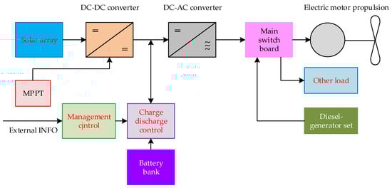
Figure 11.
Topology of a hybrid photovoltaic–diesel system [93].
The photovoltaic battery, the DC–DC converter, Power Point Tracking (PPT), the electric motor, and the battery management system constitute the structural components of the hybrid photovoltaic–diesel system for a marine vessel (Figure 11). This system incorporates elements such as a photovoltaic module, a DC–DC converter, Maximum Power Point Tracking (MPPT), a battery along with its charge-discharge controllers, a diesel generator, an inverter, and a connector.
Another type of vessel that operates on solar power is a vessel entirely dependent on solar photovoltaic energy as the sole source for meeting the onboard load demand. This design is intended for small vessels. The power supply in such vessels is required for operating the electric motor for propulsion and for minor loads, such as lighting.
Such a watercraft simply requires power to operate the electric motor for propulsion and small loads, such as lighting. In these types of boats, PV is the only sufficient energy source to serve all purposes on a small scale. The only difference between the two topologies is the presence of a diesel engine in the hybrid system. All other components for both types of boats are the same, with slight differences in their component ratings, as this vessel caters to low loads. A 30-foot vessel typically requires 300–350 W of power on average, primarily depending on energy consumption and boat size [100].
5.1.1. PV Array
The limited space available for installing photovoltaic (PV) cells on a vessel is a major challenge when using solar energy as the primary energy source. The placement of PV modules should be optimized to absorb the maximum amount of sunlight. A photovoltaic battery, or solar battery, is an assembly of various solar modules. The output energy generated by a photovoltaic battery depends on the intensity of sunlight absorbed by its elements [103].
Utilizing equipment to convert solar energy into power for the marine vessel’s engines poses stability challenges due to the load on the vessel. Another issue is partial shading, which affects the PV system’s performance under different weather conditions [103].
The absence of energy production costs, the universality of the installation, energy generation aligning with peak demand, and cost savings are significant technological advantages of solar PV systems [104].
The cost of solar-powered ships will be higher than that of diesel-powered vessels, but their operating expenses will be lower. Additionally, solar-powered ships use environmentally friendly fuel, making them a promising long-term option [105].
5.1.2. DC–DC Converter as a Power Stabilizer
A power stabilizer is a crucial component that enhances system efficiency. It regulates the power output of the photovoltaic (PV) system and increases its yield when connected to the Maximum Power Point Tracking (MPPT) system.
Power stabilizers used in PV systems are DC–DC converters. Step-down (buck), step-up (boost), and step-down/step-up (buck–boost) converters are commonly used in PV systems. The boost converter is primarily used due to its high-power capability. Unlike a step-up converter, in a step-down converter, the output voltage can be lower than the input voltage. In a step-up converter, the output voltage is higher than the input voltage. In a buck–boost converter, the output voltage can be either higher or lower than the input voltage.
By means of sequential conversion of the maximum available solar energy, even under harsh weather conditions, a high efficiency of the photovoltaic generator (PVG) can be achieved [106]. A step-down converter is used for this purpose. It extracts the maximum energy from the photovoltaic source to meet the load requirements [107].
5.1.3. PV MPPT
MPPT (Maximum Power Point Tracking) is designed to increase the output power of the photovoltaic (PV) battery regardless of weather conditions. The application of MPPT allows achieving the maximum power of photovoltaic panels at different levels of solar radiation, irrespective of weather conditions. Various MPPT algorithms are used to regulate the operating cycle of the DC–DC converter [108]. MPPT methods play a crucial role in enhancing electricity production using solar cells [105].
5.1.4. Electric Motor
In [109], it is shown that the mass and size characteristics, along with lower cost, are the main advantages of the alternating current (AC) motor compared to the direct current (DC) motor. Therefore, the use of an AC motor is preferred as the main engine.
5.1.5. Battery Management System
The battery is located onboard the vessel. Solar radiation depends on the time of day and weather conditions. On sunny days, the output energy from the solar panels is higher. Therefore, solar energy cannot always meet the load requirements. The onboard battery is designed to support the continuous supply of power to the load. If the electric motor stops due to insufficient sunlight for the solar PV panels to generate energy, the battery serves as a backup. To enhance battery efficiency and lifespan, a good battery management system (BMS) is required. Lithium-ion batteries are currently the most preferred due to their long lifespan, high energy density, and environmental friendliness [110]. Internal operating parameters, such as current, voltage, and temperature, are monitored and managed by the battery management system (BMS) during charging and discharging. To enhance safety and performance, the BMS evaluates the State of Charge (SOC) and State of Health (SOH) [111]. To prevent overcharging and sudden explosions, the BMS maintains the charge level within specified limits.
5.2. The Application of Concentrated Solar Energy Systems on Marine Vessels
A promising direction for scientific research is the use of concentrated solar energy systems (CSPs) on ships. In this technology, mirrors or lenses are used to concentrate sunlight on a small focal point. This creates high temperatures, which can be used to produce steam and subsequently generate electricity.
Although CSP systems are not yet widely used on ships, their efficiency has been demonstrated in land-based applications. This technology holds significant potential for future deployment on large marine vessels. The adaptability of CSP technologies, combined with solar energy, can lead to innovative and sustainable energy solutions for marine applications, overcoming some limitations associated with traditional photovoltaic systems [109].
CSP systems include key types of technologies such as parabolic trough collectors (PTCs), linear Fresnel reflectors (LFRs), solar dishes (SDs), and solar towers (STs) (Figure 12) [102]. Figure 13 shows the main categories of CSP configurations, such as linear-focusing and point-focusing [100].
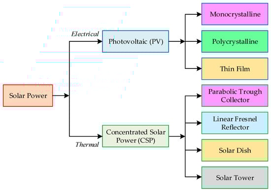
Figure 12.
Leading technologies for solar energy integration [109].


Figure 13.
The four main types of CSP technologies: (a)—parabolic trough collector; (b)—linear Fresnel reflector; (c)—solar dish; (d)—solar tower [107].
All CSP technologies share the same fundamental concept but have different implementations and processes. The primary components of CSP systems are reflectors, receivers, Heat Transfer Fluid (HTF), and the associated cooling system [54].
Solar energy is concentrated on a receiver. The receiver then converts this energy into heat with the help of heliostats or controlled mirrors. Lenses or mirrors are used as reflectors to focus sunlight into a narrow beam and direct it onto the receiver. To generate electricity, mechanical energy is converted into turbine energy. This is performed using steam, which is produced by heating the Heat Transfer Fluid (HTF) and circulating it through the receiver.
The Thermal Energy Storage (TES) in CSP systems is required for storing thermal energy before it is converted into electricity. Due to its storage capability, CSP serves as a versatile renewable energy source.
To ensure continuous and reliable power supply over extended periods, TES must be integrated into the solar thermal power plant. Currently, TES is used as storage for both sensible and latent heat, as well as thermochemical storage with minimal volume and the highest energy density [112].
Figure 14 illustrates the operational diagram of an advanced solar power plant, which utilizes CSP for electricity generation [112]. This system is based on the use of a dense suspension of HTF particles. The application of highly efficient electricity generation cycles in this system uses the dense suspension of HTF particles, allowing the receiver to operate at high temperatures (above 650 °C).
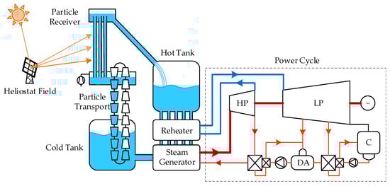
Figure 14.
Schematic diagram of an advanced CSP technology for electricity generation from heat [111].
The efficiency of thermal conversion is improved by this supercritical Rankine cycle power block, increasing from 39.9% to 45.4%, which leads to a reduction in the heliostat field area by 9.6%. The study [111] notes that increasing the operating temperature range by 24.5% results in a 12.5% increase in storage density and a 22.5% reduction in overall storage capacity. The lack of heating also leads to a decrease in parasitic energy consumption. Overall, a reduction in electricity costs of approximately 10.8% is expected due to improved cycle efficiency, increased storage density, and the overall reduction in parasitic energy consumption [111].
5.3. Contrasting PV and CSP
CSP and PV panels are leading technologies in solar energy. Monocrystalline PV panels have high power and efficiency, which is why they are widely used. Due to their availability in higher power modules (over 300 W), they generate more energy compared to other types of panels [113]. Unlike CSP, PV instantly converts light into electricity. Solar cells absorb light, generating direct current, which is then converted into alternating current by inverters and supplied to the electrical grid. An effective method for utilizing solar energy through PV technology is proposed in ref. [113], involving the conversion of direct or diffuse sunlight into electricity. In ref. [113], the results of a comparison of the overall performance of monocrystalline and polycrystalline solar modules over the course of a year are presented. The comparison showed that the monocrystalline module has higher maximum efficiency and total specific output energy.
The type of technology used the light spectrum, solar radiation, ambient temperature, humidity, and wind were considered when evaluating PV modules [114]. In [115], it was assumed that, in addition to the mentioned factors, climatic and environmental factors also influence the wear and aging of solar modules. Table A4 presents the results of a comparison of other characteristics of PV and CSP.
5.4. Techno-Economic Analysis of the Use of Battery Storage Systems for Powering Marine Vessel Engines
Vessel propulsion systems powered by battery storage are more energy-efficient than internal combustion engines (ICEs) and fuel cells (FCs) [116]. To store solar energy on board, battery types such as lithium iron phosphate (LPF) or lithium nickel manganese cobalt (NMC) batteries, which have higher capacity, can be used. Due to the low volumetric density of battery systems, this technology is not suitable for long-distance vessels. Table 15 presents the costs of constructing and acquiring propulsion systems, along with the costs for on-board energy storage systems.
Table 15.
Costs of construction, acquisition of propulsion systems, and costs of on-board energy storage systems [91].
Battery systems have economic drawbacks related to high capital costs. They are expensive components. When applied on marine vessels, their high cost is explained by the stricter requirements for insulation, cooling of equipment, and additional fire safety measures.
Currently, battery systems are only available for small coastal vessels. On long-range ships, battery systems can be applied as part of a hybrid power system. In such systems, the electric motor receives power partially from a diesel generator running on liquid fuel and partially from the battery.
6. Emerging Trends in Solar Energy for Maritime Transport
6.1. Analysis of the Limitations for the Use of Solar Energy on Marine Vessels
Despite the benefits of solar energy, several challenges and limitations remain. The low conversion efficiency of PV cells is a key problem in their application in maritime transportation. The low efficiency can result in insufficient energy production for the engine system, particularly under unfavorable weather conditions or periods of reduced sunlight. Improving the efficiency of PV cells is considered critical to addressing this limitation [34].
Another disadvantage is the significant deck or roof area required for the installation of a sufficient number of solar panels. To generate substantial electrical power, ample space must be allocated for a large-scale deployment of solar arrays. The availability of adequate surface area is a practical limitation, and shipbuilders must carefully plan the integration of solar panels into the vessel’s design.
Cost is also a critical factor. While solar energy itself is free, the production of high-quality solar cells remains expensive. The cost of a PV system constitutes a significant portion of the initial capital investment for shipbuilders. Achieving a balance between long-term economic benefits and the upfront costs of installing solar panels presents a challenging decision for ship owners [34,117].
The harsh conditions of the marine environment pose additional challenges for the durability of photovoltaic cells. Factors such as vibration, temperature fluctuations, hail, and corrosion caused by salt or humidity can affect the performance of solar panels. Although many solar panels aboard vessels are equipped with tempered glass and atmospheric and salt-resistant protective coatings, they remain susceptible to contamination, discoloration, corrosion, and wear due to prolonged exposure to temperature variations, high salinity, and humidity. Reliable design practices and maintenance procedures are crucial to mitigating these issues and ensuring the long-term efficiency of solar energy systems on ships.
6.2. Trends in the Development of Solar Energy for Marine Transportation
The emerging trends in the utilization of solar energy for maritime transport focus on integrating advanced technologies to enhance resilience and efficiency within the sector. Key directions include the development of hybrid systems that combine solar energy with sources such as wind and hydrogen fuel cells. This combination aims to reduce greenhouse gas emissions and dependence on fossil fuels. The maritime industry stands on the brink of revolutionary changes in embracing solar energy.
A critical success factor will be improving the efficiency of PV cells. The current limitations in the efficiency of solar panels are one of the main obstacles to their widespread use on ships. Future research should concentrate on the development of new materials and designs capable of significantly increasing energy production per unit of surface area. This is particularly important given the limited space available on ships [118].
The development of hybrid systems represents another promising direction. Combining solar energy with other energy sources, such as fuel cells, wind turbines, and traditional diesel engines, will create more reliable and efficient energy systems. In the future, we can expect the emergence of more advanced hybrid systems capable of optimally utilizing different energy sources depending on the operating conditions of the vessel.
The maritime industry is also exploring the use of solar energy in conjunction with energy storage systems, such as batteries. This enables vessels to store excess energy produced during the day for use at night or during periods of low sunlight. Furthermore, advances in solar technologies, such as more efficient solar cells and lightweight, flexible panels, are making the use of solar energy on maritime vessels more feasible [77,119].
The integration of Carbon Capture, Utilization, and Storage (CCUS) technologies with solar systems opens new avenues in the fight against greenhouse gas emissions. Further development of these technologies could lead to the creation of ships with nearly zero carbon footprints. Particularly promising is the approach of converting captured CO2 into synthetic fuel or other valuable products, which could enhance the economic efficiency and autonomy of vessels.
The adaptation of concentrated solar power (CSP) systems for marine applications represents a promising avenue for future research, with new practical applications in the maritime sector. Although CSP technology is not yet widely used on ships, its ability to generate high-temperature heat addresses specific needs in maritime operations. For example, CSP systems can be effectively utilized in desalination processes on ships, particularly in Multi-Effect Distillation (MED) systems, which require temperatures of 70–80 °C. This capability is critical for long voyages where freshwater production is essential and often energy intensive [120].
Moreover, the high-temperature heat generated by CSP systems can be used for absorption cooling systems in cargo holds and living spaces, potentially reducing the load on electrical systems on ships. On large vessels with adequate space for solar collectors, CSP technology could assist in electricity generation via Organic Rankine Cycle (ORC) systems, although this application requires further development for marine use.
These CSP applications in the maritime context align with real operational needs, offering potential improvements in energy efficiency and reducing reliance on conventional fuel sources. However, the implementation of CSP on ships faces challenges, including spatial constraints and the necessity to stabilize the system in dynamic marine environments. These challenges are active areas of current research and development in the field of marine solar energy applications.
An important area of focus will be the development of materials and designs for solar panels specifically adapted to marine conditions. Durability against corrosion, vibration, extreme temperatures, and mechanical damage is crucial for the long-term effectiveness of solar systems on vessels. Innovative solutions in this area will significantly expand the use of solar technologies in the maritime industry [121].
However, issues remain, including the necessity for substantial initial investments and the development of reliable infrastructure to support these technologies [122]. Reducing the costs of manufacturing and installing solar systems, as well as developing more efficient methods of integrating them into ship designs, will make this technology more attractive to ship owners. Additionally, it is important to develop methods for assessing the long-term economic benefits of using solar energy on ships [123,124].
The design of new types of vessels specifically developed for the maximum efficient use of solar energy could become a breakthrough direction. This may include innovative hull shapes optimized for the placement of solar panels or new concepts for the layout of decks and superstructures.
Finally, the development of a regulatory framework and international standards for the use of solar energy on ships will play a critical role in stimulating innovation and ensuring safety. Establishing clear guidelines and incentives for the adoption of solar technologies can significantly accelerate their acceptance within the maritime industry [125,126,127].
The future of solar energy in shipping appears promising. A combination of technological innovations, economic optimization, and legal frameworks could lead to the widespread adoption of solar technologies across various types of vessels. This would not only reduce the carbon footprint of the maritime sector but also provide new opportunities to enhance vessel efficiency and autonomy [128].
7. Discussion
This study compares alternative energy sources for marine vessels based on criteria such as greenhouse gas emissions, production, transportation, and storage challenges. The comparison was conducted for various alternative fuels: LNG, methanol, hydrogen, ammonia, and biofuels. The analysis revealed that using hydrogen as a fuel results in no greenhouse gas emissions. However, issues arise in hydrogen transportation, such as determining the mixing ratio of hydrogen, which is a systematic challenge due to various factors: natural gas composition, pipeline material, hydraulic conditions, equipment service life, environmental impact, and variations in client-specific end equipment [85]. Furthermore, when storing hydrogen on board vessels, factors such as the following should be considered:
- Hydrogen is a highly flammable fuel.
- Risks of hydrogen leaks through joints and cracks in any pipelines or storage system.
- Hydrogen disperses easily in the air.
- In high concentrations, hydrogen can displace oxygen in the air, leading to asphyxiation.
- The necessity to avoid explosion risks [85].
- The necessity of appropriate materials capable of withstanding low temperatures to prevent brittleness.
- The necessity to prevent liquid hydrogen spills to avoid asphyxiation and explosion.
Another potential energy source for powering marine vessel engines is solar energy. When the engines are powered by electricity generated through the conversion of solar energy, as in the case of hydrogen fuel, there are no greenhouse gas emissions. However, providing the necessary electrical energy to the engines is only feasible for smaller vessels [100]. Current solar energy conversion technologies do not allow for the complete powering of main engines with electrical energy [100]. For larger vessels, either a hybrid PV–diesel power system or concentrated solar power (CSP) systems are employed, with the structural configurations depicted in Figure 11 and Figure 14, respectively. The benefits and drawbacks of PV and CSP systems are summarized in Table 15.
The main drawback of PV systems is their intermittency, which makes energy storage challenging as batteries are economically unfeasible for large-scale installations. Hybrid power systems are increasingly used in other forms of transportation, particularly in rail transport [129,130]. The issues encountered in hybrid power systems for rail transport are also relevant to marine applications. Specifically, these involve the optimization of energy flow algorithms from the PV system and the diesel engine to the main engine.
In [90], it is noted that field-oriented control (FOC) is used to manage the main engines of marine vessels with hybrid PV–diesel power. Studies in [131,132] show that both FOC and direct torque control (DTC) can be applied for managing the induction motors used as main engines on marine vessels. The comparison of the advantages and disadvantages of FOC and DTC is presented in Table A5.
The analysis of the advantages and disadvantages of the two control systems, presented in Table A5, predetermines their effectiveness for use on ships of different types. For vessels where frequent changes in movement parameters are characteristic, DTC is more efficient. This is since when the vessel stops in an FOC system, power is supplied to the main engine, but the engine does not perform useful work. This operating mode is necessary to prevent the main engine from exiting saturation mode. As a result, the energy efficiency of the propulsion system with FOC is reduced. DTC does not have this disadvantage.
Moreover, the use of DTC is more effective on large cargo vessels. This is because, for such vessels, the quality of torque control is a more important criterion. In contrast to cargo vessels, passenger ships operate at higher speeds. Additionally, the engine shaft speed may exceed the nominal value. For such vessels, FOC is more efficient because, in these modes, it demonstrates better speed control performance.
Another significant issue in the traction systems of marine vessels with hybrid PV–diesel power is the presence of an inverter (Figure 11). Technically, the inverter can be implemented using electronic switches, typically IGBTs (Insulated Gate Bipolar Transistors) and, less frequently, GTOs (Gate Turn-Off Thyristors). Pulse-width modulation (PWM) is used as the control law for the electronic switches. A key parameter of PWM is the sampling frequency. Since the main engines of marine vessels are high-power asynchronous motors, the values of the phase stator currents and voltages are substantial.
In other words, the electronic switches of the inverter must operate with high voltages and currents. This results in the fact that the high-power electronic switches have a limited sampling frequency, typically in the range of hundreds of Hertz. The consequence of this low sampling frequency is the presence of significant higher harmonics in the stator currents. This leads to increased losses in the electrical circuits of the traction system and, consequently, higher energy consumption [131,132]. Furthermore, the presence of higher harmonic components results in torque pulsations on the motor shaft—the higher the level of harmonics, the greater the torque ripple on the motor shaft.
To eliminate higher harmonic components in the spectra of phase currents of the induction motor stator, compensation devices should be used [133,134,135]. When compensating for higher harmonics, both frequency-domain and time-domain filtering can be used [134]. A comparison of the advantages and disadvantages of harmonic compensation systems with filtering in the frequency and time domains is presented in Table A6.
The use of harmonic compensation devices will complicate the propulsion system of the ship but will enhance its energy efficiency [134]. Moreover, while the hybrid PV–diesel system reduces greenhouse gas emissions to some extent, the issue of greenhouse gases is not fully resolved since the diesel is powered by fossil fuels.
CSP can supply electricity even at night, making it dispatchable and increasing its integration into the energy sectors. Moreover, CSP generates alternating current, thus eliminating the need for an inverter (Figure 13). As a result, this technology avoids the issues associated with inverters, as discussed earlier. Additionally, since CSP fully supplies the main engine with electrical energy, it resolves the problem of greenhouse gas emissions.
However, CSP has several drawbacks, the main one being that CSP relies solely on Direct Normal Irradiance (DNI), which fluctuates between 65% and 85% of the total global horizontal irradiance (GHI). Furthermore, the use of a steam turbine and energy systems (Figure 14) increases the mass and size of the system, which is critical for marine applications.
The adaptation of concentrated solar power (CSP) systems for marine applications represents one of the promising directions for future research, with new practical applications in the maritime sector.
Another important research direction is the development of materials and designs for solar panels specifically tailored to marine conditions []. The increase in the number of ships using solar energy requires advanced batteries. An analysis of the advantages of battery systems that may be used in maritime transport in the future is provided in Table A7.
The development of methods for evaluating the long-term economic benefits of using solar energy on ships [120,121] and the establishment of regulatory frameworks and international standards for solar energy use on vessels [129,131] are also crucial areas for future studies.
Additionally, for hybrid PV–diesel power systems, prospective research directions could include work on implementing DTC (direct torque control) instead of vector control systems, as well as efforts to mitigate higher harmonics in the phase current spectra of induction motors.
8. Conclusions
This study provides an overview of the existing types of alternative energy sources used in marine vessels and offers recommendations to improve the solar energy technologies in ships. The analysis of alternative fuels used on marine vessels is based on the following criteria: greenhouse gas emissions, production and transportation characteristics, onboard storage requirements, and technoeconomic indicators.
It has been established that when hydrogen is used as a fuel, no greenhouse gas emissions are released into the atmosphere. However, there are challenges associated with the transportation and storage of hydrogen onboard ships. These challenges are related to its destructive impact on the materials of supply and storage systems, as well as its flammability and explosiveness. Furthermore, the use of hydrogen as fuel in marine vessels requires the highest investment.
The lowest investment is required when LNG, produced from natural gas, is used as fuel, but this fuel is characterized by a relatively high level of greenhouse gas emissions.
As a result of the analysis conducted, it was found that the use of solar energy would eliminate the problems related to transportation. Two technologies were considered: hybrid photovoltaic–diesel power systems and concentrated solar power (CSP) systems. It was discovered that the PV–diesel hybrid system utilizes global horizontal irradiance (GHI) and can operate under diffuse light. However, this system generates electricity instantaneously, making energy storage challenging, and batteries are economically unfeasible for large-scale installations.
Intermittency remains the primary disadvantage of photovoltaic. Moreover, in this system, direct current (DC) must be converted into alternating current (AC) using inverters, which also requires a reduction in higher harmonics in the main engine’s stator currents. This system only partially addresses the issue of greenhouse gas emissions.
The use of CSP allows for a continuous supply of electricity even at night, making it dispatchable. Moreover, CSP generates alternating current (AC), eliminating the need for inverters and, consequently, avoiding the associated issues. Additionally, CSP fully powers the main engine, effectively addressing the problem of greenhouse gas emissions. However, the use of steam turbines and energy systems leads to an increase in the mass and size of the system, which creates challenges for marine applications.
Trends in solar energy for maritime transport have been analyzed, such as the following:
- The adaptation of concentrated solar power (CSP) systems for marine applications.
- The development of materials and designs for solar panels is specifically intended for the marine environment.
- The development of methods for evaluating the long-term economic benefits of using solar energy on ships.
- The improvement of regulatory frameworks and international standards for the application of solar energy on ships.
Future research directions for the use of solar energy in the maritime sector have been proposed. Promising research areas for hybrid photovoltaic and diesel power systems include studies on the implementation of direct torque control (DTC) instead of field-oriented control (FOC), as well as efforts aimed at compensating higher harmonics in the stator current spectra of asynchronous motors. This will help improve the efficiency of the propulsion system.
Additionally, promising research directions may include studies focused on exploring the potential use of energy generated by the electric motor during the deceleration of the vessel. For ships with hybrid propulsion systems, research related to the synchronization of energy usage from various sources is of particular interest.
Author Contributions
Conceptualization, O.P., M.L. and S.G.; methodology, O.P., M.L. and S.G.; software, V.L.; validation, O.P., M.L. and S.G.; formal analysis, O.P., M.L. and S.G.; investigation, O.P., M.L. and S.G.; resources, V.L.; data curation, O.P., M.L. and S.G.; writing—original draft preparation, O.P., M.L. and S.G.; writing—review and editing, O.P., M.L., S.G. and V.L.; visualization, V.L. All authors have read and agreed to the published version of the manuscript.
Funding
This research received no external funding.
Institutional Review Board Statement
Not applicable.
Informed Consent Statement
Not applicable.
Data Availability Statement
Not applicable.
Conflicts of Interest
The authors declare no conflicts of interest.
Appendix A
Table A1.
Overview of the characteristics of alternative marine fuels in use [91].
Table A1.
Overview of the characteristics of alternative marine fuels in use [91].
| Type of Fuel | Calorific Value (MJ/kg) | Onboard Storage Requirements | Utilization Efficiency | Byproduct of Utilization | Availability of Commercial Utilization Technologies | |
|---|---|---|---|---|---|---|
| FC (Electrical Efficiency) | ICE (Internal Combustion Engine) | |||||
| Liquefied Natural Gas (LNG) | 50–55 | 163° (under pressure or without pressure) | 45–60% (SOFC) 35–45% (PEMFC) | 35–40% | CO2, H2O, NOx (ICE) | ICE: Yes, widely available for commercial use; FC: Underdeveloped, no commercial maritime use |
| Hydrogen | 120–140 | 350–700 bar (gaseous), −252.8 °C (liquefied), material-based storage | 50–60% (PEFMC/SOFC) | 30–35% | H2O, NOx (ICE) | ICE: Yes, available for commercial use; FC: Yes, available for commercial use |
| Ammonia | 22.5 | 21 °C below 8.8 bar or 33 °C at atmospheric pressure | 30–60% (SOFC) 15–30% (AFC) | 35–40% | H2O, N2, NOx (ICE) | ICE: Underdeveloped; FC: Underdeveloped, no commercial maritime use |
| Methanol | 22.7 | Liquid at ambient temperature | 30–50% (SOFC) 20–30% (DFMC) | 40% | CO2, H2O, CO (ICE), NOx (ICE) | ICE: Yes, widely available for commercial use; FC: Underdeveloped, no commercial maritime use |
| Biodiesel | 38–46 | Liquid at ambient temperature | 10–30% (AFC) | 10–30% (AFC), Varies | CO2, H2O, CO (ICE), NOx (ICE) | ICE: Yes, widely available for commercial use; FC: Underdeveloped, no commercial maritime use |
| Electricity | - | High energy density battery systems such as NMC, LFP, NCA, and solid-state batteries | - | - | - | Currently available only for small shore-based vessels |
Table A2.
Cost analysis of selected alternative fuels by different production pathways [91].
Table A2.
Cost analysis of selected alternative fuels by different production pathways [91].
| Fuel | Material for Fuel Production | Fuel Production Costs/Import Price, USD/MJ | Fossil Fuel Price, USD/MJ | Total Price |
|---|---|---|---|---|
| LNG | Natural gas | 0.0022–0.0092 | 0.014 | 0.16–0.66 |
| LBG | Biomass | 0.0081–0.032 | 0.57–2.29 | |
| Biodiesel | Soybean, palm oil, rapeseed | 0.013–0.027 | 0.92–1.93 | |
| Methanol | Biomass | 0.021–0.037 | 1.50–2.64 | |
| Methanol | Natural gas | 0.006–0.022 | 0.43–1.57 | |
| Hydrogen SMR | Wind power, water | 0.0063–0.035 | 0.45–2.5 | |
| Hydrogen electrolysis | Wind power, water | 0.025–0.08 | 1.78–5.71 | |
| Hydrogen electrolysis | Nuclear energy, water | 0.019–0.045 | 1.36–3.21 | |
| Ammonia | Natural gas | 0.0093–0.036 | 0.66–2.57 | |
| Ammonia | Wind power | 0.021–0.037 | 1.50–2.64 |
Table A3.
Construction costs, propulsion system acquisition costs, and on-board fuel storage system costs [91].
Table A3.
Construction costs, propulsion system acquisition costs, and on-board fuel storage system costs [91].
| Component | Capital Investments for Vessel Modernization, USD/kW | Capital Expenditures for Construction of New Vessels (Four-Stroke Engine/Two-Stroke Engine), USD/kW | Life Cycle |
|---|---|---|---|
| Propulsion system | |||
| ICE diesel, biodiesel | - | 240/460 | 30 years |
| ICE, methanol | 328 | 265/505 | 30 years |
| ICE, ammonia | - | 370/600 | 30 years |
| ICE, LNG, LBG, hydrogen | 900 | 387/850 | 30 years |
| Fuel cell, SOFC | - | 4000–9000 | 7–12 years |
| Fuel cell, PEMFC | - | 730–2860 | 7–12 years |
| Electrical and generator, LNG, LBG, hydrogen | - | 400 | 30 years |
| Electric motor | - | 250 | 30 years |
| Fuel storage system | |||
| Gas supply system + tank, LNG, LBG, USD/kg | 270–420 | 270–420 | 30 years |
| Gas supply system + high-pressure tank (700 bar), Hydrogen, USD/kg | - | 576–868 | 30 years |
Table A4.
Comparison of PV and CSP technologies [114].
Table A4.
Comparison of PV and CSP technologies [114].
| Criteria | PV | CSP |
|---|---|---|
| Storage and intermittency | It generates electricity immediately, making storage difficult, and batteries are economically unfeasible for large installations. Intermittency is the main drawback of PV. | Overcoming interruptions and maintaining supply at night, TES (Thermal Energy Storage) is an attractive feature of CSP, making it dispatchable and increasing CSP’s penetration in energy sectors. |
| Efficiency | Maximum efficiency 10–28%, with productivity decreasing over time. | Average efficiency 41%, efficiency increases with temperature. |
| Capacity factor | 10–35% | With TES 29–33%, without TES 28–29%. |
| Equipment | Direct current must be converted to alternating current using inverters. | Output is alternating current combined with feeding cycles; therefore, an inverter is not needed. |
| Solar Irradiance | Uses Global Horizontal Irradiance (GHI) and can operate in diffuse light. | CSP uses only Direct Normal Irradiance (DNI), which varies from 65 to 85% of total GHI. |
Table A5.
Comparison of advantages and disadvantages of FOC and DTC [131].
Table A5.
Comparison of advantages and disadvantages of FOC and DTC [131].
| Control System | Advantages | Disadvantages |
|---|---|---|
| FOC | 1. Lower torque pulsation coefficient on the motor shaft. 2. Better speed control quality at speeds higher than the rated value. | 1. Less energy efficiency. 2. Worse torque control quality. |
| DTC | 1. Better energy efficiency. 2. Better torque control quality. | 1. Higher torque pulsation coefficient on the motor shaft. 2. Lower speed control quality at speeds greater than the rated value. |
Table A6.
Comparison of advantages and disadvantages of FOC and DTC [134].
Table A6.
Comparison of advantages and disadvantages of FOC and DTC [134].
| Filtration Type | Advantages | Disadvantages |
|---|---|---|
| Frequency domain | 1. Higher filtering accuracy | 1. More time of unstable operation of the compensator. 2. More complex algorithm for obtaining the desired signals of phase currents of the stator phase currents of the induction motor. |
| Time domain | 1. Less time of unstable operation of compensator. 2. Simpler algorithm to obtain the desired signals of induction motor stator phase currents. | 1. Less accurate filtering. |
Table A7.
Advantages of new battery technologies for maritime transportation.
Table A7.
Advantages of new battery technologies for maritime transportation.
| Battery Type | Advantages |
|---|---|
| Gel battery | 1. No maintenance required. 2. No leaks. 3. Can be submerged in water. 4. Spill-proof. 5. Eliminated gas emission. 6. Can be safely used near sensitive electronics and in public areas. |
| Pure lead thin film | 1. Can withstand higher charge power. 2. Charges quickly. 3. 400 cycles of charge and discharge. |
| Lithium-manganese | 1. Can withstand higher charge power. 2. Charges quickly. 3. 400 cycles of charge and discharge. |
| With absorbed glass mat | 1. Good starting power. 2. Deep cycle capability. |
References
- Li, B.; Elmi, Z.; Manske, A.; Jacobs, E.; Lau, Y.Y.; Chen, Q.; Dulebenets, M.A. Berth allocation and scheduling at marine container terminals: A state-of-the-art review of solution approaches and relevant scheduling attributes. J. Comput. Des. Eng. 2023, 10, 1707–1735. [Google Scholar] [CrossRef]
- UNCTAD. Review of Maritime Transport 2022; United Nations Conference on Trade and Development: Bridgetown, Barbados, 2022; Available online: https://unctad.org/rmt2022 (accessed on 15 July 2024).
- Fratila, A.; Gavril, I.A.; Nita, S.C.; Hrebenciuc, A. The importance of maritime transport for economic growth in the European union: A panel data analysis. Sustainability 2021, 13, 7961. [Google Scholar] [CrossRef]
- Elmi, Z.; Li, B.; Liang, B.; Lau, Y.Y.; Borowska-Stefańska, M.; Wiśniewski, S.; Dulebenets, M.A. An epsilon-constraint-based exact multi-objective optimization approach for the ship schedule recovery problem in liner shipping. Comput. Ind. Eng. 2023, 183, 109472. [Google Scholar] [CrossRef]
- Issa, M.; Ilinca, A.; Martini, F. Ship energy efficiency and maritime sector initiatives to reduce carbon emissions. Energies 2022, 15, 7910. [Google Scholar] [CrossRef]
- Hoang, A.T.; Foley, A.M.; Nižetić, S.; Huang, Z.; Ong, H.C.; Ölçer, A.I.; Nguyen, X.P. Energy-related approach for reduction of CO2 emissions: A critical strategy on the port-to-ship pathway. J. Clean. Prod. 2022, 355, 131772. [Google Scholar] [CrossRef]
- Xing, H.; Spence, S.; Chen, H. A comprehensive review on countermeasures for CO2 emissions from ships. Renew. Sustain. Energy Rev. 2020, 134, 110222. [Google Scholar] [CrossRef]
- Jones, M.W.; Peters, G.P.; Gasser, T.; Andrew, R.M.; Schwingshackl, C.; Gütschow, J.; Houghton, R.A.; Friedlingstein, P.; Pongratz, J.; Le Quéré, C. National contributions to climate change due to historical emissions of carbon dioxide, methane, and nitrous oxide since 1850. Sci. Data 2023, 10, 155. [Google Scholar] [CrossRef]
- Nunes, L.J. The rising threat of atmospheric CO2: A review on the causes, impacts, and mitigation strategies. Environments 2023, 10, 66. [Google Scholar] [CrossRef]
- Chataut, G.; Bhatta, B.; Joshi, D.; Subedi, K.; Kafle, K. Greenhouse gases emission from agricultural soil: A review. J. Agric. Food Res. 2023, 11, 100533. [Google Scholar] [CrossRef]
- Dervash, M.A.; Yousuf, A.; Ozturk, M.; Bhat, R.A. Global warming: Impacts of temperature escalation. In Phytosequestration: Strategies for Mitigation of Aerial Carbon Dioxide and Aquatic Nutrient Pollution; Springer International Publishing: Cham, Switzerland, 2023; pp. 27–36. [Google Scholar] [CrossRef]
- Mariappan, S.; David Raj, A.; Kumar, S.; Chatterjee, U. Global warming impacts on the environment in the last century. In Ecol. Footpr. Clim. Change: Adapt. Approaches Sustain; Springer International Publishing: Cham, Switzerland, 2023; pp. 63–93. [Google Scholar] [CrossRef]
- Singh, E.A.; Shindikar, M.R. A comprehensive review on climate change and its effects. Int. J. Environ. Clim. Change 2023, 13, 924–931. [Google Scholar] [CrossRef]
- Jain, A.K. Global Carbon Budget 2022. Earth Syst. Sci. Data 2022, 14, 4811–4900. [Google Scholar] [CrossRef]
- Issa Zadeh, S.B.; López Gutiérrez, J.S.; Esteban, M.D.; Fernández-Sánchez, G.; Garay-Rondero, C.L. Scope of the literature on efforts to reduce the carbon footprint of seaports. Sustainability 2023, 15, 8558. [Google Scholar] [CrossRef]
- Cardoso, M.; Santos, T.; Tessarolo, L.G.A.; Aprigliano, V.; Rodrigues da Silva, A.N.; da Silva, M.A.V. Exploring the Resilience of Public Transport Trips in the Face of Urban Violence from a Gender Perspective. Sustainability 2023, 15, 16960. [Google Scholar] [CrossRef]
- Jiwa, M.Z.; Kim, Y.T.; Mustaffa, Z.; Kim, S.; Kim, D.K. A Simplified Approach for Predicting Bend Radius in HDPE Pipelines during Offshore Installation. J. Mar. Sci. Eng. 2023, 11, 2032. [Google Scholar] [CrossRef]
- Ding, C.; Zhu, J.; Qin, W.; Tao, X.; Fan, F.; Li, R.; Li, C. A Hydrogen Farm Strategy for Scalable Solar Hydrogen Production with Particulate Photocatalysts. Angew. Chem. Int. Ed. 2020, 59, 9653–9658. [Google Scholar] [CrossRef]
- Tay, Z.Y.; Konovessis, D. Sustainable energy propulsion system for sea transport to achieve United Nations sustainable development goals: A review. Discov. Sustain. 2023, 4, 20. [Google Scholar] [CrossRef]
- Munim, Z.H.; Chowdhury, M.M.H.; Tusher, H.M.; Notteboom, T. Towards a prioritization of alternative energy sources for sustainable shipping. Mar. Policy 2023, 152, 105579. [Google Scholar] [CrossRef]
- Parhamfar, M.; Sadeghkhani, I.; Adeli, A.M. Towards the application of renewable energy technologies in green ports: Technical and economic perspectives. IET Renew. Power Gener. 2023, 17, 3120–3132. [Google Scholar] [CrossRef]
- Sagin, S.V.; Kuropyatnyk, O.A. Using exhaust gas bypass for achieving the environmental performance of marine diesel engines. Austrian J. Tech. Nat. Sci. 2021, 7–8, 36–43. [Google Scholar] [CrossRef]
- Shi, J.; Zhu, Y.; Feng, Y.; Yang, J.; Xia, C. A prompt decarbonization pathway for shipping: Green hydrogen, ammonia, and methanol production and utilization in marine engines. Atmosphere 2023, 14, 584. [Google Scholar] [CrossRef]
- Bilgili, L. A systematic review on the acceptance of alternative marine fuels. Renew. Sustain. Energy Rev. 2023, 182, 113367. [Google Scholar] [CrossRef]
- Popek, M. Alternative Fuels–Prospects for the Shipping Industry. TransNav Int. J. Mar. Navig. Saf. Sea Transp. 2024, 18, 25–33. [Google Scholar] [CrossRef]
- Melnyk, O.; Onishchenko, O.; Onyshchenko, S. Renewable energy concept development and application in shipping industry. Lex Portus 2023, 9, 15. [Google Scholar] [CrossRef]
- McLaughlin, H.; Littlefield, A.A.; Menefee, M.; Kinzer, A.; Hull, T.; Sovacool, B.K.; Bazilian, M.D.; Kim, J.; Griffiths, S. Carbon capture utilization and storage in review: Sociotechnical implications for a carbon reliant world. Renew. Sustain. Energy Rev. 2023, 177, 113215. [Google Scholar] [CrossRef]
- Memon, S.U.R.; Manzoor, R.; Fatima, A.; Javed, F.; Zainab, A.; Ali, L.; Ullah, U.; Saleem, A.; Ullah, Q. A Comprehensive Review of Carbon Capture, Utilization, and Storage (CCUS): Technological Advances, Environmental Impact, and Economic Feasibility. Sch. Acad. J. Biosci. 2024, 7, 184–204. [Google Scholar] [CrossRef]
- Petrychenko, O.; Kulakov, M.; Prytula, D. The evolution of ship’s saving energy policy in the world. In Proceedings of the International Conference on Science and Technology «Navigation, Shipping and Technology», Odesa, Ukraine, 18–19 November 2021; pp. 39–46. Available online: http://onma.edu.ua/wp-content/uploads/2021/12/ISCT-NST-novyjSformuloj.pdf (accessed on 20 September 2024).
- Sagin, S.; Kuropyatnyk, O.; Sagin, A.; Tkachenko, I.; Fomin, O.; Píštěk, V.; Kučera, P. Ensuring the Environmental Friendliness of Drillships during Their Operation in Special Ecological Regions of Northern Europe. J. Mar. Sci. Eng. 2022, 10, 1331. [Google Scholar] [CrossRef]
- Zhu, Y.; Zhou, S.; Feng, Y.; Hu, Z.; Yuan, L. Influences of Solar Energy on the Energy Efficiency Design Index for New Building Ships. Int. J. Hydrogen Energy 2017, 42, 19389–19394. [Google Scholar] [CrossRef]
- Budashko, V.V.; Kozminykh, M.A.; Mazur, O.M.; Onyshchenko, O.A.; Bucaros, A.Y. Energy-Efficient Cooling Systems for Special Equipment of Maritime and Land Military Complexes. In Proceedings of the XI International Scientific and Practical Conference “Modern Approaches to High-Efficiency Use of Transport Means”, Izmail, Ukraine, 3–4 December 2020. [Google Scholar]
- Karatuğ, Ç.; Durmuşoğlu, Y. Design of a Solar Photovoltaic System for a Ro-Ro Ship and Estimation of Performance Analysis: A Case Study. Sol. Energy 2020, 207, 1259–1268. [Google Scholar] [CrossRef]
- Glykas, A.; Papaioannou, G.; Perissakis, S. Application and cost–benefit analysis of solar hybrid power installation on merchant marine vessels. Ocean Eng. 2010, 37, 592–602. [Google Scholar] [CrossRef]
- Bezyk, Y.; Górka, M.; Sówka, I.; Nęcki, J.; Strąpoć, D. Temporal dynamics and controlling factors of CO2 and CH4 variability in the urban atmosphere of Wroclaw, Poland. Sci. Total Environ. 2023, 893, 164771. [Google Scholar] [CrossRef]
- Ha, S.; Jeong, B.; Jang, H.; Park, C.; Ku, B. A framework for determining the life cycle GHG emissions of fossil marine fuels in countries reliant on imported energy through maritime transportation: A case study of South Korea. Sci. Total Environ. 2023, 897, 165366. [Google Scholar] [CrossRef] [PubMed]
- Bilgili, L.; Ölçer, A.I. IMO 2023 strategy-Where are we and what’s next? Mar. Policy 2024, 160, 105953. [Google Scholar] [CrossRef]
- Animah, I.; Shafiee, M. Application of risk analysis in the liquefied natural gas (LNG) sector: An overview. J. Loss Prev. Process Ind. 2020, 63, 103980. [Google Scholar] [CrossRef]
- Kaiser, S.; Siems, F.; Mostert, C.; Bringezu, S. Environmental and Economic Performance of CO2-Based Methanol Production Using Long-Distance Transport for H2 in Combination with CO2 Point Sources: A Case Study for Germany. Energies 2022, 15, 2507. [Google Scholar] [CrossRef]
- Biswal, T.; Shadangi, K.P.; Sarangi, P.K.; Srivastava, R.K. Conversion of Carbon Dioxide to Methanol: A Comprehensive Review. Chemosphere 2022, 298, 134299. [Google Scholar] [CrossRef]
- Meesattham, S.; Kim-Lohsoontorn, P. Low-Temperature Alcohol-Assisted Methanol Synthesis from CO2 and H2: The Effect of Alcohol Type. Int. J. Hydrogen Energy 2022, 47, 22691–22703. [Google Scholar] [CrossRef]
- Vedachalam, S.; Baquerizo, N.; Dalai, A.K. Review on impacts of low sulfur regulations on marine fuels and compliance options. Fuel 2022, 310, 122243. [Google Scholar] [CrossRef]
- Lindstad, E.; Lagemann, B.; Rialland, A.; Gamlem, G.M.; Valland, A. Reduction of maritime GHG emissions and the potential role of E-fuels. Transp. Res. Part D Transp. Environ. 2021, 101, 103075. [Google Scholar] [CrossRef]
- Herdzik, J. Decarbonization of Marine Fuels—The Future of Shipping. Energies 2021, 14, 4311. [Google Scholar] [CrossRef]
- Abbas, A.J.; Hassani, H.; Burby, M.; John, I.J. An investigation into the volumetric flow rate requirement of hydrogen transportation in existing natural gas pipelines and its safety implications. Gases 2021, 1, 156–179. [Google Scholar] [CrossRef]
- Thawko, A.; Eyal, A.; Tartakovsky, L. Experimental comparison of performance and emissions of a direct-injection engine fed with alternative gaseous fuels. Energy Convers. Manag. 2022, 251, 114988. [Google Scholar] [CrossRef]
- Ahmadi, P.; Torabi, S.H.; Afsaneh, H.; Sadegheih, Y.; Ganjehsarabi, H.; Ashjaee, M. The effects of driving patterns and PEM fuel cell degradation on the lifecycle assessment of hydrogen fuel cell vehicles. Int. J. Hydrogen Energy 2020, 45, 3595–3608. [Google Scholar] [CrossRef]
- Machaj, K.; Kupecki, J.; Malecha, Z.; Morawski, A.W.; Skrzypkiewicz, M.; Stanclik, M.; Chorowski, M. Ammonia as a potential marine fuel: A review. Energy Strategy Rev. 2022, 44, 100926. [Google Scholar] [CrossRef]
- Huang, J.; Fan, H.; Xu, X.; Liu, Z. Life cycle greenhouse gas emission assessment for using alternative marine fuels: A very large crude carrier (VLCC) case study. J. MArine Sci. Eng. 2022, 10, 1969. [Google Scholar] [CrossRef]
- Drazdauskas, M.; Lebedevas, S. Optimization of Combustion Cycle Energy Efficiency and Exhaust Gas Emissions of Marine Dual-Fuel Engine by Intensifying Ammonia Injection. J. Mar. Sci. Eng. 2024, 12, 309. [Google Scholar] [CrossRef]
- Wang, H.; Daoutidis, P.; Zhang, Q. Ammonia-based green corridors for sustainable maritime transportation. Digit. Chem. Eng. 2023, 6, 100082. [Google Scholar] [CrossRef]
- Chavando, A.; Silva, V.; Cardoso, J.; Eusebio, D. Advancements and challenges of ammonia as a sustainable fuel for the maritime industry. Energies 2024, 17, 3183. [Google Scholar] [CrossRef]
- Stathatou, P.M.; Bergeron, S.; Fee, C.; Jeffrey, P.; Triantafyllou, M.; Gershenfeld, N. Towards decarbonization of shipping: Direct emissions & life cycle impacts from a biofuel trial aboard an ocean-going dry bulk vessel. Sustain. Energy Fuels 2022, 6, 1687–1697. [Google Scholar] [CrossRef]
- Khan, M.I.; Gutiérrez-Alvarez, R.; Asfand, F.; Bicer, Y.; Sgouridis, S.; Al-Ghamdi, S.G.; Jouhara, H.; Asif, M.; Kurniawan, T.A.; Abid, M.; et al. The economics of concentrating solar power (CSP): Assessing cost competitiveness and deployment potential. Renew. Sustain. Energy Rev. 2024, 200, 114551. [Google Scholar] [CrossRef]
- International Maritime Organization. Fourth IMO GHG Study 2020: Executive summary; International Maritime Organization: London, UK, 2020. [Google Scholar]
- Peng, Y.; Li, X.; Wang, W.; Wei, Z.; Bing, X.; Song, X. A method for determining the allocation strategy of on-shore power supply from a green container terminal perspective. Ocean. Coast. Manag. 2019, 167, 158–175. [Google Scholar] [CrossRef]
- Sagin, S.V.; Sagin, S.S.; Madey, V. Analysis of methods of managing the environmental safety of the navigation passage of ships of maritime transport. Technol. Audit Prod. Reserves 2023, 4, 33–42. [Google Scholar] [CrossRef]
- Bilgili, L. Life cycle comparison of marine fuels for IMO 2020 Sulphur Cap. Sci. Total Environ. 2021, 774, 145719. [Google Scholar] [CrossRef] [PubMed]
- Çelikaslan, Z.; Kılıç, A. Safety Precautions for The Use of LNG as Marine Fuel. J. Marit. Transp. Logist. 2023, 4, 11–22. [Google Scholar] [CrossRef]
- Kuittinen, N.; Koponen, P.; Vesala, H.; Lehtoranta, K. Methane slip and other emissions from newbuild LNG engine under real-world operation of a state-of-the art cruise ship. Atmos. Environ. X 2024, 23, 100285. [Google Scholar] [CrossRef]
- Poberezhnyi, R.V.; Sagin, S.V. Ensuring environmental performance of diesel engines of river and sea transport vessels. Ship Power Plants: Sci. Tech. Collect. 2020, 41, 5–9. [Google Scholar] [CrossRef]
- Lehtoranta, K.; Kuittinen, N.; Vesala, H.; Koponen, P. Methane Emissions from a State-of-the-Art LNG-Powered Vessel. Atmosphere 2023, 14, 825. [Google Scholar] [CrossRef]
- Zhang, J.; Meerman, H.; Benders, R.; Faaij, A. Comprehensive review of current natural gas liquefaction processes on technical and economic performance. Appl. Therm. Eng. 2020, 166, 114736. [Google Scholar] [CrossRef]
- Gao, L.; Wang, J.; Binama, M.; Li, Q.; Cai, W. The design and optimization of natural gas liquefaction processes: A review. Energies 2022, 15, 7895. [Google Scholar] [CrossRef]
- Xu, J.; Lin, W.; Chen, X.; Zhang, H. Review of unconventional natural gas liquefaction processes. Front. Energy Res. 2020, 10, 915893. [Google Scholar] [CrossRef]
- Yuan, X.; Zhang, B.; Liang, R.; Wang, R.; Sun, Y. Environmental impact of the natural gas liquefaction process: An example from China. Appl. Sci. 2020, 10, 1701. [Google Scholar] [CrossRef]
- Junsang, P.; Jaturanonda, C.; Wuttipornpun, T.; Watcharejyothin, M. Liquefied natural gas logistics management through optimal road-rail intermodal logistics planning considering community safety: A case study in Thailand. Int. J. Knowl. Syst. Sci. (IJKSS) 2023, 14, 1–25. [Google Scholar] [CrossRef]
- Milioulis, K.; Bolbot, V.; Theotokatos, G. Model-based safety analysis and design enhancement of a marine LNG fuel feeding system. J. Mar. Sci. Eng. 2021, 9, 69. [Google Scholar] [CrossRef]
- Kim, S.K.; Park, S.I.; Paik, J.K. Collision-accidental limit states-based safety studies for a LNG-fuelled containership. Ocean Eng. 2022, 257, 111571. [Google Scholar] [CrossRef]
- Goolak, S.; Petrychenko, O.; Burmaka, I.; Vynohradova, A. The use of LNG as an alternative marine fuel: Conceptual requirements and safety measures. In Proceedings of the 28th International Scientific Conference Transport Means, Kaunas, Lithuania, 2–4 October 2024; pp. 965–970. [Google Scholar] [CrossRef]
- Parris, D.; Spinthiropoulos, K.; Ragazou, K.; Giovou, A.; Tsanaktsidis, C. Methanol, a Plugin Marine Fuel for Green House Gas Reduction—A Review. Energies 2024, 17, 605. [Google Scholar] [CrossRef]
- Arnaiz del Pozo, C.; Cloete, S.; Jiménez Álvaro, Á. Techno-Economic Assessment of Long-Term Methanol Production from Natural Gas and Renewables. Energy Convers. Manag. 2022, 266, 115785. [Google Scholar] [CrossRef]
- Guil-López, R.; Mota, N.; Llorente, J.; Millán, E.; Pawelec, B.; Fierro, J.L.G.; Navarro, R.M. Methanol Synthesis from CO2: A Review of the Latest Developments in Heterogeneous Catalysis. Materials 2019, 12, 3902. [Google Scholar] [CrossRef]
- Simon Araya, S.; Liso, V.; Cui, X.; Li, N.; Zhu, J.; Sahlin, S.L.; Jensen, S.H.; Nielsen, M.P.; Kar, S.K. A Review of The Methanol Economy: The Fuel Cell Route. Energy 2020, 13, 596. [Google Scholar] [CrossRef]
- Zincir, B.; Deniz, C.; Tunér, M. Investigation of Environmental, Operational and Economic Performance of Methanol Partially Premixed Combustion at Slow Speed Operation of a Marine Engine. J. Clean. Prod. 2019, 235, 1006–1019. [Google Scholar] [CrossRef]
- Ammar, N.R. An Environmental and Economic Analysis of Methanol Fuel for a Cellular Container Ship. Transp. Res. D Transp. Environ. 2019, 69, 66–76. [Google Scholar] [CrossRef]
- Tadros, M.; Ventura, M.; Soares, C.G. Review of Current Regulations, Available Technologies, and Future Trends in the Green Shipping Industry. Ocean Eng. 2023, 280, 114670. [Google Scholar] [CrossRef]
- Tian, Z.; Wang, Y.; Zhen, X.; Liu, Z. The Effect of Methanol Production and Application in Internal Combustion Engines on Emissions in the Context of Carbon Neutrality: A Review. Fuel 2022, 320, 123902. [Google Scholar] [CrossRef]
- Xing, H.; Stuart, C.; Spence, S.; Chen, H. Alternative Fuel Options for Low Carbon Maritime Transportation: Pathways to 2050. J. Clean. Prod. 2021, 297, 126651. [Google Scholar] [CrossRef]
- Musyoka, S.K.; Khalil, A.S.; Ookawara, S.A.; Elwardany, A.E. Effect of C4 alcohol and ester as fuel additives on diesel engine operating characteristics. Fuel 2023, 341, 127656. [Google Scholar] [CrossRef]
- Svanberg, M.; Ellis, J.; Lundgren, J.; Landalv, I. Renewable Methanol as a Fuel for the Shipping Industry. Renew. Sustain. Energy Rev. 2018, 94, 1217–1228. [Google Scholar] [CrossRef]
- Ellis, J.; Tanneberger, K. Study on the use of ethyl and methyl alcohol as alternative fuels in shipping. Eur. Marit. Saf. Agency 2015, 46, 1–38. [Google Scholar]
- Nikolaidis, P.; Poullikkas, A. A comparative overview of hydrogen production processes. Renew. Sustain. Energy Rev. 2017, 67, 597–611. [Google Scholar] [CrossRef]
- Cheng, W.; Cheng, Y.F. A techno-economic study of the strategy for hydrogen transport by pipelines in Canada. J. Pipeline Sci. Eng. 2023, 3, 100112. [Google Scholar] [CrossRef]
- Zhang, C.; Shao, Y.; Shen, W.; Li, H.; Nan, Z.; Dong, M.; Bian, J.; Cao, X. Key technologies of pure hydrogen and hydrogen-mixed natural gas pipeline transportation. Acs Omega 2023, 8, 19212–19222. [Google Scholar] [CrossRef]
- Teoh, Y.H.; How, H.G.; Le, T.D.; Nguyen, H.T.; Loo, D.L.; Rashid, T.; Sher, F. A review on production and implementation of hydrogen as a green fuel in internal combustion engines. Fuel 2023, 333, 126525. [Google Scholar] [CrossRef]
- Li, J.; Zhang, L.; Li, R.; Yang, X.; Zhang, T. High-pressure gaseous hydrogen storage vessels: Current status and prospects. Energy Storage Sci. Technol. 2021, 10, 1835. [Google Scholar] [CrossRef]
- Mallouppas, G.; Yfantis, E.A. Decarbonization in shipping industry: A review of research, technology development, and innovation proposals. J. Mar. Sci. Eng. 2021, 9, 415. [Google Scholar] [CrossRef]
- ISO 8178-7:2015 Standard; Reciprocating internal combustion engines — Exhaust emission measurement — Part 7: Engine family determination. International Organization for Standardization (ISO): Geneva, Switzerland, 2015.
- Bunse, M.J. Sustainable Supply Chains for Maritme Biofuels 2021. Available online: https://platformduurzamebiobrandstoffen.nl/wp-content/uploads/2021/04/2021_PDB_Bunse_Sustainable-supply-chains-for-maritime-biofuels.pdf (accessed on 10 November 2024).
- Wang, Y.; Wright, L.A. A comparative review of alternative fuels for the maritime sector: Economic, technology, and policy challenges for clean energy implementation. World 2021, 2, 456–481. [Google Scholar] [CrossRef]
- Wang, Z.; Hu, H.; Zhen, L. Berth and quay cranes allocation problem with on-shore power supply assignment in container terminals. Comput. Ind. Eng. 2024, 188, 109910. [Google Scholar] [CrossRef]
- Elkafas, A.G.; Rivarolo, M.; Gadducci, E.; Magistri, L.; Massardo, A.F. Fuel cell systems for maritime: A review of research development, commercial products, applications, and perspectives. Processes 2022, 11, 97. [Google Scholar] [CrossRef]
- Kryshtopa, S.; Górski, K.; Longwic, R.; Smigins, R.; Kryshtopa, L. Increasing parameters of diesel engines by their transformation for methanol conversion products. Energies 2021, 14, 1710. [Google Scholar] [CrossRef]
- Gadducci, E.; Lamberti, T.; Rivarolo, M.; Magistri, L. Experimental campaign and assessment of a complete 240-kW Proton Exchange Membrane Fuel Cell power system for maritime applications. Int. J. Hydrogen Energy 2022, 47, 22545–22558. [Google Scholar] [CrossRef]
- Halder, P.; Babaie, M.; Salek, F.; Shah, K.; Stevanovic, S.; Bodisco, T.A.; Zare, A. Performance, emissions and economic analyses of hydrogen fuel cell vehicles. Renew. Sustain. Energy Rev. 2024, 199, 114543. [Google Scholar] [CrossRef]
- Khurshid, H.; Mohammed, B.S.; Al-Yacoubya, A.M.; Liew, M.S.; Zawawi, N.A.W.A. Analysis of hybrid offshore renewable energy sources for power generation: A literature review of hybrid solar, wind, and waves energy systems. Dev. Built Environ. 2024, 19, 100497. [Google Scholar] [CrossRef]
- Manneh, O.; Islam, M.S.; Danso, Y. Application of Renewable Energy Technologies in Marine Vessels; State of the Art Review. Ph.D. Dissertation, Departmental of Technical and Vocational Education (TVE), Islamic University of Technology (IUT), Board Bazar, Gazipur, Bangladesh, 2022. Available online: http://103.82.172.44:8080/xmlui/handle/123456789/1815 (accessed on 12 December 2024).
- Adham, M.I. Analysis and Optimal Planning of Nuclear-Renewable Hybrid Energy Systems for Ships. Ph.D. Dissertation, University of Ontario Institute of Technology, Oshawa, ON, Canada, 2021. Available online: https://library-archives.canada.ca/eng/services/services-libraries/theses/Pages/item.aspx?idNumber=1344012581 (accessed on 12 December 2024).
- Sharma, K.; Syal, P. A Review on Solar Powered Boat Design. Int. Res. J. Adv. Sci. Hub 2021, 3, 1–10. [Google Scholar] [CrossRef]
- Wang, G.; Zhang, Z.; Lin, J. Multi-energy complementary power systems based on solar energy: A review. Renew. Sustain. Energy Rev. 2024, 188, 114464. [Google Scholar] [CrossRef]
- Nyanya, M.N.; Vu, H.B.; Schönborn, A.; Ölçer, A.I. Wind and solar assisted ship propulsion optimisation and its application to a bulk carrier. Sustain. Energy Technol. Assess. 2021, 47, 101397. [Google Scholar] [CrossRef]
- Bonthagorla, P.K.; Mikkili, S. Optimal PV array configuration for extracting maximum power under partial shading conditions by mitigating mismatching power losses. CSEE J. Power Energy Syst. 2020, 8, 499–510. [Google Scholar] [CrossRef]
- Minak, G. Solar Energy-Powered Boats: State of the Art and Perspectives. J. Mar. Sci. Eng. 2023, 11, 1519. [Google Scholar] [CrossRef]
- Tercan, Ş.H.; Eid, B.; Heidenreich, M.; Kogler, K.; Akyürek, Ö. Financial and technical analyses of solar boats as a means of sustainable transportation. Sustain. Prod. Consum. 2021, 25, 404–412. [Google Scholar] [CrossRef]
- Murshed, N.; Tushar, M.S.K.; Chowdhury, S. Power Performance Analysis of PV Module with DC to DC Buck Converter. Adv. J. Grad. Res. 2020, 8, 27–39. [Google Scholar] [CrossRef]
- Waseem, M.; Ahmad, M.; Parveen, A.; Suhaib, M. Battery technologies and functionality of battery management system for EVs: Current status, key challenges, and future prospectives. J. Power Sources 2023, 580, 233349. [Google Scholar] [CrossRef]
- Lawan, M.; Aboushady, A.; Ahmed, K.H. Photovoltaic MPPT techniques comparative review. In Proceedings of the 2020 9th International Conference on Renewable Energy Research and Application (ICRERA), Glasgow, UK, 27–30 September 2020; IEEE: New York, NY, USA, 2020; pp. 344–351. [Google Scholar] [CrossRef]
- Prastiko, D.H.; Supardi, A. Pengendali dan Monitoring Kecepatan Putar Motor Induksi 3 Fasa Berbasis Programmable Logic Controller dan Expansion dengan Human Machine Interface. Emit. J. Tek. Elektro 2022, 22, 168–176. [Google Scholar] [CrossRef]
- Sharma, S.K.; Sharma, G.; Gaur, A.; Arya, A.; Mirsafi, F.S.; Abolhassani, R.; Rubahn, H.-G.; Yu, J.-S.; Mishra, Y.K. Progress in electrode and electrolyte materials: Path to all-solid-state Li-ion batteries. Energy Adv. 2022, 1, 457–510. [Google Scholar] [CrossRef]
- Benlahbib, B.; Dahbi, A.; Fares, B.; Lakhdari, A.; Bouarroudj, N.; Mekhilef, S.; Abdelkrim, T. An experimental investigation design of a bidirectional DC-DC buck-boost converter for PV battery charger system. Int. J. Power Electron. Drive Syst. (IJPEDS) 2023, 14, 2362–2371. [Google Scholar] [CrossRef]
- Andriani, D.; Bicer, Y. A review of hydrogen production from onboard ammonia decomposition: Maritime applications of concentrated solar energy and boil-off gas recovery. Fuel 2023, 352, 128900. [Google Scholar] [CrossRef]
- Benghanem, M.; Haddad, S.; Alzahrani, A.; Mellit, A.; Almohamadi, H.; Khushaim, M.; Aida, M.S. Evaluation of the performance of polycrystalline and monocrystalline PV technologies in a hot and arid region: An experimental analysis. Sustainability 2023, 15, 14831. [Google Scholar] [CrossRef]
- Zubeer, S.A.; Ali, O.M. Performance analysis and electrical production of photovoltaic modules using active cooling system and reflectors. Ain Shams Eng. J. 2021, 12, 2009–2016. [Google Scholar] [CrossRef]
- Emmanuel, B.; Yuan, Y.; Gaudence, N.; Zhou, J. A review on the influence of the components on the performance of PVT modules. Sol. Energy 2021, 226, 365–388. [Google Scholar] [CrossRef]
- Rasul, M.J.; Kim, J. Comprehensive review and comparison on battery technologies as electric-powered source in marine applications. J. Energy Storage 2024, 88, 111509. [Google Scholar] [CrossRef]
- Dotto, A.; Satta, F.; Campora, U. Energy, environmental and economic investigations of cruise ships powered by alternative fuels. Energy Convers. Manag. 2023, 285, 117011. [Google Scholar] [CrossRef]
- Greenp Pingkuo, L.; Jiahao, W. Study on the diffusion of CCUS technology under carbon trading mechanism: Based on the perspective of tripartite evolutionary game among thermal power enterprises, government and public. J. Clean. Prod. 2024, 438, 140730. [Google Scholar] [CrossRef]
- Chettri, M.; Kundu, S.; Diyali, N.; Biswas, B. Using Solar Energy in Methanol Production: Efficiency, Environmental Impact and Economical Performance. Ref. Modul. Chem. Mol. Sci. Chem. Eng. 2024. [Google Scholar] [CrossRef]
- Melnyk, O.; Onyshchenko, S.; Onishchenko, O.; Lohinov, O.; Ocheretna, V. Integral Approach to Vulnerability Assessment of Ship’s Critical Equipment and Systems. Trans. Marit. Sci. 2023, 12. [Google Scholar] [CrossRef]
- Abraham, E.J.; Linke, P.; Al-Rawashdeh, M.; Rousseau, J.; Burton, G.; Al-Mohannadi, D.M. Large-scale shipping of low-carbon fuels and carbon dioxide towards decarbonized energy systems: Perspectives and challenges. Int. J. Hydrogen Energy 2024, 63, 217–230. [Google Scholar] [CrossRef]
- Bondarenko, I.; Lukoševičius, V.; Neduzha, L. Novel ‘Closed’-System Approach for Monitoring the Technical Condition of Railway Tracks. Sustainability 2024, 16, 3180. [Google Scholar] [CrossRef]
- Harahap, F.; Nurdiawati, A.; Conti, D.; Leduc, S.; Urban, F. Renewable marine fuel production for decarbonised maritime shipping: Pathways, policy measures and transition dynamics. J. Clean. Prod. 2023, 415, 137906. [Google Scholar] [CrossRef]
- Ampah, J.D.; Yusuf, A.A.; Afrane, S.; Jin, C.; Liu, H. Reviewing two decades of cleaner alternative marine fuels: Towards IMO’s decarbonization of the maritime transport sector. J. Clean. Prod. 2021, 320, 128871. [Google Scholar] [CrossRef]
- Daniel, H.; Trovão, J.P.F.; Williams, D. Shore power as a first step toward shipping decarbonization and related policy impact on a dry bulk cargo carrier. eTransportation 2022, 11, 100150. [Google Scholar] [CrossRef]
- Kalikatzarakis, M.; Geertsma, R.D.; Boonen, E.J.; Visser, K.; Negenborn, R.R. Ship energy management for hybrid propulsion and power supply with shore charging. Control Eng. Pract. 2018, 76, 133–154. [Google Scholar] [CrossRef]
- Yu, J.; Voß, S.; Tang, G. Strategy development for retrofitting ships for implementing shore side electricity. Transp. Res. Part D Transp. Environ. 2019, 74, 201–213. [Google Scholar] [CrossRef]
- Sciberras, E.A.; Zahawi, B.; Atkinson, D.J. Reducing shipboard emissions—Assessment of the role of electrical technologies. Transp. Res. Part D Transp. Environ. 2017, 51, 227–239. [Google Scholar] [CrossRef]
- Riabov, I.; Goolak, S.; Kondratieva, L.; Overianova, L. Increasing the energy efficiency of the multi-motor traction electric drive of an electric locomotive for railway quarry transport. Eng. Sci. Technol. Int. J. 2023, 42, 101416. [Google Scholar] [CrossRef]
- Riabov, I.; Goolak, S.; Neduzha, L. An Estimation of the Energy Savings of a Mainline Diesel Locomotive Equipped with an Energy Storage Device. Vehicles 2024, 6, 611–631. [Google Scholar] [CrossRef]
- Goolak, S.; Liubarskyi, B.; Riabov, I.; Lukoševičius, V.; Keršys, A.; Kilikevičius, S. Analysis of the Efficiency of Traction Drive Control Systems of Electric Locomotives with Asynchronous Traction Motors. Energies 2023, 16, 3689. [Google Scholar] [CrossRef]
- Goolak, S.; Liubarskyi, B.; Riabov, I.; Chepurna, N.; Pohosov, O. Simulation of a direct torque control system in the presence of winding asymmetry in induction motor. Eng. Res. Express 2023, 5, 025070–025086. [Google Scholar] [CrossRef]
- Goolak, S. Methodological Guidelines for Choosing a Method of Compensation of Higher Harmonic Current Components in Traction Drive Systems of Electric Rolling Stock. In Proceedings of the proceedings of the 27th International Scientific Conference Transport Means, Palanga, Lithuania, 4–6 October 2023; pp. 685–690. [Google Scholar] [CrossRef]
- Goolak, S. Improving the Efficiency of Electric Rolling Stock Operation Through the Use of Adaptive Filtering Methods for High Harmonic Current Components in Traction Drive Systems. Probl. Energeticii Reg. 2023, 4, 1–13. [Google Scholar] [CrossRef]
- Goolak, S. To the Choice of Filter Approximation in the Synthesis of the Reactive Power Compensator Control System. In Proceedings of the 28th International Scientific Conference Transport Means, Kaunas, Lithuania, 2–4 October 2024; pp. 192–197. [Google Scholar] [CrossRef]
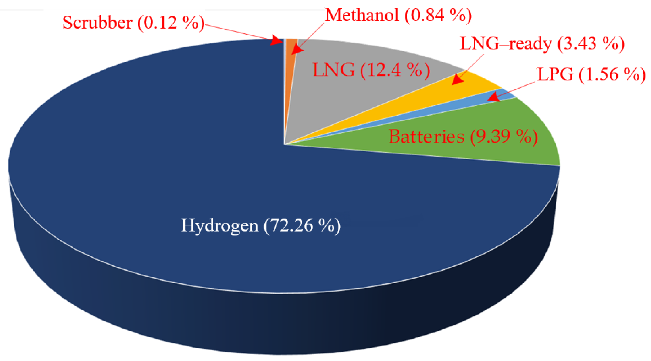
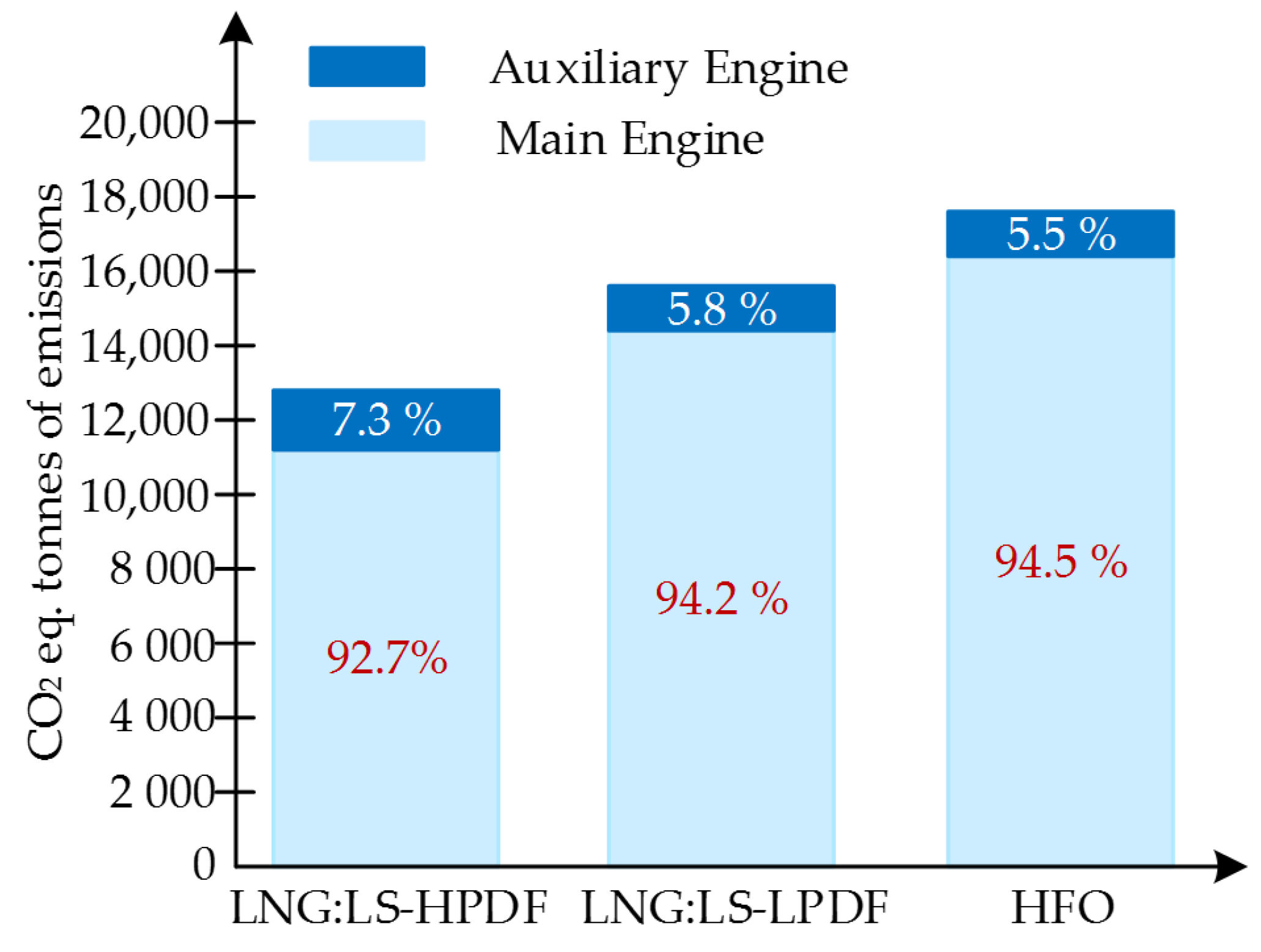
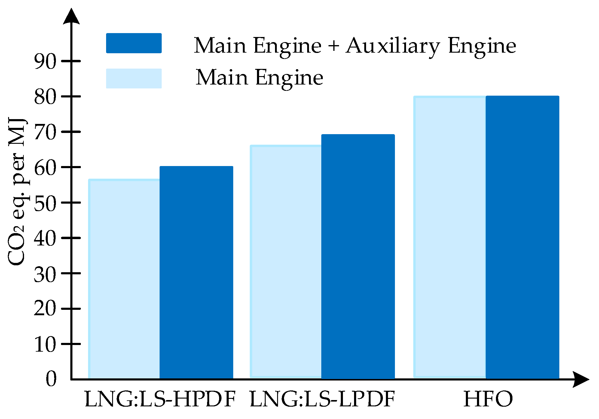
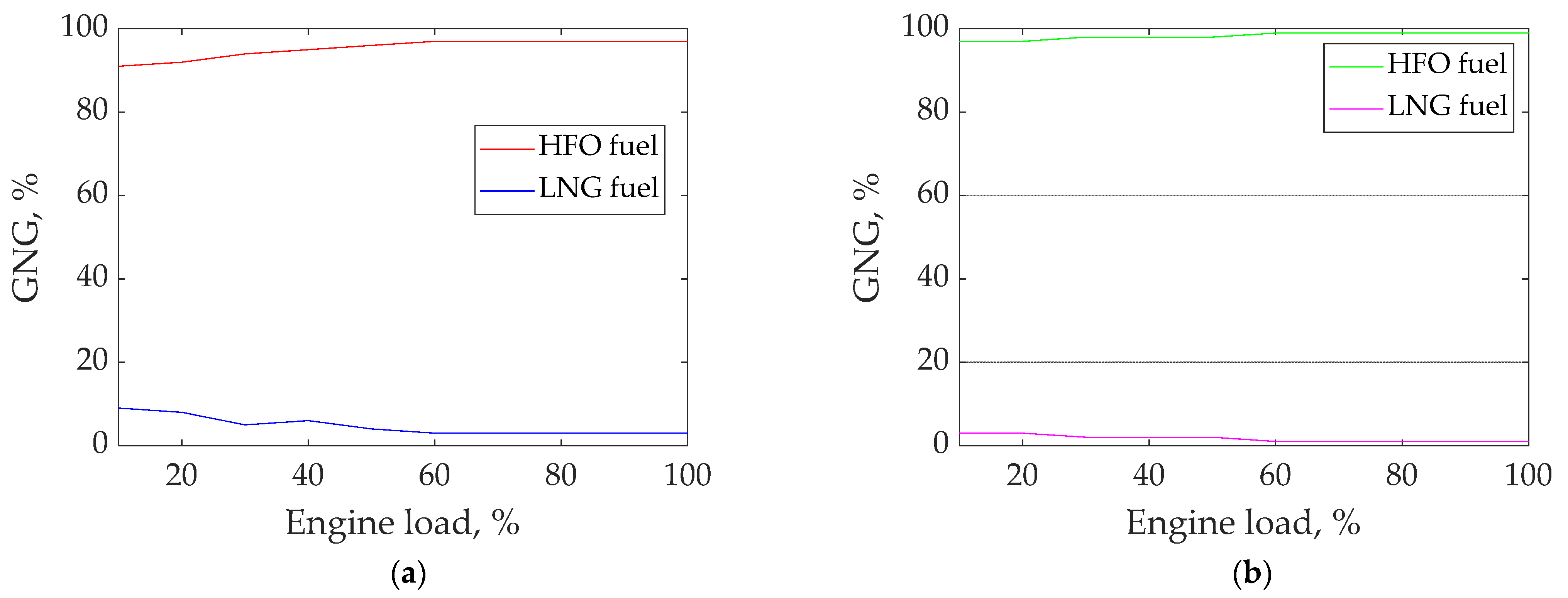
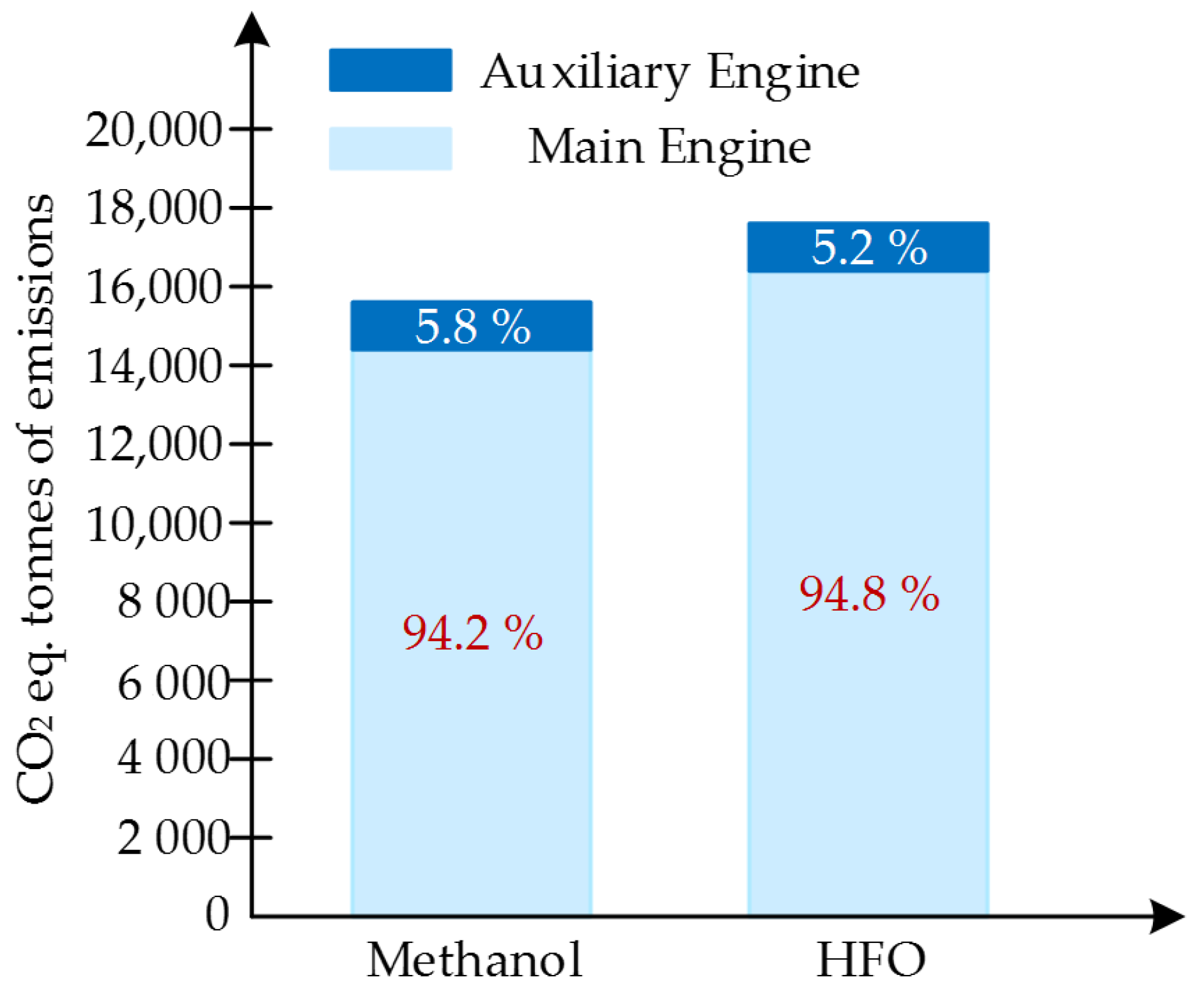
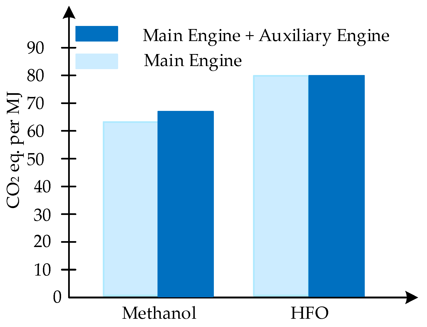
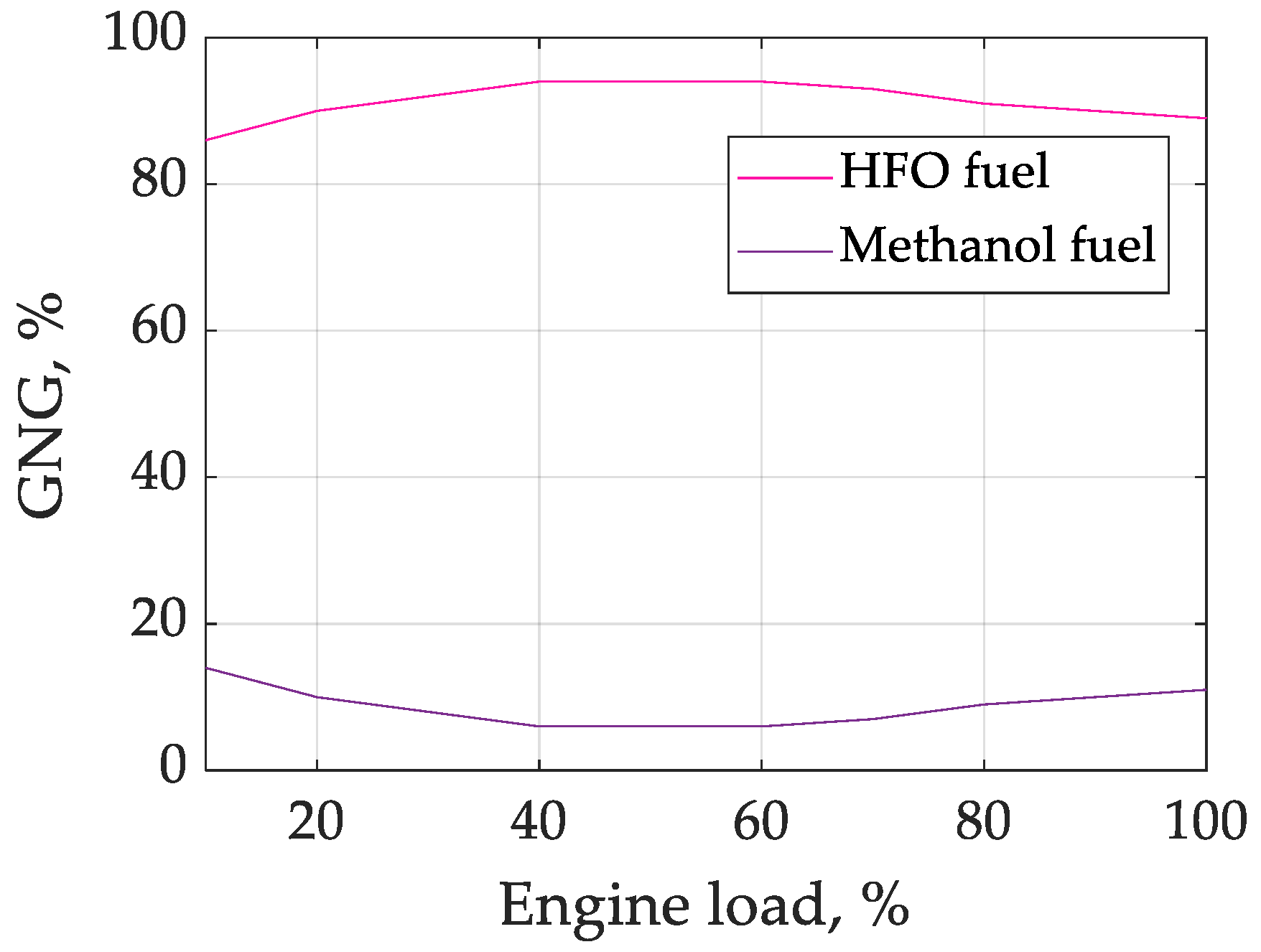
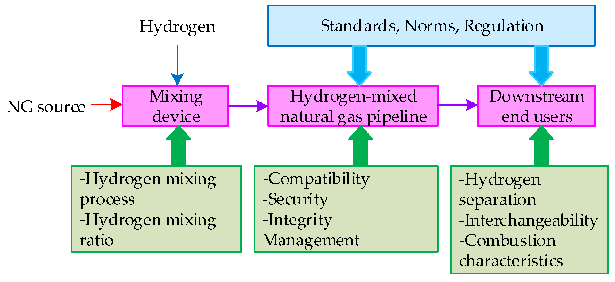
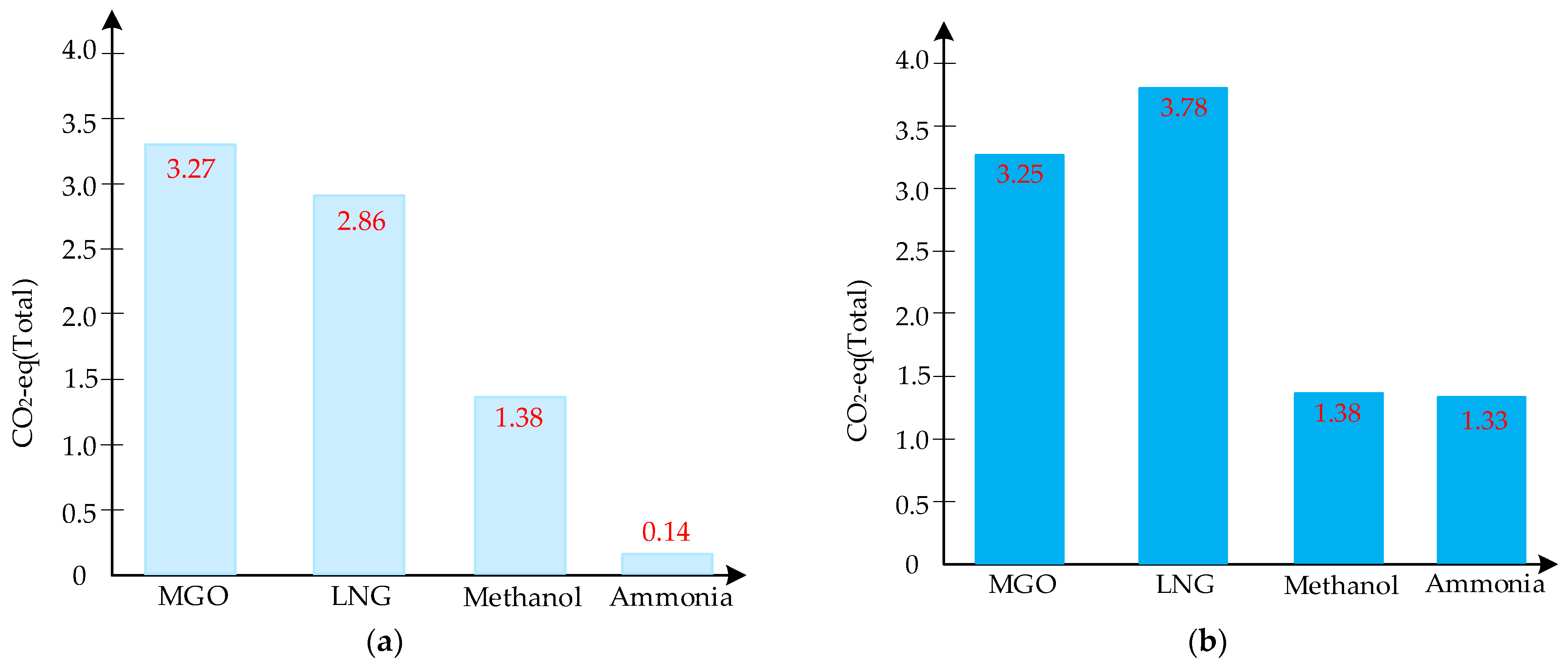


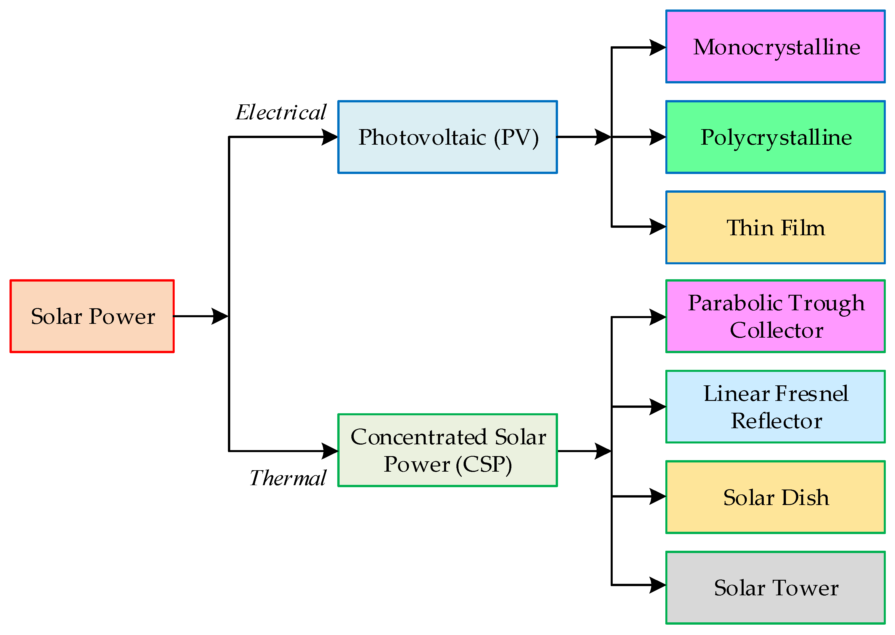
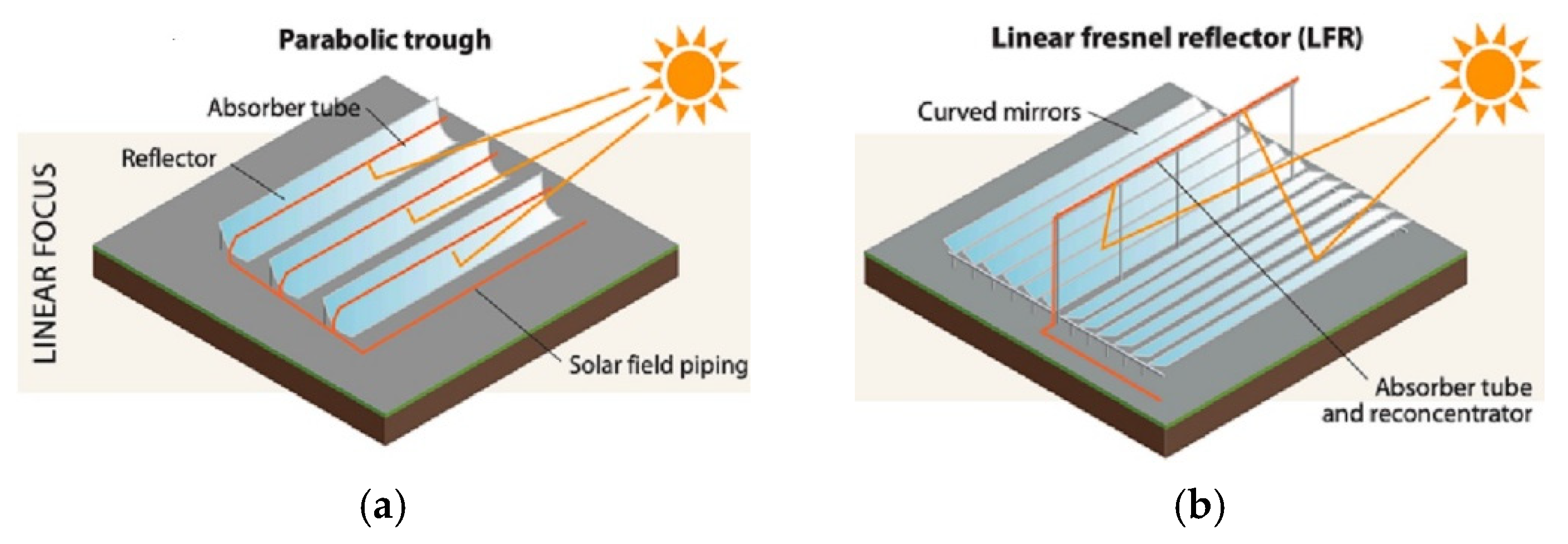
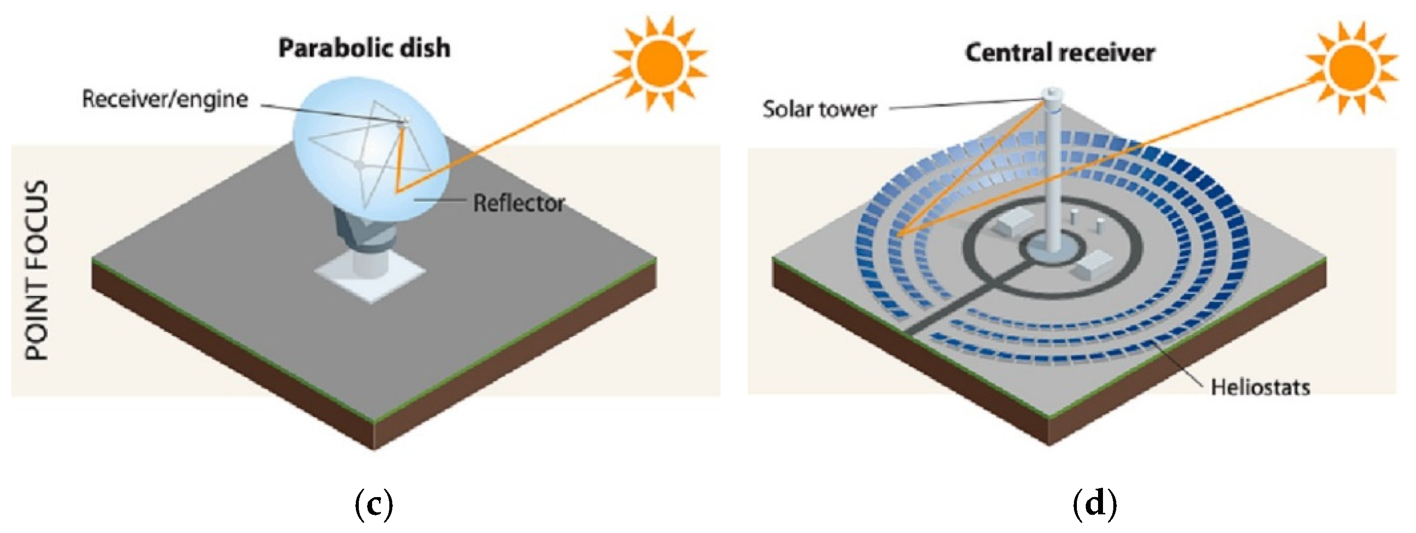
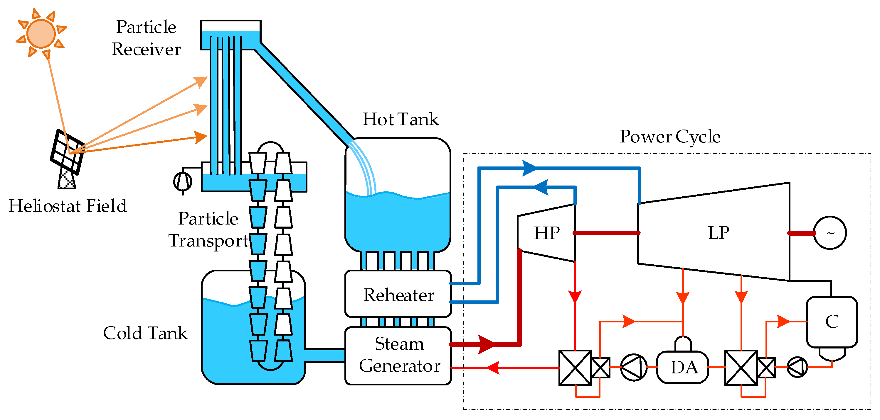
Disclaimer/Publisher’s Note: The statements, opinions and data contained in all publications are solely those of the individual author(s) and contributor(s) and not of MDPI and/or the editor(s). MDPI and/or the editor(s) disclaim responsibility for any injury to people or property resulting from any ideas, methods, instructions or products referred to in the content. |
© 2025 by the authors. Licensee MDPI, Basel, Switzerland. This article is an open access article distributed under the terms and conditions of the Creative Commons Attribution (CC BY) license (https://creativecommons.org/licenses/by/4.0/).