Abstract
The revised Energy Performance of Buildings Directive and Energy Efficiency Directive aim to accelerate the energy transition of the European building stock; however, progress remains insufficient. Off-site construction (OSC) and industrialised systems, such as Plug-and-Play (PnP) systems, are considered pivotal towards more efficient renovation practices. In this study, a PnP facade for building renovation—developed in an H2020 EU-funded research project—has been analysed with the following objectives: (i) benchmarking and assessing the construction process with a PnP facade system through the data gathered in two renovation scenarios, and (ii) identifying advantages and limitations related to implementing the technology. Two buildings—an early adopter in Budapest and a demonstration case in Pamplona—have been selected as renovation scenarios to validate the implementation of the system, testing different levels of technological integration and prefabrication. Key findings reveal that the PnP system offers significant advantages, including streamlined installation processes and reduced on-site waste compared to a conventional ventilated façade. However, the need for high workers’ tolerance, sensitivity, and precision during installation, as well as coordination protocols, has been highlighted to ensure a smooth implementation. This research contributes to the body of research on OSC technologies for building renovation, offering practical insights towards developing more sustainable construction practices.
1. Introduction
Climate change is recognised as one of the most pressing challenges of our century, with profound global implications for the environment [1], human health [2], and economic stability [3]. In response, the European Commission (EC) has launched the European Green Deal, a policy framework designed to transform the European Union (EU) into a clean, resource-efficient, and climate-neutral economy by 2050 [4,5]. The recent updates to the Energy Performance of Buildings Directive EU/2024/1275 (EPBD) [6] and the Energy Efficiency Directive (EED), EU/2023/1791 [7], reflect the commitment to support this ambitious strategy by accelerating the energy transition and aligning it with long-term sustainability goals.
Within this framework, the construction sector is crucial as buildings consume 30% of the final energy through operational use [8]. Furthermore, they are the EU’s second-largest source of greenhouse gas (GHG) emissions [9]. Since the introduction of the EPBD 2010/31/EU, energy renovation rates for residential buildings in the EU have remained at just 1%, with non-residential buildings slightly higher at 1.2% per year [10,11]. According to the EC, 85% of EU buildings were constructed before 2000, and 75% present poor energy performance [12]. The EC launched the Renovation Wave Strategy in 2020, recognising the need for more remarkable progress. This initiative aims to double renovation rates within the next decade while ensuring these efforts improve energy and resource efficiency [13,14]. Despite a moderate increase in the renovation rate, the building sector’s progress lags behind established targets, far below the 3% target set by this initiative [15].
With this in mind, the upcoming years are critical for advancing the transition towards a carbon-neutral future, where the construction industry has to intervene quickly on the existing building stock and adopt sustainable and innovative practices to meet these objectives, which is essential. Alongside these objectives, the importance of ‘deep renovation’ (DR) as a pivotal strategy for enhancing energy efficiency and sustainability in the building sector has been highlighted by previous research [16]. Lacking a consistent global definition [17], the DR concept has been addressed in the updated EPBD EU/2024/1275 [6] through the introduction of the “energy efficient first” principle. According to the directive, DR involves renovating key building components to achieve nearly zero-energy status by 1 January 2030 and zero-emission performance from that date onwards. Besides the need for a legally binding EU-wide definition of DR, a transformative shift in DR interventions is necessary to make it the default standard in policy frameworks and practical implementations [15].
Over the last decade, there has been a growing research interest in techniques that, on the one hand, accelerate renovation rates, such as off-site construction (OSC) [18], and on the other hand, technologies suitable for DR interventions, such as industrialised technologies [19,20]. This approach involves off-site manufactured envelope modules designed for direct on-site installation onto existing buildings.
Previous studies have identified barriers, including lingering negative perceptions of post-war prefabrication efforts and concerns about high upfront costs [21,22], mainly due to the involvement of various stakeholders with different objectives [23] and limited end-user awareness and more oriented to conventional construction systems [24]. More recent research, particularly in the UK, suggests a rooted cultural resistance within the construction industry intensifies these challenges [25]. According to Hosseini et al., the body of research on OSC does not provide an overall view of the construction process, highlighting the importance of cultivating support from other stakeholders, such as the industry [21].
Despite the obstacles, the research recognising the potential of industrialised construction technologies for DR of the building envelope is evident, as demonstrated by the increasing number of EU-funded projects [22]. Of particular note are the multifunctional solutions for building envelopes, which integrate passive and active features to minimise on-site operations [22,26,27]. Although numerous innovative solutions have emerged, many integrated industrialised systems are often limited to the prototyping phase [28,29] and hardly go to the market [19].
Considering the diversity of the EU building stock [30,31], the complexity of the mass renovation is evident since most member states have not yet extensively implemented off-site or mass-renovation systems to upgrade their built environments [32]. In addition to the potential of multifunctional solutions, combining their development and implementation with digital-based technologies can significantly enhance their adaptability, making them applicable to a much wider range of buildings [33]. Characterised by ambitious features, these technologies must be flexible and ready to facilitate energy upgrades, resulting in high complexity oriented to meet multiple requirements such as adapting to different climates and various geometries, supporting various uses of buildings, and addressing the needs and comfort of a wide range of occupants [19].
Despite their complexity, some research has validated their performances in improving energy efficiency [34], reducing operational energy consumption without affecting the thermal comfort conditions during construction [35]. Studies such as those by D’Oca and colleagues [22] emphasise the need to focus not only on cost-optimal technologies but also on optimising processes that minimise occupant disruption during installation and reduce overall construction time.
In this context, Plug-and-Play (PnP) solutions have considerable potential for enhancement and growth [36]. The term “plug and play” was initially used in the computer industry and has recently been adopted in the construction sector [37] to refer to standardised, off-site components that facilitate straightforward on-site assembly. These solutions offer several benefits, such as reducing the renovation time, minimising disruptions to occupants, lowering the overall costs, enhancing energy and material efficiency, and promoting urban mining and material reuse [22,27,36].
Effective implementation of PnP technologies requires a well-coordinated construction process methodology, highlighting the importance of stakeholder collaboration [38]. Inefficiencies in design, logistics, production, and installation processes can inflate costs, underscoring the need for meticulous planning and execution [39]. Several EU-funded projects, including MORECONNECT [27], BERTIM [40], 4RinEu [41], RenoZeb [42,43,44], INFINITE [45], and PLURAL [46,47,48], have already tested PnP systems in real-world scenarios. Despite the potential time savings these projects offer due to their innovative technologies, only the RenoZeb project provides quantitative data on its construction phase. However, it does not provide detailed insights into the construction times associated with each phase and working labour [43].
Although industrialised construction solutions have been adopted for new buildings for years, the main challenge of PnP technologies lies in their interoperability with existing envelopes, as renovation involves the convergence of two different systems. Implementing these technologies in real environments is crucial for identifying room for improvement towards their development. Therefore, this study highlights and explores a multifunctional PnP envelope—developed in an EU-funded research project—deepening its potential in accelerating building renovation, considering its adaptability to diverse real-world renovation scenarios [33]. The objectives are (i) benchmarking and assessing the construction process experience with a lightweight steel-based multifunctional PnP facade system, offering insights through the data collected in two renovation scenarios, and (ii) identifying the advantages and limitations of its implementation. The first renovation scenario is a municipal kindergarten in Budapest, chosen due to the building type’s high energy consumption [49]. The second scenario, located in Pamplona, allowed testing other PnP modules’ configurations with different technological integration and prefabrication levels and the installation in a two-storey building.
The manuscript is structured as follows: Section 2 outlines the technical specifications of the PnP façade system and its specific configurations in the two renovation scenarios, defines how the construction process has been assessed, and introduces the method used to benchmark the PnP solution with a conventional system in terms of labour performance and waste generation. Section 3 presents the main findings, emphasising the practical implementation of PnP technology across each phase of the construction process in the two renovation scenarios, providing a quantitative comparative synthesis of the two execution times collected on-site. Section 4 critically examines the main findings, highlighting the advantages and limitations of the PnP façade system and identifying potential improvement areas. Moreover, to relate the quantitative data collected regarding installation time, labour performance, and waste reduction to the existing context, Section 4 also reports benchmarking the PnP solution against a conventional ventilated façade system for building renovation. Section 5 outlines the conclusion.
2. Materials and Methods
This section is structured according to the objectives of this study, describing the overall qualitative and quantitative approach used to assess and benchmark the construction process with a PnP façade for building renovation. The first part of Section 2 clarifies the features of the PnP façade module to outline its technical design and configurations, thus easing the reader’s interpretation of the results. The second part reports the motivations behind selecting the two renovation scenarios, thus describing the pre-existing conditions of two buildings, an early adopter in Budapest, and a demonstration case in Spain.
The third part specifies how the construction process has been assessed through a qualitative approach, while the fourth part outlines the method used for benchmarking the PnP solution compared with a conventional ventilated facade system, highlighting its labour performance, and waste generation. Figure 1 offers an overview of the section, reporting the respective outcomes described in Section 3 and Section 4.
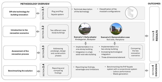
Figure 1.
Graphical representation of the methodology adopted.
2.1. Off-Site Construction in Building Renovation: The Plug-and-Play Façade System
The PnP module is a preassembled lightweight, cold-formed steel-based façade designed for building renovations. It can vary in size to suit specific project needs, with heights up to 4 m and widths ranging from 1.3 to 2.4 m. Aside from being industrialised and assembled off-site, the key differentiating component compared to a conventional façade system for deep renovation is its installation method. It is based on an anchoring system similar to those used in curtain walls and is designed to minimise installation time. The system is designed to be installed over the existing envelope of the building under renovation, anchored to the structural elements, whether the existing envelope itself or the edge of the slab. Starting by defining the layers from the outside to the inside, the PnP module consists of four main layers, as represented in Figure 2.
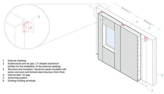
Figure 2.
Plug-and-Play façade module description.
The outer layer (1) is the exterior finish, determining the module’s final aesthetic. It is fixed on an aluminium substructure that constitutes a ventilated façade (2) with an air cavity that can accommodate pipes and other services. The substructure is connected through steel brackets to the third layer (3), composed of metal-faced sandwich panels fixed on a cold-formed steel structure, providing thermal insulation, acoustic performance, fire resistance, and water tightness for the module. An interlocking element placed in the cold-formed steel structure allows the module’s installation on the existing façade through an anchoring system. The space between the PnP module and the existing façade (4) is formed due to the thickness of the anchoring system, which creates a still air gap layer. This layer serves a dual purpose: it accommodates the anchoring system and allows adjustments to smooth any irregularities or out-of-plane in the façade; moreover, it can be filled with extra insulation or left as a still air gap.
The PnP façade system is designed to streamline the installation process, with a focus on the adaptability of its anchoring system. Once installed, this mechanism securely attaches the PnP panels while allowing small movements out-of-plane and horizontally, enabling precise positioning. Additionally, it is engineered to support two panels simultaneously to minimise the number of anchors installed.
Each PnP module requires at least two support points at its top section for proper fixation, with adjacent modules sharing the same anchoring points. In the lower part, the modules are interconnected with the panels installed on the lower floor through a pin. For panels on the ground floor, additional support is provided by two anchors at the bottom.
Plug-and-Play Façade Module’s Configurations
In order to fast-track market-ready integrated solutions, the proposed PnP module has been designed to allow the installation of different third-party products (TPPs) such as ventilated façade profiles, different types of claddings, windows, sun shading systems, photovoltaic panels, and potentially others. The interoperability and inter-compatibility of different products with the presented solution in the design phase have been explored in previous research [50]. Depending on the project requirements, the PnP module can be implemented with active or passive TPPs integrations towards multifunctional solutions, allowing different configurations. In this study, different module configurations have been tested in the two renovation scenarios to highlight advantages, limitations and potential room for improvement.
Each configuration differs from the other for two key factors: (i) the level of technological integration, referring to the incorporation of TPPs into the module, such as windows and active systems, and (ii) the level of preassembly, defined by the extent to which the module’s components are preassembled off-site in a controlled manufacturing environment. Table 1 describes each module’s configuration, highlighting their features, differences, and applicability.

Table 1.
Description of PnP module configurations.
2.2. Introduction to the Renovation Scenarios
The selection of real-world scenarios was essential to evaluate the technical feasibility and assess the renovation process with PnP modules. Diverse pre-existing conditions characterise the renovation scenarios; different module configurations were also tested for each. This approach has been pursued to highlight the various emerging technical challenges, aiming to understand the system’s advantages and limitations comprehensively. The following paragraphs describe the pre-existing conditions of the two renovation scenarios—a kindergarten in Budapest, Hungary, and two test cells in Pamplona, Spain.
2.2.1. Scenario 1: Kindergarten Zöld Liget in Budapest, Hungary
The first renovation scenario is a one-storey building constructed in 1952 in a suburban area of Budapest. It is characterised by a rectangular floor plan (58 m × 9.5 m) comprising four primary classrooms and all necessary support spaces for kindergarten activities. The structure consists of reinforced concrete with brick infill walls, and the building is 4 m tall. The building’s more extensive facades are oriented toward the southwest and northeast. Before the renovation intervention, the façades lacked insulation, although the double-glazed windows with PVC frames and external shading have been recently replaced. The renovation process, reported in the “Results” section, involves the façades’ over-cladding while keeping the existing windows. Despite its regular shape, the façades present a high solid–void ratio, making it an ideal candidate for assessing the construction process of the PnP module in this scenario. The pre-existing conditions of the building are shown in Figure 3.
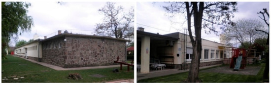
Figure 3.
Pre-existing conditions of the Kindergarten Zöld Liget in Budapest, Hungary.
2.2.2. Scenario 2: Test Cells in Pamplona, Spain
The second renovation scenario involves two identical two-storey buildings installed at the University of Navarra’s R&D facilities in Pamplona. These fully monitored buildings serve the research project as test cells, with facades exposed to solar and wind levels due to their unshaded location. Each building has a rectangular footprint of 4.25 × 2.67 m and a height of 5.5 m. A tubular metal structure characterises the two buildings, while the insulation of the walls and roof is made of metal-faced sandwich panels.
The external layer consists of a ventilated façade isolated with mineral wool and clad with metal sheets. The buildings required proper preparation to install the PnP modules: Figure 4 shows the original conditions of the façades on the left, while on the right, the façades stripped of their metal cladding are prepared to receive the renovation intervention.
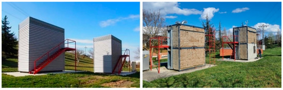
Figure 4.
Pre-existing conditions of the test cells in Pamplona before and after removing the external finishing.
2.3. Assessment of the Renovation Process
The methodology used for this study allowed for a comprehensive understanding of the PnP façade implementation in renovation interventions, considering technical challenges associated with both one-storey and multi-story installations and different PnP modules’ configurations. Figure 5 displays an overview of the renovation process, breaking each phase into its main sub-phases.
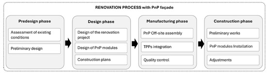
Figure 5.
The renovation process’s phases with the PnP system.
The assessment of the construction processes of the two renovation scenarios has been conducted through a qualitative approach, encompassing the (i) pre-design, (ii) design, and (iii) construction phases. The manufacturing phase was excluded from the study as it relates to the product level rather than the project level. Furthermore, the pre-design and design phases were highlighted as critical in influencing the construction phase, particularly in renovation projects.
The assessment process involved stakeholders, such as designers, manufacturers, contractors, and building owners, who participated in a series of group discussions during the EU-funded project’s meeting. These discussions were key in collecting the insights and perspectives reported in the “Results” section, including various perspectives throughout the different phases.
The pre-design phase mainly consists of assessing the pre-existing conditions of the building through a detailed survey and identifying whether the PnP system is suitable as a renovation solution. Geometrical information is collected using laser scanners or in situ measurements to verify building dimensions. The mechanical characterisation of the façade is conducted through testing, including pull-out tests to determine the structural integrity of the existing walls. Structural verification followed Eurocodes and the national regulations applicable to each pilot project.
The design phase includes planning the PnP modules’ layout on the existing façade and addressing technical details beyond the module installation. This intermediary phase enabled the qualitative assessment of stakeholder interactions and the identification of design patterns that influence the feasibility of industrialised systems for energy-efficient renovations. Data collection during this phase included stakeholder feedback, qualitative observations, and thermal performance calculations following ISO 13786:2018 [51] standards.
Three key steps have been identified regarding the construction phase: preliminary works, PnP module installation, and adjustments. The preliminary stage characterises the preparation of the site, the removal of the existing facilities that could obstruct the PnP module installation, and material unloading. The PnP module placement step involves installing the anchoring systems and ensuring their alignment to facilitate smooth module installation.
After installing the modules, some adjustments are needed to ensure airtightness, adjust the planarity of the external finishing, install missing or previously removed elements, and complete the entire envelope. Additionally, the installation process was monitored across various phases to quantify the panel installation time and identify potential improvements. The analysis of the construction process, based on qualitative and quantitative analysis, provides valuable insights into the scalability and implementation of the PnP façade system for building renovations, addressing practical challenges.
2.4. Benchmarking the PnP Façade Solution
This section reports the quantitative method used to benchmark the PnP module solution with a conventional system for building renovation; this approach compares an off-site and an on-site solution under similar conditions in terms of labour performance. A conventional ventilated façade system has been selected as it closely aligns with the PnP façade features, thermal performance and aesthetic characteristics. While other systems, such as the ETICS (external thermal insulation composite system), are commonly used in façade renovation, ventilated façades provide a comparable target to benchmark the solution due to the similar structural and technical properties as a multi-layer dry construction system. The ventilated façade comprises three primary layers: insulation, the ventilated façade structure and anchoring, and the external cladding.
The comparative analysis was conducted using a combination of primary data from Scenario 2’s construction phase assessment and secondary data obtained from the BEDEC database. This database, developed by the Catalonia Institute of Construction Technology (ITeC), provides comprehensive and reliable information tailored to the Spanish construction sector, including life-cycle data, economic metrics, environmental impact assessments, and waste management insights.
The analysis focused exclusively on identifying the renovation times for the façade of Scenario 2, emphasising the installation phase of the PnP modules. The labour performance data for a conventional system were taken from the database and correlated to Scenario 2 for comparison. This approach enabled the comparison of off-site and on-site installation processes under comparable conditions. The BEDEC database was a key reference for characterising the ventilated façade solution and benchmarking the PnP system’s performance against conventional methods.
- Labour performance analysis: In order to benchmark labour performance, ratios from the database were used, focusing on work efficiency metrics for specific tasks. Data were extracted in terms of hours per square meter (h/m2), representing person-hours required per square meter. This metric allowed for a standardised comparison of work efficiency between the off-site and the on-site construction systems.
- Waste generation analysis: The analysis of waste generation followed the European List of Waste (LoW) classification system, which provides a standardised framework for waste management and categorisation [52]. The waste generated during the PnP system’s installation phase was compared against the waste metrics derived from the conventional façade system, as reported in the secondary data offered by the BEDEC database.
As the PnP façade system is a solution under development and not already available on the market, economic comparisons were excluded from the study’s scope. Instead, the research prioritised the evaluation of labour performance and waste generation, as these indicators are a priority in assessing the sustainability and efficiency of such systems.
3. Results
This section presents evidence of the technical feasibility of the PnP façade application across the two renovation scenarios by analysing the pre-design, design, and construction phases. The technology switch from laboratory implementation to real-scale application required an intermediate step to validate the system and mitigate potential risks in the real-environment application. Before the application in the two renovation scenarios, a preliminary real-scale test was performed to validate the construction phase of the modules [50], providing key insights and establishing general guidelines for installing the modules. As highlighted in the Section 2, the two renovation scenarios differ in features and module configurations implemented to assess the renovation process comprehensively. Notably, in the second scenario, which was developed chronologically after the first, the level of technological integration of TPPs and the degree of preassembly have been increased. This approach allowed us to test the increasingly complex and multifunctional PnP modules.
3.1. Scenario 1: Early Adopter Building’s Renovation Process
The first renovation scenario focused on improving thermal comfort conditions by addressing the absence of façade insulation. The PnP module was designed to fulfil the architectural design needs and the performance requirements tailored to the climate zone of the building. Budapest is in a Cfa climate zone, classified as ‘humid subtropical’ according to the Köppen–Geiger classification [53]. In this zone, the coldest month in winter conditions is January, with an average temperature of −0.5 °C, while the warmest month is July, with an average daily temperature of 22.1 °C. The renovation process’s phases are described in detail in the following paragraphs.
3.1.1. Scenario 1: Pre-Design Phase
A laser scanner survey was conducted to determine the building’s dimensions accurately. A pull-out test complemented this geometric survey to assess the mechanical resistance of the existing façade, ensuring that the structural elements could adequately support the weight of the PnP modules once installed. This phase of the construction process is important in defining the strategy for façade renovation. Given the two main façades’ complexity and length of 58 m, the primary goal was to over-clad the most extensive area possible with complete PnP modules; however, some building areas have been renovated using ventilated façade technology for specific requirements. Moreover, in this phase, a comprehensive evaluation of the thermal performance of the building envelope has been conducted; mainly, the thermal transmittance of the façades to be renovated has been measured (starting U-value of the façade, U = 1.77 W/m2K [54]).
3.1.2. Scenario 1: Design Phase
The design phase involved both the architectural and technical design of the PnP modules. Starting from the architectural design of the modules, the operations started by transferring into 2D drawings the geometrical information obtained from the laser scanner survey of the building. Using Computer-Aided Design software (Autocad v2003) and based on the shared 2D drawings of the pre-intervention status of the building, the manufacturer detailed the PnP modules, working with millimetre-level precision. For this specific scenario, two modules’ configurations have been chosen to align with the renovation strategy: (i) an opaque module with an external layer partially installed; (ii) a holed module without an integrated window, as shown in Figure 6.
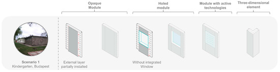
Figure 6.
Module configurations implemented in Scenario 1.
The modules’ configuration choices were driven by two primary considerations: first, to retain the existing windows, and second, to allow the passage of drainage systems through the ventilated façade air gap, which had to be installed on-site. The modules’ dimensions were designed after carefully analysing the solid-to-void ratio of the façade. Considering the technical and structural constraints, each module is installed in correspondence to a single window.
The renovation covered 530 m2 of the façade, with 48 PnP modules covering 320 m2. To optimise the manufacturing, the modules were standardised into four main dimensions, ranging from 1.3 to 2.5 m in width and 3 m in height, considering transportation and installation limitations. Table 2 summarises the main PnP modules’ features related to Scenario 1.
Table 2.
PnP modules’ features in the two case study buildings.
Shifting to the modules’ performance design, the primary objective was to guarantee an adequate thermal improvement of the façade. The key layer contributing to the thermal performance is the sandwich panel insulated with stone wool (thermal conductivity = 0.042 W/mK; density = 100 kg/m3; specific heat capacity = 900 J/kgK). Taking into account the 5 cm still air gap (thermal resistance = 0.11 m2K/W) in between the existing façade and the back face of the PnP module, the installation of the PnP module increased the thermal shift of the existing envelope of 3.11 h (considering a thermal variation period of 24 h) and the thermal resistance of 4.348 m2K/W, thus decreasing the thermal transmittance of the building envelope from 1.77 W/m2K to 0.16 W/m2K.
3.1.3. Scenario 1: Construction Phase
In this subsection, the focus is on presenting the results of the practical implementation of the PnP technology, encompassing each sub-phase of the construction phase: (i) preliminary works, (ii) PnP modules installation, and (iii) final adjustments. The analysis technically examines the issues encountered during the construction phase, the factors that influenced the ease and speed of installation, and the solutions applied to address them.
Preliminary works: The preliminary works focused on on-site preparation, dismantling, and removing any existing façade elements that could obstruct the installation of the PnP system, as well as receiving and storing materials. A designated storage area was established to avoid interfering with the kindergarten’s daily use. In this case, the building’s perimeter garden served as a dedicated storage space.
The preliminary works for Kindergarten Zöld Liget included removing concrete shading elements and provisionally removing waterspouts and external lighting. These last elements were reinstalled during the adjustment phase. Material handling and storage were critical to ensure efficient and orderly site operations. Proper organisation of stored materials was essential to facilitate smooth subsequent on-site movements. The panels were unloaded using a mechanical forklift from delivery trucks and moved to the construction site’s storage space.
PnP module’s installation: The module’s installation phase consisted of two main tasks: installing the anchoring systems and placing the PnP module. The anchoring elements were installed using laser tracing to ensure precise alignment for a smooth installation of the PnP modules. In this scenario, the connection between the anchoring system and the existing building is solved by a chemical anchor that guarantees the interconnection between the screws of the anchoring system and the existing wall. Figure 7 shows the anchoring system installed on the building’s load-bearing concrete structure: the upper anchoring system serves as a hanging point for the PnP module.
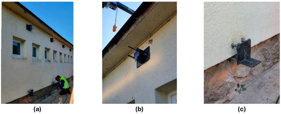
Figure 7.
Preliminary works: (a) installation of the anchoring system; (b) detail of the upper anchoring system; and (c) detail of the lower anchoring system.
At the same time, the lower one provides additional support and ensures the module’s verticality. The drying phase of the chemical anchor takes approximately 24–48 h, depending on the drying process, which can vary based on external weather conditions. The anchoring system arrived on-site unassembled, increasing the required labour hours for this task. Once the anchors were set and aligned, the installation of the PnP modules started.
After being manufactured in a factory in northern Italy, the PnP modules were shipped to the construction site by truck. They were transported on a wooden structure designed to hold two modules simultaneously, as shown in Figure 8a. The wooden frame was chosen for its potential for reuse. The modules were positioned vertically to optimise the truck’s nesting and facilitate easy lifting of the modules before installation.
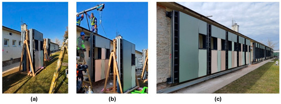
Figure 8.
Installation phase of the PnP modules: (a) modules’ shipment on wood structure; (b) modules’ uplifting by crane; and (c) installation of the northeast façade’s modules.
Hence, the module’s structure incorporates two eyebolts installed in the top part, allowing the panels to be lifted by a small mobile crane, which, in this case, has been placed on the building’s roof, as shown in Figure 8b. In this renovation scenario, the rooftop crane was utilised mainly to lift the panel. At the same time, auxiliary equipment and additional workers ensured the precise position of the module on the façade. Seven workers were necessary to install the panels since installing a crane that did not allow movement in different directions caused inefficiencies in this phase. This process was repeated for each PnP module, as shown in Figure 8c, with slight horizontal and out-of-plane adjustments due to the anchoring system.
However, during installation, it was noted that the initial laser scanner survey lacked millimetric precision, leading to minor misalignments between the PnP modules’ holes and the existing windows. Thus, on-site modifications were needed, such as manually cutting the HPL panels, consequently increasing construction time; this could have been avoided by double-checking laser scanning survey dimensions or allowing greater tolerances for window openings. The opaque PnP modules with partial external finishing allowed on-site interventions, such as installing downpipes and electrical wiring and minimising the number of cladding elements used for the exterior cladding. Therefore, in this phase, the installation of the remaining HPL panels was completed, and the vertical and horizontal joints of the ventilated façade were fine-tuned, as allowed by the type of substructure.
In this scenario, the PnP modules, while compatible with windows, did not include them, necessitating an additional step to install an insulated frame around the windows to address thermal bridging issues. This final step helped correct window misalignments with the module’s holes detected previously, resulting in manual on-site work.
Adjustments phase: The construction phase concludes with some adjustments. As previously mentioned, modifications were necessary to ensure compatibility between the existing building and the PnP modules. This phase focuses primarily on completing construction tasks that cannot be addressed with the PnP system. Specifically, additional on-site work addressed the technical connection between the new envelope and the roof. Additionally, this phase was utilised to reinstall components such as exterior lighting. Finally, the building’s surroundings were cleaned and restored to its original state after construction. Figure 9 shows the complete, renovated façade.
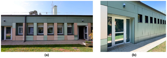
Figure 9.
Scenario 1 complete building renovation: (a) southeast façade; and (b) northeast façade.
3.2. Scenario 2: Demonstration Case Building’s Renovation Process
The second renovation scenario has three main objectives: (i) validate the system in a two-storey building; (ii) validate the installation of PnP modules incorporating different TPPs such as windows and photovoltaic panels; (iii) validate a higher degree of prefabrication by testing three-dimensional corner modules. The modules have been designed according to the climate zone of the buildings. Pamplona is located in a Cfb climate zone, classified as ‘humid temperate’ according to the Köppen–Geiger classification [53]. In this zone, the coldest month in winter conditions is January, with an average minimum temperature of 3.9 °C, while the warmest month is August, with an average daily temperature of 19.4 °C. In the following paragraphs, the renovation process’s phases specified in Section 2 are described in detail.
3.2.1. Scenario 2: Pre-Design Phase
In this phase, the original building documentation was gathered. Since the structure is prefabricated and the execution drawings were available, the geometrical survey using laser scanning was considered unnecessary. The dimensions from the original plans were manually verified and found to be accurate. Regarding the structural’s mechanical characterisation, the steel building structure could allow the installation of the modules.
3.2.2. Scenario 2: Design Phase
In the second scenario, the design phase was carried out with the contribution of an internal member of the University of Architecture of Navarra, highlighting the priority towards the aesthetic result of the façade, with a minimum number of joints. Collaborating with the final client, the manufacturer designed the PnP modules’ to be installed, taking care of the technical details of TPPs integrations in each module’s configuration. In this scenario, four modules’ configurations have been installed (Figure 10) to align with the renovation strategy: (i) an opaque module with an external layer completely installed; (ii) a holed module with an integrated window; (iii) a module with an integrated photovoltaic panel; and (iv) a three-dimensional module for the building’s corners.
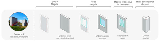
Figure 10.
Module configurations implemented in Scenario 2.
The choices were driven by the main objective of covering the entire building envelope using the PnP façade system, validating different modules’ configurations. Considering the technical issues related to the technologically integrated modules, some precautions have been taken during the design phase; for instance, windows were selected with hidden handles to avoid damage during transportation and installation.
In this scenario, the dimensions of the modules have been designed mainly considering transportation limitations since the structural conditions did not pose any limitations in the anchoring system positioning, given the small dimensions of the building. The renovation covered a total façade area of 57 m2 out of 66 m2 per building, thus renovating 114 m2 of the façade with PnP module. Thirty-six modules have been installed, including eight three-dimensional modules for the corners of each building. The modules on the first floor were designed with width dimensions up to 2.1 m and up to 2.6 m in height. Table 3 summarises the main PnP modules’ features related to Scenario 2.
Table 3.
PnP modules’ features in Scenario 2.
Focusing on the performance design of the modules, the key layer contributing to the thermal performance of the PnP module is the sandwich panel, also in this case insulated with stone wool (thermal conductivity = 0.042 W/mK; density = 100 kg/m3; specific heat capacity = 900 J/kgK). Considering the significant out-of-plane of the two test cells, approximately a 7 cm still air gap (thermal resistance = 0.13 m2K/W) can be considered between the existing façade and the back face of the PnP module. The PnP module’s installation increased the existing envelope’s thermal shift by 2.50 h (considering a thermal variation period of 24 h) and the thermal resistance of 3.871 m2K/W.
3.2.3. Scenario 2: Construction Phase
Consistent with Scenario 1, the analysis technically examines the issues encountered during the construction phase, the factors that influenced the ease and speed of installation, and the solutions to address them.
Preliminary works: The preliminary works concentrated on preparing the site, removing and dismantling the protruding features that could obstruct the installation of the modules, and managing the receipt and storage of materials. No additional effort was required regarding site preparation since the test cells were isolated and did not host any human activity. First, the existing façade cladding in metal sheets was removed to expose the structural elements, and the existing stairs to access the first floor of the test cells were provisionally removed to be reinstalled after the renovation intervention. The primary challenge was ensuring proper access for the crane truck to facilitate the installation of the modules.
PnP module’s installation: The PnP module’s installation phase starts with anchoring systems, following the layout plans. Tools such as self-level lasers and folding mobile scaffolds were employed to facilitate installation on the second floor, and the anchors were placed as designed. However, due to the installers’ unfamiliarity with the system, the anchoring systems were welded to the steel structure, resulting in restricted movement of the anchors along the façade plane.
During the installation phase, a significant issue was identified with the anchoring systems. Specifically, the elements were manufactured with an exceeding width dimension of 1 cm, which did not allow for a smooth installation of the PnP module. Therefore, it was necessary to slightly modify the anchoring system on-site before installing it. This underscores the critical importance of verifying the dimensions of all components through preliminary checks, emphasising the need for rigorous quality control within the supply chain. Additionally, the lower anchoring system consisted of a non-industrialised steel plate welded to the main structure of the pilot, adding another operation on-site. It was observed that refinements are necessary to provide a lower anchoring system of the first row of the PnP panels to achieve a streamlined process.
Due to safety reasons, the PnP modules’ structures cannot be stored on-site, so they have been delivered on-site “Just in Time”. Once unloaded from the crane truck, the panels were immediately installed in the building. A crane truck was employed to lift and position the panels, allowing for precise movement in all directions. Two workers assisted in positioning the modules on the anchoring system and employed a folding mobile scaffold for the second-floor installations.
Based on observations from Scenario 1, it was determined that the PnP modules’ installation phase could be effectively managed with two operators guiding the panels and one operator controlling the crane. Figure 11 shows the complete installation process of the PnP modules on one of the two test cells.

Figure 11.
PnP modules’ installation: (a) positioning of the first panel on the ground floor; (b) installation of a first-floor panel aligned with the ground floor panel; and (c) completed façade.
During installation, the vertical and horizontal alignments of the panels were adjusted using the anchoring system. The ground floor panels are leaning on a base element in the lower part, while the top part is fixed to two anchoring elements. The first-floor panels are anchored in their top part to two anchoring elements, while the lower end is interlocked to the ground-floor panels using male-female screws, ensuring a precise and secure fit between the panels. One of the key components in the Spanish pilot installation process was the three-dimensional element for the building corners. These panels are characterised by their rigidity, which makes them easy to install. Their dimensions are precisely matched to the anchoring system, allowing them to be a reliable reference point to start the alignment process. Figure 12a,b show the installation of a corner panel on the ground and first floors of the building. The process was repeated for the adjacent facade, where one module was placed close to the corner modules, and their horizontal and out-of-plane placements were adjusted when needed.
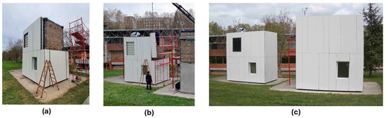
Figure 12.
PnP modules’ installation: (a) completion of the ground floor installation with corner panels; (b) positioning of a corner panel on the first floor; and (c) completed renovation.
In this scenario, the opaque PnP modules were delivered with the external finishing completely installed, thus reducing the time for the adjustments phase. Nevertheless, some fine-tuning was necessary, particularly in aligning the HPL panels of the ventilated, which was possible through the mechanical systems of the façade profiles.
Adjustments phase: This project phase also involved additional on-site tasks, such as capping the roof perimeter until the completion of the entire renovation process, as shown in Figure 12c. An essential advantage in this scenario was the windows integration in the PnP, which eased the adjustments phase compared with Scenario 1. Existing components, such as exterior staircases, have been reinstalled, and finally, the site was cleaned and restored to its original condition.
3.3. Comparison Between the Two Renovation Scenarios
This paragraph compares the two renovation scenarios to synthesise and compare differences and similarities in the construction process. The comparison aims to report in a structured way the quantitative data related to the construction phase’s execution time to identify areas for improvement, considering their profound differences, from the building type to the tools used to realise intervention.
Table 4 synthesises the technical features of each scenario. Each sub-phase (i. preliminary works, ii. PnP module’s installation, and iii. adjustments) was divided into specific tasks to achieve a structured collection of the execution time data, enabling detailed cross-scenario comparisons and correlations (Table 5).
Table 4.
PnP modules’ features in the two renovation scenarios.
Table 5.
Summary of the execution time of the two scenarios’ construction phase.
In Scenario 1, the Budapest early adopter building, 48 PnP modules were installed, covering a façade area of 320 m2 within 127 days, while in Scenario 2, the Pamplona demonstration case, 36 PnP modules were installed in 13 days, covering a surface of 114 m2. When comparing the construction time ratios relative to the specific facade areas, Scenario 1 achieved a construction rate of 2.52 m2/day, while Scenario 2 reached 8.76 m2/day. As previously highlighted, Scenario 1 served as an early adopter of the PnP system, allowing the identification of patterns and practices to enhance installation efficiency in Scenario 2.
Besides the reported construction phase’s execution time (Table 5), it is essential to emphasise that the results are influenced by site-specific boundary conditions, which complicate generalisation and a precise comparison. Nonetheless, several qualitative observations related to each sub-phase of the construction phase are necessary to highlight the differences and similarities between the two renovation scenarios.
- Preliminary Works:
- Site preparation and material reception: In Scenario 1, special care was required to maintain functionality as a kindergarten during the renovation intervention. Due to space restrictions and the limited working areas, additional efforts were required for site preparation compared to Scenario 2.
- Removal and disassembling of obstructing elements: In Scenario 1, external installations like drainage pipes had to be removed. Conversely, in Scenario 2, the pre-existing façade in metal sheets needed to be disassembled. The significant difference in execution times between the two scenarios was influenced by the dimension disparity between the two buildings, introducing varying levels of complexity to the tasks.
- PnP Modules Installation:
- The PnP modules’ installation phase required 3424 h in Scenario 1, while only 310.75 h in Scenario 2. This disparity, reflected in the construction time ratio (h/m2), highlights the profound difference between the two scenarios; on the one hand, the ratio is influenced by the mitigation strategies adopted in Scenario 2 based on the lessons learned in Scenario 1; on the other hand, other issues emerged during the process:
- Size modifications: Issues with laser scanning tolerances during the survey led to on-site panel adjustments in correspondence with the windows in Scenario 1; this inconvenience was mitigated in Scenario 2 by applying improved PnP module configurations.
- Anchoring systems: The inefficiency in anchoring system installation in Scenario 1 resulted from the on-site assembly of the anchors and adjustments to fit the existing facade. Scenario 2 addressed this issue by delivering the anchoring systems already preassembled. However, a mistake in the anchors’ production was also detected in Scenario 2, asking for on-site modifications.
- PnP modules installation: Despite achieving similar daily PnP module placement rates of the façade installation, 20 m2/day in Scenario 1 against 28.4 m2/day in Scenario 2, worker efficiency varied significantly—ratios from 0.35 m2/h in Budapest against 0.60 m2/hour in Spain. The different use of handling tools has also influenced the disparity: a manual crane installed on the building’s roof in Scenario 1 (handled by two workers) and a crane truck in Scenario 2 (managed by one operator). In the second renovation scenario, this allowed for fewer workers on-site.
- Adjustments:
- Execution of technical details between façade and roof: The fact that in Scenario 1, the PnP panels did not extend up to the top of the slab required additional on-site work to address the encounter between the façade and the roof. This resulted in an 8-day installation time increase during the adjustment phase compared with the 0.43 days of Scenario 2.
4. Discussion
The results of this study underscore the technical feasibility of the PnP facade system for building renovations, as demonstrated through two distinct renovation scenarios, one in Budapest and the other in Pamplona. The detailed collection of the execution times reported in Section 3.3 is relevant to enriching the few data available on similar renovation systems.
Previous research by Torres et al. provides information on installing a PnP façade for building renovation, addressing the construction phases of façade inspection, modulation, positioning of anchors, and installation. The study reports on the installation timeline of a similar PnP façade system, covering a total area of 416 m2. The system comprises 131 panels, including 75 opaque panels, 30 panels integrating windows, 20 PV modules, and six solar thermal panels, and is installed on a three-story residential building. The study reported that two months were required to install anchoring systems and panels, equivalent to the PnP façade installation phase analysed in this study. Additionally, two weeks were needed to remove existing windows and restore window sills, which is comparable to the adjustments phase. Regarding the façade installation rate, the PnP system implemented by Torres et al. achieved an installation efficiency of 6.93 m2/day. In contrast, Scenario 2 reported an installation rate of 11.74 m2/day during the same phase, while Scenario 1 recorded a rate of 3.07 m2/day.
Considering the current state of the research, this section discusses the broader significance of our results, contextualising and benchmarking the PnP system. The first section presents a comparative analysis of the studied PnP system regarding labour performance and waste with a conventional ventilated façade system for building renovation. The following sections focus on identifying the key findings from the two renovation scenarios, synthesising the technology’s advantages and limitations, thus providing a comprehensive perspective on its potential for broader application.
4.1. Benchmarking a PnP Façade Versus a Conventional Ventilated Façade System
In order to contextualise the PnP solution within the existing renovation context, it is essential to benchmark its performance against a conventional renovation system. Such a comparison is crucial for identifying the advantages and potential limitations of the PnP system, particularly regarding construction efficiency and sustainability.
The labour performance comparison—understood as the time required to execute 1 m2 of surface area—was conducted using the execution times of Scenario 2 since the installation process of the PnP modules was carried out based on the lessons learned from Scenario 1. The labour performance related to the conventional ventilated façade for building renovation was estimated using the BEDEC database.
To ensure a robust comparison between the different configurations of PnP modules and the conventional system, the renovated area of Scenario 2—where the module’s configurations applied are outlined in Table 6—was analysed. The total area renovated with the PnP amounts to 114 m2, including opaque modules, three-dimensional modules (corners), and modules with integrated windows, precisely two units, one for each test cell. The PV panels were not included in the overall calculation, as they are considered part of the exterior finish for the PnP system and the ventilated façade after the renovation.
Table 6.
Correlation between surface area in conventional system and the modules’ configurations.
The following sections provide a detailed comparison of two key aspects: the labour performance of the installation phase, focusing on labour–hour ratios, and the on-site waste generation of both solutions. These metrics are critical for benchmarking the PnP systems against a conventional renovation approach. The analysis highlights the potential of multifunctional systems like the PnP façade and reinforces the need for quantitative assessments to develop innovative construction technologies.
4.1.1. Labour Performance Comparison in the Installation Phase
To ensure a coherent and robust benchmarking of the PnP system against conventional façade renovation methods, preliminary works and adjustment phases were excluded from the analysis. This exclusion is justified as these phases do not involve identical work items, eliminating any potential bias in the comparison. The first step in the comparison was to identify the labour performance rates (h/m2) of the conventional renovation system from the BEDEC database: the working items identified (Table 7) correlate the conventional system with the installations of PnP modules in Scenario 2.
Table 7.
Labour performance rates in h/m2 per working items of the conventional renovation system.
The table highlights that construction ratios for corners are the least efficient due to the challenges of working with 90° angles. In contrast, the installation rate for an opaque façade with equivalent thermal transmittance and a final finish of the PnP system is 3.55 h/m2. Window installation is the most efficient, with a 2.6 h/m2 labour performance rate, also considering the tasks required to prepare the outer frame. However, installing PV modules on the façade, which involves electrical work and routing installations, significantly increases the working time. While installing a standard ventilated façade is 2.35 h/m2, the addition of PV panels raises this to 3.43 h/m2 for a ventilated façade with a PV finish. For the comparison, the installation phase ratios of the PnP modules were utilised, encompassing the installation of the anchoring systems and the placement of the PnP modules. In Table 8, the installation times of a conventional façade system—comprising stone wool insulation and a ventilated façade for deep renovation with similar aesthetic and thermal characteristics—are compared with those of the PnP façade system for the same façade surface area as Scenario 2 (114 m2).
Table 8.
PnP labour performance compared with a conventional renovation system.
The installation rates for the conventional façade were sourced from the BEDEC database, taking into account all necessary working items to ensure comparability between the two technologies. Installation labour performance is expressed in hours/m2.
The results reveal a reduction in labour performance with the PnP system, achieving 2.72 h/m2 compared to 3.56 h/m2 for the conventional system for the 114 m2 renovation area. Although this comparison estimates labour performance, the translation in construction time is not entirely precise due to various factors such as weather conditions, building geometry, and worker qualifications. Nevertheless, improvements in the PnP system compared to traditional methods are highlighted.
Integrating other elements in the PnP modules, such as windows and photovoltaic panels, significantly reduced labour performance on-site. If expressed economically, it eliminates the need for additional on-site tasks or extra work associated with installing a new window or photovoltaic panel, demonstrating clear benefits.
Notable advantages were observed when dealing with complex geometries, such as corners. While conventional methods usually require extensive cutting and adjustments, the PnP modules simplified and streamlined the process. Compared to conventional systems, incorporating three-dimensional elements resulted in a 42% reduction in labour performance.
4.1.2. Benchmarking of the Waste Generated During the Construction Process
The classification of waste material for benchmarking the PnP system was conducted following the EU’s List of Waste (LoW) classification codes. The database used for the conventional system was BEDEC, while the PnP waste was calculated and analysed during the installation process. Table 9 summarises waste classified into two main categories: packaging waste and construction waste.
Table 9.
Comparison of waste generated during installation phase according to LoW classification.
As shown in Table 9, the PnP system does not generate cardboard and barely generates plastic waste for its packaging, relying solely on a wooden structure. Although there is a 17% increase in wooden packaging compared with a conventional ventilated façade, the transport structures have been designed for reuse in future shipments.
Regarding construction waste, the PnP system does not produce insulation, demolition, plastic, or wood waste, highlighting its advantages in waste reduction. However, there is a 52% increase in aluminium waste, primarily attributed to the two eyebolts installed at the top of the panels (2 per panel), designed for lifting and removed after installation. To minimise the impact, proper waste management practices alongside ‘extended producer responsibility’ would further reduce the waste generated by the PnP modules.
Besides reducing waste generation in the PnP system during the installation phase compared to the traditional construction system, a precise holistic investigation of the solution’s performance across the entire building life cycle might be performed. Considering the advantages of cold-formed steel-based solutions [56], an environmental assessment should also be performed, considering topics such as durability and maintenance.
4.2. Key Findings
- Technical Feasibility: The PnP facade system demonstrated robust technical feasibility in both renovation scenarios. The early adopter building validated the integration with traditional concrete and brick structures featuring high solid–void ratio facades. The demonstration case confirmed the system’s suitability for two-storey building interventions, showcasing its adaptability to different structural conditions.
- Construction Time: The two renovation scenarios provided valuable opportunities to validate different PnP modules’ configurations, allowing for a comprehensive assessment of the available solutions kit. By evaluating the multifunctionality of the PnP module through two key factors—the level of preassembly and the degree of technology integration—the results show that the construction time is reduced for higher levels of preassembly and technological integration. Notably, it is observed that higher levels of technology integration reduce the amount of on-site work required. Figure 13 provides a graphical representation of the kit of solutions implemented in each renovation scenario and classified according to their level of preassembly and degree of TPP integration.
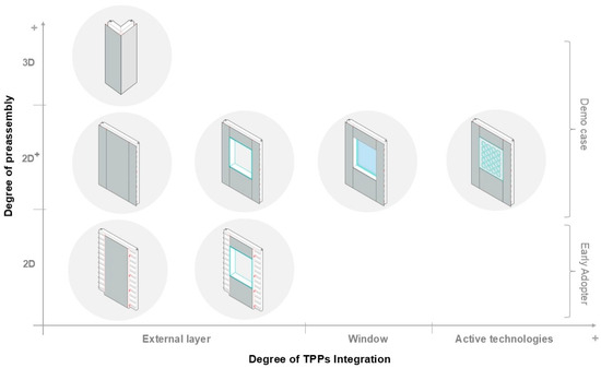 Figure 13. Categorisation of PnP modules’ configurations according to the level of preassembly and technological integration.
 - Role of PnP Technology Provider: The involvement of manufacturers is a key point to successfully implementing the PnP system. Their support was necessary from the design phase to the construction phase. The example of the two renovation scenarios underscores not only the need to involve the manufacturer from the early stages of the design phase but also the changes needed in the value chain when using such specialised technologies towards platforms in which manufacturers, builders, and designers are working together.
- Role of the Architect/Engineer: The two renovation scenarios highlighted the pivotal role of the designer in addressing the design of all the elements that cannot be industrialised and need on-site work, such as technical details between the PnP façade modules and the roof, or their integration with building services like waterspouts. Understanding the PnP technology by the designer is essential to developing all the remaining technical details to ensure a smooth and efficient construction process, guaranteeing envelope performance and time construction improvements.
4.2.1. Advantages of the PnP System
The two renovation scenarios in Budapest and Pamplona highlighted the following advantages of the PnP façade system:
- Thermal performance: The PnP module installation increased the building envelope’s thermal performance upon a correct installation, resulting in an improved thermal resistance of 4.348 m2K/W in Scenario 1 (improving the U-value from 1.77 W/m2K to 0.16 W/m2K) and 3.871 m2K/W in Scenario 2.
- Flexibility and customisation: The PnP façade proved to be adaptable to different contexts, offering a kit of modules’ configurations. This flexibility opens opportunities for its implementation in different contexts and climates. Integrating third-party products further enhances its mass customisation potential and multifunctionality, allowing for tailored solutions that meet specific project requirements.
- High-tech solution with a low level of understanding: The PnP system presents a high-tech solution characterised by its low complexity in terms of installation. The intuitive installation process allows the construction to be executed with the workers’ previous training.
- Safety environment in the factory for façade fabrication and workforce reduction: The controlled factory environment for facade fabrication reduces the workforce required on-site.
- On-site waste reduction: The assembly of PnP modules in a factory setting substantially reduces on-site waste (Table 9). The components are manufactured with precision, ensuring material efficiency and optimisation.
- Non-occupant disturbance: The PnP system allows work to be carried out on the building without disturbing the occupants, ensuring their regular activities are not disrupted, as demonstrated in Scenario 1.
4.2.2. Limitations of the PnP System
- Precision requirements: The installation of modules requires tolerances in the millimetre range. Therefore, accurate measurements are needed from the initial survey to the manufacturing and construction phases. Misalignments during the installation process, as observed in Scenario 1, can lead to further time-consuming adjustments. Investing more time in verifying building dimensions and out-of-plane to avoid on-site improvisation is necessary. Moreover, incorporating design adjustments, such as slightly larger tolerances in the module-to-frame interface, could be a strategy to accommodate minor discrepancies without compromising the overall installation quality, for example, a larger window hole to be completed with flared insulated flashes.
- Workers’ tolerance sensitiveness: Although the installation process is straightforward, the high precision required during the construction phase underscores the necessity for trained workers, particularly those experienced in steel construction. Unlike traditional building methods, where tolerances are forgiving, steel-based construction demands higher accuracy and expertise.
- Need for coordination protocols: As an innovative solution, the PnP system has revealed coordination challenges across the supply chain, emphasising enhanced communication and collaboration to address technical difficulties. Implementing a structured protocol during construction is essential to mitigate mistakes between the pre-design and the design phase. The protocols should clearly define guidelines, such as appropriate auxiliary tools, as incorrect equipment can increase execution times.
- Additional design and planning: Extra design and planning tasks are required to ensure compatibility and optimal integration of the PnP modules on the existing façade. This includes accommodating existing building features and integrating third-party products, which can be resource-intensive.
- Site constraints: The building’s surroundings must allow material storage and easy installation, including crane access and movement. This can be a limiting factor in dense urban environments where space is constrained. Adequate space for material handling is essential for smooth operations.
4.3. Limitations of the Study and Further Research Directions
This section discusses the study’s key findings and the advantages and limitations of the PnP technology. However, potential limitations need to be considered. First, the study was limited to two renovation scenarios, which do not fully capture the variability of the construction context; for example, the construction process in high-rise building applications needs to be explored. Second, the study addresses specific PnP technology in its advanced prototype phase, thus limiting the generalisability of the results regarding envelope performance and not allowing a fair cost estimation since the system is not fully developed, certified, or industrialised.
Future research should investigate the application of technology in challenging scenarios from the construction and performance requirements point of view. In this regard, integrating emerging technologies, such as advanced sensors for performance monitoring or building automation, represents a promising frontier to explore within the evolving context of predictive and cognitive buildings.
Further investigation is needed to analyse the technology’s thermal performance (through computational simulations and/or testing) and energy efficiency across a broader range of climatic conditions, thus contributing to structured, standardised installation protocols and ensuring consistent technological performance. Moreover, the impact of operating with a BIM-based approach during the overall renovation process has to be addressed, especially to meet the precision requirements affecting the execution from the pre-design to the execution phase. Additionally, research on improving the anchoring systems is necessary to reduce on-site practices and ease installation in terms of tolerance.
5. Conclusions
This work assessed the renovation process with a lightweight steel-based multifunctional PnP facade system in two different renovation scenarios—an early adopter building in Budapest and a demonstration case in Pamplona—offering practical insights and highlighting key advantages and limitations of the technology. The two applications underscored the system’s adaptability to different pre-existing statuses, revealing critical insights into the importance of precision in construction practices, workforce training, and improved coordination among architects, engineers, manufacturers, and construction companies.
The results demonstrate the potential of the PnP façade system to accelerate the renovation of the built environment, achieving an execution time rate of up to 11.74 m2/day in Scenario 2. With a higher level of PnP modules’ technological integration, the second renovation scenario has demonstrated a faster execution time than Scenario 1, which served as an early adopter, providing room for improvement developed in the second scenario. Regarding the thermal performance, the PnP module installation increased the building envelope’s thermal resistance of 4.348 m2K/W in Scenario 1 (improving the U-value from 1.77 W/m2K to 0.16 W/m2K) and 3.871 m2K/W in Scenario 2.
The data collected related to the construction time rate confirm the potential of the PnP system through the solution’s benchmarking regarding reduced labour performance and waste production compared to the available database data of similar conventional renovation systems, such as a ventilated façade. This study contributes to further refinement of the PnP façade system, paving the way for scalable solutions to support decarbonisation objectives in the broader framework of off-site construction.
Author Contributions
Conceptualisation, G.M. and D.M.V.; methodology, G.M.; investigation, G.M., D.M.V., I.R.R. and M.I.-P.; data curation and analysis, G.M. and D.M.V.; writing—original draft preparation, G.M. and D.M.V.; writing—review and editing, G.M. and D.M.V.; visualisation, G.M. and D.M.V.; supervision, I.R.R., M.L. and R.T. All authors have read and agreed to the published version of the manuscript.
Funding
This research was funded by the EUROPEAN UNION’S HORIZON 2020, grant number 847053.
Institutional Review Board Statement
Not applicable.
Informed Consent Statement
Not applicable.
Data Availability Statement
Data are contained within the article.
Acknowledgments
The content presented in this contribution results from close collaboration between various research partners. Acknowledgements belong to MANNI GROUP for the technical design of the Plug-and-Play (PnP) module and the building of all the full-scale prototypes and ISOPAN for providing the sandwich panels. Acknowledgments to the municipality of Budapest, BP18, for providing the pilot and its active role in the project, and to the ‘‘Escuela Técnica Superior de ’Arquitectura’” of the University of Navarra for their collaboration in the development of the Spanish pilot; ONYX Solar and COPERMO for providing the photovoltaic panel and the high-performance windows integrated into the renovation scenarios, respectively. The authors thank the StepUP consortium for contributing to the project development. Specifically, acknowledgements go to Giulia Barbano and Amisha Panchal as project coordinators, ACR for conducting and bringing their experience on the construction of the Spanish pilot, and EURECAT for setting up the third-party products to be included in the Plug-and-Play module.
Conflicts of Interest
Authors Marta Lupi and Rocco Traini were employed by Isopan. Author Irene Rafols Ribas were employed by Eurecat. Author Maria Ibañez Puy was employed by Construcciones ACR. The remaining authors declare that the research was conducted in the absence of any commercial or financial relationships that could be construed as a potential conflict of interest.
References
- Mackay, A. Climate Change 2007: Impacts, Adaptation and Vulnerability. Contribution of Working Group II to the Fourth Assessment Report of the Intergovernmental Panel on Climate Change. J. Environ. Qual. 2008, 37, 2407. [Google Scholar] [CrossRef]
- McMichael, A.J.; Woodruff, R.E.; Hales, S. Climate change and human health: Present and future risks. Lancet 2006, 367, 859–869. [Google Scholar] [CrossRef] [PubMed]
- Stern, N. The Economics of Climate Change: The Stern Review; Cambridge University Press: Cambridge, UK, 2007. [Google Scholar] [CrossRef]
- European Commission. European Green Deal: Circular Economy Action Plan for a Cleaner and More Competitive Europe; European Union: Brussels, Belgium, 2020.
- IPCC. Summary for Policymakers. In Climate Change 2013—The Physical Science Basis; Cambridge University Press: Cambridge, UK, 2013; Available online: https://www.cambridge.org/core/books/abs/climate-change-2013-the-physical-science-basis/summary-for-policymakers/356E277FD1FBC887845FB9E8CBC90CCD (accessed on 19 February 2025).
- European Commission: Directive 2024/1275 on the Energy Performance of Buildings. 2024. Available online: https://eur-lex.europa.eu/legal-content/EN/TXT/?uri=OJ:L_202401275&pk_keyword=Energy&pk_content=Directive (accessed on 1 July 2024).
- European Commission: Directive 2023/1791 on Energy Efficiency and Amending Regulation (EU) 2023/955 (Recast). 2023. Available online: https://eur-lex.europa.eu/legal-content/EN/TXT/?uri=OJ%3AJOL_2023_231_R_0001&qid=1695186598766 (accessed on 1 July 2024).
- Buildings—Energy System—IEA. Available online: https://www.iea.org/energy-system/buildings (accessed on 24 April 2024).
- Laxmi, H.; Alex, C.; Caspar, D.; Marc, D.W.; Jelmer, H. The Circularity Gap Report 2021. 2021. Available online: https://www.circularity-gap.world/2021#downloads (accessed on 19 February 2025).
- Renovation Wave: Revision of EPBD and EED—Renovate Europe. Available online: https://www.renovate-europe.eu/renovation-wave/ (accessed on 28 April 2024).
- Zangheri, P.; Castellazzi, L.; D’Agostino, D.; Economidou, M.; Ruggieri, G.; Tsemekidi-Tzeiranaki, S.; Maduta, C.; Bertoldi, P. Progress of the Member States in Implementing the Energy Performance of Building Directive; Publications Office of the EU: Luxembourg, 2021. [Google Scholar] [CrossRef]
- European Commission: Factsheet Renovation Wave Initiative. 2020. Available online: https://op.europa.eu/en/publication-detail/-/publication/828f43b8-4596-11eb-b59f-01aa75ed71a1/language-en (accessed on 19 February 2025).
- European Commission. Renovation Wave. Available online: https://energy.ec.europa.eu/topics/energy-efficiency/energy-efficient-buildings/renovation-wave_en (accessed on 19 February 2025).
- EUR-Lex—52020DC0662—EN—EUR-Lex. Available online: https://eur-lex.europa.eu/legal-content/EN/TXT/?qid=1603122220757&uri=CELEX:52020DC0662 (accessed on 29 April 2024).
- Broer, R.; Dravecký, L.; Fabbri, M.; Fernández Álvarez, X.; Kockat, J.; Jankovic, I.; Jeffries, B.; Milne, C.; Rapf, O. Deep Renovation: Shifting from Exception to Standard Practice in EU Policy; Buildings Performance Institute Europe: Brussels, Belgium, 2021. [Google Scholar]
- Österbring, M.; Camarasa, C.; Nägeli, C.; Thuvander, L.; Wallbaum, H. Prioritizing deep renovation for housing portfolios. Energy Build. 2019, 202, 109361. [Google Scholar] [CrossRef]
- Joyce, A.; Higgins, C.; Staniaszek, D.; Wiggington, L. What is a Deep Renovation Definition? Expert Input Photo Credits Cover Photo © GBPN EXECUTIVE SUMMARY 6! Existing Buildings Mitigation Potential by Renovating Deeply 6! Webinars and Questionnaire-Methodology 6! 2013. Available online: https://www.gbpn.org/wp-content/uploads/2021/06/08.DR_TechRep.low_.pdf (accessed on 19 February 2025).
- Jin, R.; Gao, S.; Cheshmehzangi, A.; Aboagye-Nimo, E. A holistic review of off-site construction literature published between 2008 and 2018. J. Clean Prod. 2018, 202, 1202–1219. [Google Scholar] [CrossRef]
- Capeluto, G. Adaptability in envelope energy retrofits through addition of intelligence features. Archit. Sci. Rev. 2019, 62, 216–229. [Google Scholar] [CrossRef]
- Van Oorschot, J.; Di Maggio, M.S.; Op‘t Veld, P.; Tisov, A. Boosting the Renovation Wave with Modular Industrialized Renovation Kits: Mapping Challenges, Barriers and Solution Strategies. 2022. Available online: https://circulareconomy.europa.eu/platform/en/knowledge/boosting-renovation-wave-modular-industrialized-renovation-kits-mapping-challenges-barriers-and-solution-strategies (accessed on 1 July 2024).
- Hosseini, M.R.; Martek, I.; Zavadskas, E.K.; Aibinu, A.A.; Arashpour, M.; Chileshe, N. Critical evaluation of off-site construction research: A Scientometric analysis. Autom. Constr. 2018, 87, 235–247. [Google Scholar] [CrossRef]
- D’Oca, S.; Ferrante, A.; Ferrer, C.; Pernetti, R.; Gralka, A.; Sebastian, R.; op ‘t Veld, P. Technical, Financial, and Social Barriers and Challenges in Deep Building Renovation: Integration of Lessons Learned from the H2020 Cluster Projects. Buildings 2018, 8, 174. [Google Scholar] [CrossRef]
- Lou, N.; Guo, J. Study on Key Cost Drivers of Prefabricated Buildings Based on System Dynamics. Adv. Civ. Eng. 2020, 2020, 8896435. [Google Scholar] [CrossRef]
- Agapiou, A. Barriers to Offsite Construction Adoption: A Quantitative Study among Housing Associations in England. Buildings 2022, 12, 283. [Google Scholar] [CrossRef]
- Looby, K.H.; Smith, S.T.; Shahrestani, M. Attitudes towards offsite prefabrication: A fuzzy approach to examining uncertainty within U.K. industry perception. Intell. Build. Int. 2022, 14, 738–752. [Google Scholar] [CrossRef]
- Basso, P.; Mililli, M.; Herrero, F.J.M.; Sanz, R.; Casaldiga, P. E2VENT—Design and integration of an adaptable module for residential building renovation. J. Facade Des. Eng. 2017, 5, 7–23. [Google Scholar] [CrossRef]
- Op ‘t Veld, P. MORE-CONNECT: Development and Advanced Prefabrication of Innovative, Multifunctional Building Envelope Elements for Modular Retrofitting and Smart Connections. Energy Procedia 2015, 78, 1057–1062. [Google Scholar] [CrossRef]
- Refurbishment Solutions|STUNNING. Available online: https://renovation-hub.eu/refurbishment-solutions/ (accessed on 1 April 2024).
- Giovanardi, M.; Baietta, A.; Belletti, F.; Magnani, S.; Casadei, O.; Pracucci, A. Exploiting the Value of Active and Multifunctional Façade Technology through the IoT and AI. Appl. Sci. 2024, 14, 1145. [Google Scholar] [CrossRef]
- Loga, T.; Stein, B.; Diefenbach, N. TABULA building typologies in 20 European countries—Making energy-related features of residential building stocks comparable. Energy Build. 2016, 132, 4–12. [Google Scholar] [CrossRef]
- TABULA WebTool. Available online: https://webtool.building-typology.eu/#bm (accessed on 1 July 2024).
- Lihtmaa, L.; Kalamees, T. Emerging renovation strategies and technical solutions for mass-construction of residential districts built after World War II in Europe. Energy Strategy Rev. 2024, 51, 101282. [Google Scholar] [CrossRef]
- Founti, M.; Avesani, S.; Esnarrizaga, P.E. Multifunctional Façades for Renovation Through Industrialization. J. Facade Des. Eng. 2023, 11, V. [Google Scholar] [CrossRef]
- OVERVIEW|Modular and Industrialised Solutions for Building Renovation|BUILD UP. Available online: https://build-up.ec.europa.eu/en/resources-and-tools/articles/overview-modular-and-industrialised-solutions-building-renovation (accessed on 1 July 2024).
- Katsigiannis, E.; Gerogiannis, P.; Atsonios, I.A.; Manolitsis, A.; Founti, M. SmartWall: Towards residential nZEB with off-site prefabricated hybrid façade systems using a variety of materials. J. Facade Des. Eng. 2023, 11, 029–050. [Google Scholar] [CrossRef]
- Piaia, E.; Turillazzi, B.; Longo, D.; Boeri, A.; Giulio, R. Di: Plug-and-Play and innovative process technologies (Mapping/Modelling/Making/Monitoring) in deep renovation interventions. TECHNE—J. Technol. Archit. Environ. 2019, 18, 215–225. [Google Scholar] [CrossRef]
- Sebastian, R.; Gralka, A.; Olivadese, R.; Arnesano, M.; Revel, G.M.; Hartmann, T.; Gutsche, C. Plug-and-Play Solutions for Energy-Efficiency Deep Renovation of European Building Stock. Proceedings 2018, 2, 1157. [Google Scholar] [CrossRef]
- Orova, M.; Reith, A. Improved methodology for affordable, reliable deep building renovations. IOP Conf. Ser. Earth Environ. Sci. 2022, 1085, 012003. [Google Scholar] [CrossRef]
- Goulding, J.S.; Pour Rahimian, F.; Arif, M.; Sharp, M.D. New offsite production and business models in construction: Priorities for the future research agenda. Archit. Eng. Des. Manag. 2015, 11, 163–184. [Google Scholar] [CrossRef]
- Iturralde, K.; Linner, T.; Bock, T. Development of a modular and integrated product manufacturing-installation system kit for the automation of the refurbishment process in the research project BERTIM. In Proceedings of the ISARC 2016—33rd International Symposium on Automation and Robotics in Construction, Auburn, AL, USA, 18–21 July 2016. [Google Scholar] [CrossRef]
- 4RinEU. Available online: https://www.4rineu.eu/ (accessed on 1 August 2024).
- Vavallo, M.; Arnesano, M.; Revel, G.M.; Mediavilla, A.; Sistiaga, A.F.; Pracucci, A.; Magnani, S.; Casadei, O. Accelerating Energy Renovation Solution for Zero Energy Buildings and Neighbourhoods—The Experience of the RenoZEB Project. Proceedings 2019, 20, 1. [Google Scholar] [CrossRef]
- Torres, J.; Garay-Martinez, R.; Oregi, X.; Torrens-Galdiz, J.I.; Uriarte-Arrien, A.; Pracucci, A.; Casadei, O.; Magnani, S.; Arroyo, N.; Cea, A.M. Plug and play modular façade construction system for renovation for residential buildings. Buildings 2021, 11, 419. [Google Scholar] [CrossRef]
- Accelerating Energy Renovation Solution for Zero Energy Buildings and Neighbourhoods. Available online: https://cordis.europa.eu/project/id/768718/results/es (accessed on 1 February 2025).
- Gubert, M.; Ngoyaro, J.A.; Gutierrez, M.J.; Pinotti, R.; Brandolini, D.; Avesani, S. Comparative cost analysis of traditional and industrialised deep retrofit scenarios for a residential building. J. Facade Des. Eng. 2023, 11, 145–168. [Google Scholar] [CrossRef]
- PLURAL. Available online: https://www.plural-renovation.eu/ (accessed on 1 July 2024).
- Katsigiannis, E.; Gerogiannis, P.A.; Atsonios, I.; Bonou, A.; Mandilaras, I.; Georgi, A.; Papadopoulou, S.; Tsoutis, C.; Founti, M. Energy assessment of a residential building renovated with a novel prefabricated envelope integrating HVAC components. IOP Conf. Ser. Earth Environ. Sci. 2022, 1078, 012130. [Google Scholar] [CrossRef]
- Katsigiannis, E.; Gerogiannis, P.A.; Atsonios, I.; Mandilaras, I.; Founti, M. Design and Parametric Analysis of a Solar-Driven Façade Active Layer System for Dynamic Insulation and Radiant Heating: A Renovation Solution for Residential Buildings. Energies 2023, 16, 5134. [Google Scholar] [CrossRef]
- Dias Pereira, L.; Raimondo, D.; Corgnati, S.P.; Gameiro Da Silva, M. Energy consumption in schools—A review paper. Renew. Sustain. Energy Rev. 2014, 40, 911–922. [Google Scholar] [CrossRef]
- Masip, D.; Marrone, G.; Rafols, I. Implementation of a multifunctional Plug-and-Play façade using a set-based design approach. J. Facade Des. Eng. 2023, 11, 071–096. [Google Scholar] [CrossRef]
- ISO 13786:2018; Thermal Performance of Building Components—Dynamic Thermal Characteristics—Calculation Methods. ISO: Geneva, Switzerland, 2018.
- Commission Decision of 3 May 2000 Establishing a List of Wastes. Available online: https://eur-lex.europa.eu/legal-content/EN/TXT/?uri=CELEX:02000D0532-20150601 (accessed on 19 January 2025).
- Kottek, M.; Grieser, J.; Beck, C.; Rudolf, B.; Rubel, F. World map of the Köppen-Geiger climate classification updated. Meteorol. Z. 2006, 15, 259–263. [Google Scholar] [CrossRef]
- StepUP Project: Deliverable D5.6: Final Report on Monitoring and Adjustment. 2024. Available online: https://www.stepup-project.eu/download/d5-6-final-report-on-monitoring-and-adjustment-part-1-2/ (accessed on 19 February 2025).
- EN 13501-1; Fire Classification of Construction Products and Building Elements—Part 1: Classification Using Data from Reaction to Fire Tests. EU Standard: Brussels, Belgium, 2019.
- Marrone, G.; Sesana, M.M.; Imperadori, M. Life-cycle assessment of light steel frame buildings: A systematic literature review. In Life-Cycle of Structures and Infrastructure Systems: Proceedings of the Eighth International Symposium on Life-Cycle Civil Engineering (IALCCE 2023), Milan, Italy, 2–6 July 2023, 1st ed.; Biondini, F., Frangopol, D.M., Eds.; CRC Press: Boca Raton, FL, USA, 2023; pp. 2405–2412. [Google Scholar] [CrossRef]
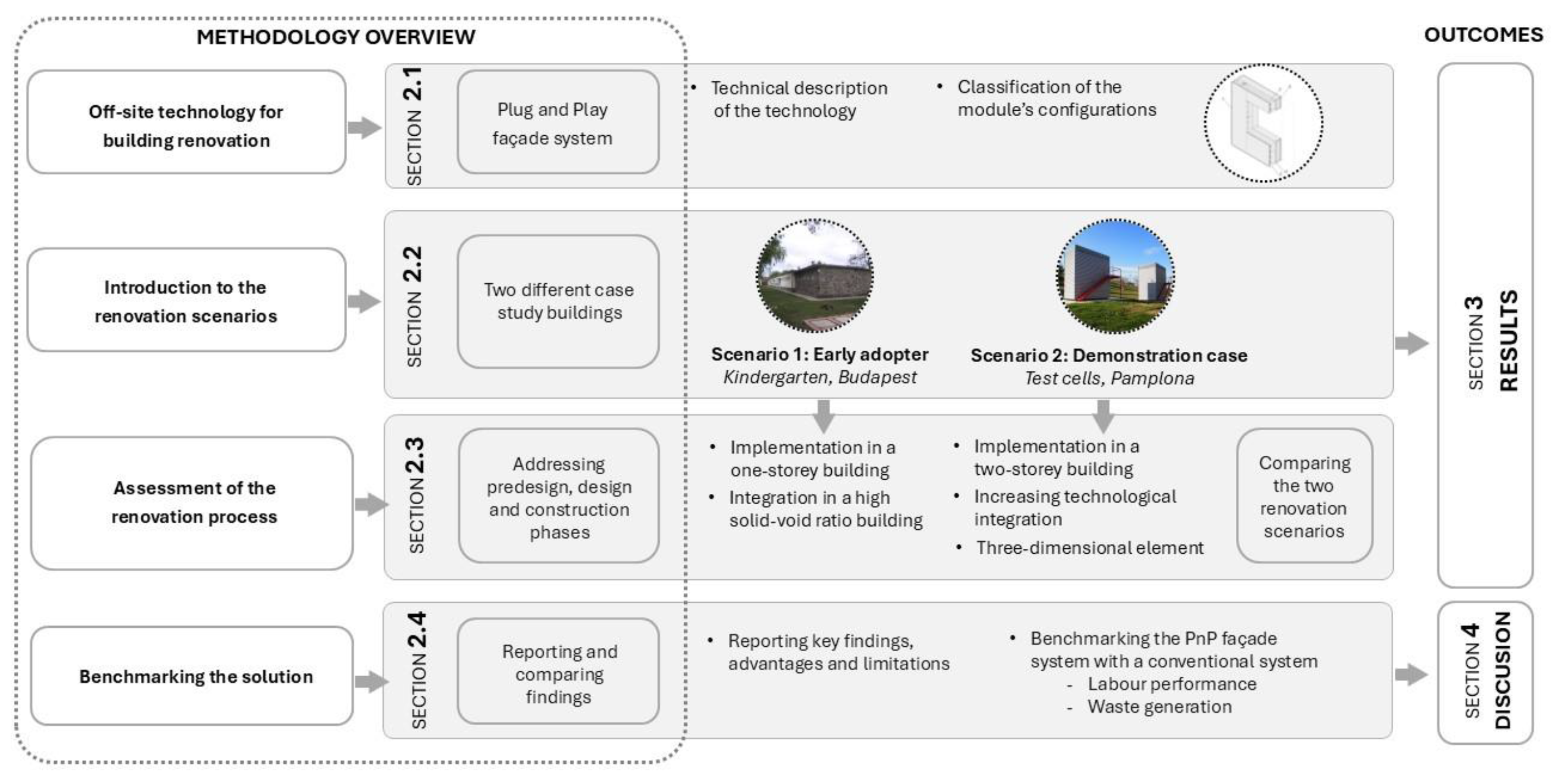
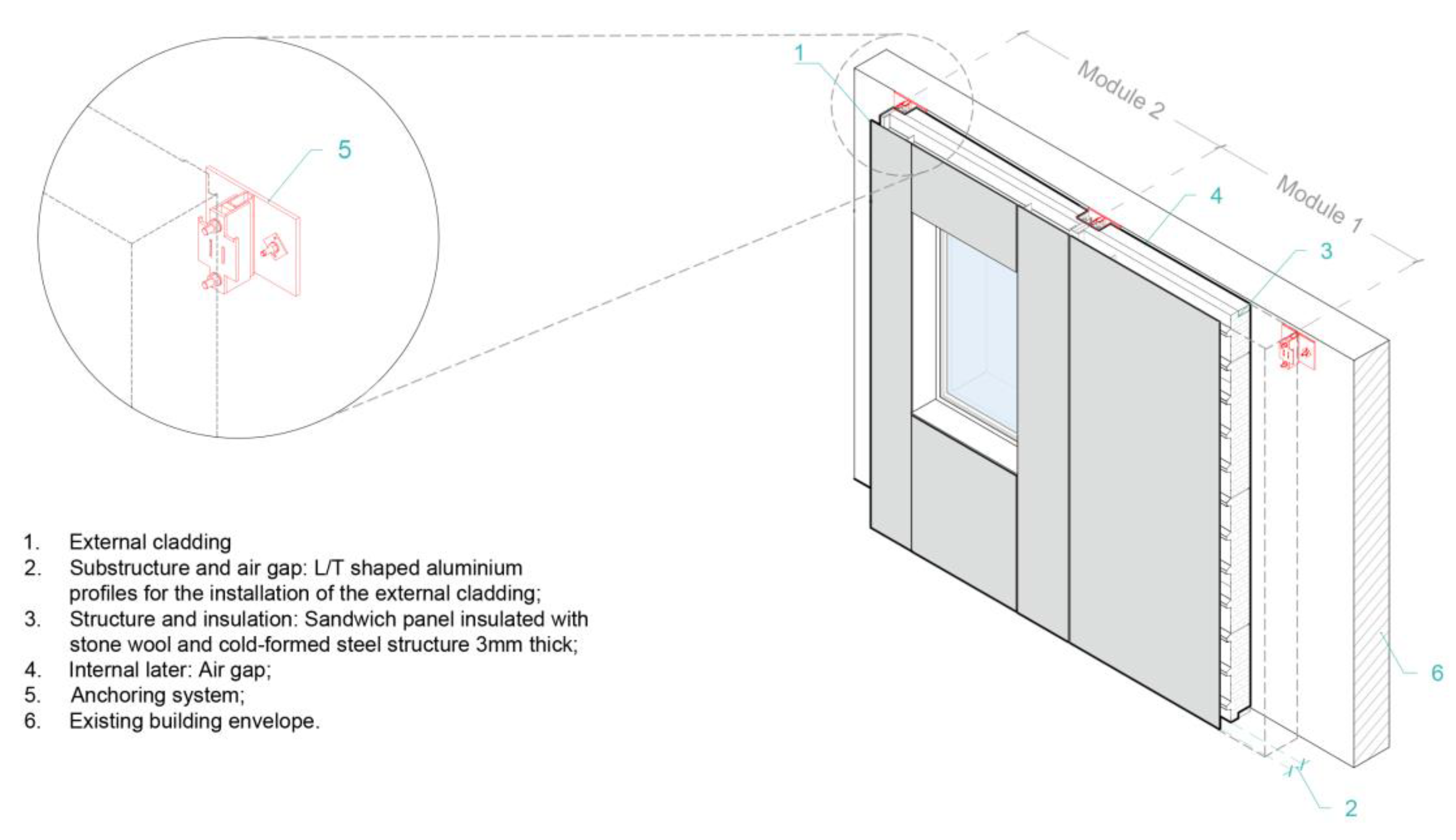
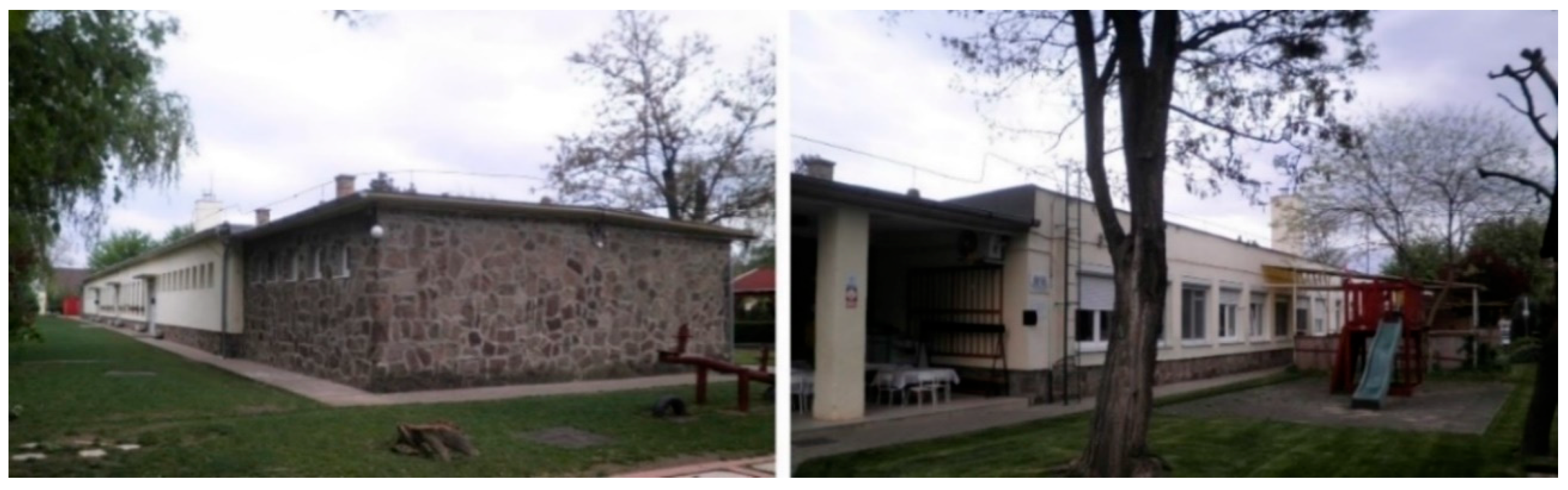

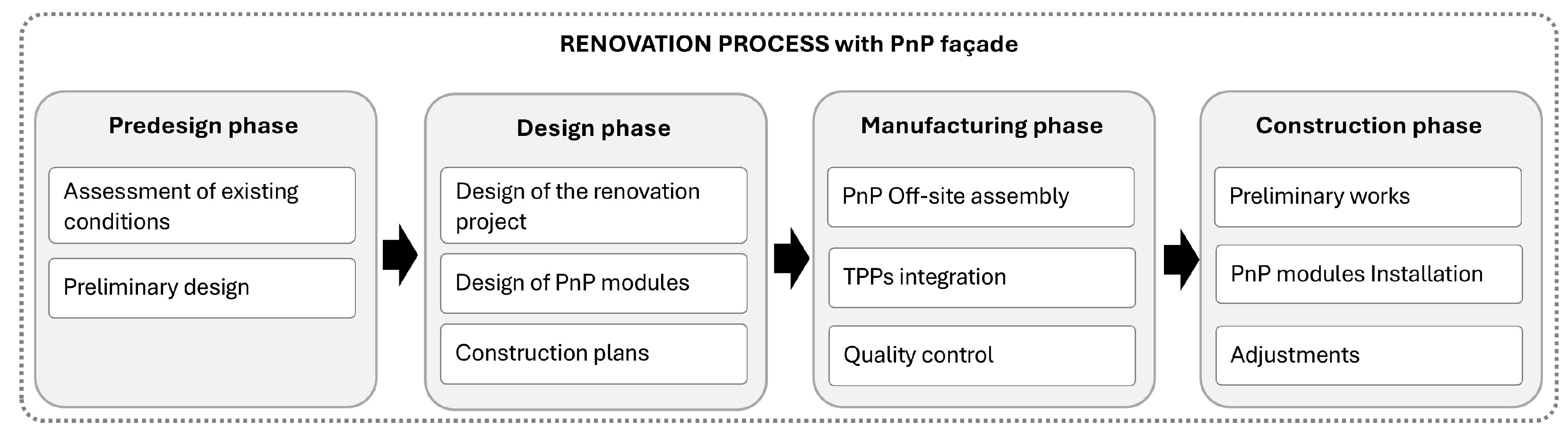


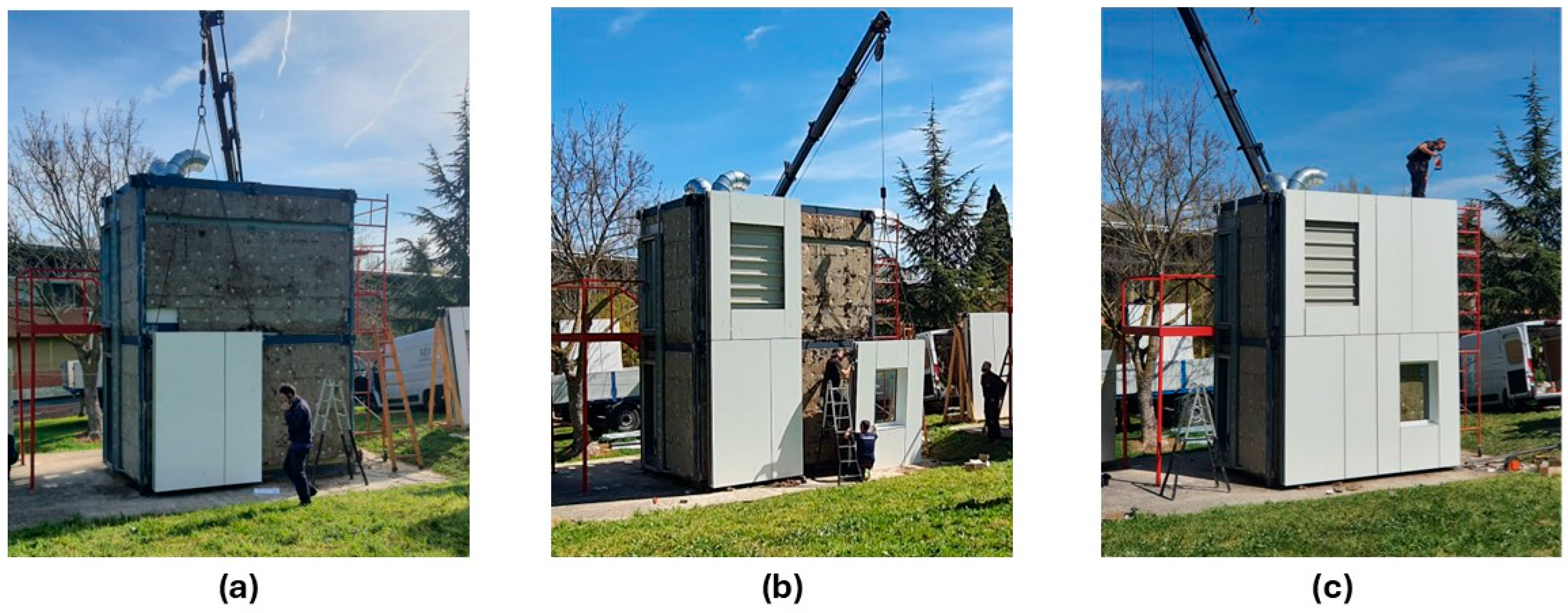

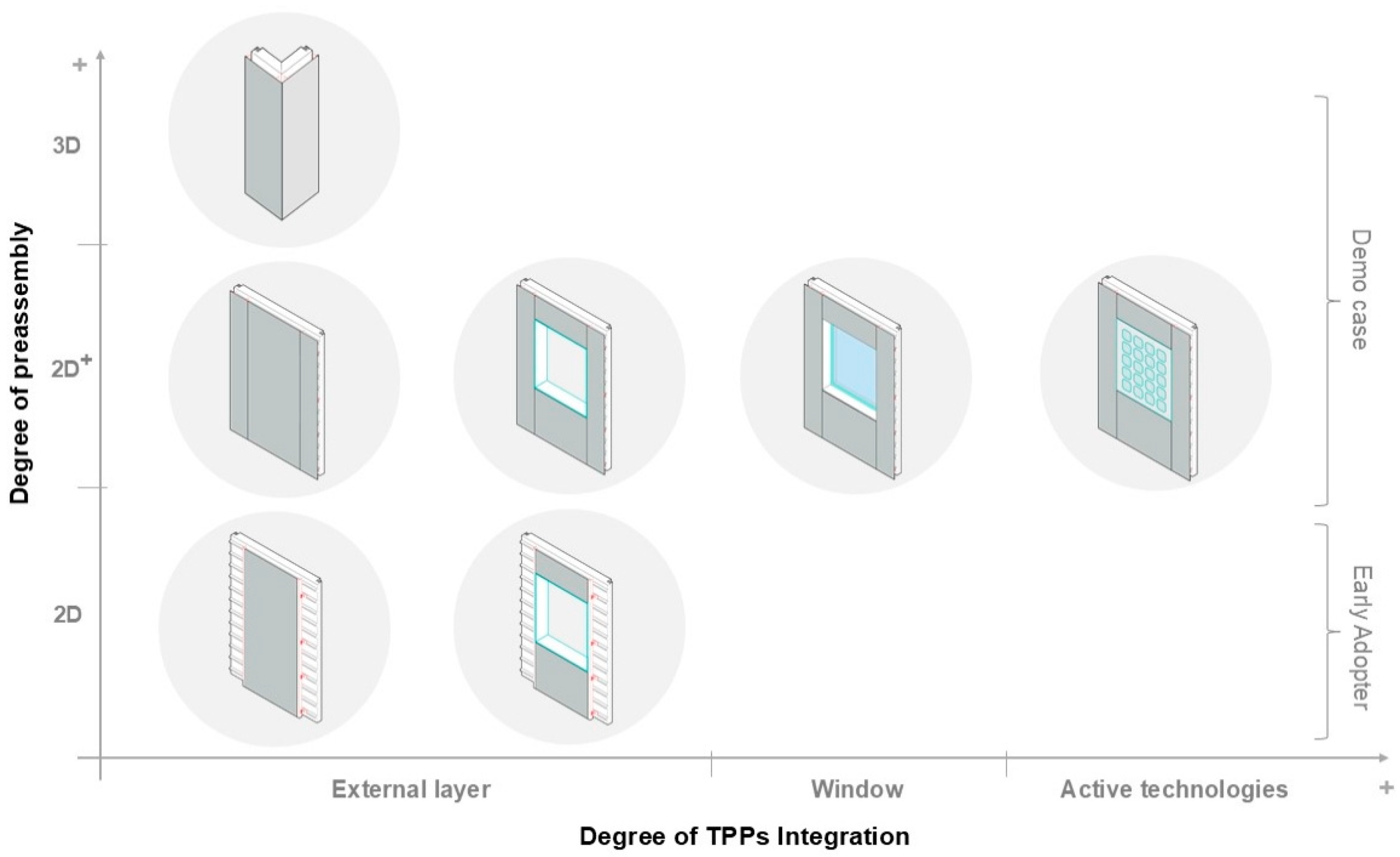
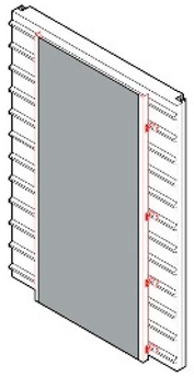
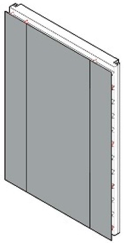
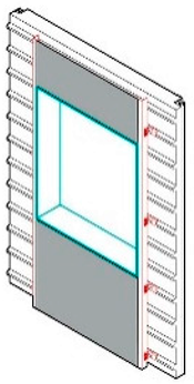
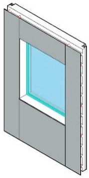
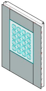
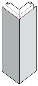
Disclaimer/Publisher’s Note: The statements, opinions and data contained in all publications are solely those of the individual author(s) and contributor(s) and not of MDPI and/or the editor(s). MDPI and/or the editor(s) disclaim responsibility for any injury to people or property resulting from any ideas, methods, instructions or products referred to in the content. |
© 2025 by the authors. Licensee MDPI, Basel, Switzerland. This article is an open access article distributed under the terms and conditions of the Creative Commons Attribution (CC BY) license (https://creativecommons.org/licenses/by/4.0/).