

Research on the Optimized Design of Medium and Deep Ground-Source Heat Pump Systems Considering End-Load Variation

Abstract
:1. Introduction
2. Numerical Modelling and Computational Methods
2.1. Calculation Model Fluency
2.2. Model Assumptions
- (1)
- The surface temperature is assumed to remain constant, and the effects of subsurface seepage are disregarded. Consequently, geotechnical heat transfer is modelled as a purely thermal conduction process. This assumption holds for regions with minimal seepage effects, significantly simplifying the coupled convection–heat conduction model and ensuring computational efficiency without compromising the simulation accuracy of heat-transfer behaviour.
- (2)
- Stratigraphy with similar lithologies is combined and modelled as a homogeneous horizontally layered structure, which serves as the basis of the model. This simplification reduces the complexity of stratigraphic zoning while retaining the essential effects of major thermophysical differences and is commonly used in studies under similar geological conditions.
- (3)
- The initial temperatures of the fluid in the casing, the backfill material, and the buried pipe are assumed to match the same horizontal geotechnical temperature, and the measured soil temperature is assumed to be uniform. This setting is based on the thermal equilibrium state, which accurately represents the initial thermal coupling relationship between the system and the geotechnical soil and simplifies the specification of the initial conditions.
2.3. Calculation Method
2.4. Fixed Solution Conditions
2.5. Model Validation
3. Results and Analyses
3.1. Effects of Well Depth and the Internal-to-External Pipe Diameter Ratio
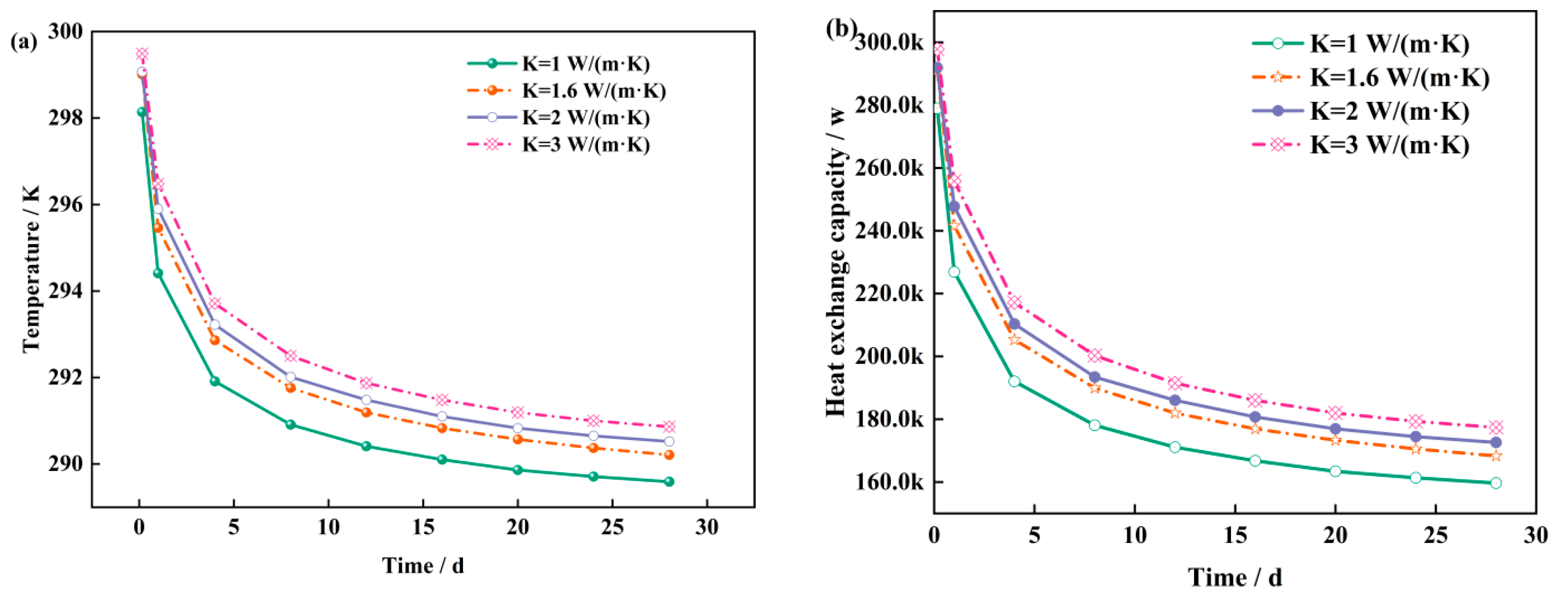
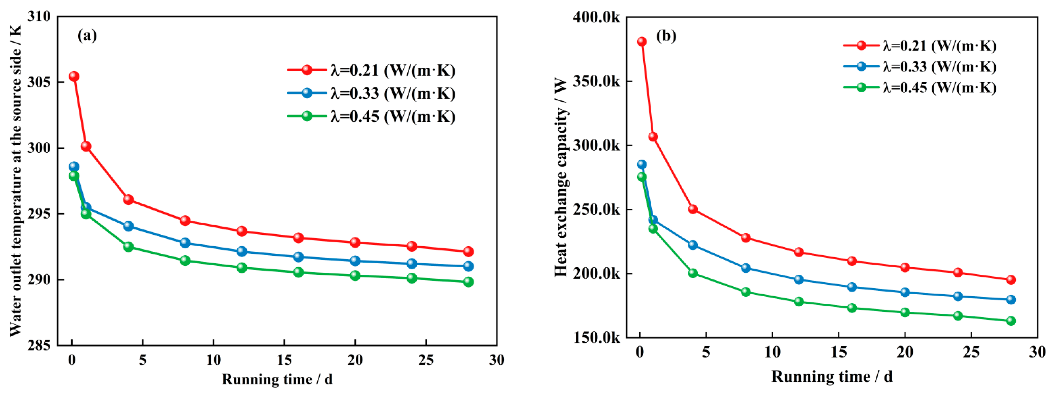
3.2. Effects of the Thermal Conductivity of the Cementing Cement and the Thermal Conductivity of the Inner Tubes
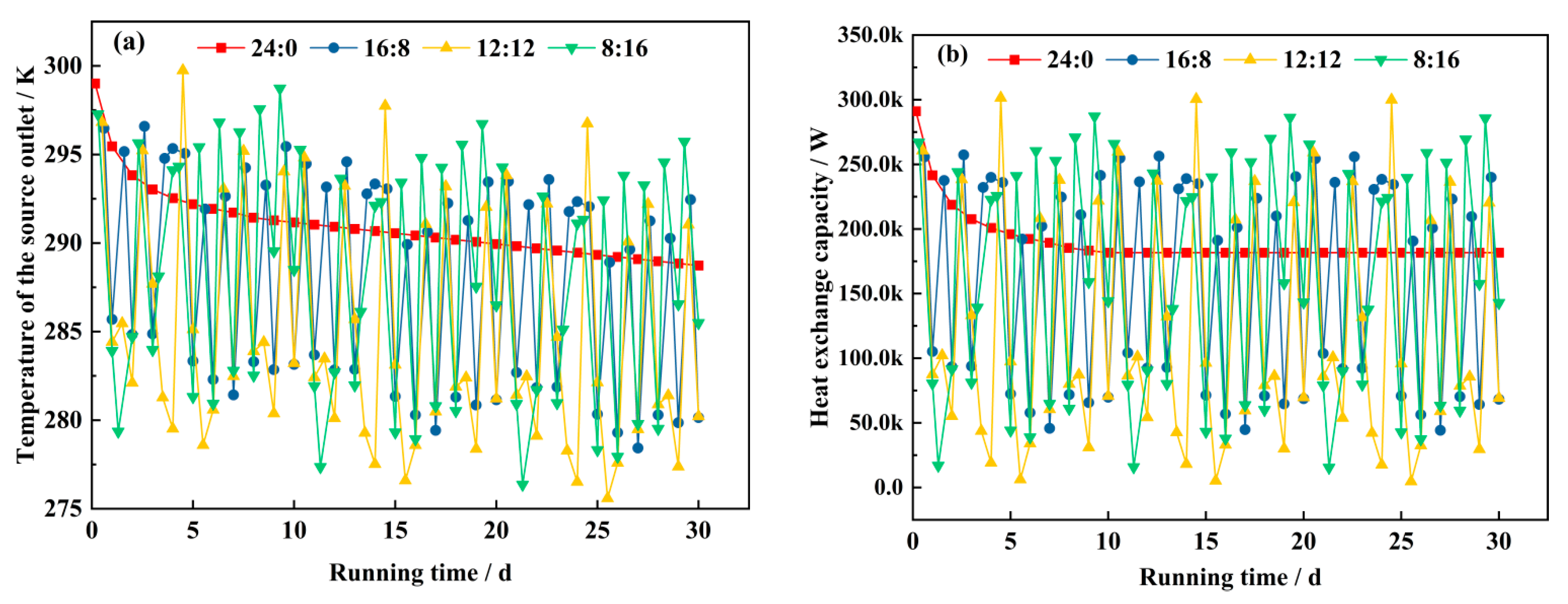
3.3. Effects of Variations in the Flow Rate and Start–Stop Ratio
4. Discussion
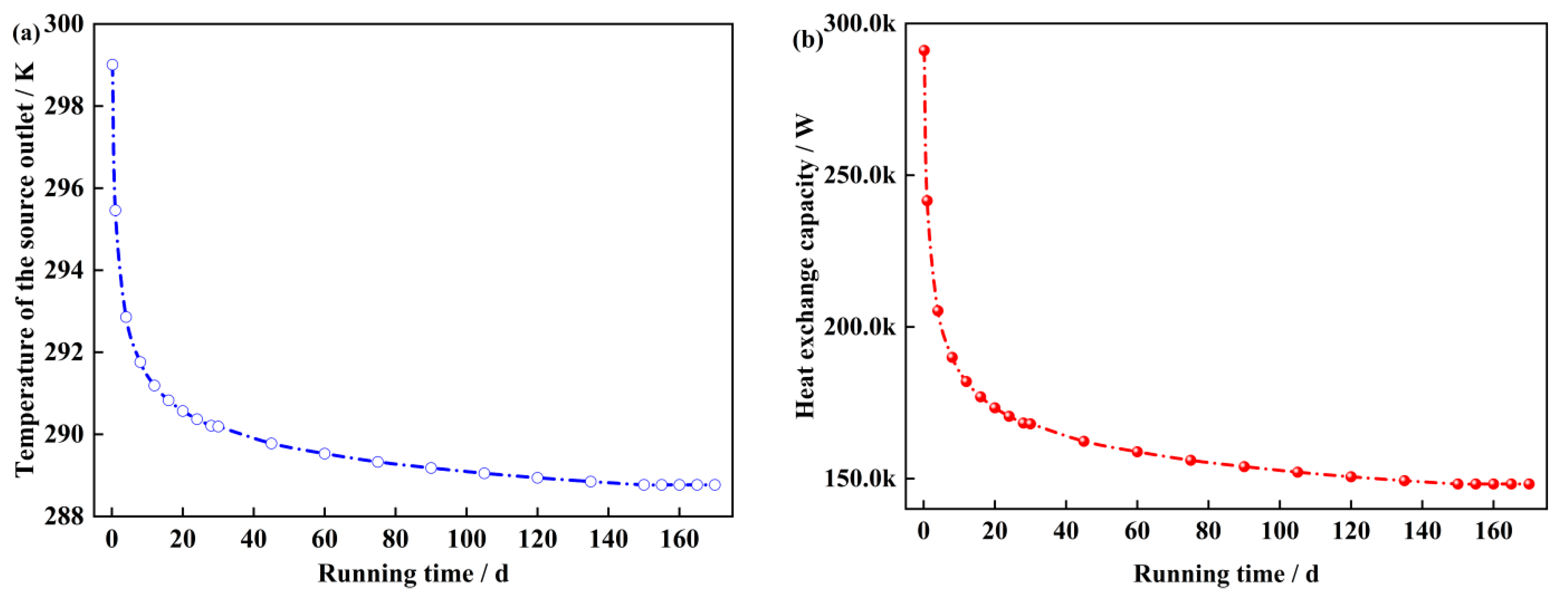
4.1. Analysis of the Heat-Transfer Characteristics of the Radial Geotechnical Body on the Source Side During Full Heating Cycle Operation
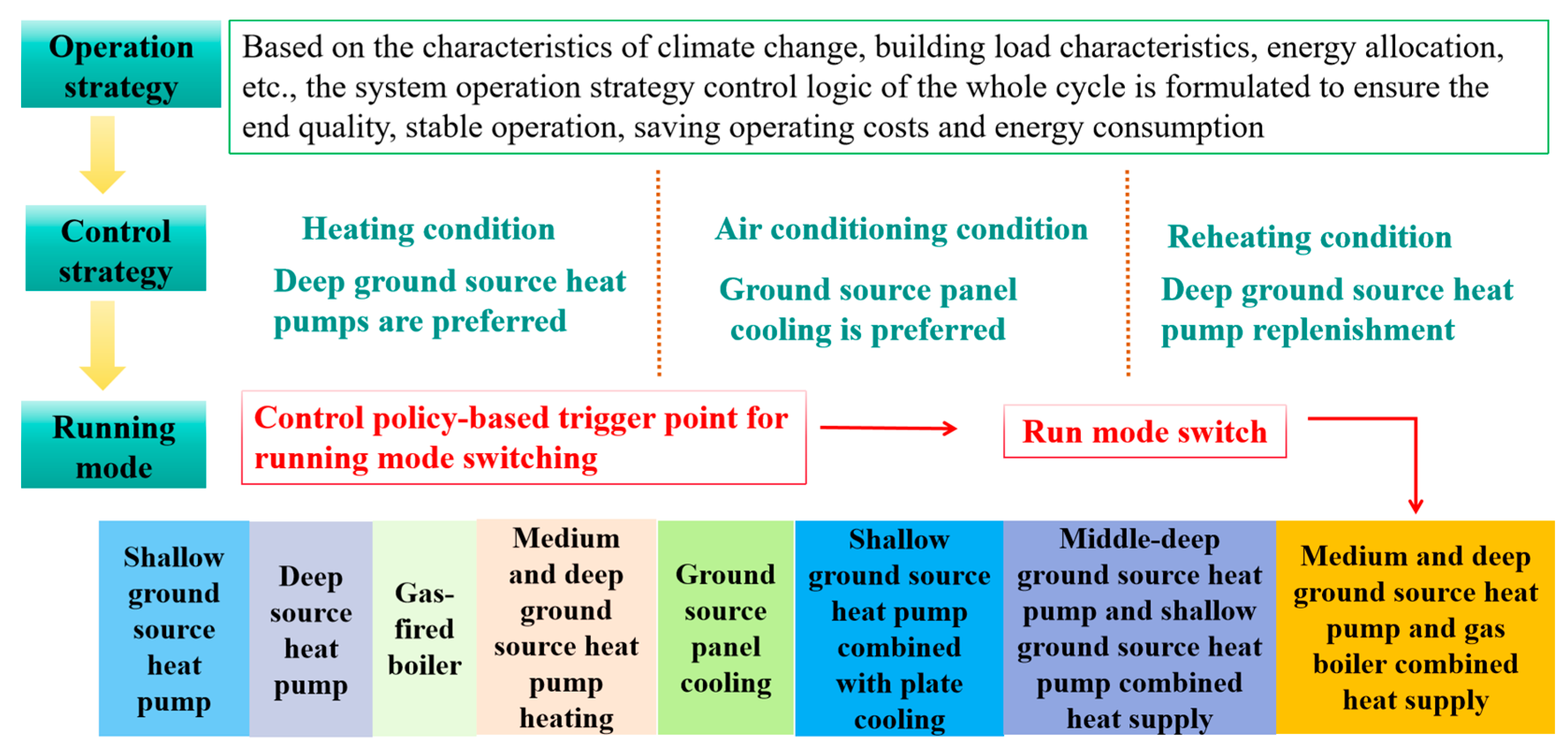
4.2. Joint Operational Control Analysis Based on Year-Round Dynamic Simulation
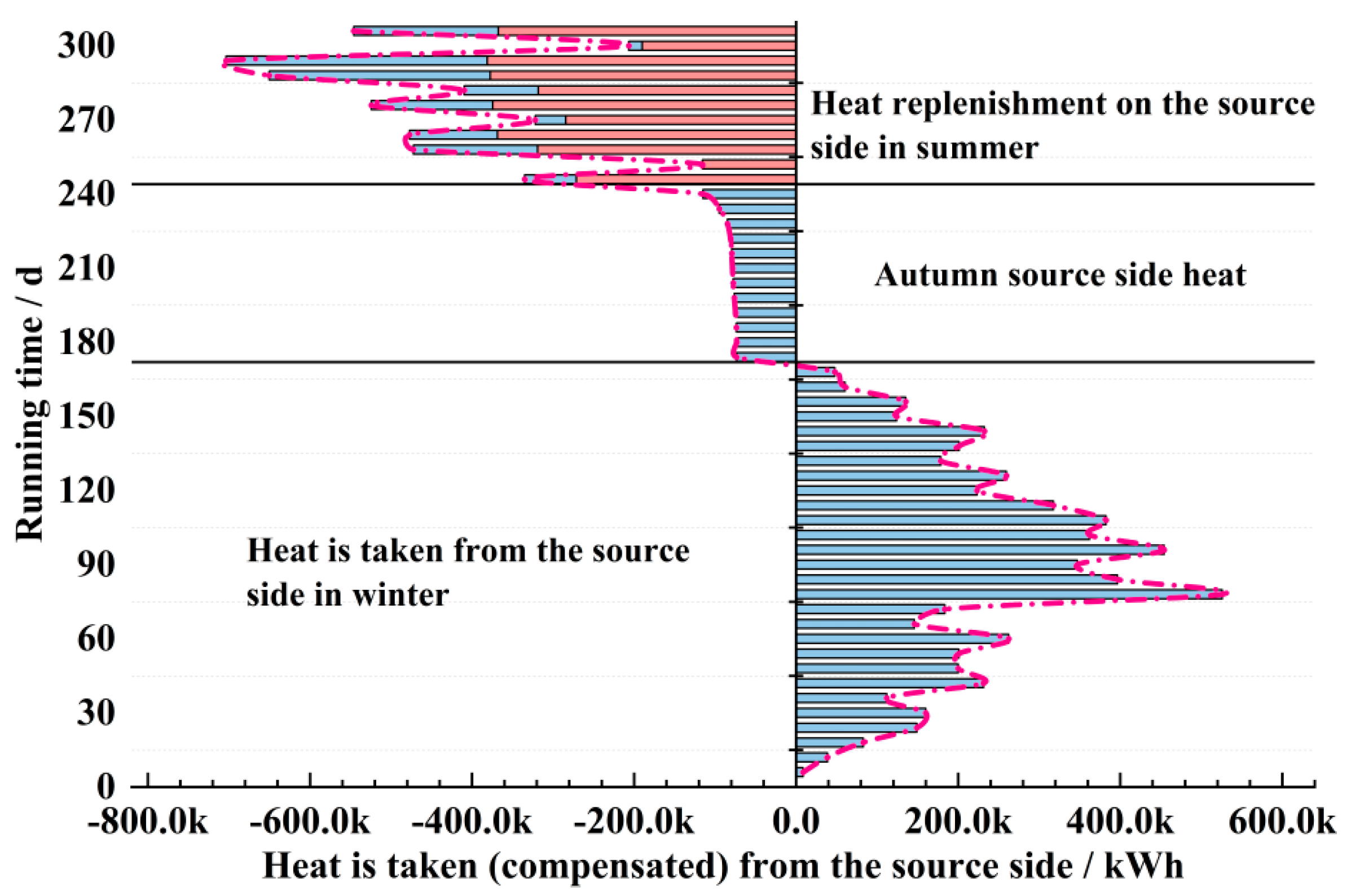
4.3. Load-Side and Source-Side Heat Balance Analyses That Are Based on the Control Strategy
5. Conclusions
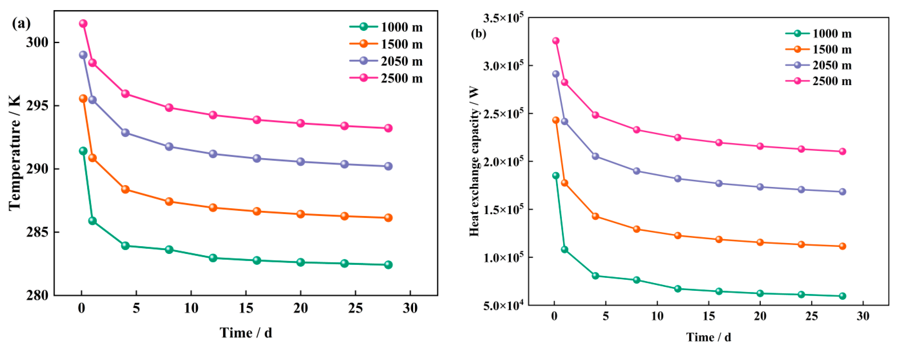
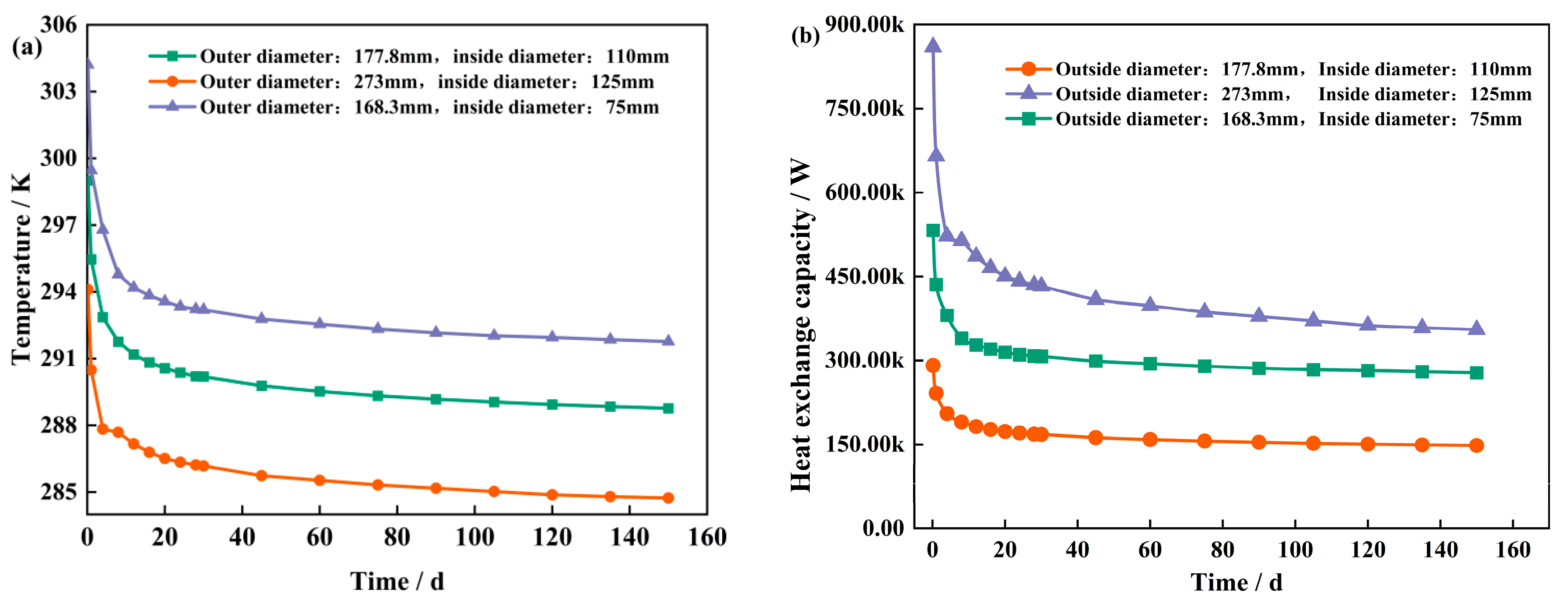
- (1)
- Increasing the well depth significantly enhances the utilization efficiency of the underground heat storage resources, with a 50 kW increase in heat-transfer capacity for every 500 m increase in well depth, demonstrating a linear growth trend. Additionally, optimizing the internal-to-external pipe diameter ratio effectively enhances the heat-exchange capacity between the fluid and the geotechnical body. The appropriate selection of a larger pipe diameter ratio can significantly reduce the flow resistance and improve the system heat-exchange efficiency.
- (2)
- When the thermal conductivity of cement is close to that of rock and soil, the heat-transfer performance is significantly improved. Specifically, when the thermal conductivity of the cementing cement increases from 1 W/(mK) to 2 W/(mK), the water outlet temperature on the source side increases by approximately 1 °C, and the heat change increases by 13 kW. However, the gain in system efficiency gradually increases. Although an increase in the thermal conductivity of the inner tube can increase the heat transfer rate, it may cause a thermal short-circuit effect and then have a negative impact on the outlet temperature. Therefore, optimizing the thermal conductivity should consider the balance between thermal performance and heat loss to maximize the overall efficiency of the system.
- (3)
- The flow rate has a significant effect on the initial increase in the heat exchange of the system, but with time, the heat transfer effect tends to be saturated. When the operating flow rate is controlled at 0.7 m/s, the heat change is stable at approximately 250 kW, and the system economy can be optimized under the premise of ensuring efficient heat exchange. The adjustment of the start–stop ratio not only improves the energy consumption distribution of the system but also effectively optimizes the long-term thermal balance of the system by strengthening the thermal compensation capacity, which is especially suitable for heating scenarios with large load fluctuations.
- (4)
- The heat release rate of the geotechnical body is high during initial system operation. However, as the heating cycle progresses, the geotechnical body’s heat balance capability gradually emerges, and the outlet temperature and heat-exchange volume stabilize, demonstrating the long-term applicability of medium and deep geothermal energy resources in cold regions.
Author Contributions
Funding
Institutional Review Board Statement
Informed Consent Statement
Data Availability Statement
Conflicts of Interest
References
- Wang, X.; Zhou, C.; Ni, L. Experimental investigation on heat extraction performance of deep borehole heat exchanger for ground source heat pump systems in severe cold region. Geothermics 2022, 105, 102539. [Google Scholar] [CrossRef]
- Seo, Y.; Seo, U.J. Ground source heat pump (GSHP) systems for horticulture greenhouses adjacent to highway interchanges: A case study in South Korea. Renew. Sustain. Energy Rev. 2021, 135, 110194. [Google Scholar] [CrossRef]
- Sovacool, B.K.; Cabeza, L.F.; Pisello, A.L.; Colladon, A.F.; Larijani, H.M.; Dawoud, B.; Martiskainen, M. Decarbonizing household heating: Reviewing demographics, geography and low-carbon practices and preferences in five European countries. Renew. Sustain. Energy Rev. 2021, 139, 110703. [Google Scholar] [CrossRef]
- Liu, S.; Guo, Y.; Wagner, F.; Liu, H.; Cui, R.Y.; Mauzerall, D.L. Diversifying heat sources in China’s urban district heating systems will reduce risk of carbon lock-in. Nat. Energy 2024, 9, 1021–1031. [Google Scholar] [CrossRef]
- Waite, M.; Modi, V. Electricity load implications of space heating decarbonization pathways. Joule 2020, 4, 376–394. [Google Scholar] [CrossRef]
- Du, D.; Li, Y.; Wang, K.; Zhao, Y.; Hu, Z.; Zhang, W.; Wang, Q. Experimental and numerical simulation research on heat transfer performance of coaxial casing heat exchanger in 3500 m-deep geothermal well in Weihe Basin. Geothermics 2023, 109, 102658. [Google Scholar] [CrossRef]
- Rosenow, J.; Gibb, D.; Nowak, T.; Lowes, R. Heating up the global heat pump market. Nat. Energy 2022, 7, 901–904. [Google Scholar] [CrossRef]
- Feng, H.; Xu, H.; Feng, H.; Gao, Y. Numerical simulation and experimental study of medium and deep ground source heat pump system in a cold and arid region. Case Stud. Therm. Eng. 2024, 64, 105473. [Google Scholar] [CrossRef]
- Li, J.; Lu, F.; Xu, W.; Li, J.; Sun, Z.; Qiao, B.; Sun, Z.; Zheng, F.; Xiang, Z.; Zhang, G.; et al. Configuration method for medium-deep ground source heat pump system considering renewable energy consumption and smart grid interaction. Energy Build. 2024, 318, 114432. [Google Scholar] [CrossRef]
- Ma, Y.; Yang, F.; Zhu, R.; Zhou, X.; Liu, G.; Yuan, L.; Wang, X.; Dong, J.; Lü, H.; Li, C.; et al. A numerical study on the sustainability and efficiency of deep coaxial borehole heat exchanger systems in the cold region of northeast China. Renew. Energy 2024, 237, 121562. [Google Scholar] [CrossRef]
- Yang, Q.; Zhang, C.; Jiang, W.; Lu, W.; You, S. Heat transfer of mid-deep ground source heat pump for crude oil gathering and transportation. Int. Commun. Heat Mass Transf. 2024, 159, 108237. [Google Scholar] [CrossRef]
- Alshehri, F.; Beck, S.; Ingham, D.; Ma, L.; Pourkashanian, M. Techno-economic analysis of ground and air source heat pumps in hot dry climates. J. Build. Eng. 2019, 26, 100825. [Google Scholar] [CrossRef]
- Norouzi, E.; Li, B.; Wang, L.L.; Raymond, J.; Gaur, A.; Zou, J. Numerical evaluation of ground source heat pumps in a thawing permafrost region. J. Build. Eng. 2024, 98, 111035. [Google Scholar] [CrossRef]
- Jathunge, C.B.; Darbandi, A.; Dworkin, S.B.; Mwesigye, A. Numerical investigation of the long-term thermal performance of a novel thermoactive foundation pile coupled with a ground source heat pump in a cold-climate. Energy 2024, 292, 130497. [Google Scholar] [CrossRef]
- Huang, S.; Lin, D.; Dong, J.; Li, J. Effects of building load characteristics on heating performance of the medium-deep U-type borehole heat exchanger coupled heat pumps: A coupled dynamic simulation. Appl. Energy 2025, 377, 124405. [Google Scholar] [CrossRef]
- Lund, A.E. Effect of heat and mass transfer related parameters on the performance of deep borehole heat exchangers. Appl. Therm. Eng. 2024, 253, 123764. [Google Scholar] [CrossRef]
- Shen, J.; Zhou, C.; Luo, Y.; Tian, Z.; Zhang, S.; Fan, J.; Ling, Z. Comprehensive thermal performance analysis and optimization study on U-type deep borehole ground source heat pump systems based on a new analytical model. Energy 2023, 274, 127367. [Google Scholar] [CrossRef]
- Liu, J.; Zhang, Y.; Zhang, S.; Zhang, X.; Ma, D. Heat transfer and rock–soil temperature distribution characteristics in whole life cycle for different structure sizes of medium-deep U-shaped butted well. Case Stud. Therm. Eng. 2024, 60, 104705. [Google Scholar] [CrossRef]
- Li, W.; Xu, J.; Chen, Y.; Chen, Z. Heat transfer performance and optimal design of shallow coaxial ground heat exchangers. Appl. Therm. Eng. 2024, 250, 123571. [Google Scholar] [CrossRef]
- Luo, Y.; Xu, G.; Yan, T. Performance evaluation and optimization design of deep ground source heat pump with nonuniform internal insulation based on analytical solutions. Energy Build. 2020, 229, 110495. [Google Scholar] [CrossRef]
- Dong, J.; Wang, H.; Huang, S.; Jiang, Y.; Liu, J. Advances in the effects of multiple factors on the thermal performance of deep borehole heat exchangers: A systematic review. J. Build. Eng. 2024, 96, 110488. [Google Scholar] [CrossRef]
- Li, C.; Jiang, C.; Guan, Y.; Chen, H.; Yang, R.; Wan, R.; Shen, L. Comparison of the experimental and numerical results of coaxial-type and U-type deeply buried pipes’ heat transfer performances. Renew. Energy 2023, 210, 95–106. [Google Scholar] [CrossRef]
- Qi, X.; Yi, F.; Jin Hg Meng, F.; Yu, H.; Bai, W.; Bao, H. Analysis of influencing factors of casing heat transfer in deep geothermal well in cold region. J. Shenzhen Univ. Sci. Technol. Ed. 2022, 1, 42–50. [Google Scholar]
- Li, M.; Shi, Y.; Chen, H.; Liu, C.; Li, H. Study on the heat transfer performance of coaxial casing heat exchanger for medium and deep geothermal energy in cold regions. Renew. Energy 2024, 237, 121666. [Google Scholar] [CrossRef]
- Qin, L.; Lu, D.; Zheng, H.; Wang, C.; Dong, W. A new stacking model method to solve an inverse flow and heat coupling problem for aero-engine turbine blades. Case Stud. Therm. Eng. 2024, 56, 104209. [Google Scholar] [CrossRef]
- Wang, T.; Xuan, Y.; Han, X. Investigation on hybrid thermal features of aero-engines from combustor to turbine. Int. J. Heat Mass Transf. 2023, 200, 123559. [Google Scholar] [CrossRef]
- Luo, Z.; Liang, K.; Chen, X.; Li, Z.; Wang, X.; Zhou, H.; Wang, Y. Numerical investigation of the effect of vibration on spray cooling heat transfer in the nonboiling region. Case Stud. Therm. Eng. 2023, 51, 103518. [Google Scholar] [CrossRef]
- Motaghian, S.; Rayegan, S.; Pasdarshahri, H.; Ahmadi, P.; Rosen, M.A. Comprehensive performance assessment of a solid desiccant wheel using an artificial neural network approach. Int. J. Heat Mass Transf. 2021, 165, 120657. [Google Scholar] [CrossRef]
- Alsaleh, M.; Abdul-Rahim, A.S. The pathway toward pollution mitigation in EU28 region: Does hydropower growth make a difference? Renew. Energy 2022, 185, 291–301. [Google Scholar] [CrossRef]
- Aydin, M.; Pata, U.K. Are shocks to disaggregated renewable energy consumption permanent or temporary for the USA? Wavelet based unit root test with smooth structural shifts. Energy 2020, 207, 118245. [Google Scholar] [CrossRef]
- Chen, C.; Wang, C.; Zhang, Z. Numerical investigation of the water transport and performance of proton exchange membrane fuel cell with an imitating river flow field. Energy Convers. Manag. 2023, 276, 116532. [Google Scholar] [CrossRef]
- Chen, H.; Liu, H.; Yang, F.; Tan, H.; Wang, B. Field measurements and numerical investigation on heat transfer characteristics and long-term performance of deep borehole heat exchangers. Renew. Energy 2023, 205, 1125–1136. [Google Scholar] [CrossRef]
- Han, Y.; Wang, K.; Wang, Y.; Gou, L.; Yang, Y.; Lei, Y.; Shen, H. Study on multifactor influence of heat transfer characteristics of middle-deep geothermal Wells. Coal Geol. Explor. 2024, 1, 104–116. [Google Scholar]
- GB 50189-2015; Design Standard for Energy Efficiency of Public Buildings. China Architecture & Building Industry Press: Beijing, China, 2015.
- Emmi, G.; Bottarelli, M. Enhancement of shallow ground heat exchanger with phase change material. Renew. Energy 2023, 206, 828–837. [Google Scholar] [CrossRef]
- Figueira, J.S.; Gil, A.G.; Vieira, A.; Michopoulos, A.K.; Boon, D.P.; Loveridge, F.; Cecinato, F.; Götzl, G.; Epting, J.; Zosseder, K.; et al. Shallow geothermal energy systems for district heating and cooling networks: Review and technological progression through case studies. Renew. Energy 2024, 236, 121436. [Google Scholar] [CrossRef]


| Thermal Parameters | Summertime | Winters |
|---|---|---|
| Calculated outdoor temperature for air conditioning, °C | 30.5 | −24.3 |
| Average outdoor wind speed, m/s | 3.2 | 3.7 |
| Atmospheric pressure, Hpa | 978.4 | 994.4 |
| Air-conditioning indoor design temperature, °C | 26 | 20 |
| Operating cycle, day | -- | 169 |
| Serial Number | Part Name | Typology | Value of Each Parameter | ||
|---|---|---|---|---|---|
| Densities (kg/m3) | Specific Heat (J/(kg·k)) | Thermal Conductivity (W/(m·k)) | |||
| 1 | Water | fluids | 998.2 | 4182 | 0.6 |
| 2 | Perimeter rock 0–40 m | solid | 1850 | 1840 | 1.9 |
| 3 | Perimeter rock 0–850 m | solid | 2600 | 1580 | 2.42 |
| 4 | Perimeter rock 850–95 m | solid | 2600 | 1580 | 2.42 |
| 5 | Perimeter rock 950–1050 m | solid | 2600 | 1580 | 2.75 |
| 6 | Perimeter rock 1050–2050 m | solid | 2600 | 1580 | 2.93 |
| 7 | Thermal insulation (rubber and plastic) | solid | 100 | 850 | 0.033 |
| 8 | Inner tube (PE) | solid | 950 | 2300 | 0.42 |
| 9 | Outer pipe (J55 steel pipe) | solid | 950 | 3800 | 58 |
| Serial Number | Part Name | Mold | Number |
|---|---|---|---|
| 1 | Inlet | Velocity inlet | T = 278.15 K; v = 0.3 m/s |
| 2 | Exits | Outflow | Flow rate weighting = 1 |
| 3 | Ground level | Wall | h = 15 W/(m2·K); T = 258.15 K |
| 4 | Bottoms | Wall | Q = 0.0717 W/m2 |
| 5 | Central axis | Axis | -- |
| 6 | Soil boundaries | Wall | Q = 0 W/m2 |
| 7 | Initial stratigraphic temperature | -- | T = 281.2 + 0.02737 × H |
Disclaimer/Publisher’s Note: The statements, opinions and data contained in all publications are solely those of the individual author(s) and contributor(s) and not of MDPI and/or the editor(s). MDPI and/or the editor(s) disclaim responsibility for any injury to people or property resulting from any ideas, methods, instructions or products referred to in the content. |
© 2025 by the authors. Licensee MDPI, Basel, Switzerland. This article is an open access article distributed under the terms and conditions of the Creative Commons Attribution (CC BY) license (https://creativecommons.org/licenses/by/4.0/).
Share and Cite
Li, J.; Qi, X.; Li, X.; Huang, H.; Gao, J. Research on the Optimized Design of Medium and Deep Ground-Source Heat Pump Systems Considering End-Load Variation. Sustainability 2025, 17, 3234. https://doi.org/10.3390/su17073234
Li J, Qi X, Li X, Huang H, Gao J. Research on the Optimized Design of Medium and Deep Ground-Source Heat Pump Systems Considering End-Load Variation. Sustainability. 2025; 17(7):3234. https://doi.org/10.3390/su17073234
Chicago/Turabian StyleLi, Jianlin, Xupeng Qi, Xiaoli Li, Huijie Huang, and Jian Gao. 2025. "Research on the Optimized Design of Medium and Deep Ground-Source Heat Pump Systems Considering End-Load Variation" Sustainability 17, no. 7: 3234. https://doi.org/10.3390/su17073234
APA StyleLi, J., Qi, X., Li, X., Huang, H., & Gao, J. (2025). Research on the Optimized Design of Medium and Deep Ground-Source Heat Pump Systems Considering End-Load Variation. Sustainability, 17(7), 3234. https://doi.org/10.3390/su17073234