
Research on the Power Generation Efficiency of Zero-Carbon Port Framework-Based Gravitational Energy Storage Systems


Abstract
:1. Introduction
2. Experimental Design
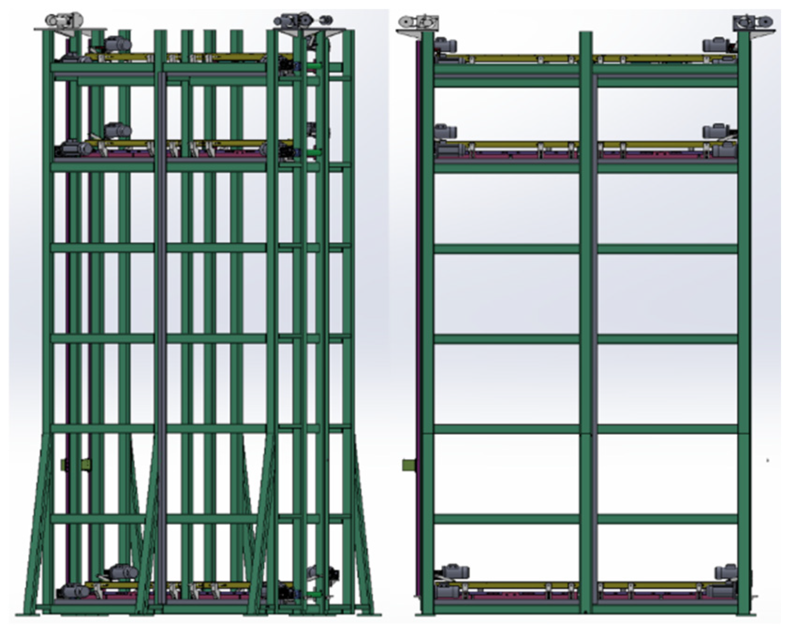
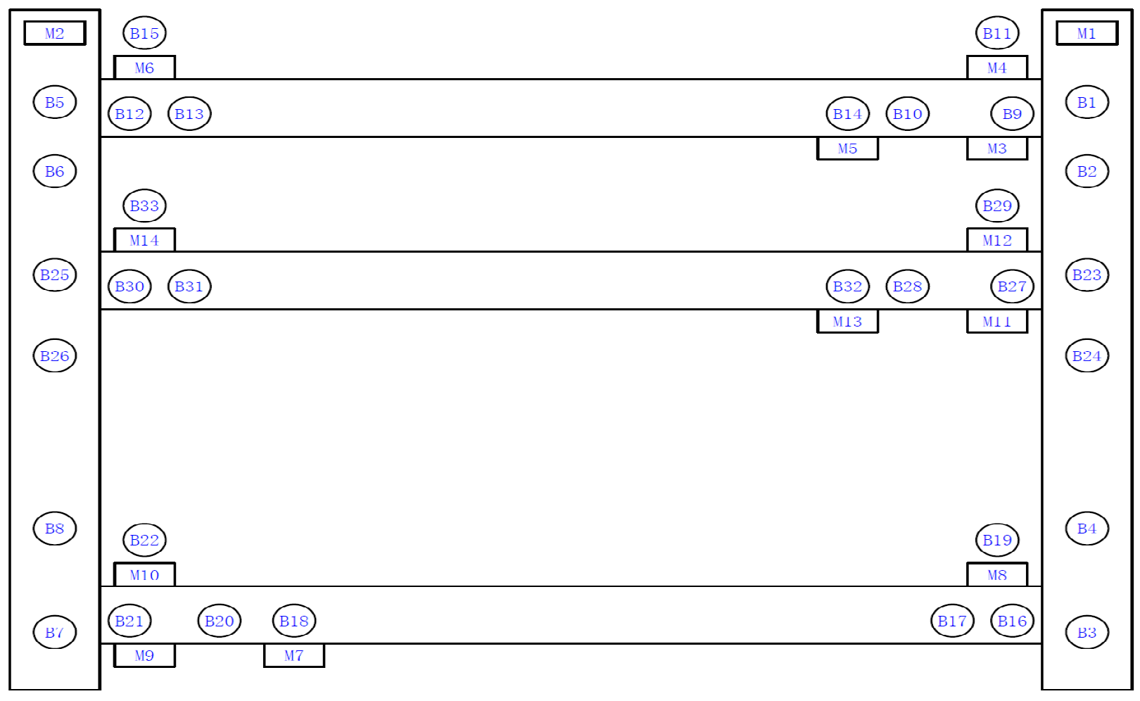
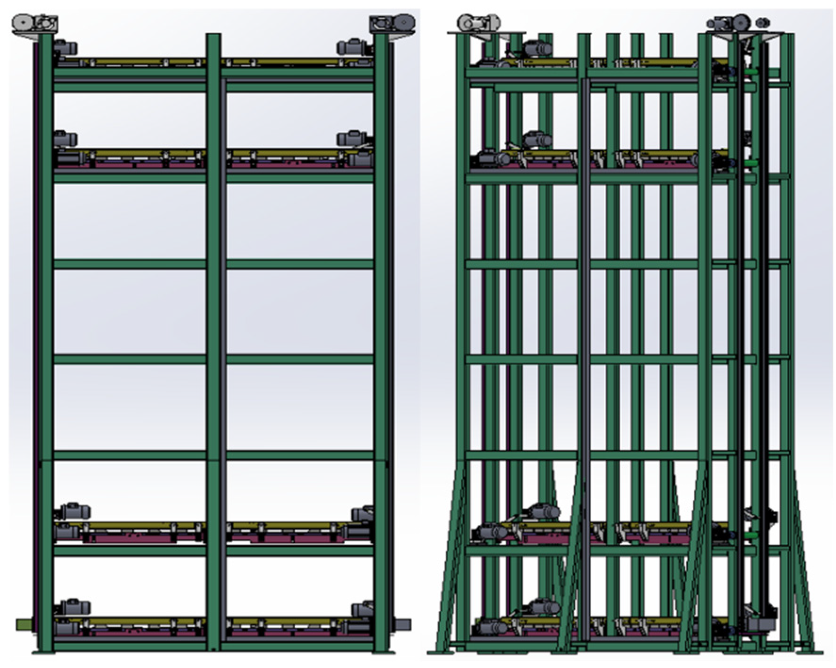
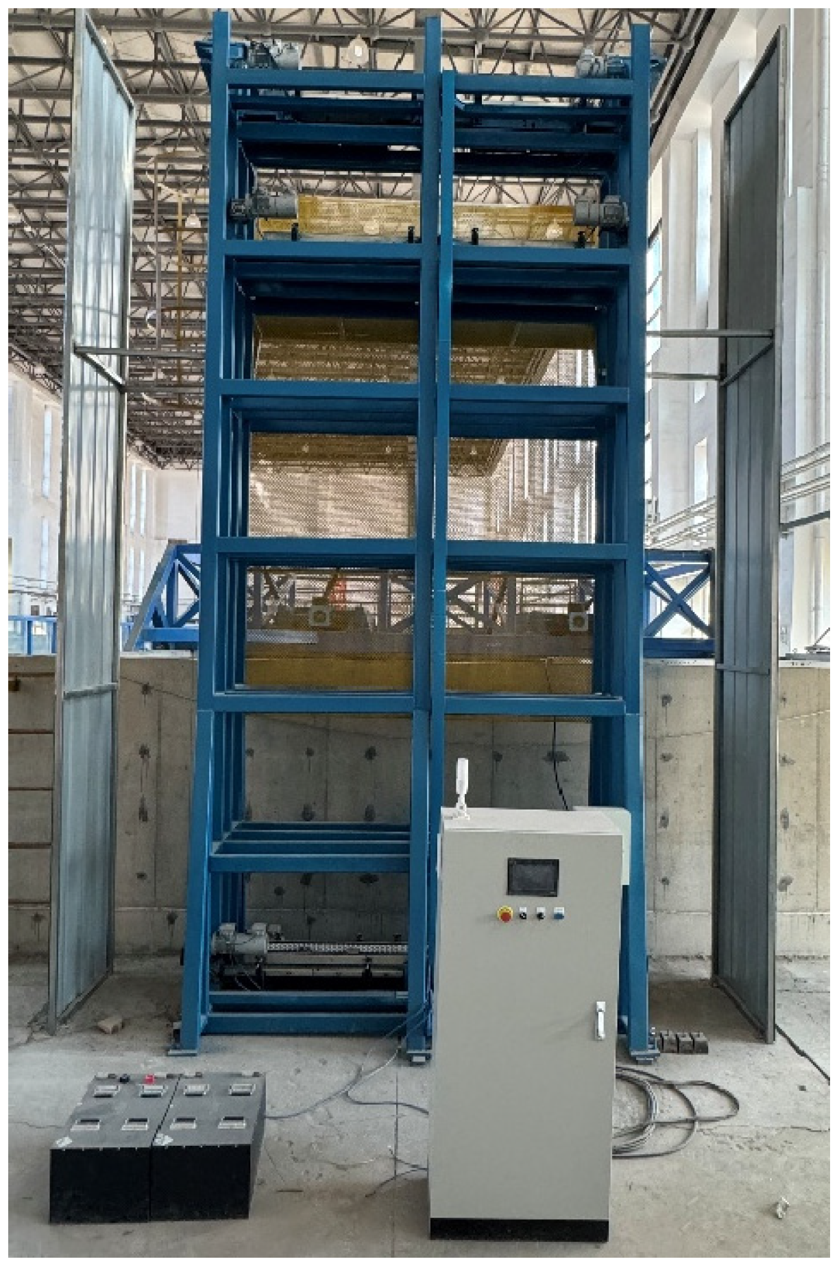
2.1. Overview of the Experimental Model Structure
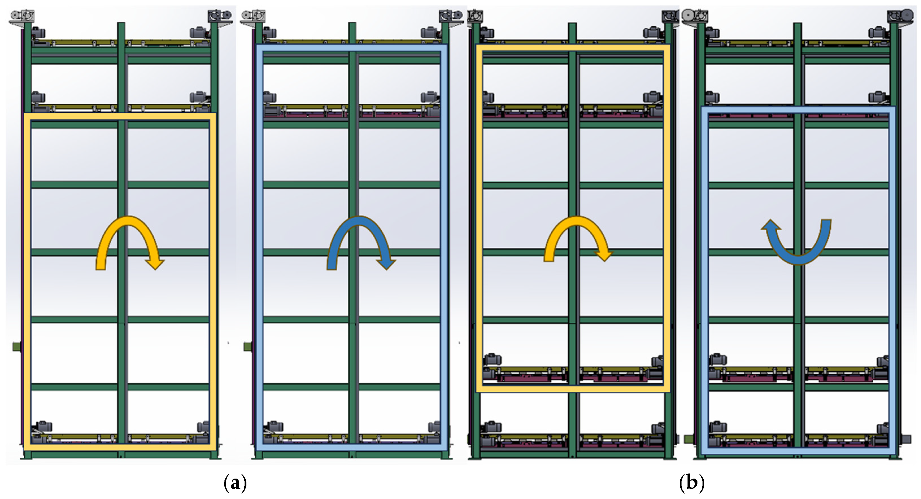
2.1.1. “Single Layer Double Height Difference” Structure
2.1.2. “Double Layer Single Height Difference” Structure
2.2. Main Theoretical Calculations
2.2.1. Energy Storage Calculation
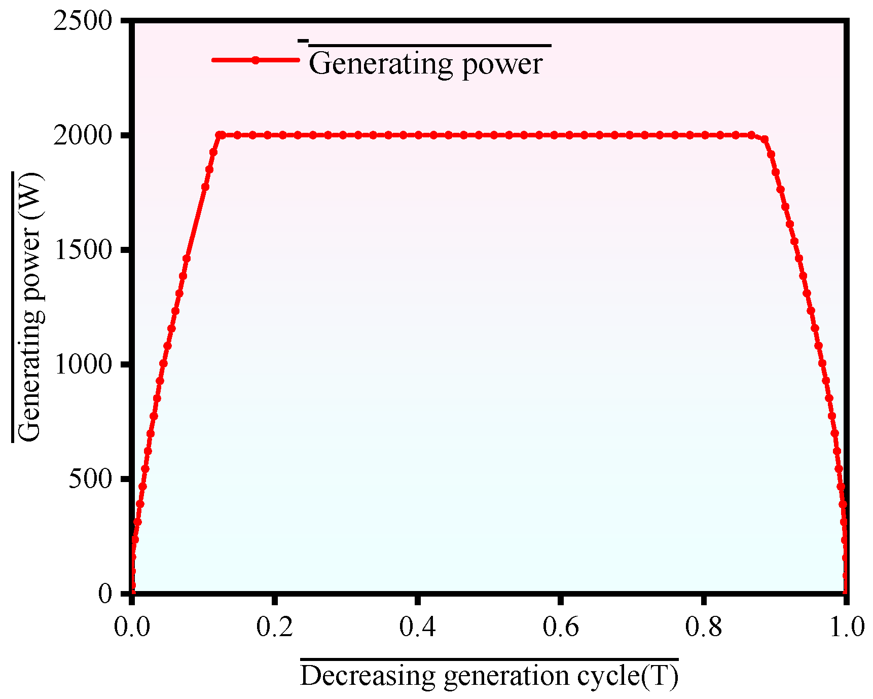
2.2.2. Power Generation Calculation
2.2.3. Energy Storage Efficiency
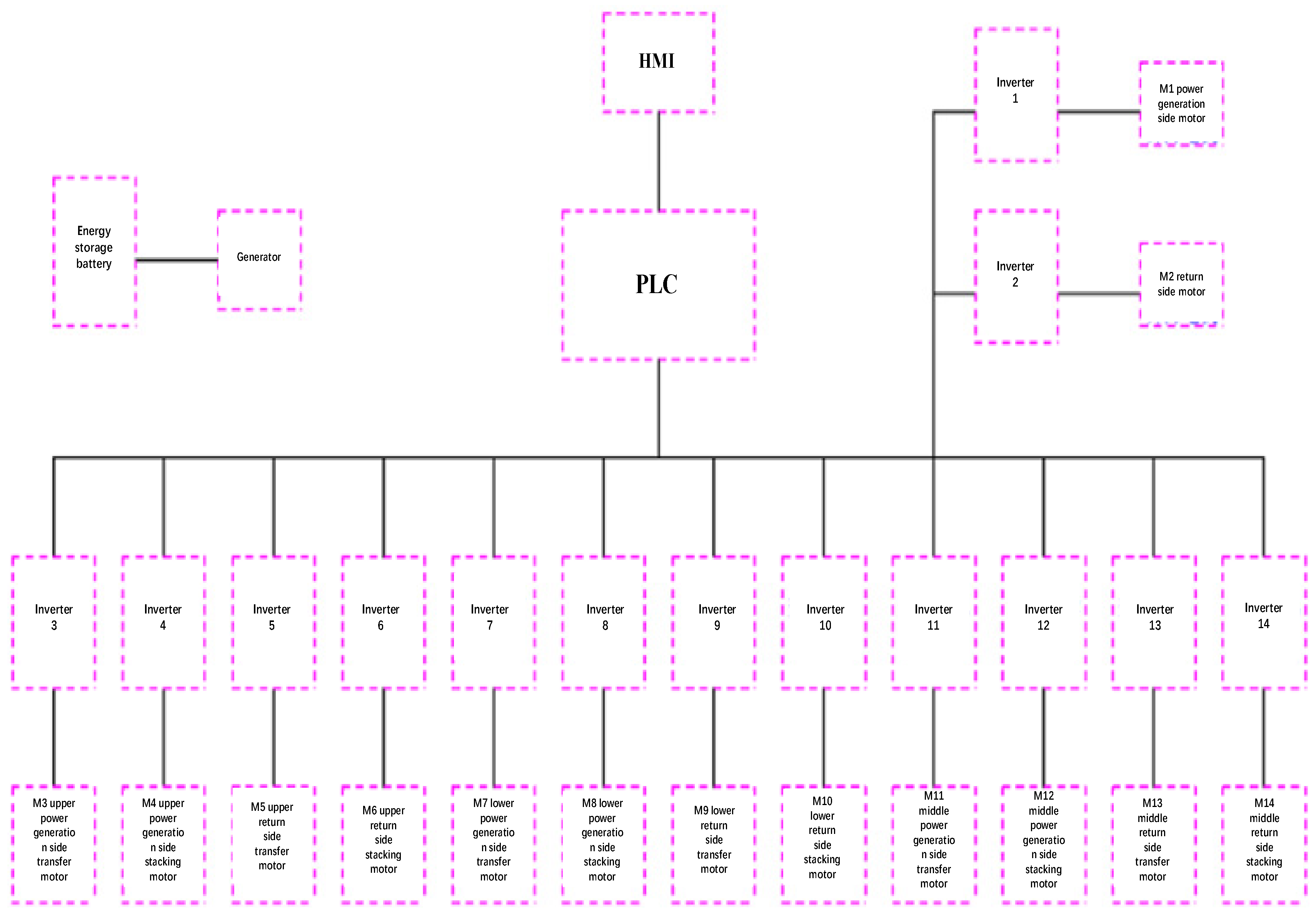
2.2.4. Generator Parameters
2.2.5. Energy Consumption Calculation
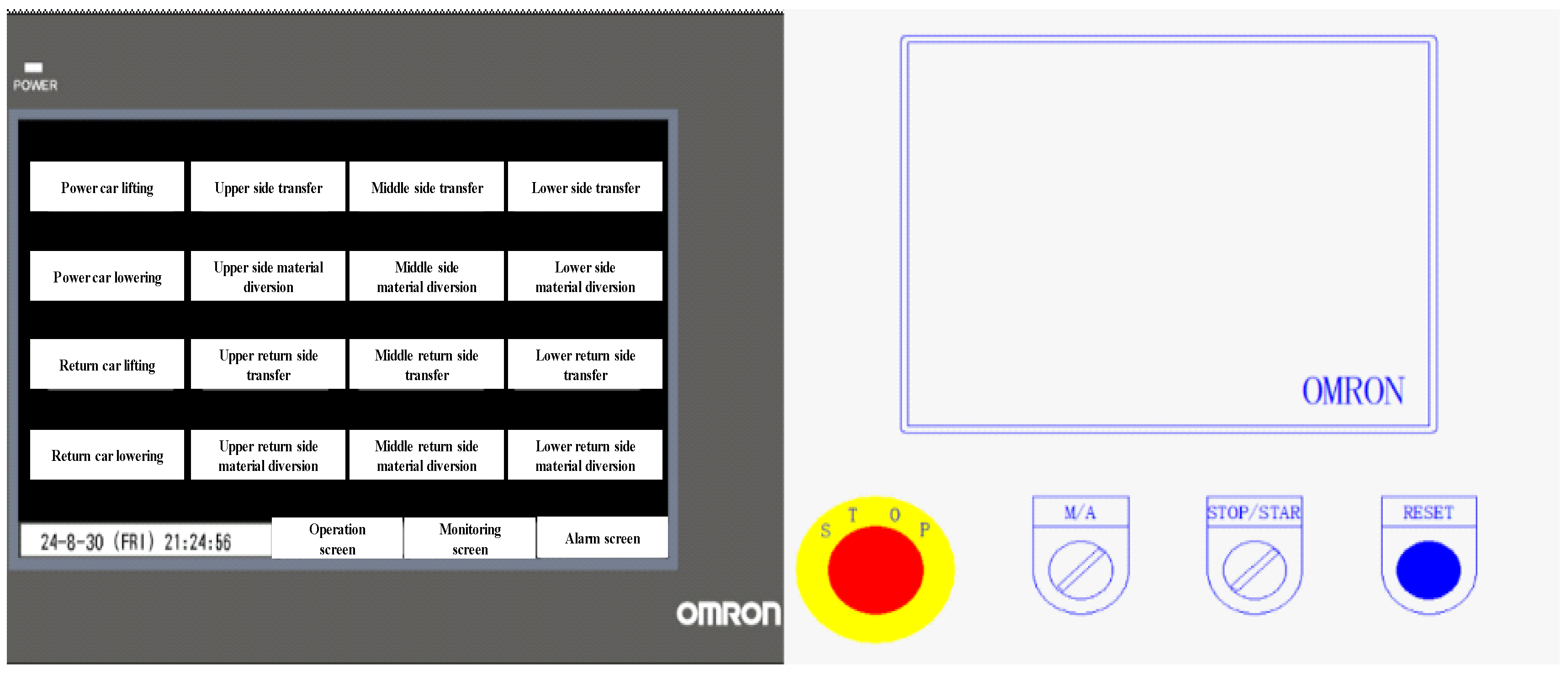
2.3. Experiment Method and Procedure
3. The Influence of the Weight of the Load and the Height of the Descent Section on Power Generation Efficiency
3.1. The Influence of Load Weight on Power Generation Efficiency
3.2. The Influence of the Acceleration Descent Height on Power Generation Efficiency at the Same Height
4. Conclusions
- a.
- The Synergistic Development of the Framework-Based Gravitational Energy Storage System and Zero-Carbon Ports: The application of the framework-based gravitational energy storage system not only meets the port’s need for a stable energy supply but also helps achieve a green and low-carbon transformation. By utilizing containers, an existing resource, the system efficiently stores and releases energy in space-limited environments such as ports, avoiding the large-scale consumption of new resources. This approach aligns with the principles of efficient resource utilization and green design. The system reduces dependence on traditional high-carbon energy sources while also minimizing the demand for new materials, thus lowering carbon emissions and resource waste.
- b.
- Optimization of Load Mass and Storage Height Promotes Sustainable Development: The experimental results in this paper indicate that load mass and storage height significantly affect the system’s power generation and storage efficiency. By reasonably selecting load mass and storage height, the energy storage efficiency can be improved, and the system’s stability and reliability during long-term operation can be ensured. This optimization design maximizes the utilization of limited resources by improving energy efficiency, reducing energy waste, and aligning with the goals of sustainable energy management.
- c.
- The Feasibility and Stability of the System Support Green Energy Applications: Through experimental schemes involving the “Double Layer Single Height Difference” and “Single Layer Double Height Difference” structures, this paper validates the performance of the framework-based gravitational energy storage system under different configurations, particularly highlighting the superior performance of the “Double Layer Single Height Difference” structure in reducing empty cabin motion. This design further enhances the system’s energy efficiency, ensures minimal energy loss during the storage process, and guarantees efficient energy utilization. It provides a practical solution for the green and sustainable energy supply for ports and surrounding areas.
- d.
- Advantages of the Framework-Based Gravitational Energy Storage System in Environmental Friendliness: The system effectively integrates with the existing infrastructure and equipment of ports, utilizing containers as a renewable resource and reducing the environmental cost of load procurement and manufacturing. This not only minimizes unnecessary resource consumption but also avoids pollution and emissions during the manufacturing process, making it an environmentally friendly energy storage technology. The implementation of the framework-based gravitational energy storage system reflects the principles of green design and circular economy, driving the development of environmentally friendly technologies in ports and other related industries.
Author Contributions
Funding
Institutional Review Board Statement
Informed Consent Statement
Data Availability Statement
Conflicts of Interest
Appendix A. Tables

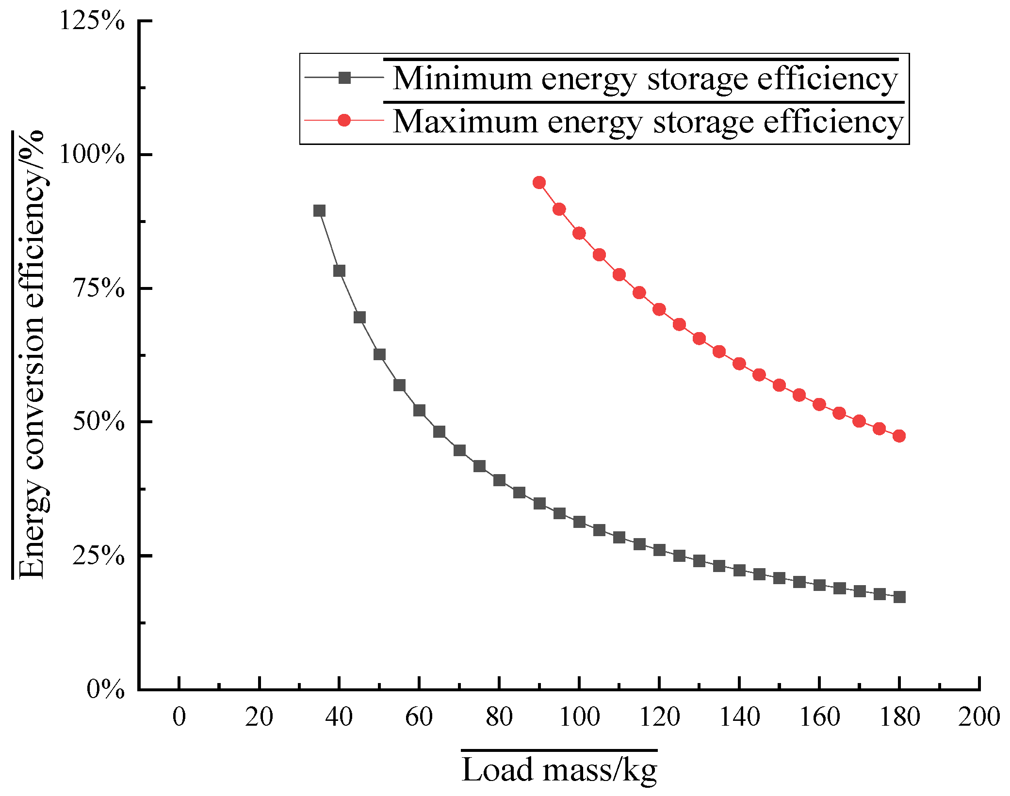
| t2 (s) | t3 (s) | M (kg) | WG (J) | Tmin (s) | Tmax (s) | WPmin (J) | WPmax (J) | ηmin | ηmax |
|---|---|---|---|---|---|---|---|---|---|
| 0.845 | 0.077 | 5 | 294.3 | 0.922 | 2.51 | 1844 | 5020 | - | - |
| 0.845 | 0.077 | 10 | 588.6 | 0.922 | 2.51 | 1844 | 5020 | - | - |
| 0.845 | 0.077 | 15 | 882.9 | 0.922 | 2.51 | 1844 | 5020 | - | - |
| 0.845 | 0.077 | 20 | 1177.2 | 0.922 | 2.51 | 1844 | 5020 | - | - |
| 0.845 | 0.077 | 25 | 1471.5 | 0.922 | 2.51 | 1844 | 5020 | - | - |
| 0.845 | 0.077 | 30 | 1765.8 | 0.922 | 2.51 | 1844 | 5020 | - | - |
| 0.845 | 0.077 | 35 | 2060.1 | 0.922 | 2.51 | 1844 | 5020 | 89.51% | - |
| 0.845 | 0.077 | 40 | 2354.4 | 0.922 | 2.51 | 1844 | 5020 | 78.32% | - |
| 0.845 | 0.077 | 45 | 2648.7 | 0.922 | 2.51 | 1844 | 5020 | 69.62% | - |
| 0.845 | 0.077 | 50 | 2943 | 0.922 | 2.51 | 1844 | 5020 | 62.66% | - |
| 0.845 | 0.077 | 55 | 3237.3 | 0.922 | 2.51 | 1844 | 5020 | 56.96% | - |
| 0.845 | 0.077 | 60 | 3531.6 | 0.922 | 2.51 | 1844 | 5020 | 52.21% | - |
| 0.845 | 0.077 | 65 | 3825.9 | 0.922 | 2.51 | 1844 | 5020 | 48.20% | - |
| 0.845 | 0.077 | 70 | 4120.2 | 0.922 | 2.51 | 1844 | 5020 | 44.76% | - |
| 0.845 | 0.077 | 75 | 4414.5 | 0.922 | 2.51 | 1844 | 5020 | 41.77% | - |
| 0.845 | 0.077 | 80 | 4708.8 | 0.922 | 2.51 | 1844 | 5020 | 39.16% | - |
| 0.845 | 0.077 | 85 | 5003.1 | 0.922 | 2.51 | 1844 | 5020 | 36.86% | - |
| 0.845 | 0.077 | 90 | 5297.4 | 0.922 | 2.51 | 1844 | 5020 | 34.81% | 94.76% |
| 0.845 | 0.077 | 95 | 5591.7 | 0.922 | 2.51 | 1844 | 5020 | 32.98% | 89.78% |
| 0.845 | 0.077 | 100 | 5886 | 0.922 | 2.51 | 1844 | 5020 | 31.33% | 85.29% |
| 0.845 | 0.077 | 105 | 6180.3 | 0.922 | 2.51 | 1844 | 5020 | 29.84% | 81.23% |
| 0.845 | 0.077 | 110 | 6474.6 | 0.922 | 2.51 | 1844 | 5020 | 28.48% | 77.53% |
| 0.845 | 0.077 | 115 | 6768.9 | 0.922 | 2.51 | 1844 | 5020 | 27.24% | 74.16% |
| 0.845 | 0.077 | 120 | 7063.2 | 0.922 | 2.51 | 1844 | 5020 | 26.11% | 71.07% |
| 0.845 | 0.077 | 125 | 7357.5 | 0.922 | 2.51 | 1844 | 5020 | 25.06% | 68.23% |
| 0.845 | 0.077 | 130 | 7651.8 | 0.922 | 2.51 | 1844 | 5020 | 24.10% | 65.61% |
| 0.845 | 0.077 | 135 | 7946.1 | 0.922 | 2.51 | 1844 | 5020 | 23.21% | 63.18% |
| 0.845 | 0.077 | 140 | 8240.4 | 0.922 | 2.51 | 1844 | 5020 | 22.38% | 60.92% |
| 0.845 | 0.077 | 145 | 8534.7 | 0.922 | 2.51 | 1844 | 5020 | 21.61% | 58.82% |
| 0.845 | 0.077 | 150 | 8829 | 0.922 | 2.51 | 1844 | 5020 | 20.89% | 56.86% |
| 0.845 | 0.077 | 155 | 9123.3 | 0.922 | 2.51 | 1844 | 5020 | 20.21% | 55.02% |
| 0.845 | 0.077 | 160 | 9417.6 | 0.922 | 2.51 | 1844 | 5020 | 19.58% | 53.30% |
| 0.845 | 0.077 | 165 | 9711.9 | 0.922 | 2.51 | 1844 | 5020 | 18.99% | 51.69% |
| 0.845 | 0.077 | 170 | 10,006.2 | 0.922 | 2.51 | 1844 | 5020 | 18.43% | 50.17% |
| 0.845 | 0.077 | 175 | 10,300.5 | 0.922 | 2.51 | 1844 | 5020 | 17.90% | 48.74% |
| 0.845 | 0.077 | 180 | 10,594.8 | 0.922 | 2.51 | 1844 | 5020 | 17.40% | 47.38% |
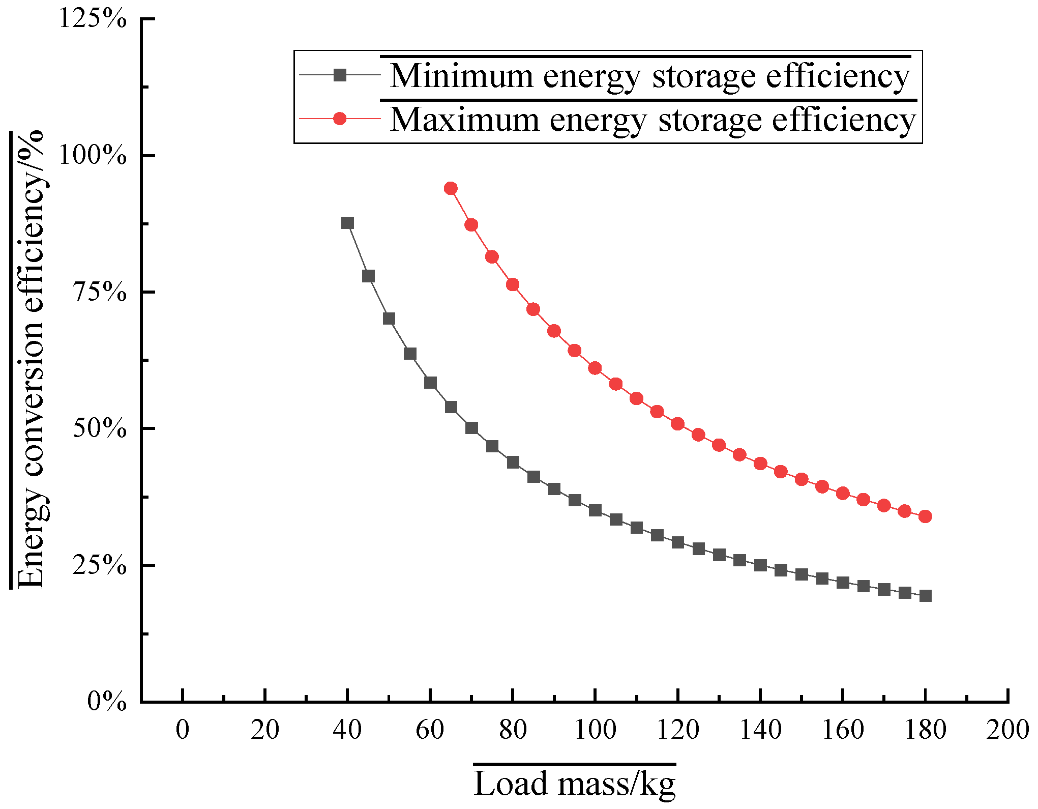
| t2 (s) | t3 (s) | M (kg) | WG (J) | Tmin (s) | Tmax (s) | WPmin (J) | WPmax (J) | ηmin | ηmax |
|---|---|---|---|---|---|---|---|---|---|
| 0.689 | 0.344 | 5 | 294.3 | 1.033 | 1.798 | 2066 | 3596 | - | - |
| 0.689 | 0.344 | 10 | 588.6 | 1.033 | 1.798 | 2066 | 3596 | - | - |
| 0.689 | 0.344 | 15 | 882.9 | 1.033 | 1.798 | 2066 | 3596 | - | - |
| 0.689 | 0.344 | 20 | 1177.2 | 1.033 | 1.798 | 2066 | 3596 | - | - |
| 0.689 | 0.344 | 25 | 1471.5 | 1.033 | 1.798 | 2066 | 3596 | - | - |
| 0.689 | 0.344 | 30 | 1765.8 | 1.033 | 1.798 | 2066 | 3596 | - | - |
| 0.689 | 0.344 | 35 | 2060.1 | 1.033 | 1.798 | 2066 | 3596 | - | - |
| 0.689 | 0.344 | 40 | 2354.4 | 1.033 | 1.798 | 2066 | 3596 | 87.75% | - |
| 0.689 | 0.344 | 45 | 2648.7 | 1.033 | 1.798 | 2066 | 3596 | 78.00% | - |
| 0.689 | 0.344 | 50 | 2943 | 1.033 | 1.798 | 2066 | 3596 | 70.20% | - |
| 0.689 | 0.344 | 55 | 3237.3 | 1.033 | 1.798 | 2066 | 3596 | 63.82% | - |
| 0.689 | 0.344 | 60 | 3531.6 | 1.033 | 1.798 | 2066 | 3596 | 58.50% | - |
| 0.689 | 0.344 | 65 | 3825.9 | 1.033 | 1.798 | 2066 | 3596 | 54.00% | 93.99% |
| 0.689 | 0.344 | 70 | 4120.2 | 1.033 | 1.798 | 2066 | 3596 | 50.14% | 87.28% |
| 0.689 | 0.344 | 75 | 4414.5 | 1.033 | 1.798 | 2066 | 3596 | 46.80% | 81.46% |
| 0.689 | 0.344 | 80 | 4708.8 | 1.033 | 1.798 | 2066 | 3596 | 43.88% | 76.37% |
| 0.689 | 0.344 | 85 | 5003.1 | 1.033 | 1.798 | 2066 | 3596 | 41.29% | 71.88% |
| 0.689 | 0.344 | 90 | 5297.4 | 1.033 | 1.798 | 2066 | 3596 | 39.00% | 67.88% |
| 0.689 | 0.344 | 95 | 5591.7 | 1.033 | 1.798 | 2066 | 3596 | 36.95% | 64.31% |
| 0.689 | 0.344 | 100 | 5886 | 1.033 | 1.798 | 2066 | 3596 | 35.10% | 61.09% |
| 0.689 | 0.344 | 105 | 6180.3 | 1.033 | 1.798 | 2066 | 3596 | 33.43% | 58.18% |
| 0.689 | 0.344 | 110 | 6474.6 | 1.033 | 1.798 | 2066 | 3596 | 31.91% | 55.54% |
| 0.689 | 0.344 | 115 | 6768.9 | 1.033 | 1.798 | 2066 | 3596 | 30.52% | 53.13% |
| 0.689 | 0.344 | 120 | 7063.2 | 1.033 | 1.798 | 2066 | 3596 | 29.25% | 50.91% |
| 0.689 | 0.344 | 125 | 7357.5 | 1.033 | 1.798 | 2066 | 3596 | 28.08% | 48.88% |
| 0.689 | 0.344 | 130 | 7651.8 | 1.033 | 1.798 | 2066 | 3596 | 27.00% | 47.00% |
| 0.689 | 0.344 | 135 | 7946.1 | 1.033 | 1.798 | 2066 | 3596 | 26.00% | 45.25% |
| 0.689 | 0.344 | 140 | 8240.4 | 1.033 | 1.798 | 2066 | 3596 | 25.07% | 43.64% |
| 0.689 | 0.344 | 145 | 8534.7 | 1.033 | 1.798 | 2066 | 3596 | 24.21% | 42.13% |
| 0.689 | 0.344 | 150 | 8829 | 1.033 | 1.798 | 2066 | 3596 | 23.40% | 40.73% |
| 0.689 | 0.344 | 155 | 9123.3 | 1.033 | 1.798 | 2066 | 3596 | 22.65% | 39.42% |
| 0.689 | 0.344 | 160 | 9417.6 | 1.033 | 1.798 | 2066 | 3596 | 21.94% | 38.18% |
| 0.689 | 0.344 | 165 | 9711.9 | 1.033 | 1.798 | 2066 | 3596 | 21.27% | 37.03% |
| 0.689 | 0.344 | 170 | 10,006.2 | 1.033 | 1.798 | 2066 | 3596 | 20.65% | 35.94% |
| 0.689 | 0.344 | 175 | 10,300.5 | 1.033 | 1.798 | 2066 | 3596 | 20.06% | 34.91% |
| 0.689 | 0.344 | 180 | 10,594.8 | 1.033 | 1.798 | 2066 | 3596 | 19.50% | 33.94% |
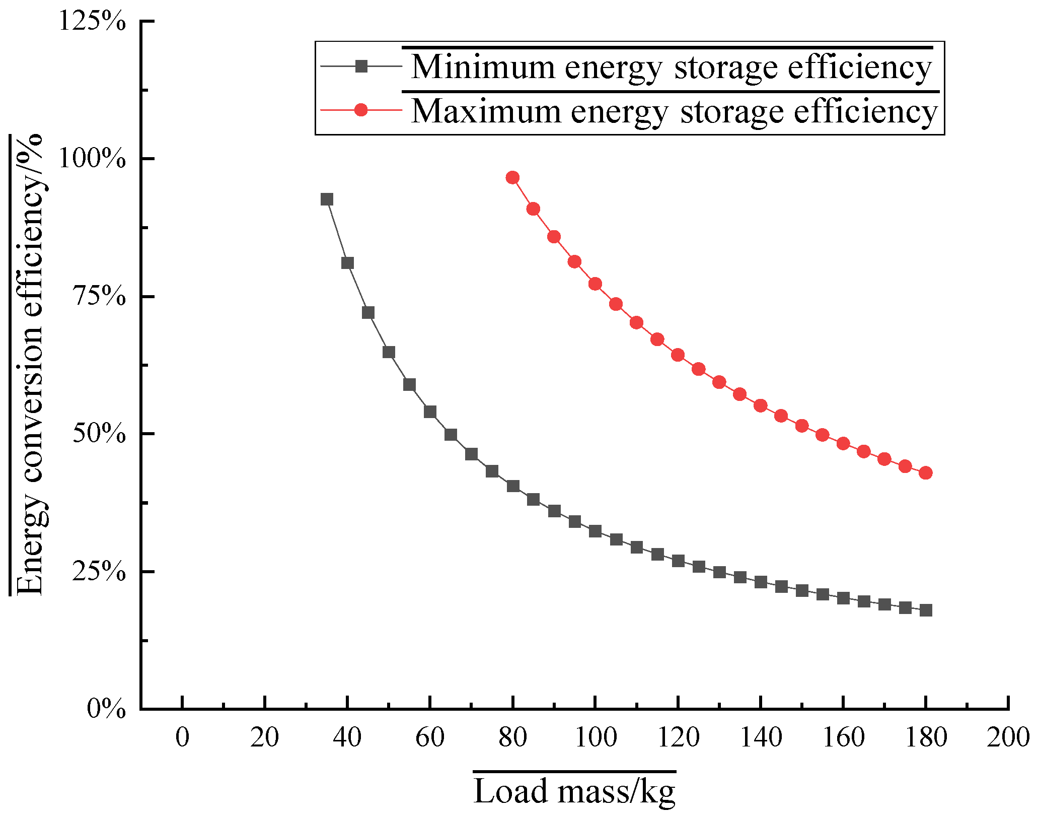
| t2 (s) | t3 (s) | M (kg) | WG (J) | Tmin (s) | Tmax (s) | WPmin (J) | WPmax (J) | ηmin | ηmax |
|---|---|---|---|---|---|---|---|---|---|
| 0.796 | 0.159 | 5 | 294.3 | 0.955 | 2.274 | 1910 | 4548 | - | - |
| 0.796 | 0.159 | 10 | 588.6 | 0.955 | 2.274 | 1910 | 4548 | - | - |
| 0.796 | 0.159 | 15 | 882.9 | 0.955 | 2.274 | 1910 | 4548 | - | - |
| 0.796 | 0.159 | 20 | 1177.2 | 0.955 | 2.274 | 1910 | 4548 | - | - |
| 0.796 | 0.159 | 25 | 1471.5 | 0.955 | 2.274 | 1910 | 4548 | - | - |
| 0.796 | 0.159 | 30 | 1765.8 | 0.955 | 2.274 | 1910 | 4548 | - | - |
| 0.796 | 0.159 | 35 | 2060.1 | 0.955 | 2.274 | 1910 | 4548 | 92.71% | - |
| 0.796 | 0.159 | 40 | 2354.4 | 0.955 | 2.274 | 1910 | 4548 | 81.12% | - |
| 0.796 | 0.159 | 45 | 2648.7 | 0.955 | 2.274 | 1910 | 4548 | 72.11% | - |
| 0.796 | 0.159 | 50 | 2943 | 0.955 | 2.274 | 1910 | 4548 | 64.90% | - |
| 0.796 | 0.159 | 55 | 3237.3 | 0.955 | 2.274 | 1910 | 4548 | 59.00% | - |
| 0.796 | 0.159 | 60 | 3531.6 | 0.955 | 2.274 | 1910 | 4548 | 54.08% | - |
| 0.796 | 0.159 | 65 | 3825.9 | 0.955 | 2.274 | 1910 | 4548 | 49.92% | - |
| 0.796 | 0.159 | 70 | 4120.2 | 0.955 | 2.274 | 1910 | 4548 | 46.36% | - |
| 0.796 | 0.159 | 75 | 4414.5 | 0.955 | 2.274 | 1910 | 4548 | 43.27% | - |
| 0.796 | 0.159 | 80 | 4708.8 | 0.955 | 2.274 | 1910 | 4548 | 40.56% | 96.59% |
| 0.796 | 0.159 | 85 | 5003.1 | 0.955 | 2.274 | 1910 | 4548 | 38.18% | 90.90% |
| 0.796 | 0.159 | 90 | 5297.4 | 0.955 | 2.274 | 1910 | 4548 | 36.06% | 85.85% |
| 0.796 | 0.159 | 95 | 5591.7 | 0.955 | 2.274 | 1910 | 4548 | 34.16% | 81.33% |
| 0.796 | 0.159 | 100 | 5886 | 0.955 | 2.274 | 1910 | 4548 | 32.45% | 77.27% |
| 0.796 | 0.159 | 105 | 6180.3 | 0.955 | 2.274 | 1910 | 4548 | 30.90% | 73.59% |
| 0.796 | 0.159 | 110 | 6474.6 | 0.955 | 2.274 | 1910 | 4548 | 29.50% | 70.24% |
| 0.796 | 0.159 | 115 | 6768.9 | 0.955 | 2.274 | 1910 | 4548 | 28.22% | 67.19% |
| 0.796 | 0.159 | 120 | 7063.2 | 0.955 | 2.274 | 1910 | 4548 | 27.04% | 64.39% |
| 0.796 | 0.159 | 125 | 7357.5 | 0.955 | 2.274 | 1910 | 4548 | 25.96% | 61.81% |
| 0.796 | 0.159 | 130 | 7651.8 | 0.955 | 2.274 | 1910 | 4548 | 24.96% | 59.44% |
| 0.796 | 0.159 | 135 | 7946.1 | 0.955 | 2.274 | 1910 | 4548 | 24.04% | 57.24% |
| 0.796 | 0.159 | 140 | 8240.4 | 0.955 | 2.274 | 1910 | 4548 | 23.18% | 55.19% |
| 0.796 | 0.159 | 145 | 8534.7 | 0.955 | 2.274 | 1910 | 4548 | 22.38% | 53.29% |
| 0.796 | 0.159 | 150 | 8829 | 0.955 | 2.274 | 1910 | 4548 | 21.63% | 51.51% |
| 0.796 | 0.159 | 155 | 9123.3 | 0.955 | 2.274 | 1910 | 4548 | 20.94% | 49.85% |
| 0.796 | 0.159 | 160 | 9417.6 | 0.955 | 2.274 | 1910 | 4548 | 20.28% | 48.29% |
| 0.796 | 0.159 | 165 | 9711.9 | 0.955 | 2.274 | 1910 | 4548 | 19.67% | 46.83% |
| 0.796 | 0.159 | 170 | 10,006.2 | 0.955 | 2.274 | 1910 | 4548 | 19.09% | 45.45% |
| 0.796 | 0.159 | 175 | 10,300.5 | 0.955 | 2.274 | 1910 | 4548 | 18.54% | 44.15% |
| 0.796 | 0.159 | 180 | 10,594.8 | 0.955 | 2.274 | 1910 | 4548 | 18.03% | 42.93% |
References
- Wang, Y.; Yang, X.; Chen, J.; Yang, D. The principle, efficiency, and material/site selection analysis of novel gravity energy storage. Eng. Res.-Interdiscip. Eng. Perspect. 2023, 15, 193–203. [Google Scholar]
- Shi, Q.; Wang, D.; Zeng, X.; Guo, Y.; Wang, H.; Xu, Z.; Deng, Q.; Zhong, H.; Wang, B.; Li, C. Research on the design of multi-rope friction hoisting system of vertical shaft gravity energy storage system. Appl. Sci. 2024, 14, 7556. [Google Scholar] [CrossRef]
- Liang, L. Discussion on the safety, stability, and power quality issues of new energy generation. Smart Build. Smart City 2024, 10, 97–99. [Google Scholar]
- Zhou, Y. Energy management and active power control method of new energy power stations with energy storage devices. Value Eng. 2024, 43, 107–109. [Google Scholar]
- Elsayed, M.E.; Abdo, S.; Attia, A.A.; Attia, E.A.; Abd Elrahman, M.A. Parametric optimisation for the design of gravity energy storage system using Taguchi method. Sci. Rep. 2022, 12, 19648. [Google Scholar] [CrossRef]
- Yu, H.; Yao, L.; Cheng, F.; Li, Y.; Zhai, W.; Wang, Q. Application of gravity energy storage in the new power system: Prospects and challenges. IEEE Trans. Electr. Eng. China 2024, 1–16. [Google Scholar] [CrossRef]
- Li, F.F.; Xie, J.Z.; Fan, Y.F.; Qiu, J. Potential of different forms of gravity energy storage. Sustain. Energy Technol. Assess. 2024, 64, 103728. [Google Scholar] [CrossRef]
- Botha, C.D.; Kamper, M.J. Design optimisation and cost analysis of linear vernier electric machine-based gravity energy storage systems. J. Energy Storage 2021, 44 Pt B, 103397. [Google Scholar] [CrossRef]
- Shi, Q.; Guo, R.; Hong, J.; Jiang, J.; Zeng, X.; Zhang, N.; Cao, J. Application and research of linear motors in vertical shaft gravity energy storage. South. Energy Constr. 2024, 11, 1–10. [Google Scholar]
- Shi, Q.; Wang, D.; Zeng, X.; Guo, Y.; Wang, H.; Xu, Z.; Deng, Q.; Zhong, H.; Wang, B.; Li, C. Factors affecting the power generation efficiency of vertical shaft gravity energy storage systems. South. Energy Constr. 2024, 14, 7556. [Google Scholar]
- Zhang, Z.; Chen, J.; Li, K.; Zhao, W. Analysis of work cycle scheduling strategy for hydraulic abandoned mine gravity energy storage systems. Mach. Tool Hydraul. 2024, 1–9. Available online: https://cfffgc1d129f57bb244a4huk0kq9woqx556wqxfgfy.eds.tju.edu.cn/kcms/detail/44.1259.th.20240719.1021.002.html (accessed on 1 March 2025).
- Qiu, Q.; Luo, X.; Lin, Y.; Wang, Q.; Li, Y.; Nie, Z.; Zhang, J.; Xiao, L. Research progress and key technologies of vertical gravity energy storage systems. Energy Storage Sci. Technol. 2024, 13, 934–945. [Google Scholar]
- Galetakis, M.; Biotakis, G.; Deligiorgis, V.; Varouchakis, E. Transforming decommissioned mines to a gravity energy storage system. Mater. Proc. 2023, 15, 14. [Google Scholar] [CrossRef]
- Yuan, Z.; Li, J.; Li, J.; Liu, B. A review of ground structure and inclined slope gravity energy storage systems. South. Energy Constr. 2024, 1–10. Available online: https://cfffgc1d129f57bb244a4huk0kq9woqx556wqxfgfy.eds.tju.edu.cn/kcms/detail/44.1715.TK.20240913.1617.002.html (accessed on 1 March 2025).
- Yang, C.; Hao, Z.; Chen, J. Research on grid connection control of inclined slope gravity energy storage systems. China Foreign Energy 2024, 29, 26–32. [Google Scholar]
- Yang, C. Study on Active Power Control of Inclined Slope Gravity Energy Storage Systems. Ph.D. Thesis, Guizhou University, Guizhou, China, 2024. [Google Scholar]
- Zhang, J.; Lin, Y.; Qiu, Q.; Xiao, L. Research progress on gravity energy storage technology based on slopes and mountains. Energy Storage Sci. Technol. 2024, 13, 924–933. [Google Scholar]
- Liu, D.; Mou, X.; Shi, B.; Chen, J.; Wang, B.; Luo, C.; Zhong, C.; Chen, S. Multi-software collaborative modeling method for mechanical and electrical co-simulation of inclined slope gravity energy storage systems. Energy Storage Sci. Technol. 2024, 13, 3266–3276. [Google Scholar]
- Gao, T.; Wang, Z.; Fang, S.; Zhang, Y.; Zhang, L.; Huang, Y.; Zhao, H. Energy efficiency analysis model and experimental validation of inclined slope gravity energy storage system with gear variable speed and chain drive mechanism. Energy Storage Sci. Technol. 2024, 14, 688–698. [Google Scholar]
- Yang, Q.; Liu, Q.; Fu, Q.; Yang, K.; Zhang, M.; Chen, Q. Smart microgrid construction in abandoned mines based on gravity energy storage. Heliyon 2023, 9, e21481. [Google Scholar] [CrossRef]
- Kropotin, P.; Marchuk, I. On efficiency of load-lifting rope-traction mechanisms used in gravity energy storage systems. J. Energy Storage 2023, 58, 106393. [Google Scholar] [CrossRef]
- Hu, L. Study on Control and Scheduling Optimization Methods of Efficient Gravity Energy Storage Systems. Ph.D. Thesis, Shandong University, Jinan, China, 2023. [Google Scholar]
- Wang, J.; Yang, Y.; Yang, Y.; Dong, Z. Simulation of control algorithm for matrix gravity energy storage system. China Sci. Technol. Inf. 2024, 10, 64–69. [Google Scholar]
- Xu, Z.; Li, J.; Zhang, C.; Hong, J. Net present value analysis of framework gravity energy storage per unit electricity. South. Energy Constr. 2024, 1–10. Available online: https://cfffgc1d129f57bb244a4huk0kq9woqx556wqxfgfy.eds.tju.edu.cn/kcms/detail/44.1715.TK.20240920.1523.002.html (accessed on 1 March 2025).
- Liu, X.; Yuan, K.; Bai, Y.; Wei, X. Economic analysis of framework gravity energy storage systems. Distrib. Energy 2023, 8, 47–53. [Google Scholar]
- Issa Zadeh, S.B.; Esteban Perez, M.D.; López-Gutiérrez, J.S.; Fernández-Sánchez, G. Optimizing smart energy infrastructure in smart ports: A systematic scoping review of carbon footprint reduction. J. Mar. Sci. Eng. 2023, 11, 1921. [Google Scholar] [CrossRef]
- Issa Zadeh, S.B.; López Gutiérrez, J.S.; Esteban, M.D.; Fernández-Sánchez, G.; Garay-Rondero, C.L. Scope of the literature on efforts to reduce the carbon footprint of seaports. Sustainability 2023, 15, 8558. [Google Scholar] [CrossRef]
- Du, M.; Huang, C.; Liao, L. Trade liberalization and energy efficiency: Quasi-natural experiment evidence from the pilot free trade zones in China. Econ. Anal. Policy 2025, 85, 1739–1751. [Google Scholar] [CrossRef]

Disclaimer/Publisher’s Note: The statements, opinions and data contained in all publications are solely those of the individual author(s) and contributor(s) and not of MDPI and/or the editor(s). MDPI and/or the editor(s) disclaim responsibility for any injury to people or property resulting from any ideas, methods, instructions or products referred to in the content. |
© 2025 by the authors. Licensee MDPI, Basel, Switzerland. This article is an open access article distributed under the terms and conditions of the Creative Commons Attribution (CC BY) license (https://creativecommons.org/licenses/by/4.0/).
Share and Cite
Lian, J.; Zhao, Y.; Jia, Z.; Qiu, Z.; Li, X. Research on the Power Generation Efficiency of Zero-Carbon Port Framework-Based Gravitational Energy Storage Systems. Sustainability 2025, 17, 3685. https://doi.org/10.3390/su17083685
Lian J, Zhao Y, Jia Z, Qiu Z, Li X. Research on the Power Generation Efficiency of Zero-Carbon Port Framework-Based Gravitational Energy Storage Systems. Sustainability. 2025; 17(8):3685. https://doi.org/10.3390/su17083685
Chicago/Turabian StyleLian, Jijian, Yingjiu Zhao, Zhaolin Jia, Zhaoguo Qiu, and Xinyi Li. 2025. "Research on the Power Generation Efficiency of Zero-Carbon Port Framework-Based Gravitational Energy Storage Systems" Sustainability 17, no. 8: 3685. https://doi.org/10.3390/su17083685
APA StyleLian, J., Zhao, Y., Jia, Z., Qiu, Z., & Li, X. (2025). Research on the Power Generation Efficiency of Zero-Carbon Port Framework-Based Gravitational Energy Storage Systems. Sustainability, 17(8), 3685. https://doi.org/10.3390/su17083685