Abstract
Traditionally, sea level is observed at tide gauge stations, which usually also serve as height reference stations for national leveling networks and therefore define a height system of a country. One of the main deficiencies to use tide gauge data for geodetic sea level research and height systems unification is that only a few stations are connected to the geometric network of a country by operating permanent GNSS receivers next to the tide gauge. As a new observation technique, absolute positioning by SAR using active transponders on ground can fill this gap by systematically observing time series of geometric heights at tide gauge stations. By additionally knowing the tide gauge geoid heights in a global height reference frame, one can finally obtain absolute sea level heights at each tide gauge. With this information the impact of climate change on the sea level can be quantified in an absolute manner and height systems can be connected across the oceans. First results from applying this technique at selected tide gauges at the Baltic coasts are promising but also exhibit some problems related to the new technique. The paper presents the concept of using the new observation type in an integrated sea level observing system and provides some early results for SAR positioning in the Baltic sea area.
1. Introduction
1.1. Height System Unification and Absolute Sea Level in a General Context
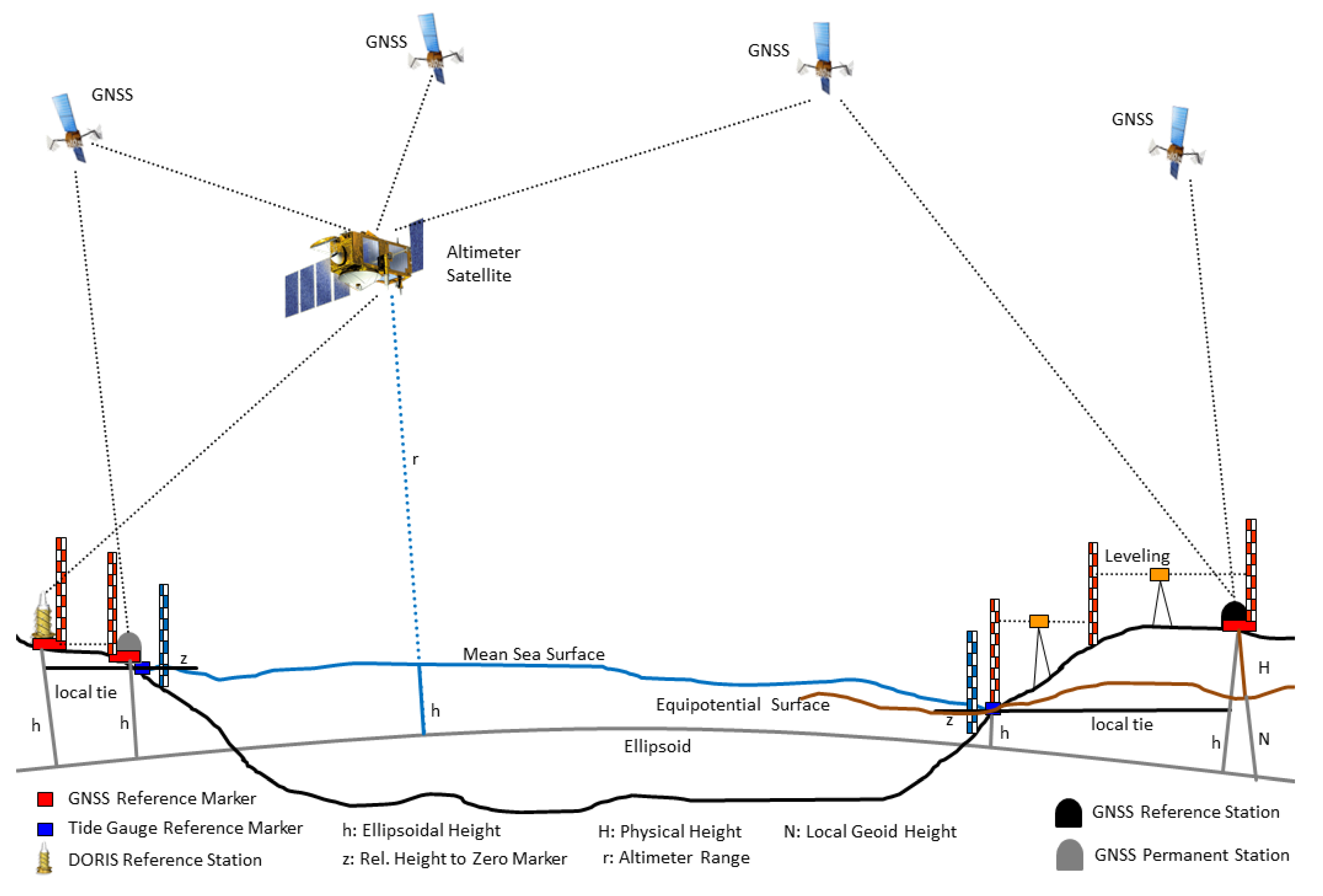
Sea level research nowadays is based on a number of measurement systems, which all have their own characteristics and deliver different types of observations [1,2]. Traditionally, sea level is observed at tide gauge stations, which usually also serve as height reference stations for national leveling networks and therefore define a height system of a country. Thus, sea level research across countries is closely linked to height system unification and needs to be regarded jointly. In order to analyze all observations, they need to be available in a common reference frame. Figure 1 shows an overview about the classical observation techniques and their connection to the reference systems.
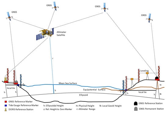
Figure 1.
Overview of classical observation systems for sea level research.
Over the open oceans, satellite altimetry is the main information source providing the absolute sea level at a specific location and at a specific time with respect to a geometric reference frame, which is implicitly defined by the orbit of the altimeter satellite and how this orbit is determined [3]. By analysis of these measurements in the space and time domain one can derive mean sea surfaces over specific areas and periods and/or the sea surface change in time, e.g., [4]. However, it is significantly less accurate close to the coastlines due to reflected signal distortions from land areas and due to less accurate geophysical corrections (e.g., ocean tides, wet tropospheric correction). Consequently, at least with current satellite systems, satellite altimetry is not capable of observing the absolute geometric sea surface height at coastal tide gauge stations with sufficient accuracy and therefore it cannot be used to connect tide gauge stations across oceans (countries) and to perform a height system unification.
At the coasts, sea level is usually observed with tide gauges delivering instantaneous sea surface heights relative to a zero marker of the tide gauge station [5,6]. Height changes, as observed at the tide gauges, at this point can be only regarded as relative changes of the sea surface with respect to the zero marker. For a long-term analysis and for the determination of absolute height changes with respect to a reference height, one needs to know if the zero marker of the station is stable or undergoes changes in height as well. Therefore, on-site observation of the relative motion of the zero marker with respect to a global geometric reference frame is required. This can be done by placing a GNSS receiver next to the tide gauge. The GNSS receiver monitors the vertical land motion (VLM) of the tide gauge station and by subtracting the vertical movement rate from sea level change rate observed with the tide gauge, one obtains the actual sea level change rate at this location [7,8].
If not only change rates but also absolute sea level heights shall be investigated and compared to each other, one needs to know the equipotential surface of the tide gauge zero marker and its physical height difference to the equipotential surface defining the height system of a country [9,10]. In case a height system of a country corresponds to one specific equipotential surface, one immediately can compare physical sea heights between tide gauge stations, by subtracting the physical heights of the tide gauge zero marker from the absolute ellipsoidal sea surface height, which is determined from the GNSS reference marker and the tide gauge observations, respectively. An important issue when subtracting physical from geometric heights is that both are available in consistent geometrical and physical reference frames, or in other words that any deviation between both needs to be taken into consideration.
In conclusion, only tide gauges can provide the sea level and its change directly at the coasts and therefore, they can be regarded as primary data source for technical and societal impact analysis of future sea level change and for unification of height systems. However, it also becomes obvious that for fully consistent and absolute sea level observations at the coasts, several quantities determined by different means need to be combined in a consistent reference system [11]. These quantities are the tide gauge observations relative to a zero marker, the ellipsoidal heights with respect to a geometric reference system, and the physical heights referring to a physical reference system.
1.2. Scientific Challenges
As pointed out, one of the critical issues is VLM, or more general vertical station movements [7,8,12,13]. For this purpose, optimally, a permanent geodetic accuracy GNSS receiver needs to be collocated next to the tide gauge station in order to observe such vertical movements. The number of tide gauge stations collocated with a permanent GNSS station is very limited and by far is not sufficient to monitor vertical station movements at the coast on a systematic basis. Alternatively, regular local surveys to the closest permanent GNSS stations by spirit leveling are needed. (cf. Figure 1). A significant effort would be needed to systematically observe the relative motion between the two sites in regular intervals over long periods by terrestrial measurements. Another alternative would be to model systematic VLM rates from geophysical models (e.g., for the glacial isostatic adjustment). These models exhibit large uncertainties and their results may differ significantly from results obtained with collocated GNSS observations [6].
Using tide gauge and collocated GNSS data is still not sufficient to enable comparisons of sea level from different stations in an absolute sense. This is only possible if one knows the vertical offsets of each tide gauge station from a global high resolution equipotential surface [10]. With the results of the GOCE mission a highly precise global geoid with centimeter accuracy and a spatial resolution of 80–100 km has become available [14,15]. This already provides a very good basis for defining a globally consistent equipotential surface, but one still needs to take care of the remaining omission error. Consequently, one needs to conduct a local geoid modeling for each tide gauge station with the global GOCE model as reference.
When combining tide gauge and GNSS based geometric heights with geoid based physical heights, one has to make sure that all observations are modeled in a common reference frame. This is an important issue as geometric and physical reference frames also have a time dependent component and need to be regarded in a joint approach.
In summary, three major scientific challenges need to be solved in order to enable height system unification or absolute sea level computation from tide gauge observations. These are:
- Connecting the tide gauge markers with the GNSS network geometrically in order to determine the relative vertical motion and to correct the tide gauge readings.
- Determine a GOCE based high resolution geoid height at tide gauge stations in order to deliver absolute heights of tide gauges with respect to a global equipotential surface as reference.
- Joint analysis of geometrical and physical reference frames to make them compatible and to determine corrections to be applied for combined analysis of geometric and physical heights.
1.3. Addressing the Scientific Challenges and Structure of the Paper
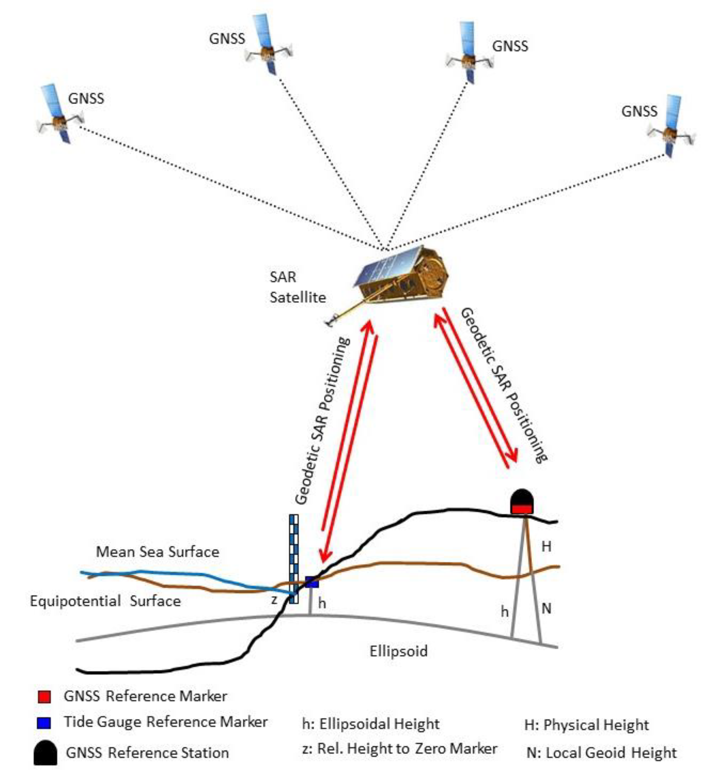
This work intends to address all three challenges, but the main focus is given to the connection of the tide gauge reference marker with the geometric GNSS network applying the geodetic SAR positioning technique [16]. With this technique tide gauges not permanently equipped with a GNSS receiver can be connected to the geometric network of a country with relatively little effort on a permanent basis (see Figure 2). With the X-Band TerraSAR-X and TanDEM-X SAR missions it was shown that 3D-positions can be determined with centimeter accuracy [17,18,19]. For C-band SAR similar analyses have been performed with corner reflectors [20] and by using active transponders as ground targets [21]. When combined with the flexibility of compact active transponders, it offers a relatively cheap and simple possibility to connect all tide gauges for an ocean area to the global geometric network. As a promising idea, a relative transfer of heights from nearby GNSS stations to the tide gauge station, if they both are observed in same SAR scene, can be considered (differential geodetic Stereo-SAR or SAR-leveling) [22]. A summary of the Geodetic SAR positioning technique including early results for the selected test cases is provided in Section 3.
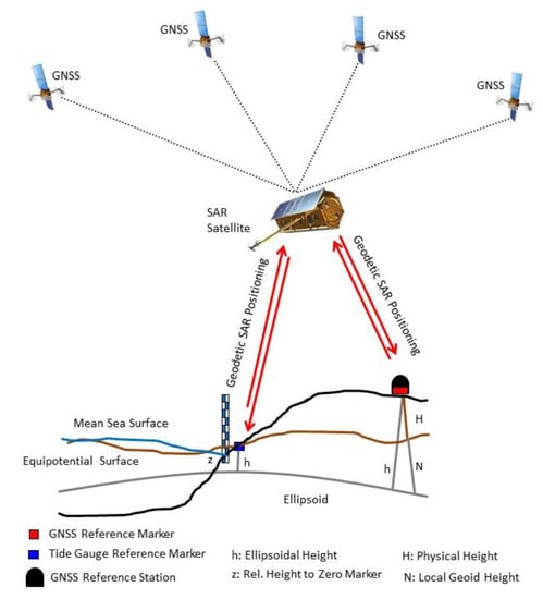
Figure 2.
Concept of Geodetic SAR for ellipsoidal height determination.
The available GOCE based satellite gravity field models and specifically the sixth release of these models, which are resulting from the GOCE reprocessing campaign, provide a global physical height reference surface (geoid) with centimeter accuracy down to roughly 80 km resolution [14,15]. Using these models as a global reference and combining them with local gravity information around the point of interest, the geoid can be determined with much higher spatial resolution consistently for all tide gauge stations. As the pure satellite gravity field model already covers spatial scales down to 80 km, it is sufficient to acquire gravity data in a circle of 100 kilometers around the station. The concept of local geoid modeling as it is applied in this study is introduced in Section 4.
For height system unification and absolute sea level analysis, a combination of geometric and physical heights needs to be done. Therefore, the applied geometric and physical reference systems need to be compatible. Offsets between both reference systems and their relative change in time need to be identified and applied as corrections. For example, by analyzing orbits of geodetic satellite missions and estimating positions and low degree gravity field coefficients simultaneously, such relative offsets can be determined [23]. The combination of ellipsoidal heights, geoid heights and tide gauge readings, and a more detailed analysis of the reference system issues are described in Section 5.
In order to investigate the feasibility of using active SAR transponders for geometric positioning and to use these observations for height system unification and absolute sea level determination, some tide gauge stations in the Baltic Sea area located in different countries were selected as test cases. The observation network and the setup of the experiments is described in detail in Section 2.
Finally, in Section 6 some preliminary conclusions from first data analyses are drawn and a plan for the remaining work to combine the different observation types is provided.
2. Test Case Baltic Sea
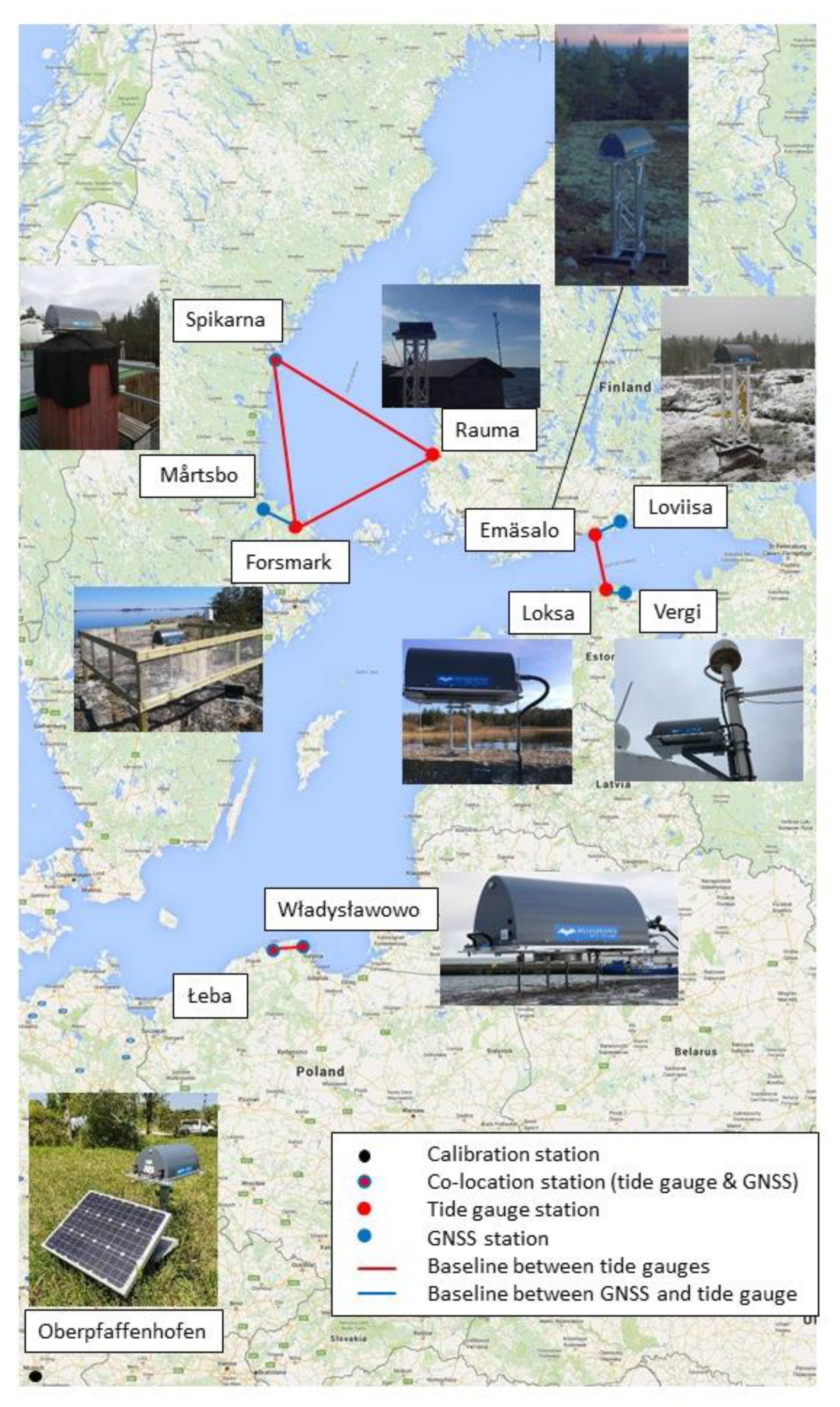
As a test case the Baltic Sea has been selected, because there exists a very good geodetic and marine infrastructure and there is a strong vertical land uplift (up to 1 cm per year height change). In 1990–1997, the international project Baltic Sea Level under auspices of IAG has been performed which enabled to connect 35 tide gauges with GPS stations [24,25]. So, the area is well suited to investigate the capabilities of the geodetic SAR technique for this purpose. A number of tide gauge stations in different countries have been identified, which are well suited to run the planned experiments. For the station selection, the following criteria were applied. The station needs to be easily accessible and a local tie of the SAR transponder to the tide gauge station shall be established. The SAR transponder shall have a free view to the Sentinel-1 satellites during flyby and no obstacles shall prevent observations from the satellites. In addition, radio frequency interference with other active instruments needs to be avoided. Apart from the tide gauge stations, also some permanent GNSS stations in the area of the selected tide gauge stations are identified and also equipped with active SAR transponders. For these the same selection criteria as described above are applicable. For the GNSS stations as an additional criterion it was defined that they shall be observable in the same SAR scene as the transponder at the related tide gauge station in order to enable relative observations. Finally, for calibration purposes, a well observed calibration site was selected, where next to the permanent GNSS station also conventional corner reflectors are available. The DLR station in Oberpfaffenhofen, Germany was selected in order to monitor the performance of the active transponders versus conventional corner reflectors. Even if this station is far away from the Baltic Sea, the calibration results can be applied to the transponders at the Baltic Sea as identical instruments are used. This led us to the station network shown in Figure 3. The figure also identifies potential experiments to link tide gauge and/or GNSS stations with others in order to transfer or compare heights between them. For the purpose of comparisons and calibration, in addition a network of selected GNSS stations has been separated and is being processed in a coherent and uniform manner. This includes selected GNSS stations near tide-gauge stations and IGS/EPN stations in the Baltic Sea region, acting as reference points.
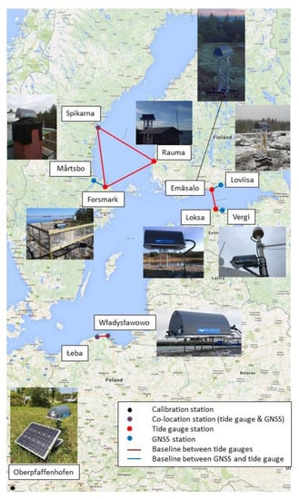
Figure 3.
Overview of selected tide gauge and GNSS stations equipped with SAR transponders and plan for station linking experiments.
Table 1 describes the stations, their link to other observables, and their operational status. Note that Table 1 lists the total number of scenes for ascending/descending arcs, but a station can be covered by up to five pass geometries and two satellites (Sentinel-1A and Sentinel-1B), depending on the acquisition plan [26]. For instance, Loksa comprises scenes from three ascending and two descending passes.

Table 1.
Overview of active transponder stations, their local tie, and status of operations. Note: The ECR in Spikarna/Vinberget was installed on 1st of October and has been operational since then. For the preliminary analyses only SAR scenes acquired until 7 August 2020 were used and therefore no results are shown for this station in Section 3.3.
All together 12 active transponders were purchased by the project team from MetaSensing BV and were installed on the stations as shown in Figure 3 and described in Table 1. These transponders often are called Electronic Corner Reflectors (ECR) in order to distinguish them from passive corner reflectors (CR), which can be used for the same purpose. For C-Band SAR very large CRs would be required (two meters in size) in order to receive sufficient signal responses. Therefore, for this application it is more convenient to use ECRs, which are much smaller in size (57 × 36 × 25 cm), optimized for C-band, and able to acquire observations for ascending and descending satellite orbits (in contrast to conventional CRs, which only can be used for either ascending or descending arcs) [27]. These ECRs work by receiving the signals from a passing satellite radar, amplifying this signal, and sending it back in the direction from which it came. In this way, it acts like a standard CR, but uses active technology, i.e., it is powered and it amplifies the radar signal electronically. It must keep time accurately in all weather conditions, meaning it has a GPS receiver inside to collect time data from the GPS network and maintain phase and time-delay stability across a wide range of temperatures. It needs its own power supply that can recharge itself for the duration of the activities, and these batteries must also work in all weather conditions. Furthermore, it must be able to communicate with the user, requiring a dedicated user interface (GUI) to allow the user to send satellite overpass times and check the status of the system. So far, such instruments are not yet operationally used. Therefore, within this project we have to collect experience in operations and performance of the ECRs and one needs to identify if they are suitable to be used for long term monitoring of a station.
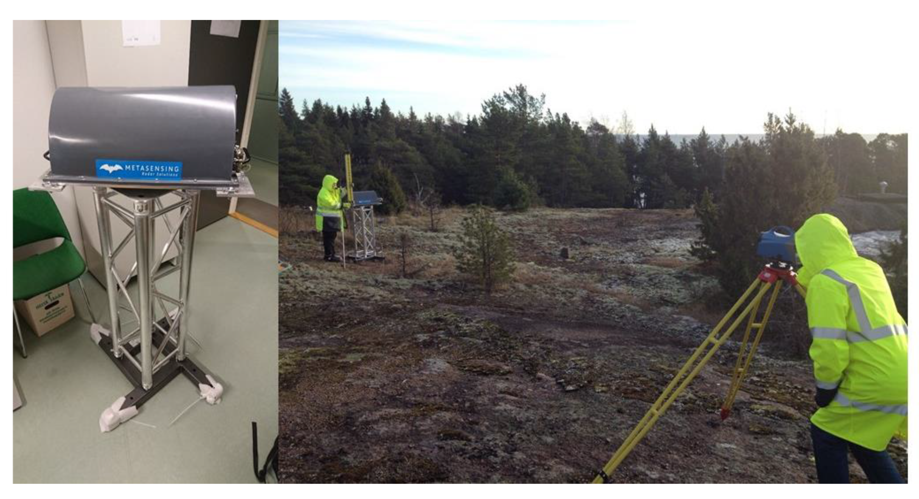
A very important aspect is the mounting of the system, the definition of the instruments phase center, and the relative offset of the phase center to the reference marker of the ECR. Further-on, when mounting the system, the offset of the ECR reference marker to the marker of the observation point needs to be determined. In order to link the ECR coordinate solutions to the tide gauge or GNSS reference marker, local surveys need to be done with high precision. These links are realized with standard geodetic measurement techniques. As an example, the mounting solution of the Finnish Geospatial Research Institute (FGI) and the local survey performed in Emäsalo, Finland is shown in Figure 4.
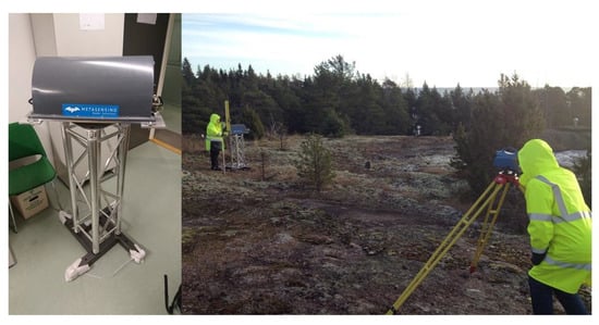
Figure 4.
ECR Mounting solution of FGI (left) and local survey of ECR in Emäsalo, Finland (courtesy FGI).
With the ECR transponders, which are installed at the stations indicated in Table 1, several experiments are planned, which are described in the following.
- Transponder Calibration: Two DLR owned transponders are installed at the DLR premises in Oberpfaffenhofen, Germany, as calibration stations. Both transponders are close to a permanent GNSS station and a standard trihedral CR with a dimension of 1.5 m. Additionally, SAR installations were surveyed by a local campaign with high precision GNSS receivers in order to enable an absolute comparison of positions. This calibration site specifically shall analyze the temporal stability of the ECR solutions and possible delay biases, which might be present in the ECR derived positions.
- Collocation Sites: These are locations where the ECR is directly tied to a tide gauge and a permanent GNSS station within some meters. These are the stations in Władysławowo, Łeba (both Poland) and Spikarna/Vinberget (Sweden). In addition, these sites can be used as second order calibration sites as they are directly tied to a permanent GNSS station as well.
- Tide Gauge Sites: The ECRs at the stations Emäsalo, Rauma, Loksa, and Forsmark are tied to local tide gauges. The resulting ECR positions are used to convert tide gauge heights to ellipsoidal heights and as such this experiment represents the standard case for the future assuming the performance of the absolute ECR positions is at centimeter level. The collocation sites can also be used for this experiment. One just needs to disregard the local tie to the GNSS station.
- Permanent GNSS Network Sites: The permanent GNSS stations Vergi, Loviisa, and Mårtsbo are equipped with an ECR, which is tied to the GNSS station but not linked with a tide gauge. These stations are intended to be used in order to perform an ellipsoidal height transfer from the GNSS station to the tide gauge station in a relative sense by doing differential ECR positioning (see Section 3). This short baseline experiment can be performed for linking Vergi to Loksa, Loviisa to Emäsalo, and Mårtsbo to Forsmark. In addition, the link between the collocation stations Władysławowo and Łeba can be used for this type of experiment.
- Long Baseline Experiment: Long baseline experiments crossing the Baltic Sea are planned by height transfer from Emäsalo to Loksa (North-South baseline) and for Spikarna/Vinberget and Forsmark/Kobben to Rauma (West-East baselines). These experiments shall link two tide gauges, which are connected via ECRs to permanent GNSS sites. The first experiment connects the tide gauges on both sides of the Gulf of Finland to a GNSS station, while the second is only tied on the Swedish side to the GNSS network.
- Tide Gauge Linking Experiment: Two nearby tide gauges are directly linked by means of ECR positions. For this experiment the Polish stations in Władysławowo and Łeba are used.
- Absolute versus Relative Coordinate Transfer: Coordinate transfer between two nearby SAR transponders is done either by absolute or by relative positioning technique (see Section 3). For this, a height transfer from ECR to ECR is done disregarding local ties to GNSS or tide gauge stations. The same baselines as identified for experiment 4 can be used for this analysis as well.
3. Geodetic SAR Data Analysis and Positioning Technique
In this section the technique for SAR data analysis and positioning are summarized. As all details are published in several papers (see References in the subsequent chapters), here only an overview with the most important processing steps will be provided.
3.1. SAR Data Analysis
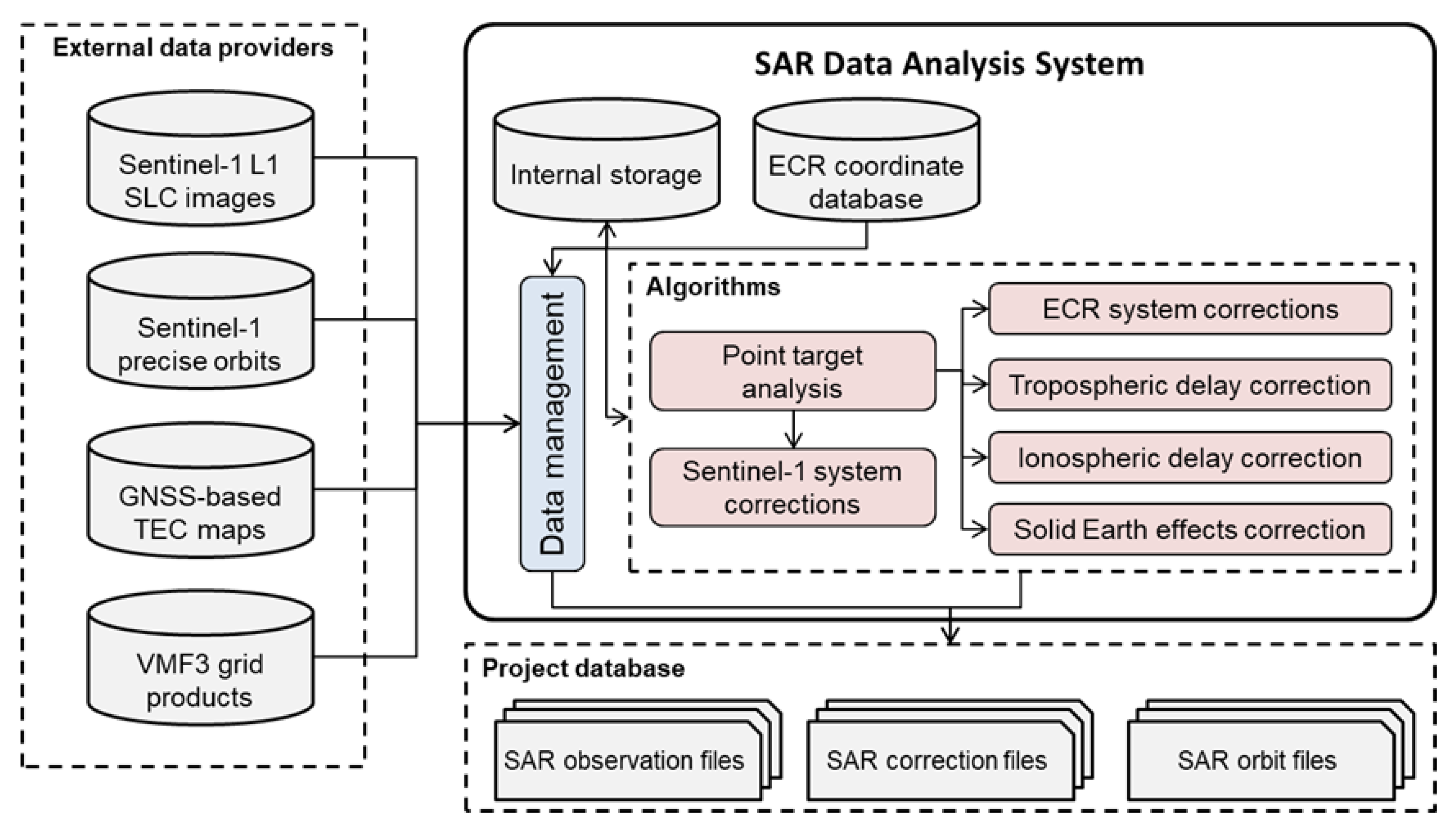
The SAR data analysis algorithms involve accurate extraction of all ECR locations from the acquired Sentinel-1 level 1 single-look complex (SLC) images as well as preparation of dedicated corrections. These corrections comprise the Sentinel-1 systematic effects not accounted for during SAR image generation, the atmospheric path delays, and the solid Earth deformation signals. Moreover, systematic effects of the ECRs need to be calibrated (internal signal delay, eccentricity of antennas). The applied computation methods require as data input the SLC Sentinel-1 SAR images, the Sentinel-1 precise orbit solution, the global total electron content (TEC) maps based on GNSS, and the global gridded data for the Vienna mapping function (VMF) model.
The overall processing scheme is outlined in Figure 5. The analysis system uses approximate coordinates of ECRs to download the applicable SAR image products. Orbit products matching the dates of the SAR images are obtained from the Sentinel-1 PDGS (Payload Data Ground Segment). The same procedure is applied to the atmospheric model data for which the files corresponding to the date of the SAR product are downloaded and ingested into the system.
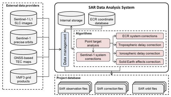
Figure 5.
SAR data analysis system. Data sets and output files are marked in grey. Red boxes refer to methods and algorithms.
3.1.1. SAR Image Point Target Analysis
The image point target analysis (PTA) extracts the ECR raw SAR timings range and azimuth from the Sentinel-1 level 1 SLC image products at subpixel level. A detailed description of PTA is provided in [28].
Single isolated point scatterers like the ECRs represent the impulse response of the SAR system. They appear as sinc-like functions that spread over several pixels in cross-shaped signatures and can be accurately localized in the image grid. The determination of signature locations in the SLC image is part of the PTA and yields subpixel positions. Assuming a given image resolution of 1 m and aiming at a SAR measurement accuracy on the order of 1 cm, then the PTA must provide the peak location with about 1/100 of a pixel. This is done by a moderate oversampling with spectral zero padding and by fitting an analytical paraboloid surface to the moderately oversampled central peak area [19,20]. The subpixel peak position is converted into radar timings by using the SAR image annotation, i.e., first sample azimuth time and range time as well as the range sampling frequency and the azimuth time interval.
3.1.2. Sentinel-1 Systematic Effects Correction
Corrections for Sentinel-1 systematic effects need to be applied to the raw azimuth and range timings. This includes corrections for the bistatic shifts in azimuth, for the Doppler shifts in range, and for the azimuth shifts due to the azimuth frequency modulation rate mismatch.
Bistatic effects in azimuth are caused by the movement of the platform between pulse transmission and echo reception. The movement of the Sentinel-1 satellites between pulse transmission and echo reception approximately amounts to 30-40 m. The Sentinel-1 Instrument Processing Facility (IPF) applies a simple shift (referred to as ‘‘bulk correction’’) to modify the azimuth timing annotation because of the assumptions used during the SAR image computation. This leads to subpixel distortions and range dependent shifts of 2–4 m in the azimuth measurements of Sentinel-1 Interferometric Wide-Swath (IW) products [20,29]. The postprocessing correction removes the original IPF bulk shift and applies the rigorous correction [20].
Doppler frequency shifts, which can reach up to ±0.4 m in range need to be removed applying the appropriate correction [20]. The transmitted radar pulses experience frequency shifts from the Doppler effect caused by the movement of the satellite.
The shifts caused by the mismatch of the azimuth Frequency Modulation (FM) rate used by the processer (assuming a constant scene height) and the true azimuth FM-rate for target position have to be corrected [20]. Shifts of up to 1 m were found at the edge of the burst if the assumed height in the computation of the azimuth FM-rate deviates about 1000 m.
3.1.3. Tropospheric and Ionospheric Delay Corrections
The tropospheric delay correction makes use of the Vienna Mapping Function (VMF3) model. The VMF3 is the latest development in a series of widely used mapping functions to convert tropospheric zenith path delays into slant path delays, which also provides tropospheric delays from numerical weather data integration allowing for observation correction [30]. The time-dependent VMF3 coefficients are computed from zenith path and slant range path integrations of the operational numerical weather model of the European Centre for Medium-Range Weather Forecast (ECMWF).
The tropospheric slant delay computation from the VMF3 product is defined in [30,31]. While interpolation resolves the temporal and horizontal dimensions, special care must be taken for the vertical dimension. The vertical integration of the ECMWF model is performed with respect to a global elevation model having a resolution of 1° by 1°. The height difference of the ECR with respect to this underlying elevation model has to be taken into account to derive proper slant path delays for the observed SAR ranges. The details of the height correction are given in [32].
The ionospheric delay correction is computed for the ECR location at date and time of the SAR acquisitions from Total Electron Content (TEC) maps. As in the case of SAR, the L-band carrier signals of GNSS are sensitive to the ionospheric delay, but simultaneous observations with two or more frequencies enables the GNSS to determine the ionospheric delay. This ability is exploited to generate global ionospheric maps from the GNSS observations of the global IGS network [33,34]. We use the product by the Center of Orbit Determination in Europe (CODE), because of the underlying methodology. Its computation is based on a consistent least squares inversion of daily GNSS observations that yields not only the vertical TEC (vTEC) maps but also the corresponding RMS information [33]. Typical TEC values of 20–30 TECU (TEC Units) (1 TECU = 1016 Electrons per m²) lead to 0.3–0.4 m when converted to delays in Sentinel-1 C-band. For details of the ionospheric delay computation see [20].
An additional point to be considered is the fact that the Sentinel-1 orbit lies still within the upper region of the ionosphere. Strictly speaking, resolving this would require the 3-D distribution of the free electrons and the integration of the electrons along the observed slant-range path. To our knowledge, there is not yet any global model which can provide such information with sufficient quality. Therefore, we decided for this empirical approach using a TEC scaling parameter to resolve this problem to some degree. An extrapolation based on the 75% scaling value found for TerraSAR-X ([35]) yields a scaling of 90% for Sentinel-1.
3.1.4. Solid Earth Effects Correction
The ITRF is realized through so-called regularized station coordinates representing the average state of the Earth’s crust [36]. Consequently, the observations of targets made by the SAR satellites, which refer to the dynamic state of the Earth’s surface at the time of observation, have to be corrected using the same procedures to obtain proper ITRF coordinates from the SAR.
The instantaneous positions of the ECRs during a SAR acquisition are modeled by the displacements computed from the conventional dynamic models at the date and time of SAR observation. These models encompass all the tidal related effects deforming the Earth’s crust (solid Earth, ocean, atmosphere) as well as secondary effects related to the dynamics of the Earth’s rotational axis. In total, these effects add up to displacements of approximately 0.3 m in the vertical direction and to approximately 0.06 m in the horizontal direction. The conventions of International Earth Rotation and Reference Systems Service (IERS) describe in detail all these models and sample programs are provided, which may be used to verify the calculations [36].
Conversion of displacements into corrections for the range and azimuth radar timings is performed by an iterative solution of the SAR Range-Doppler equations using the precise orbit data. The Doppler equation (see Section 3.2) is solved for the Zero-Doppler time for the given ECR position, as well as for the given ECR position including the displacement correction. The coarse ECR position as provided by the built-in GPS receiver is sufficient to perform the conversion. The range equation yields the range time by inserting the corresponding Zero-Doppler satellite position. The difference between both timing solutions yields the solid Earth deformation corrections for the SAR range and azimuth observations of the ECRs.
3.2. SAR Positioning
3.2.1. Absolute Positioning
The geometric relationship between the radar sensor and the radar target is mathematically expressed by the well-known Range-Doppler equations system (Equations (1) and (2)) [37]. For a given epoch, the equations relate the position vector X of the radar target with the sensor’s state vector (sensor position and sensor velocity) in a Cartesian reference frame. At this time instant, the geometry between the sensor and the target is expressed by the signal travel time to the target times the velocity of light c (the two-way travel time is considered) [19]. For radar images focused to Zero-Doppler geometry, the right hand-side of the second Doppler equations equals to zero [22].
- with:
- : position vector of radar target at epoch
- : position vector of sensor at epoch
- : velocity vector of sensor at epoch
- : speed of light
- : two-way signal travel time
The time τ corresponds to the two known radar range observation. As one can observe, the azimuth t is not directly included in the Range-Doppler equations. It is introduced via an analytical trajectory model, i.e., a polynomial orbit model of degree n, with coefficients a,b,c that can be estimated by least squares methods from the sensor trajectory state vectors, which are usually provided by the orbit determination of the SAR satellite (Equation (3)) [19,22]. Polynomials of degree six are typically used.
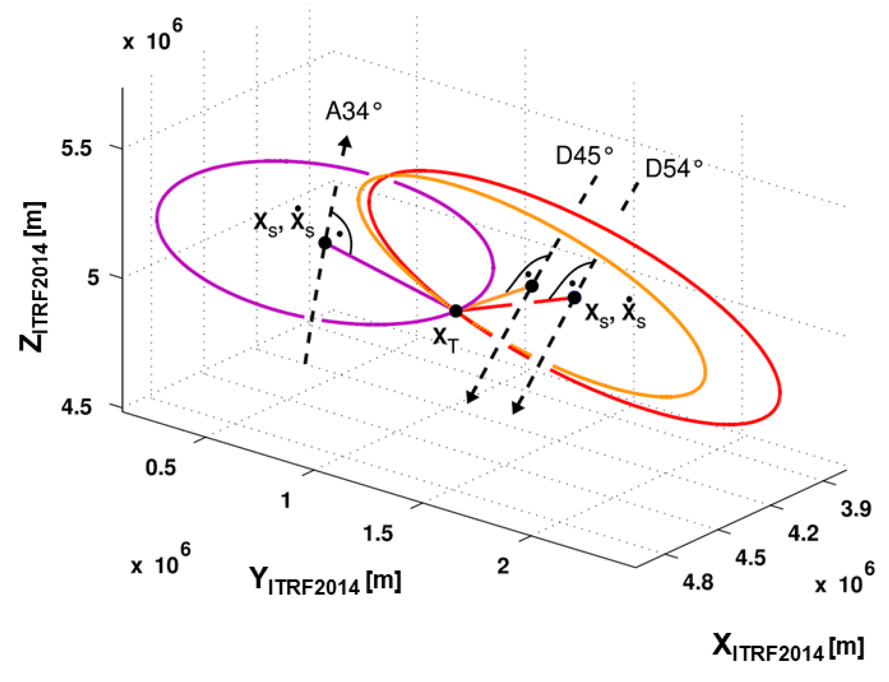
If the above Equation (3) is introduced into the Zero-Doppler Equations (1) and (2), the 3D location of a target with t and τ is reduced to a circle perpendicularly oriented to the satellite’s flight direction [19]. Figure 6 depicts three image acquisitions, one from an ascending and two from a descending satellite pass, all containing the same target. It is evident that in order to solve for the position vector, at least two acquisitions are required, most preferably acquired from different geometries.
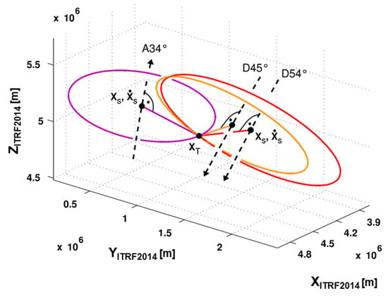
Figure 6.
Graphical representation of the Range-Doppler equation system in Zero-Doppler mode (each color represents a single coordinate solution from one image) [22].
Mathematically, the equation system can be fully linearized and solved according to the concept of adjustment of conditions with additional parameters (Equation (4)) [38].
Matrix B holds the conditions for the observations t and τ, l is the observation vector, A is the design matrix for the three unknown target coordinates, and x is the unknown parameters vector. Vector v contains the observations residuals and w = Bl-b accounts for inconsistencies of the system demanding the outcome b, which is resolved by x and v [19,22]. B and A are generated by differentiating the Range-Doppler equations including the polynomial orbit model as described in [19]. The observation residuals are minimized by the adjustment, stating the L2 norm: vTPv is minimized. The weight matrix P is defined as the inverse of the observation variance-covariance matrix. The adjustment is performed iteratively, starting from an initial guess for the target location. As the solution converges, the inconsistencies eventually decay, while the residuals v are minimized. Since the image acquisitions are independent from each other, the matrix B has a quadratic block diagonal structure that allows its inversion. Therefore, if we denote and the above equations can be converted to a Gauss–Markov model, which can be solved by Equation (5) [38].
The vector denotes the estimates of the unknown parameters, while is the 3 × 3 variance-covariance matrix which provides the standard deviations of the target coordinates and which can be converted to the corresponding error ellipsoid. The weighting of the different observation types within the parameters estimation is done via variance component estimation (VCE), which yields additionally estimated range and azimuth standard deviations. Details about the quality indicators and the variance component estimation can be found in [19].
3.2.2. Relative Positioning
Similar to the principle of differential GNSS, a target with known a priori coordinates can be used to solve for the coordinates of additional targets. In the differential geodetic SAR setup, the velocity of the reference target within the ITRF needs to be additionally considered, since the reference coordinates must be established for the individual epochs of the SAR observations [22]. For a reference target at an epoch of an acquisition (derived from the Range-Doppler equation), the range and azimuth observations of k targets can be considered differentially with respect to the observations of the reference target [22]:
The coordinates to be solved can be expressed as coordinate differences:
The Range-Doppler equation system for the Zero-Doppler case (Equations (1) and (2)), then takes the form:
with the polynomial orbit model (Equation (3)) being extended as:
The solution of the differential case follows the procedure described in Section 3.2.1, with B and A computed from the equations above, and as input observations, and as the unknown to be resolved. For the relative setup at a local site, spatial correlation of the external disturbances can be assumed, therefore eliminating the need of applying corrections to the range and azimuth observations of the targets. There is however an increase of the random SAR observation error due to the data combination, with an estimated growth by approximately a factor of 2. More details on the relative extension of the SAR positioning can be found in [22].
3.2.3. Data Processing Chain
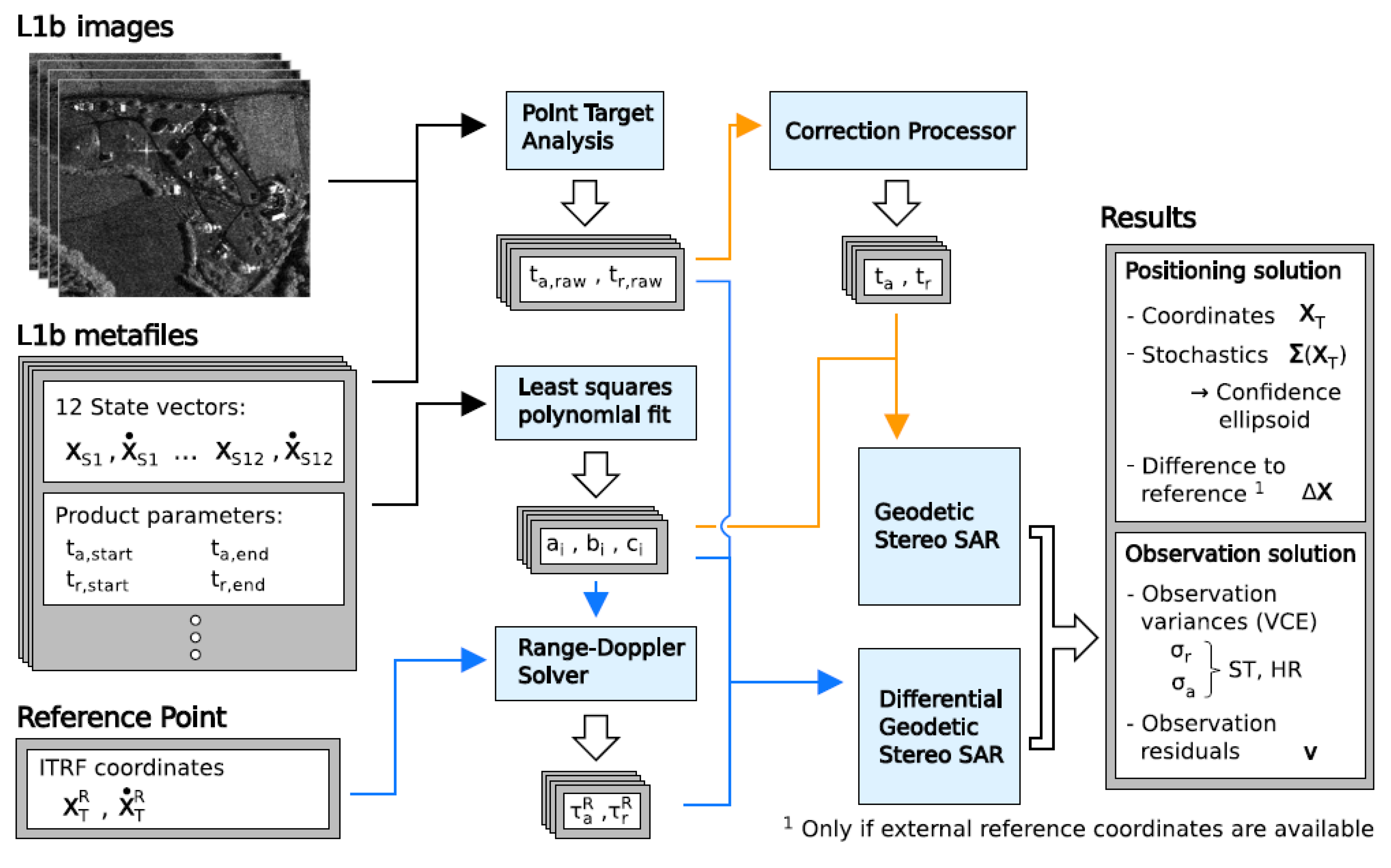
The procedures described for the standard (Section 3.2.1) and the relative (Section 3.2.2) geodetic SAR, are applied by the “3D Stereo SAR” module of a SAR processor software developed in MATLAB. The processing scheme for both the standard and the relative approaches for geodetic SAR positioning follows the SAR data analysis (Section 3.1 and Figure 5). It is described in Figure 7 and in the subsequent paragraphs.
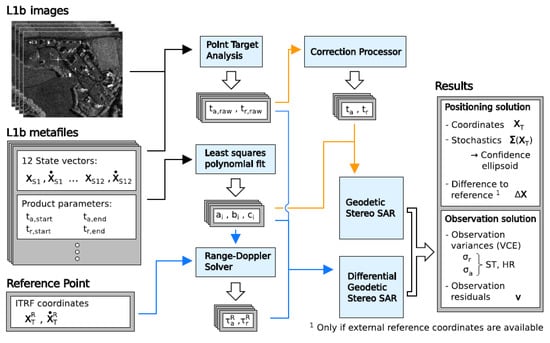
Figure 7.
Processing scheme of geodetic stereo SAR for the standard (orange arrows) and the differential approach (blue arrows) [22].
Absolute Geodetic SAR—Processing steps
- Azimuth and range are extracted at subpixel level from the Zero-Doppler SLC Sentinel-1 images using Point Target Analysis (PTA) (see Section 3.1).
- The raw timings are corrected for the geodynamic and atmospheric effects and SAR systematic effects.
- The polynomial orbit model’s coefficients are estimated by means of least squares fit.The Geodetic SAR algorithm as described in Section 3.2.1 is applied.
Relative Geodetic SAR—Processing steps
- Azimuth and range are extracted at subpixel level from the Zero-Doppler SLC Sentinel-1 images using Point Target Analysis (PTA) (see Section 3.1).
- The polynomial orbit model’s coefficients are estimated by means of least squares fit.
- The azimuth and range of the reference target are derived from the Range-Doppler equations.The Geodetic SAR algorithm as described in Section 3.2.2 is applied.
The Geodetic SAR processor solves for the unknown X, Y, Z target coordinates, which has been observed from at least two different acquisitions. For a reliable solution, acquisitions from both ascending and descending passes, as well as acquisitions from different adjacent tracks, should be considered. The results of the parameter estimation include the X, Y, Z target coordinates in the ITRF2014, the uncertainties of the target coordinates (variances and covariances), the range and azimuth standard deviations provided by variance component estimation, and the observation residuals.
3.3. First Results and Discussion
The absolute coordinates of all the ECRs installed at the Baltic stations and at DLR have been estimated using the 3D SAR processor (Section 3.1) and the SAR positioning (Section 3.2). For the processing we use all available observations since the start-of-operations of the respective ECR station and till 30 July 2020. In the following, the absolute positioning results are described for the 11 stations equipped with ECRs. The station located in Emäsalo, Finland, is given as an example to show the effects of refining the process of absolute positioning.
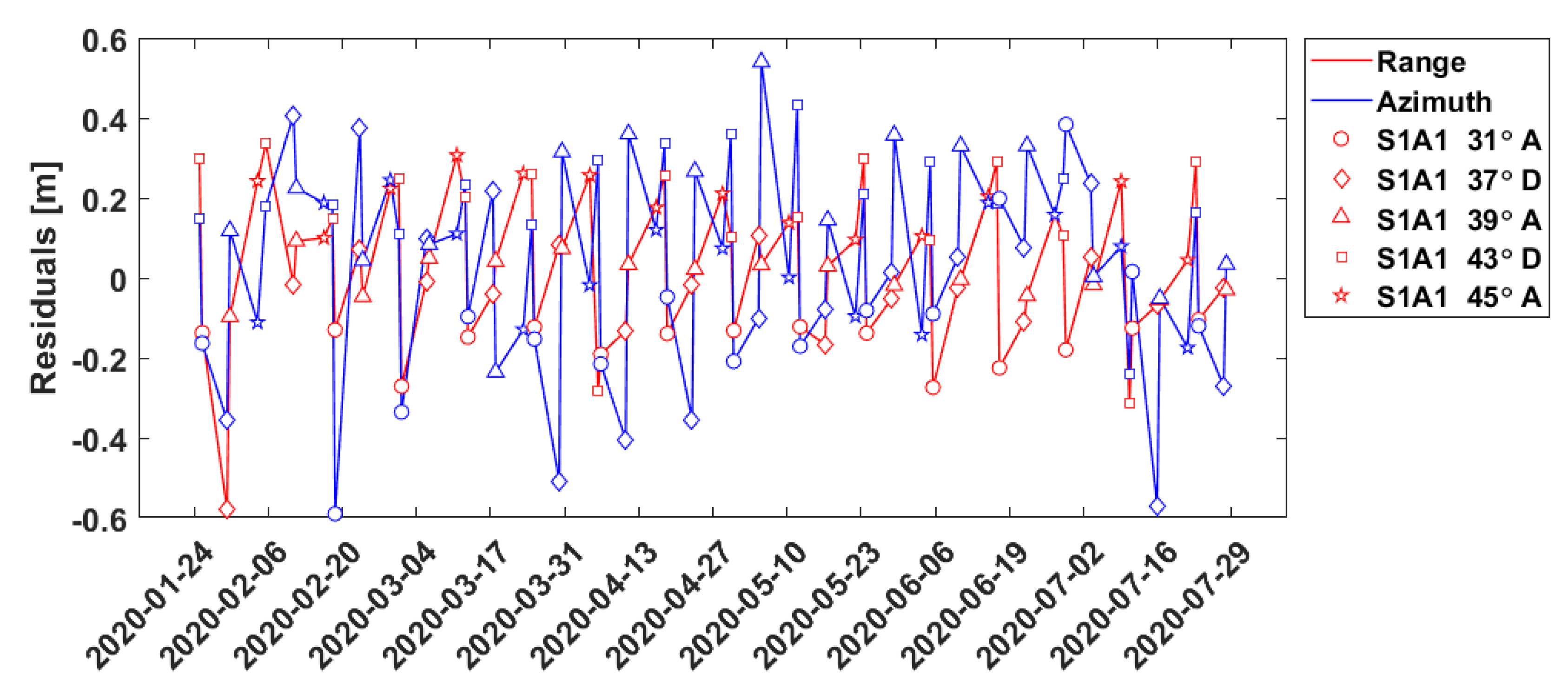
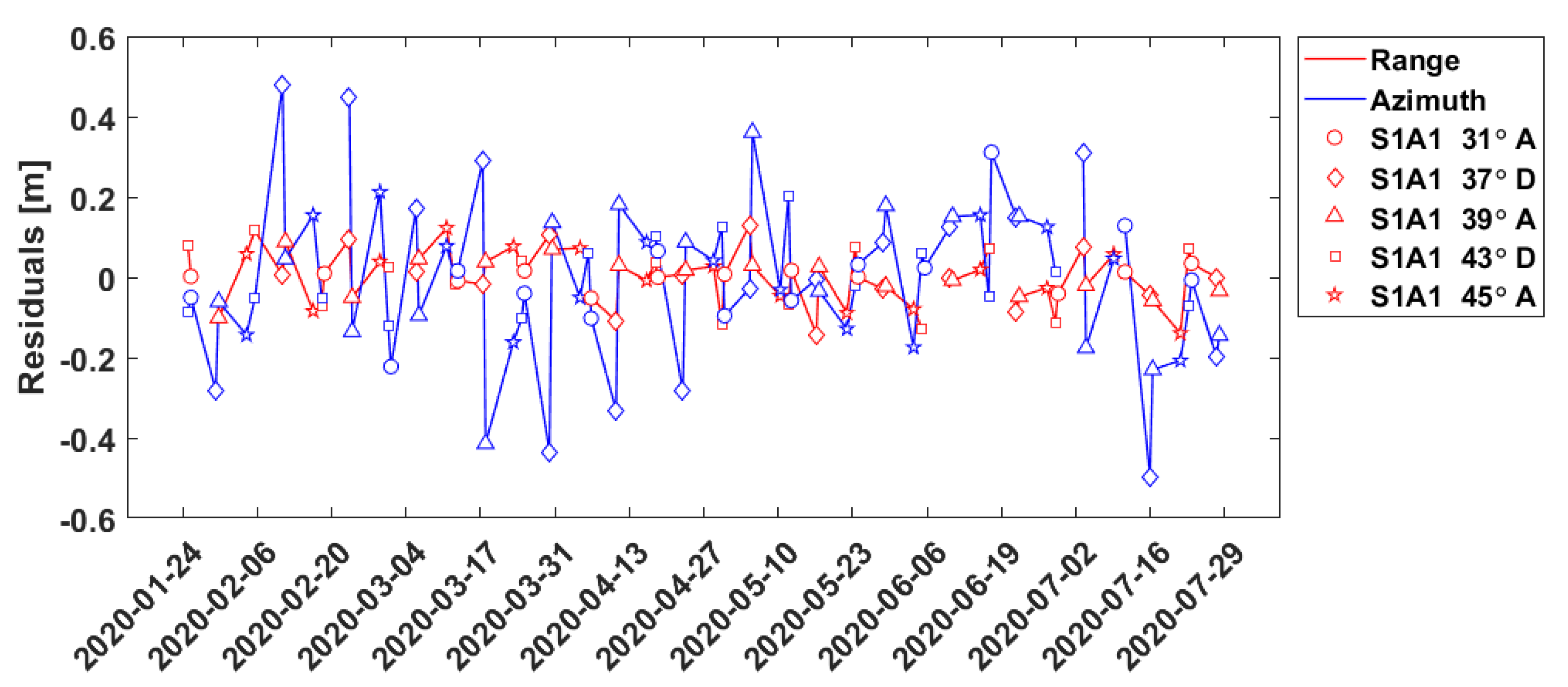
In a first approach we used the absolute positioning including geodynamic and atmospheric effects as well as systems effects of Sentinel-1 as described in the previous chapters. This attempt results in internal accuracies (estimated standard deviations) of two to three centimeters for the station of Emäsalo (Table 2). Moreover, the results for all stations show a likely incidence angle dependency, which can be inferred from the postfit residuals of the observations (Figure 8). This effect is noticeable for all range observations belonging to the same incidence angle class but less apparent for the azimuth observations, suggesting that another effect might also be present.

Table 2.
Estimated absolute coordinates and standard deviations for Emäsalo ECR station (ITRF2014): no compensation for outliers and biases per incidence angle.
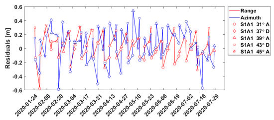
Figure 8.
Least squares minimized residuals of the range and azimuth observations without compensation for outliers and biases per incidence angle. The azimuth timings are expressed in meters by multiplication with the flight velocity of Sentinel 1. ECR station: Emäsalo, Finland. Solution type: absolute positioning; Legend: S1A1: Sentinel-1A image, Incidence angle in degrees, A/D: Ascending/Descending arc.
The second iteration of the coordinate estimation, which we refer to as refined absolute positioning, therefore additionally accounts for:
- Outlier detection per incidence angle: Outlier detection is performed per incidence angle, using a 3σ-median condition. The median is computed using all available observations taken from the same incidence angle. The detection is performed separately for azimuth and range observations.
- Incidence-angle dependent biases: Two biases (range, azimuth) are computed for each incidence angle class. This means that for an ECR that receives signal from 5 different incidence angles, 10 biases will be estimated in total. The biases are computed using the mean of all observations that have not been marked as outliers.
The marked range and/or azimuth observations are removed and the computed biases are applied to the respective azimuth and range input observations. The parameter estimation is performed again, this time accounting for the incidence angle-specific outliers and biases. The incidence angle treatment greatly improves the standard deviations of the positioning results (Table 3, line for Emäsalo) and reduces the residuals of the parameter estimation (Figure 9). Table 3 shows that with this refined outlier removal procedure standard deviation per coordinate axis of about one centimeter down to 3.4 millimeters for the Mårtsbo station can be achieved. It is important to point out that the computed absolute coordinates change either slightly (mm level) or not at all when compared to the coordinates from the initial solution. As expected, the application of the biases greatly benefits the range, since range is likely to be sensitive to elevation-dependent systematic effects but helps less the azimuth, whose times series shows a less stable, and possibly periodic, behavior.

Table 3.
Estimated absolute coordinates and standard deviations of the Baltic and DLR ECR stations (ITRF2014). * DLR2 corresponds to the station Oberpfaffenhofen 112, and DLR3 to Oberpfaffenhofen 113; #Images: Number of images used for SAR positioning.
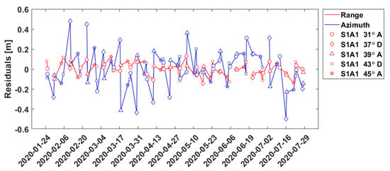
Figure 9.
Least squares minimized residuals of the range and azimuth observations with compensation for outliers and biases per incidence angle. The azimuth timings are expressed in meters by multiplication with the flight velocity of Sentinel 1. ECR station: Emäsalo, Finland. Solution type: refined absolute positioning. Legend: S1A1: Sentinel-1A image, Incidence angle in degrees, A/D: Ascending/Descending arc.
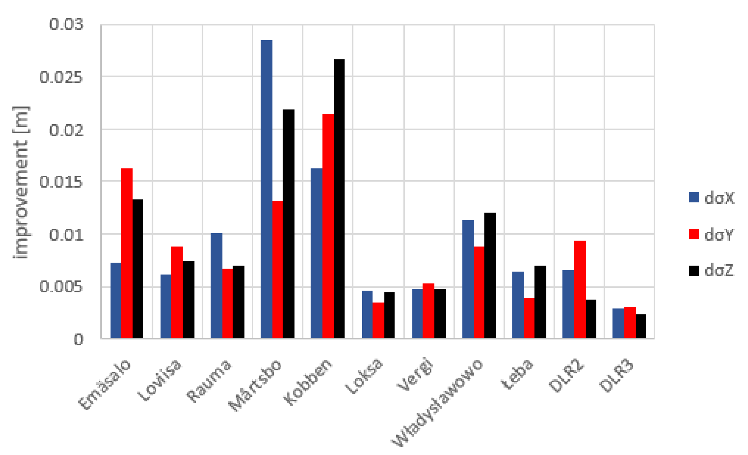
The results of this refined processing lead to an improvement of the standard deviations for all ECR stations but differ in amplitude per location, coordinate axis, and number of SAR scenes (Figure 10). While the benefit from the bias compensation is in general greater than the impact of the outlier removal, Emäsalo sees an improvement of up to 1 cm in sigma components simply from the removal of erroneous observations. An example of a station which mainly benefits from the bias compensation is Mårtsbo, which shows strong systematic biases for certain incidence angles. Mårtsbo sees an improvement of about 2.7 cm in x and 1.8 cm in the z direction when the observations are corrected for the estimated biases. In the particular station, the application of the biases along with the removal of outliers lead to significant improvement of the standard deviations of up to 2.85 cm in x direction (Figure 10).
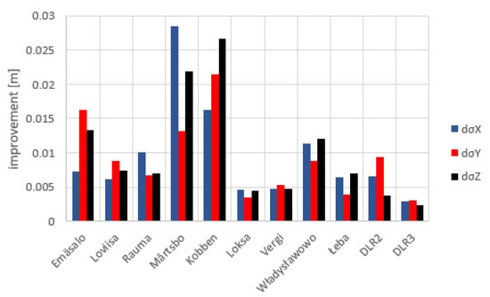
Figure 10.
Improvement of the refined absolute positioning standard deviations in the ITRF14 frame with respect to the original approach for all stations (differences of standard deviations dσ(X,Y,Z)).
In order to take a closer look at the results of the standard and refined positioning approach, we analyzed the full variance-covariance matrices of the coordinate solutions in terms of error ellipses in a local North-East-Up coordinate system. Again, Emäsalo was chosen to be discussed in more detail because there are many observations available and it shows a very stable and typical behavior that can be compared to other stations.
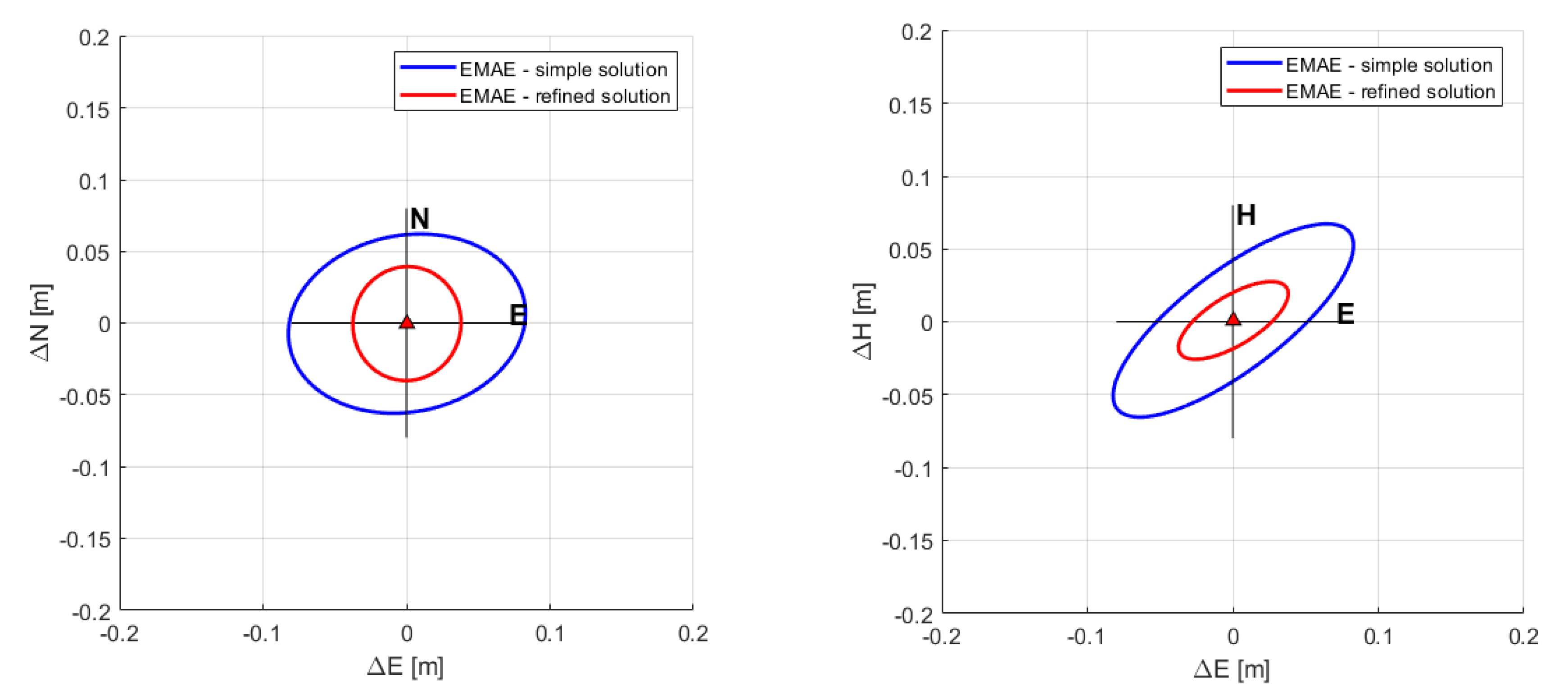
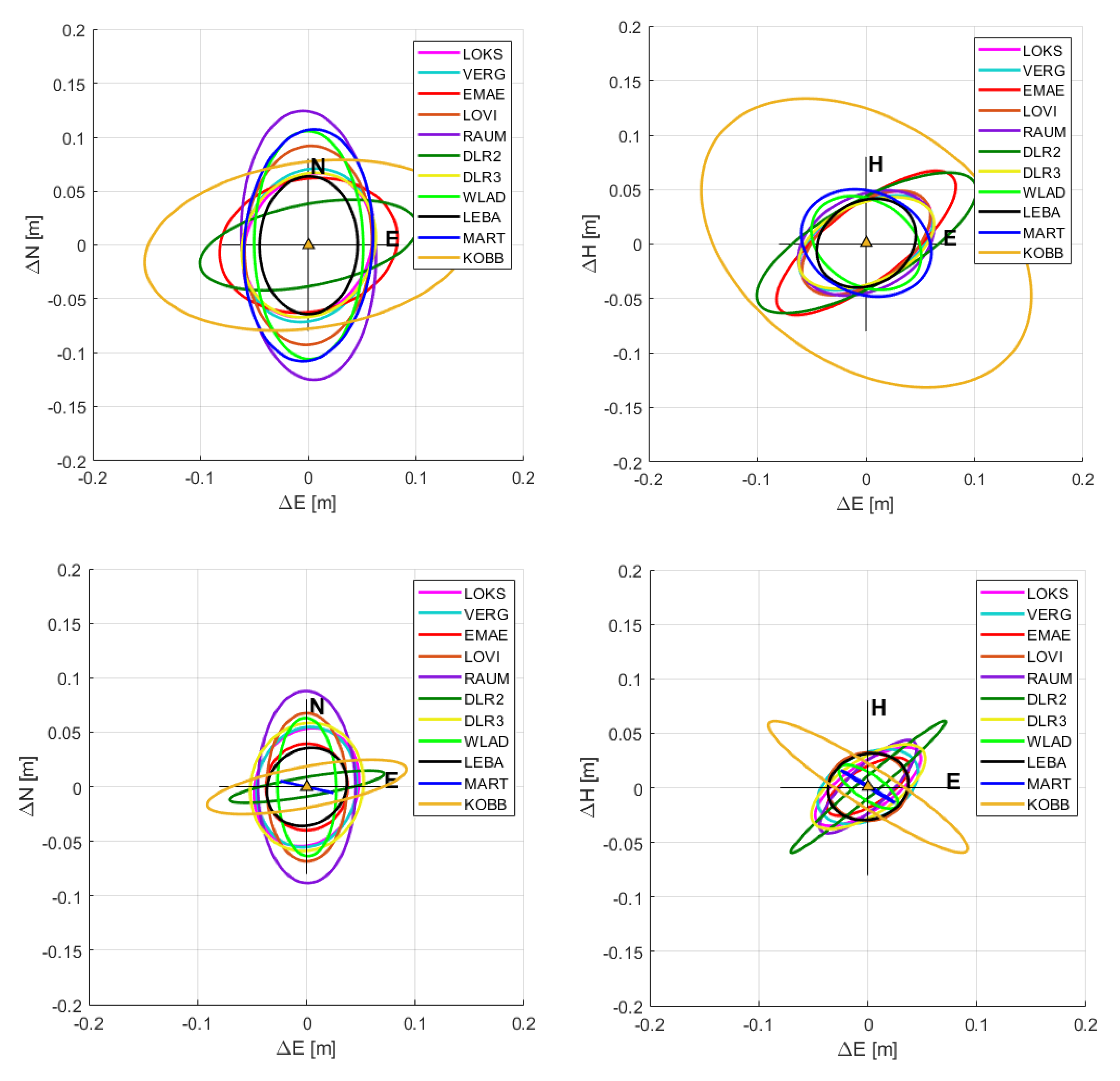
The improved standard deviations and covariances of the refined absolute positioning (Table 3) lead to a smaller, more circular error ellipse especially in the horizontal plane (Figure 11, left). In the vertical plain, the semimajor axis of the error ellipsoid is smaller but it still shows a high eccentricity (Figure 11, right). This development can be seen for all stations; the eccentricity of the error ellipses is reduced more in the horizontal plane (Figure 12, left column) than in the vertical and the semimajor axes decrease (Figure 12, right column). Furthermore, the effects of the refined processing on the residuals at Emäsalo (Figure 9) is a typical behavior that can be seen for all stations. The residuals for the azimuth observation only improve a little compared to the range observations that improve much more. The large difference between range and azimuth are observed because the bias computation treats both biases as constant. The azimuth observations show unstable, possibly periodic, behavior, which leads to little improvements of the azimuth residuals.
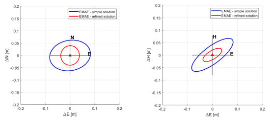
Figure 11.
95% confidence ellipsoids in the horizontal North-East (left) and vertical height-East (right) view computed for the ECR station at Emäsalo, Finland using the original (blue) and refined (red) absolute positioning technique. For the error ellipsoids, the estimated absolute coordinates are assumed to equal the true position.
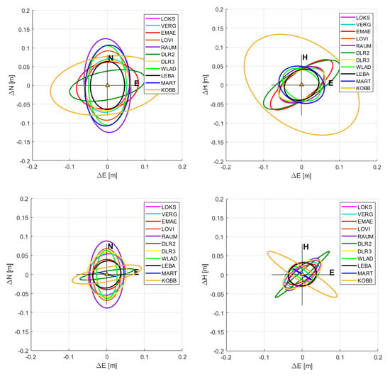
Figure 12.
95% confidence ellipsoids in the horizontal North-East (left column) and vertical height-East view (right column) computed for all ECR station in the Baltic Sea and at DLR using the original (upper row) and refined (bottom row) absolute positioning technique. For the error ellipsoids, the estimated absolute coordinates are assumed to equal the true position.
One of the parameters that needs to be taken into account when the quality of the solution is regarded is the detailed location of the installed ECR. While previous experiments have correctly shown that the ECR can be reliably measured in areas with low background noise, highly reflecting objects (e.g., metal structures) in the close vicinity of the instrument are likely to create responses, which can interfere with those from the ECR. This is most likely the case for Rauma, where the installed ECR has been placed close to metal reflectors. The data from the Rauma ECR had to be processed separately, in order to remove erroneous observations that seem to have resulted from nearby object(s) reflections. A total of nine false observations were successfully filtered out, but remaining interferences might still hinder the coordinate estimation result. In general, gross residuals might indicate unwanted reflections, which need to be carefully filtered out. On the other hand, instruments that have been placed in unobstructed locations with no background noise such as glades (e.g., Emäsalo, Mårtsbo) generally show better statistics. Another station with results that might require further investigation is Forsmark/Kobben, where the ECR is surrounded by a fence. Next to investigating these special cases, further improvement might be possible by treating the azimuth observations in a different way than the range observations.
Another point to consider is the fact that the ECR is an active instrument, requiring power supply and monitoring. So far, none of the ECRs experienced major functionality issues, except for one of the ECRs located at Oberpfaffenhofen (DLR2), which had to be repaired after failure at the end of February. The ECR is again back in operation, however, due to its different behavior after the repair (possible change of the instrument delays), we could only make use of the observations taken after resuming operations in June.
To further improve precision of the absolute positioning, the phase center offset of the transponders needs to be taken into account. One of the advantages of the ECRs with respect to the conventional CRs is its ability to track signals from both ascending and descending orbits. This functionality is supported by two pairs of antennas squinted in azimuth with respect to the edge of the ECR’s baseplate and tilted in elevation with respect to the zenith [27]. The phase centers of the antenna views are different between the two orbits. The positions of the two centers are provided in the reference system of the ECR. The different phase center positions of the ascending and descending antenna phase centers complicate the positioning. Offsets, expressed in terms of range and azimuth timings for the different incidence angles, shall be applied as internal system corrections to the input observations. The offset compensation is of particular importance when the external accuracy of the positioning is considered. Local surveys, in order to determine the absolute coordinates of reference points of all ECRs, have been completed or are planned to be done in the near future at all sites. The availability of these externally computed reference coordinates, along with the antenna phase offset corrections, will enable the absolute comparison of the estimated positions against the positions determined by the high precision GNSS survey campaigns.
4. Local Geoid Modeling
For observing the absolute sea level and enabling unification of height systems, physical heights of the tide gauge stations referring to a common equipotential surface are needed. This is achieved by combining a GOCE based Earth Gravity Model (EGM) with local/regional gravity data (land, airborne and/or marine) and a Digital Elevation Model (DEM). There are several methods that have been proposed and validated by the scientific community and they have so far not converged to a single state-of-the-art method [39]. Here, basically two regional geoid determination methods are planned to be compared, both in a pointwise sense at the tide gauges and over a rectangular area covering the tide gauges (comparison of regular grids). The methods are:
- Three-dimensional Least Squares Collocation (3D LSC method) [40,41,42], using the remove-compute-restore method with Residual Terrain Modeling (RTM) of the topographic corrections [43].
- Least squares modification of Stokes’ formula with additive corrections (LSMSA method), where the remove-compute-restore philosophy is used for gridding of the surface gravity anomalies; see e.g., [44,45,46,47].
Both methods are tested with the satellite-only EGMs GOCE –DIR6 [15] and GOCO06S [48]. Both models are based on the most recent collection of GOCE and GRACE satellite data and are available up to degree and order 300 of a spherical harmonic series. The algorithms implied by these two regional geoid determination methods are described in detail in the literature, for instance in the references given above.
To summarize, the main processing steps and algorithms to be applied are the following:
- Selection of local/regional gravity data from the Nordic Geodetic Commission (NKG) and Polish gravity databases and computation of surface gravity anomalies using the Geodetic Reference System 80 (GRS 80). The algorithms for the latter step are given in [49].
- To obtain a sufficient spectral overlap between the local/regional gravity and the satellite-only EGMs, gravity point data are selected from a rectangular gravity area overlapping the rectangular geoid area with at least 110 km in all directions (corresponding to 1-degree spherical distance in each direction). Two computation areas, one larger area over the Bay of Bothnia/Gulf of Finland (Sweden, Finland, and Estonia) and one smaller area surrounding the Polish tide gauges are foreseen. All methodological tests described below are made over the large main area.
- Computation of topographic RTM effects based on a Digital Elevation Model (DEM) using the algorithms in [43]. In this step, the NKG2015 DEM (called NKG_DEM2014) is used for Sweden, Finland, and Estonia, while for the other areas the SRTM3 [50] and GTOPO30 [51] DEMs are used (the latter for areas above 60° latitude). The RTM effect on the surface gravity anomaly is computed both for each gravity observation and for the gravity grid. The RTM effect on the height anomaly is computed for the geoid grid and for the tide gauge stations. As we are at or close to sea with limited topographic heights, the height anomaly is very close to the geoid height [52].
- Computation of the EGM effects for the gravity anomaly and height anomaly grids using the satellite-only EGMs. This is standard synthesis of solid spherical harmonics; see for instance [53]. An important parameter here is the maximum degree used for the synthesis. This parameter is chosen based on numerical tests with respect to the NKG2015 GNSS/leveling height anomalies in the large geoid area.
- Computation of reduced surface gravity anomalies by subtracting the EGM and RTM effects. Gross error detection is made using cross validation exactly as described in [54].
- For the LSMSA method: The surface gravity anomalies are gridded using Least Squares Collocation (LSC) with a 2nd order Gauss–Markov covariance function. After that, the RTM gravity anomaly grid is restored to get gridded surface gravity anomalies. All details can be found in [54].
- For the LSMSA method: the final geoid heights (height anomalies) are computed using the LSMSA method as implemented in [46], which is also summarized in [54]. The least squares modification of Stokes’ formula is chosen according to the formulation in [44]. The most crucial parameter choices here are to choose as realistic signal and noise degree variances as possible (for the EGM and for the local/regional gravity data). The chosen parameters are validated using GNSS/leveling data.
- For the 3D LSC method: the reduced height anomaly is computed using to the well-known standard formulas of three-dimensional LSC [40]. An empirical covariance function is estimated from the reduced gravity anomalies, to which a Tscherning-Rapp covariance function [41] is then fitted [42]. The standard uncertainties of the observations are taken from the NKG2015 version of the NKG gravity database. To speed up the grid computations, the large height anomaly grid is divided into small 1 x 1-degree grids with some small overlap, which are finally merged to obtain the final height anomaly grid. The point height anomalies in the tide gauges are computed without this approximation and compared to the grid values.
- For the 3D LSC method: the final geoid height (height anomaly) is computed by restoring the EGM and RTM effects, both pointwise in the tide gauges and grid wise.
- The standards to be applied for consistent combination with geometric heights are followed for both methods. The standards are the same as in the NKG2015 geoid model project implying zero permanent tide system and postglacial land uplift epoch 2000.0. Besides, the W0 value is chosen to the values obtained in the NKG2015 project (W0 = 62,636,858.18 m2/s2).
- The tested methods, EGMs, and parameter choices are evaluated in a relative sense using Finnish, Swedish, and Estonian GNSS/leveling height anomalies (inside the large geoid area over the northern/middle Baltic Sea including parts of Gulf of Finland). The GNSS/leveling should refer either to the national realizations of the European Vertical Reference System (EVRS) with postglacial land uplift epoch 2000.0 or to EVRF2007 (as for Poland). The GNSS observations in question must also be transformed from nontidal to zero permanent tide system.
The methods above aim for absolute geoid heights (height anomalies) at standard epoch 2000.0. Two methods will be evaluated to compute the geoid variation. The first is to take the geoid change from the official NKG2016LU postglacial land uplift model [55], while the second is to compute it based on the GRACE Follow-on mission. The computations and tests are done in the following way:
- The NKG2016LU model will be used to convert the absolute geoid heights from epoch 2000.0 to the mean epoch for the SAR data analysis period.
- Then the NKG2016LU is compared with Grace Follow-on for the period covered with SAR observations. The study is limited to evaluating monthly mean values from one Science Data System center, namely GFZ (Helmholtz Centre Potsdam German Research Centre for Geosciences) [56].
Spherical harmonic synthesis is performed at all tide gauge locations and the corresponding geoid time series is computed and analyzed. The long term geoid change in the large area is around 0.2–0.6 mm/year [55].
Computations are not yet completed but with the very good gravity data coverage in the Baltic Sea and the high quality satellite-only EGMs it is expected that a 1 cm geoid accuracy can be achieved. As described, time variability of the geoid due to VLM is very small, hence negligible for the purpose of the present project. Regarding the data sequence of SAR observations for the installed ECRs (Table 1), time variability of the geoid is far below the 1 cm amplitude and therefore does not need to be considered. On a longer perspective also time variability of the geoid needs to be taken into account when combining this information with geometric heights from SAR and tide gauge readings for computing absolute sea level heights and unifying height systems across the oceans.
5. Tide Gauge Data, Combination of Heights, and Reference System Issues
5.1. Tide Gauge Data Analysis
Sea level at the coastline is observed with tide gauges that deliver instantaneous sea surface heights relative to a zero marker of the tide gauge station. Contemporary automatic sea level gauge stations track water level changes continuously and are capable via data communication devices to transfer data in real-time. Since the sea level observations are mainly used for marine navigation then most commonly the tide gauges are installed at harbors, where the necessary infrastructure exists. All the participating tide gauge stations shown in Table 1 utilize automatic sea level detection (e.g., pressure or radar gauges, stilling well with float, etc.). It is important to identify whether the tide gauge authority delivered data set is raw or is corrected to account for certain phenomena, e.g., ocean and Earth tides.
The same time sampling intervals are used for each tide gauge station. The standard hourly tide gauge data are the primary data set used for analysis. The advantage of the hourly data is that these contain no high frequency noise (i.e., sudden spikes in the time series) which usually is eliminated by the averaging procedure. For reliable mean sea level (MSL), estimation of the sea level measurements should be performed over an adequate time period to filter out data blunders and obtaining statistically meaningful results. An annual water cycle period is assumed to be sufficient for the purpose of the present study. Alternatively, also seasonal MSL estimates are tested.
The accuracy of contemporary tide gauge readings remains within 0.2…1.0 cm. However, readings of such sensors need to be compensated due the instrumental phenomena, e.g., drift [57]. Accordingly, the tide gauge data received from the tide gauge authorities are checked for the inclusion of such instrumental corrections. The drift corrected data are to be further filtered in order to remove data blunders and gross errors. In order to filter out data blunders the tide gauge series are statistically analyzed. Data gaps (e.g., due to malfunctioning of instruments) in tide gauge data series also may occur. The standard deviation (STD) of the readings reflects the inner consistency (for the entire period, or seasonally) of the time series at each tide gauge station. Typically, the larger STD is associated with the rougher sea conditions at individual stations, whereas the smaller STD may also reveal sea sheltered locations.
The final mean sea level for the participating tide gauges is to be computed centrally, applying the same methodology and considering also interconnections (e.g., local ties by precise levelings, GNSS) between the tide gauges and geodetic infrastructure [58]. For the consistency of the tide gauge analysis it is requested that data are presented in the same sea level datum. These resulting data series will serve as an input for the processing of corrected Tide Gauge Sea Level Heights. The MSL at individual tide gauges are then to be uniquely determined from these corrected tide gauge records.
After eliminating ocean and Earth tides from the observations, one obtains a time series of sea heights and consequently its changes. The same models and standards need to be applied as they are used for the geometric and gravimetric heights. These height changes, as they are observed at the tide gauges, at this point are relative changes of the sea surface with respect to the zero marker. These zero markers need to be tied to the geometric network, simultaneously determining height differences to the ECRs and/or GNSS stations. The obtained vertical offsets need to be taken into account during the combination (see Section 5.2).
5.2. Computation of Absolute Sea Level Heights
In order to compute absolute sea level heights for tide gauge markers with respect to a chosen physical height reference system (an equipotential surface), all individual observation types need to be combined in a consistent way securing that common standards are applied during all processing steps (see Section 5.3). For a defined epoch t, the formula to compute an absolute sea level height reads as follows:
- with:
- Height of tide gauge zero marker above reference ellipsoid at epoch t (ellipsoidal height) (from SAR or GNSS, Section 3)
- Height of reference equipotential surface above reference ellipsoid at tide gauge location at epoch t (geoid height/height anomaly, Section 4)
- Tide gauge sea level height above tide gauge zero marker at epoch t (relative sea level) (Section 5.1)
- Sea level height above reference equipotential surface at epoch t (absolute sea level height)
If we target for physical heights at a tide gauge station referring to a unique reference equipotential surface at an epoch t and not considering the absolute or relative sea level, we can apply the following formula:
- with:
- Physical height of tide gauge zero marker above reference equipotential surface
In case an offset of the tide gauge zero marker physical height with respect to the physical height given in the national or regional height system is present, leveled heights from the national/regional height system reference marker to the tide gauge zero marker are needed. These offsets then can be further used to unify national or regional height systems, making use of an existing national/regional height reference network.
5.3. Reference Frames and Joint Standards
As introduced earlier, it is of utmost importance to use the same numerical standards and models for processing and correcting the coordinates (heights), which are observed with the different techniques. In addition, they all need to be transformed into the same reference frame before they can be combined with the equations above.
It is well known that different sets of numerical standards are in use in geodesy. Table 4 provides an overview for some numerical values specified in different conventions and typically used in geodesy. This has to be considered when combining the different geometric and gravimetric quantities. The same holds for tide and time systems, which are not uniquely defined for the different geodetic quantities. While gravimetric products, such as the satellite-only gravity field models, are given in the zero-tide system (in agreement with IAG resolution No. 16 of the 18th General Assembly 1983), the geometric quantities, such as the ITRF, are given in the conventional tide free system. The difference between these two tide systems is latitude dependent, and this effect is more than 10 cm for station heights in the Baltic Sea area. The formulae for the transformation between different tide systems are provided in Section 7 of the IERS Conventions 2010 [36]. For the transformation of 3-D Cartesian coordinates into ellipsoidal coordinates, the conventional GRS80 parameters shall be used for all the different observation types and products to ensure consistency of the combination results. For example, the difference for the equatorial radius between GRS80 and the IERS Conventions 2010 is about 40 cm. It is also strongly recommended to use the conventional W0 value (IAG 2015) as the reference value for the geopotential at the geoid. More details on standards-related issues are provided in the inventory of standards and conventions compiled by the GGOS Bureau of Products and Standards [59].

Table 4.
Overview on numerical standards that are relevant for the combination of coordinates [59].
Furthermore, also the background models and standards used for the processing of the different geometric and gravimetric quantities need to be consistently applied. The IERS Conventions 2010 shall be applied for the processing of the different observations [36]. Moreover, individual technique-specific standards need to be considered for the processing of the GNSS data (IGS- and EPN-Standards), the SAR data (SAR standards), the tide gauge data (EUROGOOS, BOOS, PSMSL), and the gravimetric quantities (IAG Resolutions No. 1/2, 2015; GOCE Standards).
In summary, the standards used for the different data types and products need to be clearly documented, and in the case of any deviations regarding numerical standards, time, or tide systems, transformations between different sets have to be performed to get consistent results. Furthermore, also the background models and processing standards need to be consistently applied for the different observation types.
In the context of global reference frames, there are the three following issues, which are important for the combination of geometric and gravimetric heights (Equation (11)):
- Nonlinear station motions: The ITRF realizations are primarily based on a linear model (station positions and constant velocities), and thus, nonlinear motions are visible in the station position residuals. The time series analysis of station positions reveals nonlinear motions of several millimeters or even more (up to a few centimeters) for some stations, which are caused by various effects such as neglected surface loading, e.g., [60]. These nonlinear station motions may cause errors in the order of a few millimeters when transforming the (regional) GNSS or SAR positioning solutions into the global reference frame. This is a dominating error source, which can affect the combinations and comparisons of different geometric and gravimetric quantities. Thus, this needs to be considered, e.g., by using the periodic signals of the ITRF2014 results (available on request from IGN [61], by using the DTRF2014 results, which consider for the first time nontidal loading corrections, [62], and by using geophysical models for the atmospheric, hydrological, and oceanic loading from the Global Geophysical Fluids Center (GGFC) or from other available sources.
- Extrapolation of ITRF results: The ITRF2014 and DTRF2014 contain data until the end of 2014. If GNSS (or SAR) solutions (processed for example in 2020) need to be transformed to the global reference frame, the station positions must be extrapolated over a time period of about ten years, since the reference epoch of ITRF2014 station positions is 2010.0. Assuming that station velocities may have an error of 2 mm/yr, the required extrapolation will cause a position error of about 2 cm. Since the nonlinear effects in station position time series (as discussed above) are visible mainly in the height components, this issue is critical.
- Realization of the ITRF origin, Center of Mass (CM) versus Center of Figure (CF): The ITRF origin is realized by SLR observations. Through the orbit dynamics, SLR determines the Center of Mass (CM). According to the IERS Conventions 2010 [36], the ITRF2014 (and DTRF2014) origin follows the mean Earth center of mass, averaged over the time span of SLR observations used and modeled as a secular (linear) function in time. The ITRF2014 provides an annual geocenter motion model derived from the same SLR data that defines the ITRF2014 long-term origin [61]. The DTRF2014 delivers the time series of the SLR translation parameters as an additional product [62], and the JTRF2014 realizes the origin at the quasi-instantaneous CM as sensed by SLR [63]. For further comparisons, also the multisatellite SLR solution computed at DGFI-TUM could be used within this project [60].
For the case study in the Baltic Sea, also regional and national reference frames (e.g., EUREF, GREF, SWEPOS) and transformations between them are involved. The orientation rate of the ITRF is aligned to that of the geophysical no-net-rotation model (NNR-NUVEL-1A), whereas for EUREF the European Terrestrial Reference System 89 (ETRS89) has been adopted in 1990. The ETRS89 definition follows two conditions:
- The ETRS89 coincides with the ITRS at epoch 1989.0. This condition leads to consider that the 7 transformation parameters between ITRS and ETRS89 are all zeros at epoch 1989.0.
- The ETRS89 is fixed to the stable part of the Eurasian tectonic plate. This condition implies that the ETRS89 is comoving with the Eurasian tectonic plate, hence defining its time evolution. Therefore, the time derivatives of the seven parameters between ITRS and ETRS89 are zeros, except the three rotation rates. The three rotation rates are in fact the three components of the Eurasia angular velocity in the ITRFyy frames.
6. Summary, Conclusions, and Future Work
The paper describes the concept for an observing system, which connects tide gauges with global geometric and physical height reference networks in order to determine absolute sea level heights, which further can be used for connecting height systems across oceans. Absolute means that sea level time series at different locations refer to a unique equipotential surface and that they can be further analyzed for quantifying water mass redistribution due to climate change by ice sheet melting, river discharge, and other phenomena. Very crucial for such an observing system is the monitoring of the tide gauge stations for vertical movements, as this signal one to one enters to sea level observations. In addition, the determination of the physical heights of the tide gauge stations relative to a globally defined equipotential surface is of great importance. Vertical movements and physical heights can be observed by a permanent GNSS receiver next to the tide gauge station and by modeling the local geoid at the station.
Only a few tide gauge stations nowadays are permanently equipped with GNSS receivers. Therefore, as a new technique, the 3D geodetic SAR positioning with active transponders is introduced. With this technique, ellipsoidal coordinates of the tide gauge stations can be observed continuously with relative little effort and it can be used to densify existing permanent GNSS networks. Geodetic SAR uses images taken by the Sentinel-1 satellites, which are an element of the European Commission´s Copernicus system and which guarantees long-term free of charge access to this information. The effort and costs for installing, maintaining, and operating active SAR transponders is much less than for a permanent GNSS receiver. Once such a transponder is in operation, data are collected via the Sentinel-1 satellites and there is no need to store and transmit data from the station to a data archive.
With the latest results from ESA´s gravity field mission GOCE and supporting missions such as GRACE and GRACE Follow-On, which are mainly used for observing temporal variations of the gravity field, nowadays a global static equipotential surface with 100 km spatial resolution and 1 cm accuracy is available. The time variable geoid is available on a monthly basis with similar accuracy but with a lower spatial resolution of about 300 km. These models together with local gravity observations are the basis for the geoid refinement at the tide gauge stations and the determination of possible temporal variations.
In order to determine absolute sea level heights, finally three different heights need to be combined (tide gauge records, ellipsoidal heights, geoid heights). To avoid systematic errors in the resulting absolute sea level heights, it is necessary to use the same standards and reference systems for all components. Here specifically identical background models and the relation of the geometric and physical origins of the Earth need to be considered and correct transformations need to be applied.
For a feasibility study, an observing system including a number of active SAR transponders has been installed by the project team in the Baltic Sea area. All in all, 12 transponders are installed, where seven of them are directly linked to tide gauge stations in Sweden, Finland, Estonia, and Poland, while three are installed at permanent GNSS stations within some tens of kilometers from a tide gauge station. The latter are planned to be used for relative positioning between the GNSS network and the tide gauges via the SAR stations. Two more stations are installed at a calibration site, where a permanent GNSS station is nearby and where also conventional passive corner reflectors are available. So far 11 stations are active and are providing data since the beginning of 2020. The project team has identified a number of experiments to be performed once a longer time series is available. These include transponder calibration, absolute positioning at collocated GNSS and/or tide gauge stations, short baseline coordinate transfer from GNSS to tide gauge stations, long baseline coordinate transfer across the sea, tide gauge linking between two nearby stations, and absolute versus relative coordinate transfer between neighboring transponder stations.
So far only absolute positioning experiments for 11 stations have been performed in order to identify the performance of the active transponders in the sense of achievable internal accuracies. For this the complete processing chain from the SAR image point target analysis, via the estimation of Sentinel-1 systematic corrections, atmospheric delay and solid Earth corrections to the SAR absolute positioning was applied. From the analyses of the first months of observations (up to six months), the following conclusions can be derived. The internal accuracy of 3D absolute positions applying a simple outlier detection procedure is at a level of about 4.3 cm for the station in Emäsalo. From the analysis of postfit residuals, it turned out that range residuals depend on the incidence angle at which the radar image was taken. Therefore, an outlier detection procedure per incidence angle class was developed and biases per incident angle class were computed in addition. This resulted in a significantly improved internal 3D position accuracy of about 2.1 cm for the Emäsalo station. For all other stations, similar improvement rates could be observed. Similarly, postfit residuals decreased for the range observations, while there are still some periodic signals visible in the azimuth residuals. The latter needs more investigations in order to optimize the estimation procedure. From the variance-covariance matrices of the 3D position solutions, error ellipses can be computed and analyzed in a local horizontal coordinate system (North-East-Height). By this the height errors in each direction can be extracted, which is important to quantify the resulting uncertainties of absolute sea level heights. Ideally, one would expect mostly circular error ellipses, meaning that in all directions the same accuracy is available. In case the ellipse is more oblate, the accuracies vary with respect to the direction, which might again result from phase center variations of the ECR. In addition, these results need to be analyzed more deeply once a longer data span is available.
The absolute positions themselves are very stable disregarding the applied approach. This is an indicator that the absolute coordinate estimation is robust and that it delivers meaningful results. At this point systematic comparisons with collocated GNSS or conventional corner reflector station coordinates have not been performed yet. These are needed in order to determine the absolute errors of the estimated coordinates. First results from tests at the DLR station exhibit some systematic differences, which might be caused by uncertainties in the phase center definition of the ECRs and/or by possible instrument delay biases, or a combination of both. This needs to be investigated at the collocation sites of the station network. Another lesson learned from the analyses is that ECR locations need to be selected very carefully and that possible other artificial reflectors need to be avoided. This is very visible in the data acquired from the Rauma station, where some metal containers are placed nearby the ECR and strongly disturb the ECR reflections.
Local geoid modeling, tide gauge data analysis, and the combination of all results in order to determine absolute sea level heights has not been performed yet, as the primary goal at this stage is to identify first the achievable internal accuracies of the transponder positioning with the geodetic SAR technique. The processors for local geoid refinement and tide gauge data processing are already in place and tested. What is still missing is the identification of possible transponder related systematic effects, which could be visible in the positioning results. In conclusion, future work to be performed after having about one year of SAR observations available will include the following analyses: (1) Refinement of SAR positioning for phase center variations due to satellite-ground station geometry and electronic antenna behavior; (2) Relative SAR positioning and comparison to results from absolute positioning; (3) Calibration of transponder positioning versus GNSS positions and identification of possible systematic delays; (4) Local geoid refinement at the tide gauge stations; (5) Processing tide gauge observations with identical setup and applying same background models; (6) Transformation of coordinates from all three observation systems into a unique reference frame; (7) Computation of absolute sea level heights at tide gauge stations and identification of possible systematic height system offsets between stations at two different countries; (8) Validation of height system differences by means of comparison to leveled heights at tide gauge stations.
As identified, there is still a lot to be done before absolute sea level heights can be computed for the testbed in the Baltic Sea. However, once the performance of the SAR transponder positions meets the 1 cm requirement in height, we think that this new type of instrument can help to observe vertical movement of tide gauge stations in a more systematic way than it is done now. Then tide gauges can also be used for determining the absolute sea level instead of observing only relative changes of the sea level with respect to the tide gauge zero marker.
Author Contributions
Conceptualization, T.G.; Data curation, A.E. (Artu Ellmann), C.G., L.J., S.M., F.N., A.E. (Andreas Engfeldt), X.O., T.S., M.S., A.Ś., S.V., and R.Z.; Methodology, T.G., J.Å., D.A., A.E. (Artu Ellmann), C.G., J.N., X.O., and M.P.; Project administration, T.G.; Resources, A.E. (Andreas Engfeldt), C.G., L.J., S.M., F.N., T.S., A.Ś., S.V., and R.Z.; Software, M.S.; Writing—original draft, T.G., J.Å., D.A., A.E. (Artu Ellmann), C.G., J.N., X.O., M.P., and R.Z. All authors have read and agreed to the published version of the manuscript.
Funding
This research partially was funded by European Space Agency (ESA), Grant number 4000126830/19/I-BG in the program BALTIC+ EXPRO+ Theme 5: Geodetic SAR for Baltic Height. Tallinn University of Technology research is partly funded by the Estonian Science Council grant PRG330.
Acknowledgments
Apart from the authors, the following people from the contributing institutions supported the local installation of the ECRs: Markus Heinze (TUM), Tomasz Kur (CBK-PAN), Adam Lyszkowicz (CBK-PAN), Janusz B. Zielinski (CBK-PAN). In addition, the authors acknowledge the support of the following agencies and institutions: The Geodesy department of the Estonian Land Board is thanked for installation assistance of the Estonian ECR sites.
Conflicts of Interest
The authors declare no conflict of interest.
References
- Church, J.A.; White, N.J. Sea-Level Rise from the Late 19th to the Early 21st Century. Surv. Geophys. 2011, 32, 585–602. [Google Scholar] [CrossRef]
- Meyssignac, B.; Cazenave, A. Sea level: A review of present-day and recent-past changes and variability. J. Geodyn. 2012, 58, 96–109. [Google Scholar] [CrossRef]
- Stammer, D.; Cazenave, A. Satellite Altimetry over Oceans and Land Surfaces; CRC Press: Boca Raton, FL, USA, 2017; ISBN 978-1-315-15177-9. [Google Scholar]
- Nerem, R.S.; Chambers, D.P.; Choe, C.; Mitchum, G.T. Estimating Mean Sea Level Change from the TOPEX - and Jason Altimeter Missions. Mar. Geod. 2010, 33, 435. [Google Scholar] [CrossRef]
- Woodworth, P.L.; Player, R. The Permanent Service for Mean Sea Level: An Update to the 21stCentury. J. Coast. Res. 2003, 19, 287–295. [Google Scholar]
- Wöppelmann, G.; Marcos, M.; Santamaría-Gómez, A.; Martín-Míguez, B.; Bouin, M.-N.; Gravelle, M. Evidence for a differential sea level rise between hemispheres over the twentieth century. Geophys. Res. Lett. 2014, 41, 1639–1643. [Google Scholar] [CrossRef]
- Wöppelmann, G.; Martin Miguez, B.; Bouin, M.-N.; Altamimi, Z. Geocentric sea-level trend estimates from GPS analyses at relevant tide gauges world-wide. Glob. Planet. Chang. 2007, 57, 396–406. [Google Scholar] [CrossRef]
- Santamaría-Gómez, A.; Gravelle, M.; Collilieux, X.; Guichard, M.; Míguez, B.M.; Tiphaneau, P.; Wöppelmann, G. Mitigating the effects of vertical land motion in tide gauge records using a state-of-the-art GPS velocity field. Glob. Planet. Chang. 2012, 98–99, 6–17. [Google Scholar] [CrossRef]
- Woodworth, P.L.; Hughes, C.W.; Bingham, R.J.; Gruber, T. Towards worldwide height system unification using ocean information. J. Geod. Sci. 2012, 2, 302–318. [Google Scholar] [CrossRef]
- Gruber, T.; Gerlach, C.; Haagmans, R. Intercontinental height datum connection with GOCE and GPS-levelling data. J. Geod. Sci. 2012, 2, 270–280. [Google Scholar] [CrossRef]
- Collilieux, X.; Wöppelmann, G. Global sea-level rise and its relation to the terrestrial reference frame. J. Geod. 2011, 85, 9–22. [Google Scholar] [CrossRef]
- Wöppelmann, G.; Letetrel, C.; Santamaria, A.; Bouin, M.-N.; Collilieux, X.; Altamimi, Z.; Williams, S.D.P.; Miguez, B.M. Rates of sea-level change over the past century in a geocentric reference frame. Geophys. Res. Lett. 2009. [Google Scholar] [CrossRef]
- Wöppelmann, G.; Marcos, M. Coastal sea level rise in southern Europe and the nonclimate contribution of vertical land motion. J. Geophys. Res. Ocean. 2012, 117. [Google Scholar] [CrossRef]
- Brockmann, J.M.; Schubert, T.; Mayer-Gürr, T.; Schuh, W.-D. The Earth’s Gravity Field as Seen by the GOCE Satellite—An Improved Sixth Release Derived with the Time-Wise Approach; GFZ Data Services, 2019; Available online: https://dataservices.gfz-potsdam.de/icgem/showshort.php?id=escidoc:4315891 (accessed on 13 November 2020).
- Förste, C.; Abrykosov, O.; Bruinsma, S.; Dahle, C.; König, R.; Lemoine, J.-M. ESA’s Release 6 GOCE Gravity Field Model by Means of the Direct Approach Based on Improved Filtering of the Reprocessed Gradients of the Entire Mission; GFZ Data Services, 2019; Available online: https://gfzpublic.gfz-potsdam.de/pubman/faces/ViewItemFullPage.jsp?itemId=item_4495891_2&view=EXPORT (accessed on 13 November 2020).
- Brooks, B.A.; Merrifield, M.A.; Foster, J.; Werner, C.L.; Gomez, F.; Bevis, M.; Gill, S. Space geodetic determination of spatial variability in relative sea level change, Los Angeles basin. Geophys. Res. Lett. 2007, 34. [Google Scholar] [CrossRef]
- Eineder, M.; Minet, C.; Steigenberger, P.; Cong, X.; Fritz, T. Imaging Geodesy—Toward Centimeter-Level Ranging Accuracy with TerraSAR-X. IEEE Trans. Geosci. Remote Sens. 2011, 49, 661–671. [Google Scholar] [CrossRef]
- Balss, U.; Gisinger, C.; Cong, X.Y.; Brcic, R.; Steigenberger, P.; Eineder, M.; Pail, R.; Hugentobler, U. High resolution geodetic earth observation with TerraSAR-X: Correction schemes and validation. In Proceedings of the 2013 IEEE International Geoscience and Remote Sensing Symposium—IGARSS, Melbourne, Australia, 21–26 July 2013; pp. 4499–4502. [Google Scholar]
- Gisinger, C.; Balss, U.; Pail, R.; Zhu, X.X.; Montazeri, S.; Gernhardt, S.; Eineder, M. Precise Three-Dimensional Stereo Localization of Corner Reflectors and Persistent Scatterers With TerraSAR-X. IEEE Trans. Geosci. Remote Sens. 2015, 53, 1782–1802. [Google Scholar] [CrossRef]
- Gisinger, C.; Schubert, A.; Breit, H.; Garthwaite, M.; Balss, U.; Willberg, M.; Small, D.; Eineder, M.; Miranda, N. In-Depth Verification of Sentinel-1 and TerraSAR-X Geolocation Accuracy Using the Australian Corner Reflector Array. IEEE Trans. Geosci. Remote Sens. 2020, 1–28. [Google Scholar] [CrossRef]
- Mahapatra, P.S.; Samiei-Esfahany, S.; van der Marel, H.; Hanssen, R.F. On the Use of Transponders as Coherent Radar Targets for SAR Interferometry. IEEE Trans. Geosci. Remote Sens. 2014, 52, 1869–1878. [Google Scholar] [CrossRef]
- Gisinger, C.; Willberg, M.; Balss, U.; Klügel, T.; Mähler, S.; Pail, R.; Eineder, M. Differential geodetic stereo SAR with TerraSAR-X by exploiting small multi-directional radar reflectors. J. Geod. 2017, 91, 53–67. [Google Scholar] [CrossRef]
- Bloßfeld, M.; Müller, H.; Gerstl, M.; Štefka, V.; Bouman, J.; Göttl, F.; Horwath, M. Second-degree Stokes coefficients from multi-satellite SLR. J. Geod. 2015, 89, 857–871. [Google Scholar] [CrossRef]
- Poutanen, M.; Kakkuri, J. Final Results of the Baltic Sea Level 1997 GPS Campaign; Reports; Finnish Geodetic Institute: Helsinki, Finland, 1999; 182p. [Google Scholar]
- Kakkuri, J. Final Results of the Baltic Sea Level 1993 Campaign; Reports; Finnish Geodetic Institute: Helsinki, Finland, 1995. [Google Scholar]
- Sentinel High Level Operations Plan (HLOP)—Sentinel 1 SAR Document Library—User Guides—Sentinel Online. Available online: https://sentinel.esa.int/web/sentinel/user-guides/sentinel-1-sar/document-library/-/asset_publisher/1dO7RF5fJMbd/content/sentinel-high-level-operations-plan (accessed on 22 September 2020).
- di Meo, P.; Pausini, M.; Carnavale, G.; Trampuz, C.; Meta, A. ECR-C User Manual; Issue 1.6; MetaSensing BV: Noordwijk, The Netherlands, 2019. [Google Scholar]
- Cumming, I.G.; Wong, F.H. Digital Processing of Synthetic Aperture Radar Data; Artech House: London, UK, 2005; ISBN 978-1-58053-058-3. [Google Scholar]
- Piantanida, R.; Recchia, A.; Franceschi, N.; Valentino, A.; Miranda, N.; Schubert, A.; Small, D. Accurate Geometric Calibration of Sentinel-1 Data. In Proceedings of the EUSAR 2018—12th European Conference on Synthetic Aperture Radar, Aachen, Germany, 4–7 June 2018; pp. 1–6. [Google Scholar]
- Landskron, D.; Böhm, J. VMF3/GPT3: Refined discrete and empirical troposphere mapping functions. J. Geod. 2018, 92, 349–360. [Google Scholar] [CrossRef]
- Landskron, D.; Böhm, J. Refined discrete and empirical horizontal gradients in VLBI analysis. J. Geod. 2018, 92, 1387–1399. [Google Scholar] [CrossRef] [PubMed]
- Kouba, J. Implementation and testing of the gridded Vienna Mapping Function 1 (VMF1). J. Geod. 2008, 82, 193–205. [Google Scholar] [CrossRef]
- Schaer, S. Mapping and Predicting the Earth’s Ionosphere Using the Global Positioning System. Institut für Geodäsie und Photogrammetrie Eidg; Technische Hochschule Zürich: Zürich, Switzerland, 1999; ISBN 9783908440017. [Google Scholar]
- Hernández-Pajares, M.; Juan, J.M.; Sanz, J.; Orus, R.; Garcia-Rigo, A.; Feltens, J.; Komjathy, A.; Schaer, S.C.; Krankowski, A. The IGS VTEC maps: A reliable source of ionospheric information since 1998. J. Geod. 2009, 83, 263–275. [Google Scholar] [CrossRef]
- Balss, U.; Cong, X.Y.; Brcic, R.; Rexer, M.; Minet, C.; Breit, H.; Eineder, M.; Fritz, T. High precision measurement on the absolute localization accuracy of TerraSAR-X. In Proceedings of the 2012 IEEE International Geoscience and Remote Sensing Symposium, Munich, Germany, 22–27 July 2012; pp. 1625–1628. [Google Scholar]
- Petit, G.; Luzum, B. IERS—IERS Conventions (2010); IERS Technical Note No. 36; Verlag des Bundesamts für Kartographie und Geodäsie: Frankfurt am Main, German, 2010; ISBN 3-89888-989-6. [Google Scholar]
- Leberl, F.W. Radargrammetric Image Processing; Artech House: Norwood, MA, USA, 1990; ISBN 0-89006-273-0. [Google Scholar]
- Mikhail, E.M.; Ackermann, F.E. Observations and Least Squares; IEP: New York, NY, USA, 1976; ISBN 978-0-7002-2481-4. [Google Scholar]
- Xu, G. Sciences of Geodesy—II; Springer: Berlin/Heidelberg, Germany, 2013; ISBN 978-3-642-27999-7. [Google Scholar]
- Moritz, H. Advanced Physical Geodesy; Wichmann; Abacus Press: Karlsruhe, Germany; Tunbridge, UK, 1980; ISBN 978-3-87907-106-7. [Google Scholar]
- Tscherning, C.; Rapp, R.H. Closed Covariance Expressions for Gravity Anomalies, Geoid Undulations, and Deflections of the Vertical Implied by Anomaly Degree Variance Models; Report No. 208; Department of Geodetic Science at the Ohio State University: Columbus, OH, USA, 1974. [Google Scholar]
- Tscherning, C.C. Geoid Determination by 3D Least-Squares Collocation. In Geoid Determination: Theory and Methods; Lecture Notes in Earth System Sciences; Sansò, F., Sideris, M.G., Eds.; Springer: Berlin/Heidelberg, Germany, 2013; pp. 311–336. ISBN 978-3-540-74700-0. [Google Scholar]
- Forsberg, R. A Study of Terrain Reduction, Density, Anomalies and Geophysical Inversion Methods in Gravity Field Modeling; Report No. 355; Department of Geodetic Science at the Ohio State University: Columbus, OH, USA, 1984. [Google Scholar]
- Sjöberg, L. Refined least squares modification of Stokes’ formula. Manuscr. Geod. 1991, 16, 367–375. [Google Scholar]
- Sjöberg, L.E.; Bagherbandi, M. Gravity Inversion and Integration—Theory and Applications in Geodesy and Geophysics; Sjöberg, L.E., Bagherbandi, M., Eds.; Springer International Publishing: Cham, Switzerland, 2017; ISBN 978-3-319-50298-4. [Google Scholar]
- Ågren, J.; Sjöberg, L.E.; Kiamehr, R. The new gravimetric quasigeoid model KTH08 over Sweden. J. Appl. Geod. 2009, 3, 143–153. [Google Scholar] [CrossRef]
- Ågren, J.; Strykowski, G.; Bilker-Koivula, M.; Omang, O.C.; Märdla, S.; Forsberg, R.; Ellmann, A.; Oja, T.; Liepinš, I.; Paršeliūnas, E.; et al. The NKG2015 Gravimetric Geoid Model for the Nordic-Baltic Region. In Proceedings of the 1st Joint Commission 2 and IGFS International Symposium on Gravity, Geoid and Height Systems, Thessaloniki, Greece, 19–23 September 2016. [Google Scholar] [CrossRef]
- Kvas, A.; Brockmann, J.M.; Krauss, S.; Schubert, T.; Gruber, T.; Meyer, U.; Mayer-Gürr, T.; Schuh, W.-D.; Jäggi, A.; Pail, R. GOCO06s—A satellite-only global gravity field model. Earth Syst. Sci. Data Discuss. 2020, 1–31. [Google Scholar] [CrossRef]
- Moritz, H. Geodetic Reference System 1980 by H. Moritz. J. Geod. 2000, 74, 128–162. [Google Scholar] [CrossRef]
- Farr, T.G.; Rosen, P.A.; Caro, E.; Crippen, R.; Duren, R.; Hensley, S.; Kobrick, M.; Paller, M.; Rodriguez, E.; Roth, L.; et al. The Shuttle Radar Topography Mission. Rev. Geophys. 2007, 45, RG2004. [Google Scholar] [CrossRef]
- Earth Resources Observation and Science (EROS) Center, Global 30 Arc-Second Elevation (GTOPO30). 2017. Available online: https://www.usgs.gov/centers/eros/science/usgs-eros-archive-digital-elevation-global-30-arc-second-elevation-gtopo30?qt-science_center_objects=0#qt-science_center_objects (accessed on 13 November 2020).
- Heiskanen, W.A.; Moritz, H. Physical Geodesy; W.H. Freeman & Co. Ltd.: New York, NY, USA, 1967; ISBN 0-7167-0233-9. [Google Scholar]
- Barthelmes, F. Definition of Functionals of the Geopotential and Their Calculation from Spherical Harmonic Models: Theory and Formulas Used by the Calculation Service of the International Centre for Global Earth Models (ICGEM); Scientific Technical Report STR 09/02; Potsdam, Germany, 2009; Available online: http://icgem.gfz-potsdam.de (accessed on 13 November 2020).
- Märdla, S.; Ågren, J.; Strykowski, G.; Oja, T.; Ellmann, A.; Forsberg, R.; Bilker-Koivula, M.; Omang, O.; Paršeliūnas, E.; Liepinš, I.; et al. From Discrete Gravity Survey Data to a High-resolution Gravity Field Representation in the Nordic-Baltic Region. Mar. Geod. 2017, 40, 416–453. [Google Scholar] [CrossRef]
- Vestøl, O.; Ågren, J.; Steffen, H.; Kierulf, H.; Tarasov, L. NKG2016LU: A new land uplift model for Fennoscandia and the Baltic Region. J. Geod. 2019, 93, 1759–1779. [Google Scholar] [CrossRef]
- Dahle, C.; Flechtner, F.; Murböck, M.; Michalak, G.; Neumayer, K.H.; Abrykosov, O.; Reinhold, A.; König, R. GRACE-FO Geopotential GSM Coefficients GFZ RL06. GFZ Data Services, 2019. Available online: https://gfzpublic.gfz-potsdam.de/pubman/faces/ViewItemFullPage.jsp?itemId=item_4330890_1 (accessed on 13 November 2020).
- Liibusk, A.; Ellmann, A.; Kõuts, T.; Jürgenson, H. Precise Hydrodynamic Leveling by Using Pressure Gauges. Mar. Geod. 2013, 36, 138–163. [Google Scholar] [CrossRef]
- Kollo, K.; Ellmann, A. Geodetic Reconciliation of Tide Gauge Network in Estonia. Geophysica 2019, 54, 27–38. [Google Scholar]
- Drewes, H.; Kuglitsch, F.G.; Adám, J.; Rózsa, S. The Geodesist’s Handbook 2016. J. Geod. 2016, 90, 907–1205. [Google Scholar] [CrossRef]
- Bloßfeld, M.; Seitz, M.; Angermann, D. Non-linear station motions in epoch and multi-year reference frames. J. Geod. 2014, 88, 45–63. [Google Scholar] [CrossRef]
- Altamimi, Z.; Rebischung, P.; Métivier, L.; Collilieux, X. ITRF2014: A new release of the International Terrestrial Reference Frame modeling nonlinear station motions. J. Geophys. Res. Solid Earth 2016, 121, 6109–6131. [Google Scholar] [CrossRef]
- Seitz, M.; Bloßfeld, M.; Angermann, D.; Schmid, R.; Gerstl, M.; Seitz, F. The New DGFI-TUM Realization of the ITRS: DTRF2014 (Data); Deutsches Geodätisches Forschungsinstitut: Munich, Germany, 2016. [Google Scholar]
- Abbondanza, C.; Chin, T.M.; Gross, R.S.; Heflin, M.B.; Parker, J.W.; Soja, B.S.; van Dam, T.; Wu, X. JTRF2014, the JPL Kalman filter and smoother realization of the International Terrestrial Reference System. J. Geophys. Res. Solid Earth 2017, 122, 8474–8510. [Google Scholar] [CrossRef]
Publisher’s Note: MDPI stays neutral with regard to jurisdictional claims in published maps and institutional affiliations. |
© 2020 by the authors. Licensee MDPI, Basel, Switzerland. This article is an open access article distributed under the terms and conditions of the Creative Commons Attribution (CC BY) license (http://creativecommons.org/licenses/by/4.0/).

