Article

Seasonal InSAR Displacements Documenting the Active Layer Freeze and Thaw Progression in Central-Western Spitsbergen, Svalbard

1
NORCE Norwegian Research Centre AS, P.O. Box 6434, 9294 Tromsø, Norway
2
Department of Geosciences, The Arctic University of Norway (UiT), P.O. Box 6050, Langnes, 9037 Tromsø, Norway
3
Arctic Geology Department, The University Centre in Svalbard (UNIS), P.O. Box 156, 9171 Longyearbyen, Norway
4
Earth System Science Programme, Faculty of Science, The Chinese University of Hong Kong, Central Ave, Hong Kong 999077, China
5
Department of Geosciences, University of Oslo (UiO), P.O. Box 1047, Blindern, 0316 Oslo, Norway
*
Author to whom correspondence should be addressed.
Remote Sens. 2021, 13(15), 2977; https://doi.org/10.3390/rs13152977
Submission received: 21 May 2021 / Revised: 4 July 2021 / Accepted: 22 July 2021 / Published: 28 July 2021

Abstract

:
In permafrost areas, the active layer undergoes seasonal frost heave and thaw subsidence caused by ice formation and melting. The amplitude and timing of the ground displacement cycles depend on the climatic and ground conditions. Here we used Sentinel-1 Synthetic Aperture Radar Interferometry (InSAR) to document the seasonal displacement progression in three regions of Svalbard. We retrieved June–November 2017 time series and identified thaw subsidence maxima and their timing. InSAR measurements were compared with a composite index model based on ground surface temperature. Cyclic seasonal patterns are identified in all areas, but the timing of the displacement progression varies. The subsidence maxima occurred later on the warm western coast (Kapp Linné and Ny-Ålesund) compared to the colder interior (Adventdalen). The composite index model is generally able to explain the observed patterns. In Adventdalen, the model matches the InSAR time series at the location of the borehole. In Kapp Linné and Ny-Ålesund, larger deviations are found at the pixel-scale, but km or regional averaging improves the fit. The study highlights the potential for further development of regional InSAR products to represent the cyclic displacements in permafrost areas and infer the active layer thermal dynamics.

1. Introduction

Permafrost, defined as ground that remains at or below 0 °C for at least two consecutive years, is an essential component of the terrestrial cryosphere that is sensitive to climate change [1]. Permafrost degradation contributes to global warming by releasing greenhouse gases previously trapped in the frozen ground [2] and has direct impacts on infrastructure [3] and ecosystems [4]. The upper part of the ground, the active layer (AL), is seasonally frozen and thawed, and determines a vast set of ecological and hydrological processes occurring in permafrost landscapes [5,6]. Permafrost thermal state and AL thickness (ALT) are the two components of the Permafrost Essential Climate Variable (ECV). These variables are typically measured by in-situ techniques [7], but the scarce network of monitoring sites makes remote and large polar regions difficult to comprehensively document. This leads to large uncertainties in the estimate of the current permafrost state and future projections [8]. However, surface changes documented by satellite remote sensing allow us to indirectly investigate permafrost dynamics. The exploitation of optical [9], radar [10] and thermal [11] imagery for this purpose has significantly increased these past decades [12].
Seasonal AL freezing and thawing induces cyclic heave and subsidence of the ground surface due to ice formation and melting [5,6]. The variability of the ground thermal regime, water content and physical AL properties lead to an uneven amplitude, distribution and temporal variability of these displacements [13,14]. Satellite Synthetic Aperture Radar Interferometry (InSAR) allows for documenting line-of-sight (LOS) ground surface displacements between radar images taken at different times [15]. InSAR-based displacement maps can cover extensive areas and document the spatial distribution of thaw subsidence [16]. InSAR has also been used to estimate the ALT [17] and map areas with high content of excess ground ice at the top of permafrost [18]. Multi-temporal InSAR techniques allow for the retrieval of displacement time series, valuable for studying the seasonal progression of the ground displacements related to freeze and thaw cycles [19,20,21,22], as well as the interannual changes of surface elevation [23,24,25,26].
In Svalbard, InSAR time series highlighted that the temporal patterns of the seasonal subsidence and heave match the AL thermal variations measured in boreholes in Adventdalen and Endalen [21]. Based on Global Positioning System Interferometric Reflectometry (GPS-IR) in an Alaskan site, Hu et al. [27] showed that a composite index model is able to characterize the cyclic patterns. The model estimates the subsidence and heave based on assumptions of homogeneous soil water content and using the Stefan equation, to calculate the variable freezing/thawing front depth based on air or ground temperature records [28,29]. Both in Svalbard and Alaska, the results suggest that displacement time series can indirectly document the AL thermal regime and thus complement and upscale traditional point-based field monitoring. The results indicate that the timing of the maximal subsidence can be used as a proxy for the transition between the thawing period and the freeze-back onset. However, other studies conversely concluded that the displacement progression described by the Stefan equation does not reproduce observations, due to the unconsidered impacts of hydrologic controls [30,31,32] and the potential time lag between temperature and displacements [19,33]. Further research is thus necessary to compare measured and modelled displacement time series, and to study the importance of the temperature control on AL displacement patterns in different environmental settings. In addition, with the development of national to multi-national InSAR mapping services based on freely available images from the Copernicus Sentinel-1 satellite mission [34,35], the ability to map ground movement at large scales is dramatically increasing.
However, the operational exploitation of InSAR technology for the monitoring of ground dynamics in extensive permafrost areas still needs to be demonstrated. The currently applied processing strategies are mostly designed for moving areas with relatively constant displacement directions and the InSAR parameter chosen for mapping purpose is usually the mean annual ground velocity, which has limited applicability in areas affected by cyclic patterns. In Svalbard and similar polar environments, dedicated products that take the complex seasonal ground dynamics into account are required.
Here we study to what degree seasonal displacements time series are controlled by temperature variations and discuss the value of novel InSAR products designed for mapping cyclic ground dynamics in Svalbard. Based on pre-existing techniques, the novelty of our study is to propose a simple procedure to summarize and compare complex displacement time series in extensive polar regions, and to couple InSAR and modelling for the interpretation of the active layer dynamics in permafrost landscapes. Specifically, our objectives are to (1) to develop Sentinel-1 InSAR products documenting the spatial variability and timing of the seasonal thaw subsidence maxima in three regions of Svalbard characterized by different geomorphological and climatic conditions; (2) compare the displacement time series with a composite index based on temperature and evaluate how a simple model can explain the progression of subsidence and heave patterns in the study areas; (3) discuss the potential and limitations of using the timing of the maximal subsidence as a proxy for the end of the thawing season and suggest ideas for the development of alternative InSAR products in polar areas characterized by cyclic patterns.

2. Study Areas

Svalbard is characterized by a polar-tundra climate [36] influenced by the West Spitsbergen oceanic current, which warms in particular the western parts of the archipelago [37]. The Spitsbergen island experiences a large climatic gradient with higher temperature and greater precipitation in the west compared to the more continental interior [38]. The periglacial land area has continuous permafrost, varying from approximately 100 m in thickness in valley bottoms and coastal areas to 500 m in the mountains [39]. The seasonal and inter-annual meteorological variations, as well as the diversity of local environmental conditions (water content, ground material properties, snow cover and vegetation) largely influence the ground thermal regime and consequently the dynamics of periglacial landforms [40,41,42]. Monitoring of ground temperature and ALT indicates that permafrost is warming and ALT is increasing [43,44,45]. Projections for the twenty-first century suggest similar future trends following climate change scenarios [38,46]. The study focuses on three different and well-studied areas of central and western Spitsbergen: Adventdalen, Kapp Linné and Ny-Ålesund (Figure 1). All three areas have permafrost observation sites as part of the Svalbard Integrated Arctic Earth Observing System (SIOS) [44]. The selected areas vary from 121 to 307 km2 in size (Table 1).
The Adventdalen (ADV) area is dominated by a SE−NW oriented valley tributary to the large Isfjord system. Longyearbyen, Svalbard’s main settlement and airport, is located in the western part of the study area (black star, Figure 1). ADV has a complex topography with mountain tops up to approximately 1050 m a.s.l. and glacially eroded valleys down to sea level, carved into flat-lying sedimentary rocks, consisting primarily of sandstones and shales [49]. Following regional deglaciation, fluvial and periglacial activities have further developed the ADV geomorphology. The valley floors are infilled by fluvial, alluvial and eolian (loess) deposits [50]. The permafrost thickness is about 100 m near the coast and increases up-valley [51]. The accumulation of eolian deposits on alluvial terraces led to the upward growth of syngenetic permafrost, underlain by epigenetic permafrost formed by the downward freezing of fluvial and marine deposits [52]. Ground ice distribution is variable [52,53], but higher contents are generally found in the top few metres of the syngenetic permafrost, especially in eolian deposits, and at the top of the underlying epigenetic permafrost [52]. Permafrost ECV observations have been carried out in this area since 2000 [45]. In 2016−2017, the mean annual temperature of the permafrost surface varied between approximatively −0.5 and −3.2 °C in two SIOS boreholes. ALT was between 0.9 and 1.8 m [44].
The Kapp Linné (KAP) area is located in the westernmost part of the Nordenskiöld peninsula and is greatly influenced by the North Atlantic maritime regime [54]. The region is characterized by the northwest-striking West Spitsbergen Fold Belt [55], and a low-lying Precambrian bedrock platform—the strandflat—mantled by raised beach deposits [56]. The Isfjord Radio weather station is situated in the northwestern part of this strandflat complex (black square, Figure 1). The Griegfjellet ridgeline, composed of pre-Cambrian phyllite [57], reaches up to approximately 780 m a.s.l. and separates the coastal strandflat from the Linné valley and its proglacial lake Linnévatnet [58]. The strandflat geomorphology is characterized by a complex assemblage of dry, coarse-grained, raised marine beach ridges and exposed weathered bedrock interspersed with thermokarst lakes, organic-rich shallow bogs with small palsas, ice-wedge polygons and sorted/unsorted circles [59,60]. Permafrost ECV observations have been carried out in this area since 2008 [43]. In 2016−2017, the mean annual temperature of the permafrost surface varied between approximatively −1.5 and −1.8 °C in two SIOS boreholes. ALT was between 1.8 and 3.0 m [44].
The Ny-Ålesund (NYA) area is located along Kongfjorden in northwestern Spitsbergen. It includes a former coal mining village, converted into a research station (black square, Figure 1). The region is characterized by a strandflat area in the outer part of the Brøggerhalvøya peninsula and steep topography with the highest peaks at 790 m a.s.l in the southeastern part. In Brøggerhalvøya, late Paleozoic to early Triassic sedimentary sequences are overlain by Paleocene coal-rich sediments [61]. The bedrock is covered by Quaternary terrestrial and coastal sediments, consisting of till, colluvial, fluvial and raised beach deposits [62]. Fine-scale variabilities of surface temperature [63], snow cover [64] and active layer thickness [65] have been documented in the intensively studied Bayelva area (black circle, Figure 1). Here a permafrost research site collects long-term environmental data series since 1998 [66]. In 2016−2017, the mean annual temperature of the permafrost surface was approximatively −2.7 °C in the two SIOS boreholes in the area. ALT was between 1.5 and 2.0 m [44].

3. Data and Methods

3.1. Sentinel-1 SBAS Time Series

InSAR results are based on SAR images from the Sentinel-1 satellites of the European Commission Copernicus Programme. The selected scenes have been acquired with the Interferometric Wide swath mode in an ascending geometry (track 14). The sensor looks obliquely downward (LOS incidence angle Ia, Table 1), towards ENE (LOS compass direction Di, Table 1). The same period (22 June to 25 November 2017) was selected for each study area to provide comparable time series. The chosen start and end dates are expected to reduce the risk of significant decorrelation due to extensive snow cover. It should, however, be noted that ground thawing is expected to start before 22 June (typically late May−early June in ADV) [21,45], which leads to an underestimation of the total seasonal subsidence if ground ice melts in the upper part of the active layer. This has no major implication considering that the scope of the study is to document the timing of the transition from thaw subsidence to frost heave, occurring later within the season, and discuss the relative temporal variability of the displacement patterns.
InSAR results were processed using the NORCE GSAR software [67]. Single Look Complex (SLC) images were co-registered and multi-looked using a range/azimuth factor of 8 × 2. Interferometric image pairs (interferograms) were generated with a maximal temporal baseline of 48 days. After removal of strongly decorrelated interferograms (mean coherence <0.5) due to fast movement, snow and moist surface, the effective temporal baseline is 6 to 12 days at the beginning and end of the time series. Longer temporal baselines have been included in the middle of the time series due to more stable ground conditions. The final selection includes 84 to 90 interferograms depending on the study area (Table 1 and Supplements S1–S3). The ADV time series is continuous. Acquisition 27.08.2017 in KAP is affected by major ionospheric effect, while acquisition 08.10.2017 in NYA is affected by snow. They have thus been discarded, introducing a gap in the time series. The constrained spatial baselines (maximum value: 188 m) lead to small topographical phase components that have been estimated and removed using a 20 m Digital Elevation Model (DEM) [47]. The noise-level was reduced in all interferograms by applying a spatially adaptive coherence-dependent Goldstein filter [68,69]. The contribution from the stratified atmosphere was mitigated by a data driven approach where we fit a linear relationship between residual phase and topography [70] using the available DEM [47]. Based on the redundant sets of interferograms, we further corrected the stratified delay per scene using a network-based approach [71]. The remaining turbulent component was mitigated by averaging all pairs centred on common acquisitions and using the redundancy to iteratively estimate the atmospheric contribution of each scene [72]. Pixels affected by low signal stability due to snow (e.g., glaciers, perennial patches) or water (e.g., lakes, rivers) in most of the pairs were removed by applying a coherence-based filter (0.5 in 50% of the selected interferograms).
The unwrapping was performed using the SNAPHU software [73]. InSAR is a spatially relative technique, which means that the results must be calibrated to a reference location. We tested different reference points and chose references in areas assumed to be stable. For all study areas, reference points are on low-inclined surface (≤2°) with high mean coherence (≥0.8), located either on infrastructure or on visible rock outcrops based on aerial imagery [74] (Table 1). We estimated ground displacement time series using the Small Baseline Subset (SBAS) method [75]. The inversion is performed using an L1-norm-based cost function, which is more robust than L2-norm with respect to unwrapping errors [76]. Atmospheric filtering used a spatial filter of 500 m and a temporal filter of 18 days.
The initial InSAR measurements correspond to one-dimensional sensor-to-ground distance changes along the LOS, expressed in mm. The displacement times series are temporally relative to the first scene of the dataset (22 June 2017) and spatially relative to the reference points (Table 1). The results were geocoded using the 20 m DEM [47] and have a 40 m spatial resolution. The time series have a six-day temporal resolution.

3.2. InSAR Post-Processing and Identification of the Thaw Subsidence Maxima

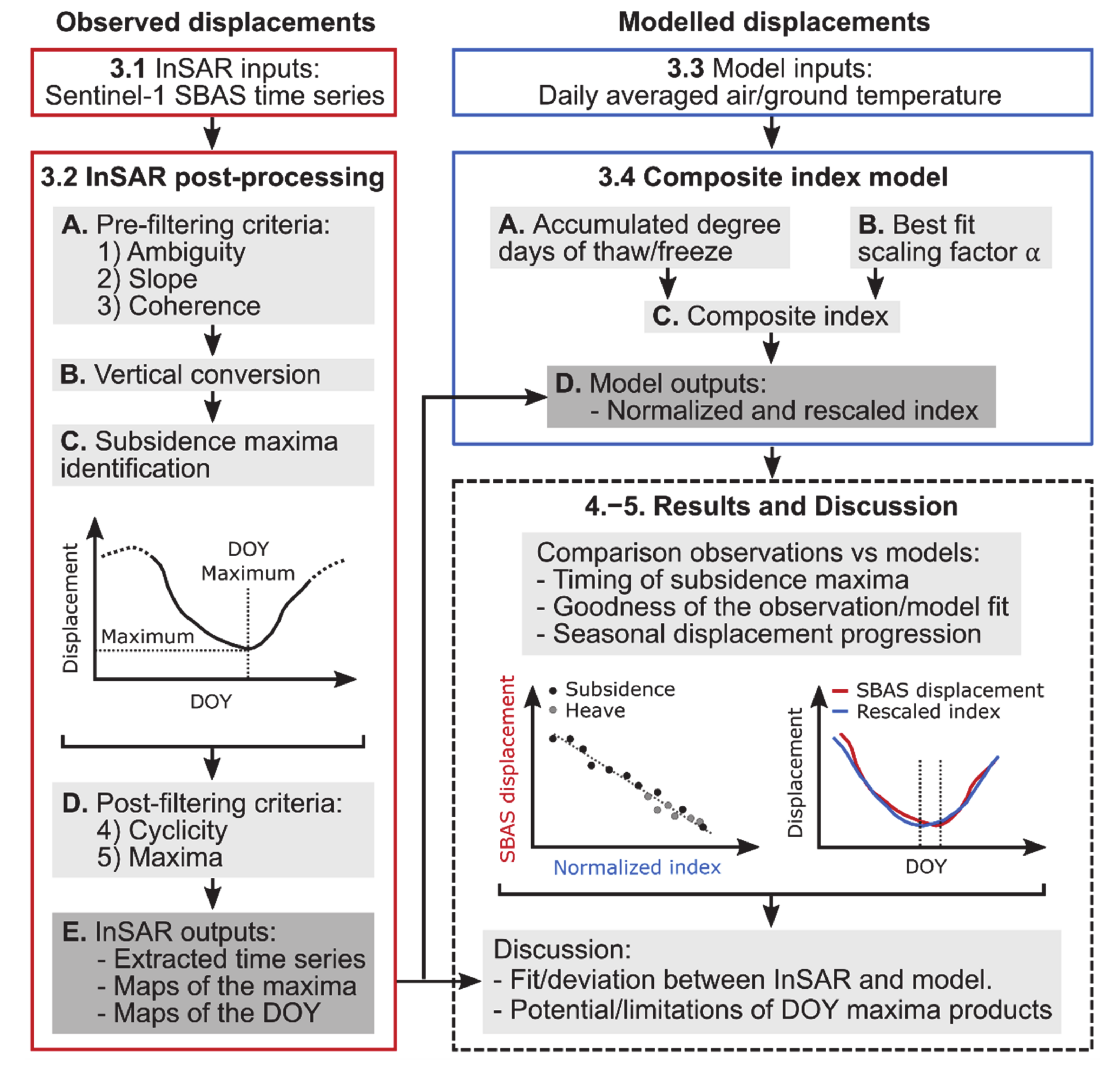
We propose a relatively simple workflow to generate high level products based on seasonal SBAS time series (inputs from Section 3.1). We applied conservative filters to remove unreliable and irrelevant information when focusing on the timing of the thaw subsidence maxima. The procedure follows five main steps to filter the SBAS results, convert the LOS values to vertical displacements, identify the maximal subsidence and extract the acquisition date of the maxima. These steps are illustrated in Figure 2 (observed displacements) and summarized hereafter:
A.
Pre-filtering of the initial SBAS results:
  • Criterion 1 “Ambiguity”: InSAR signal becomes aliased when the displacement gradient between adjacent pixels is higher than a quarter of the wavelength during the selected time interval. When using Sentinel-1 (5.6 cm wavelength), if the displacement is over 14 mm between the acquisitions used to build interferograms, there is a higher probability of spatial phase unwrapping error [69]. We therefore filtered out the results likely to be affected by a phase unwrapping error by filtering out pixels including a displacement gradient over 14 mm between successive acquisitions of the time series. If the displacement difference is over the ambiguity threshold, for example between the first acquisition (June 22) and the second (28 June), the pixel is discarded.
  • Criterion 2 “Slope angle”: Creep processes on slopes are likely to mask out the transition from subsidence to heave due to a gradual and continuous downslope displacement component. Based on a 20 m DEM [47], we computed the slope angle using ArcGIS (©ESRI). We discarded all pixels with slope angle >1.5°, to focus on flat areas (Supplement S4). Solifluction can occur on low-inclined surfaces, and has been reported on 2° slopes [77]. The conservative threshold of 1.5° was used to account for the relatively low DEM resolution, likely to underestimate local slope variabilities.
  • Criterion 3 “Coherence”: Decorrelation sources due to snow, ground moisture and vegetation may affect the quality of the displacement estimates [78]. We applied a secondary coherence thresholding more conservative than at the processing stage (Section 3.1). Pixels with mean coherence <0.55 based on the selected interferograms (Table 1; Supplement S1–S3) were discarded.
B.
Vertical conversion: InSAR measurements are intrinsically one-dimensional, along the oblique LOS (Table 1) and therefore provide ambiguous information in complex topography, especially if the movement orientation is spatially heterogeneous and/or temporally variable. As we focus here on flat areas, we can assume that all displacements occur vertically (subsidence and heave). Although some local areas (e.g., coastal areas affected by erosion) may slightly deviate from this general assumption, we expect that the dominant ground behaviour at the landscape scale is along the vertical. Therefore, we converted all results from LOS to vertical displacement using the following equation:
V disp = LOS disp cos I a
where Vdisp is the vertical displacement, LOSdisp is the LOS-projected displacement, and Ia is the incidence angle of the radar beam (Table 1). Vdisp documents a subsidence (positive value) or a heave (negative value), relatively to the first acquisition date.
C.
Subsidence maxima identification: For each time series, the maximal value was identified, and its corresponding Day of Year (DOY) was extracted. It should be noted that the DOY identification is based on the subsidence maximum only and does not take into account the entire pattern of the displacement progression, which may lead to erroneous value if the ground level flattens at the end of the thawing season.
D.
Post-filtering of the selected time series:
  • Criterion 4 “Cyclicity”: Pixels with DOY corresponding to the first or the last acquisition of the series (i.e., without any subsidence/heave pattern) were discarded, as they do not document a cyclic process. We assume that these pixels correspond to remaining low-inclined areas affected by downslope creep. In combination with Criterion 2 “Slope angle”, Criterion 4 is an additional way to ensure that we focus the analysis on flat areas dominated by vertical patterns.
  • Criterion 5 “Maxima”: All pixels with a maximal subsidence <10 mm were additionally discarded, as we assume that the transition between subsidence to heave in areas with low displacement amplitude is likely to be masked out by noise sources (e.g., atmospheric effects, bias due to snow or ground moisture). The temporal resolution of the DOY product is 6 days (12 days when there is one missing acquisition), corresponding the repeat-pass interval of the Sentinel-1 mission.
E.
InSAR outputs: For analysing the spatial distribution of the maximal subsidence, we used the results after the four first steps of filtering (Criteria 1−4), while all five criteria are used to map the DOY. For further comparison with the temperature-based model (Section 3.3 and Section 3.4), we focused on time series at three different scales (local, intermediate and regional) by:
  • Extracting the nearest pixels to the boreholes;
  • Averaging the series for the pixels within 1 km2 around the boreholes;
  • Averaging the pixels with a DOY of the subsidence maxima within the interquartile range of all results, as we assume that they are representative of the ground behaviour at the regional scale.
When averaging time series, the dispersion of the selected values can be represented by the standard deviation around the mean of the selected pixels for each acquisition date.

3.3. Air and Ground Surface Temperature

To interpret the InSAR measurements and evaluate the importance of the thermal control on the ground dynamics, we used daily averaged air temperature from three weather stations and ground surface temperature from three boreholes in all study areas (Table 2; Figure 1).

3.4. Composite Index Model of Seasonal Time Series

The SBAS time series were compared to a simple composite index model based on temperature (input from Section 3.3). The calculation of the composite index is explained in detail by Hu et al. [27]. The main steps of the procedure are schematically summarized in Figure 2 (modelled displacements) and can be described as follows:
A.
For a given time (t) in the season, the thawing (freezing) depth (Z) of the ground can be modelled using the Stefan equation [28,29], as follows:
Z t = 2 k n A t ρ θ L
where k is the thermal conductivity of soil (units: W·m−1·K−1), n is the n-factor ratio accounting for the offset between the air temperature and the ground surface temperature, influenced by the surface conditions (e.g., snow, vegetation) [80], and A(t) is the accumulated degree days of thawing or freezing (units: °C days). ρ is the soil bulk density (units: kg/m3), θ is the volumetric water content (units: m3/m3), and L is the specific latent heat of fusion for water (units: J/kg).
The phase change of water causes volume change of the ground medium within the thawed (frozen) layer. We assume that the 1D ground medium has homogenous and constant thermal properties and water content. All the water pores within the active layer are assumed to be affected by phase change, which causes a ~9% volume decrease and increase leading to subsidence and heave. Based on these assumptions and following the steps detailed in Hu et al. [27], we can express the subsidence (s) and heave (h) as a simple function of the variables A(t) and the time-invariant coefficients E:
s t = E T A T t   and   h t = E F A F t
where A(t) is the time-variant accumulated degree days of thawing (T) (units: °C days) or freezing (F) (units: °C days), based on the daily averaged air and ground surface temperatures from the sites introduced in Section 3.3EF and ET are time-invariant coefficients based on ground/water properties of the frozen (F) and thawed (T) ground (the soil bulk density, volumetric water content, water/ice density, latent heat of fusion for water, thermal conductivity, n-factors) [27].
B.
The two seasonal coefficients EF and ET can be related by a scaling factor α:
α = E F E T = k F n F k T n T
Where kF and kT are the thermal conductivities of the frozen (F) and thawed (T) ground and nF and nT are the n-factors nF and nT as described in Equation (2).
The scaling factor applied by Hu et al. [27] is 1.44 based on the ground properties of the Utqiaġvik site (Anchorage, AK, USA), and using air temperature series for the calculation of the composite index. In our study, the k and n coefficients remain undefined, due to variable and partly unknown ground properties in the study areas. We therefore focused on their relative difference (ratio between frozen and thawed ground) represented by the scaling factor α. When using ground surface temperature, the n-factors are 1, so α reduces to k F k T , i.e., the difference of thermal responses between thawed and frozen ground. We tested and compared the results using five α values (1, 1.2, 1.4, 1.6 and 1.8).
C.
Based on Equations (3) and (4), the composite index Ic can be expressed as:
I c t = A T t α A F t
We set the composite index to be zero until the start of the thawing season. The initiation of the calculation starts when the first daily averaged air and ground surface temperatures above 0 °C are recorded at the weather stations or in the boreholes.
D.
Because we are only interested in characterizing the temporal pattern of ground displacements, we normalized the composite index with its maximum value and rescaled it by multiplying the index by the maximal value of the SBAS displacement time series:
d t = d s I ¯ c t
where d(t) is the rescaled composite index, directly comparable with the observed displacement (Section 3.2), ds is the maximum seasonal subsidence based on the SBAS time series (units: mm) and I ¯ c is the composite index (Equation (5)) normalized with its maximum value.
The comparisons between the SBAS time series and the model (normalized and rescaled composite index) consisted of:
  • Comparing the timing of the transition between the subsidence and the heave from the observations and the thawing and freezing periods from the models;
  • Evaluating the goodness of the fit between the observations and the models by documenting the proportion of the variance of the seasonal SBAS displacements that is explained by the normalized index (R2);
  • Analysing the temporal variations of the entire observed displacement time series with respect to the rescaled composite index;
  • Discussing the results’ differences when using air or ground surface temperature, as well as single pixels closest to the boreholes, 1-km2 or regional averaged displacement time series.
We finally interpreted the fit/deviation between the observation and the model by discussing the limitations of the SBAS products and the validity/invalidity of the assumptions behind the simplified composite index model. The findings were related to the results from Section 3.2 to discuss the potential of DOY maxima products to document the cyclic dynamics of the active layer in permafrost landscapes.

4. Results

4.1. Thaw Subsidence Maxima

The final SBAS results (Section 3.2) are presented on maps showing the distribution of the subsidence maxima and their corresponding DOY (Figure 3, Figure 4 and Figure 5). The five criteria used for filtering significantly reduce the exploitable observations to 3–5% of the initially documented pixels (Supplement S5) but still provide a good coverage in the flat areas, mostly in the valley bottoms in ADV, and in the strandflat areas in KAP and NYA, with total pixel numbers of 14,547 in ADV, 21,198 in KAP and 6021 in NYA. The observed patterns are described by analysing the results at the landscape scale, as well as within selected km2 areas around the three boreholes and over landforms experiencing a behaviour that deviates from the regional trend. Orthophoto imagery of the corresponding locations can be found in supporting material (Supplement S6).
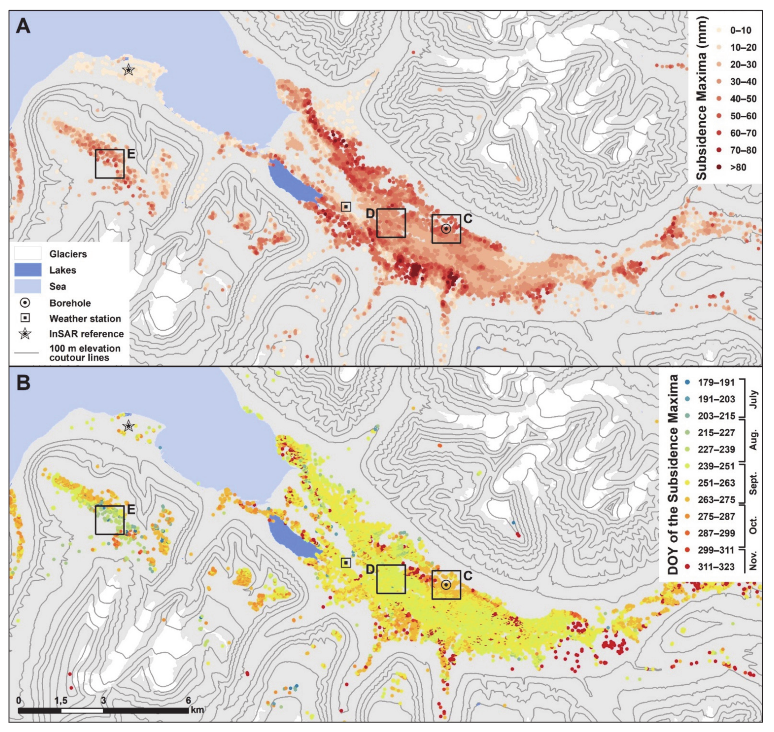
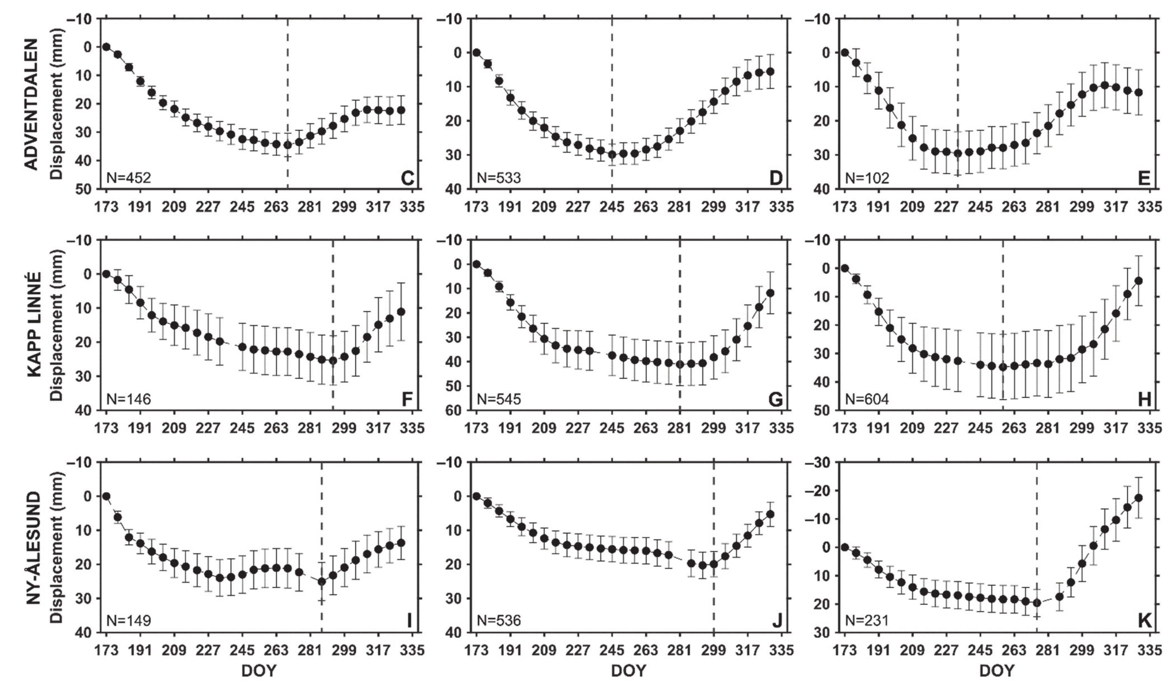
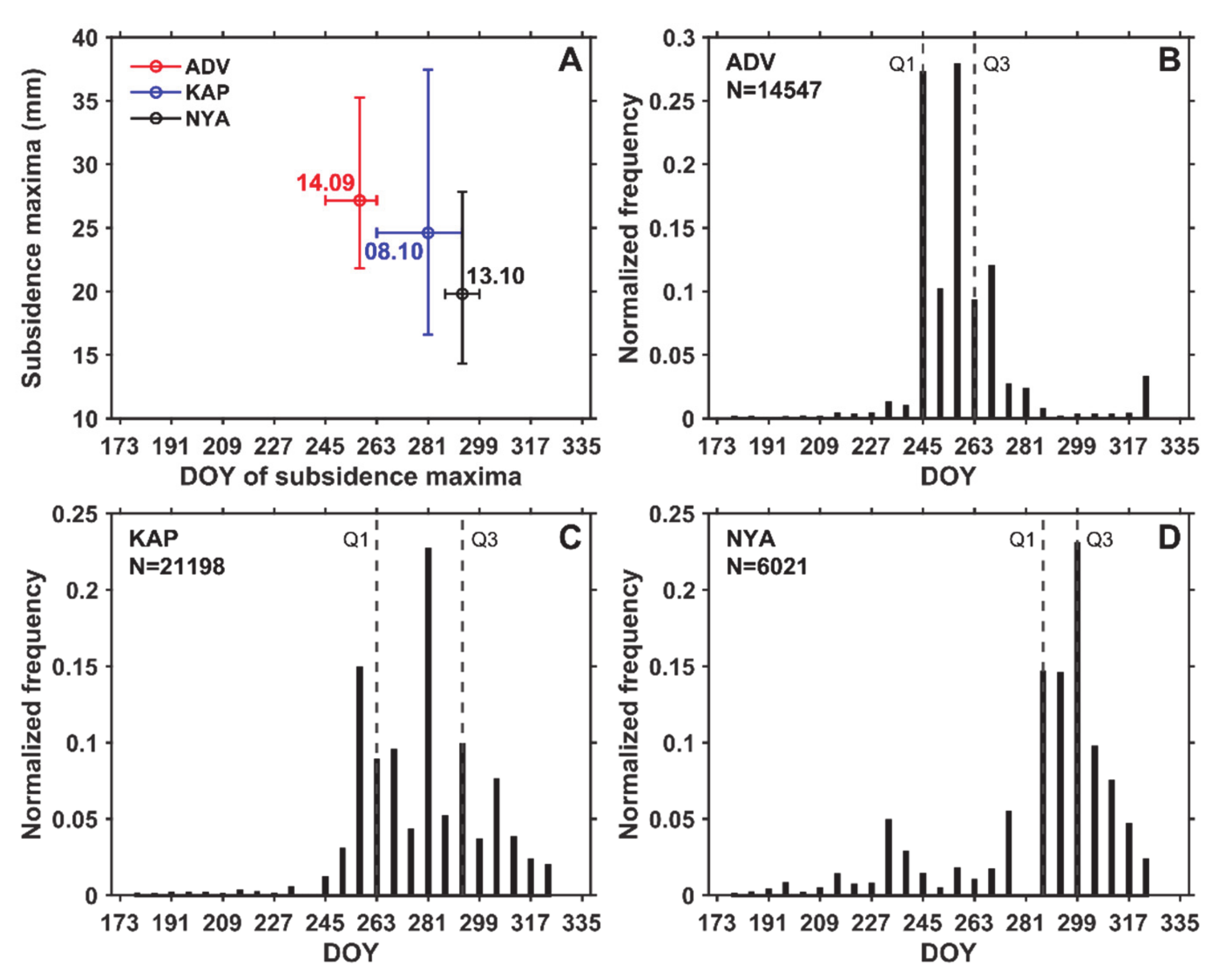
In ADV, displacements occurring between June 22 and the day of the subsidence maxima are mostly over 20 mm (Figure 3A). The displacement distribution is geomorphologically-controlled [21]. Large displacements are detected on landforms assumed to have high water content and composed of fine-grained frost-susceptible sediments. Greatest subsidence up to approximately 100 mm are found in the outer part of alluvial fans and in the eolian terraces surrounding the ADV braided river. The timing of the subsidence maxima is quite homogenous in the valley bottom (Figure 3B), with values between 251 and 269 (mid–late September). The maxima are identified later on the valley sides, e.g., where the borehole is located (Figure 3B, area C; Figure 6C), suggesting different ground behaviour between the terraces (Supplement S6C) and the fluvial riverbed (Supplement S6D). Most ADV time series show a clear cyclic displacement pattern, with a distinct and quick transition between subsidence and heave that allows for a mostly unambiguous extraction of the DOY maxima (Figure 6C,D). The subsidence maxima are identified earlier on the SW blockfield plateau (Figure 3B, area E; Figure 6E), suggesting earlier freeze-back due to higher elevations (400–500 m a.s.l). The end of the time series in November is often affected by a stabilization or lowering effect (Figure 6C,E). This presumed artefact, further discussed in Section 5.1, especially affects some alluvial fans in the inner part of the valley (eastern side in Figure 3B) where outliers with late DOY maxima are identified.
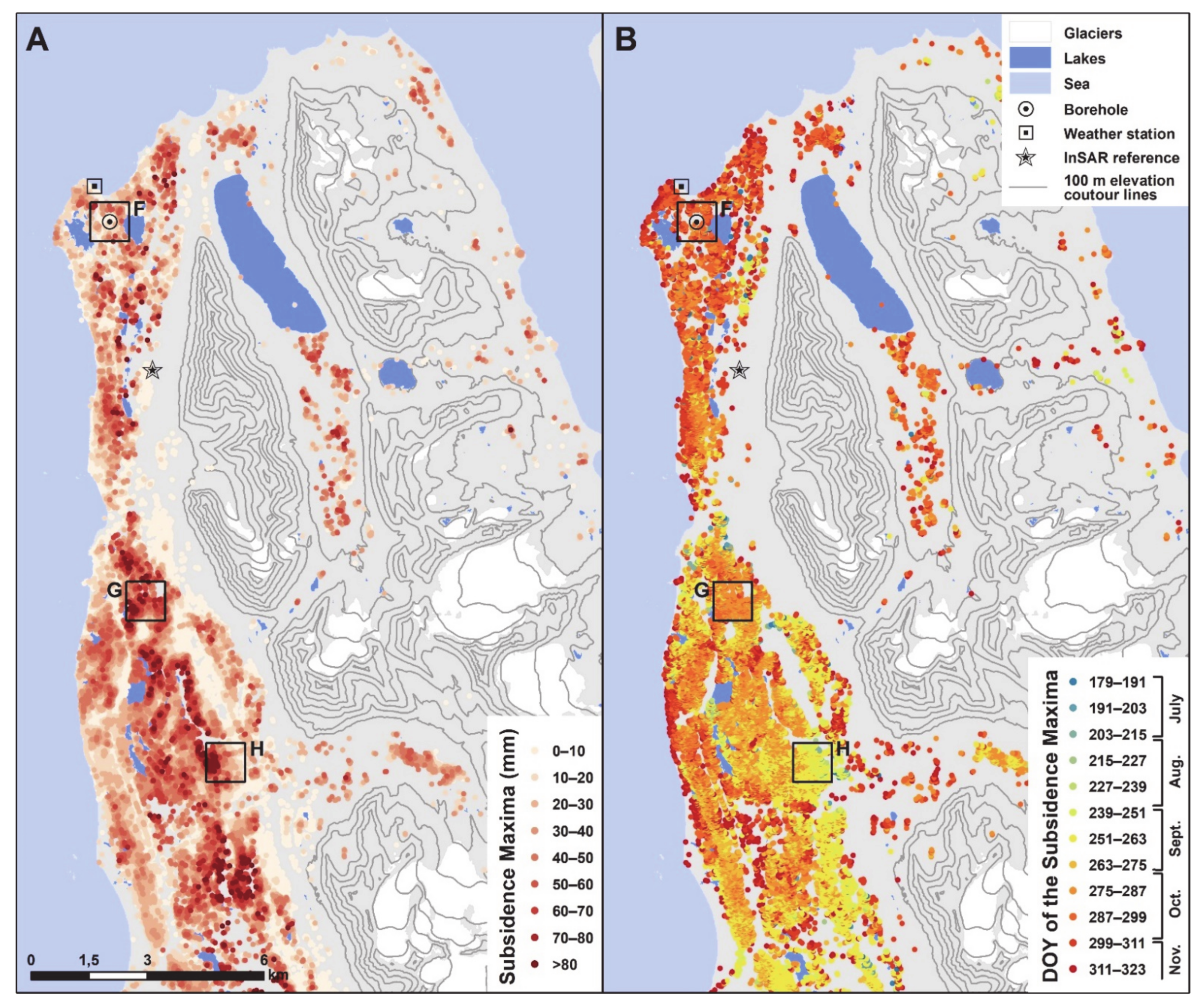
In KAP, the variability of the subsidence maxima matches the complexity of the landform assemblage in the area (Figure 4A), especially in the northern part (Supplement S6, area F). Low subsidence values (typically lower than 20 mm) are detected in areas composed of exposed bedrock or coarse-grained beach ridges, but maxima up to 120 mm are found in organic-rich and fine-grained sediments in beach ridge depressions. A spatial gradation with earlier DOY along the eastern slope compared to the coastal part highlights the impact of the maritime influence within the area (Figure 4B). The timing of the subsidence maxima is mostly homogenous in the northern part, e.g., where the borehole is located (Figure 4B, area F). The subsidence maxima occur considerably later than in ADV (287 to 305, i.e., in mid–late October). The transition between subsidence and heave is clear on series from the northern part (Figure 4B, area F; Figure 6F) but becomes more ambiguous towards the South, where earlier DOY are detected (Figure 4B, areas G–H; Figure 6G,H). The flattening of the displacement curves in mid–late summer shows that the ground level stabilizes for a long period (Figure 6G,H). The different behaviour observed on the beach ridges in the southeastern part of the strandflat may indicate specific ground conditions at the mouth of the Orustdalen valley (Figure 3B, area H). This is further discussed in Section 5.1.
In NYA, the documented surfaces are mostly composed of coarse beach and diamict deposits. The relatively little frost-susceptibility of the material leads to subsidence values generally lower than for the two other study areas, with maxima mostly under 40 mm (Figure 5A). Maximal subsidence, up to 80 mm, are found primarily in the western part of the peninsula, in the alluvial deposits surrounding the Kvadehukelva riverbed. Beach ridge depressions on the strandflat show relatively homogenous DOY values with subsidence maxima occurring approximatively at the same time as in the KAP area (287 to 299, in mid-October) (Figure 5B, e.g., in area J).
The northwestern part of the strandflat has considerably earlier DOY (Figure 5B, area K) compared to the surroundings (Figure 5B, area J), suggesting a different ground behaviour in the exposed coastal part of the landscape. This area, in the outer part of alluvial fans, experiences rather stable surface position, with only minor subsidence through the documented summer period, followed by quick and large heaving when freeze-back occurs (Figure 5B, area K; Figure 6K). In the inner part of Kongsfjorden (NE in Figure 5), some altitudinal variations and geographical zonation are visible, with earlier DOY compared to the outer part of the peninsula. Around the borehole, a heave pattern is detected in late August to mid-September, prior to the main one starting in mid-October (Figure 6I). We further discuss the potential causes of this pattern in relation with the composite index model (Section 4.2 and Section 5.1).
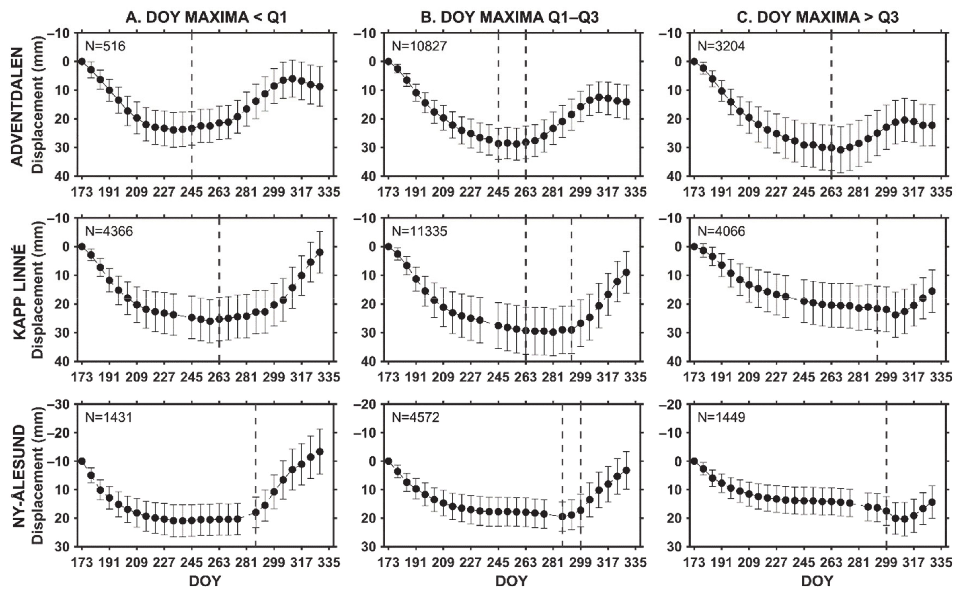
When comparing the results for the three areas, clear differences are identified (Figure 7). The median DOY of the subsidence maxima is earlier in ADV compared to KAP and NYA. Even considering the interquartile variability of the distribution, the values of ADV show no overlap with the two other areas (Figure 7A). KAP and NYA DOY maxima have overlapping distributions, but the detected subsidence values are lower in NYA (Figure 7A). Cyclic patterns are visible in all regionally averaged time series (Figure 8B), but the results highlight differences between the three study areas that are further discussed in Section 5.1. Time series with maxima below/over the first and third quartiles of the entire area (Figure 8A,C) exemplify the deviation from the most common pattern. Due to long thawing periods, the averaged time series in KAP and NYA show that the ground tends to remain stable during several months in mid–late summer (Figure 8), which likely affects the reliability of the automatic extraction of the subsidence maxima. This issue is further discussed in Section 5.2.

4.2. Composite Index Model of Seasonal Time Series

The daily averaged temperature series highlight differences between the air and ground surface temperatures measured at weather stations and in boreholes in each of the three study areas (Table 2). Short-term fluctuations are reduced in the time series from the boreholes (Figure 9A), mostly due to the insulating winter and spring effects of the snow and the thermal diffusivity of the upper soil layer. Especially at the beginning of the thawing season in ADV and NYA, a thermal offset and a time lag are observable between the two series. In NYA, the ground surface temperature during snow melting remained stable around 0 °C during three weeks after the air temperature became positive (Figure 9A). The start of the InSAR observation window on 22 June (measurement period, vertical black lines in Figure 9A) approximately fits the onset of ground thawing in the NYA borehole (20 June). In ADV and KAP boreholes, the ground thawing started on June 13 in ADV borehole and June 4 in KAP. This is 9 days (ADV) to 18 days (KAP) before the InSAR measurement period, which highlights the importance of interpreting the subsidence maxima values in a relative manner, due to the underestimation of the total seasonal subsidence.
The composite index was calculated based on air and ground temperature data from the three weather stations and boreholes (Section 3.3) (Supplements S7–S8). After testing five scaling factors α (Section 3.4), the results showing the best fit between the observed and modelled time series have been selected (Supplements S9–S10). At the regional scale, the pixels with a DOY of the subsidence maxima within the interquartile range of all series (Figure 8B) are compared with the composite index. The results show that for all study areas, the composite index models based on ground surface temperature from the boreholes provide a better fit with the observed subsidence and heave than when using air temperature as input (Figure 9B and Supplement S11). This can be explained by the lag between air and ground temperature, especially at the thaw onset. For further analysis, we therefore used ground surface temperature as input to the models at all scales and for all areas.
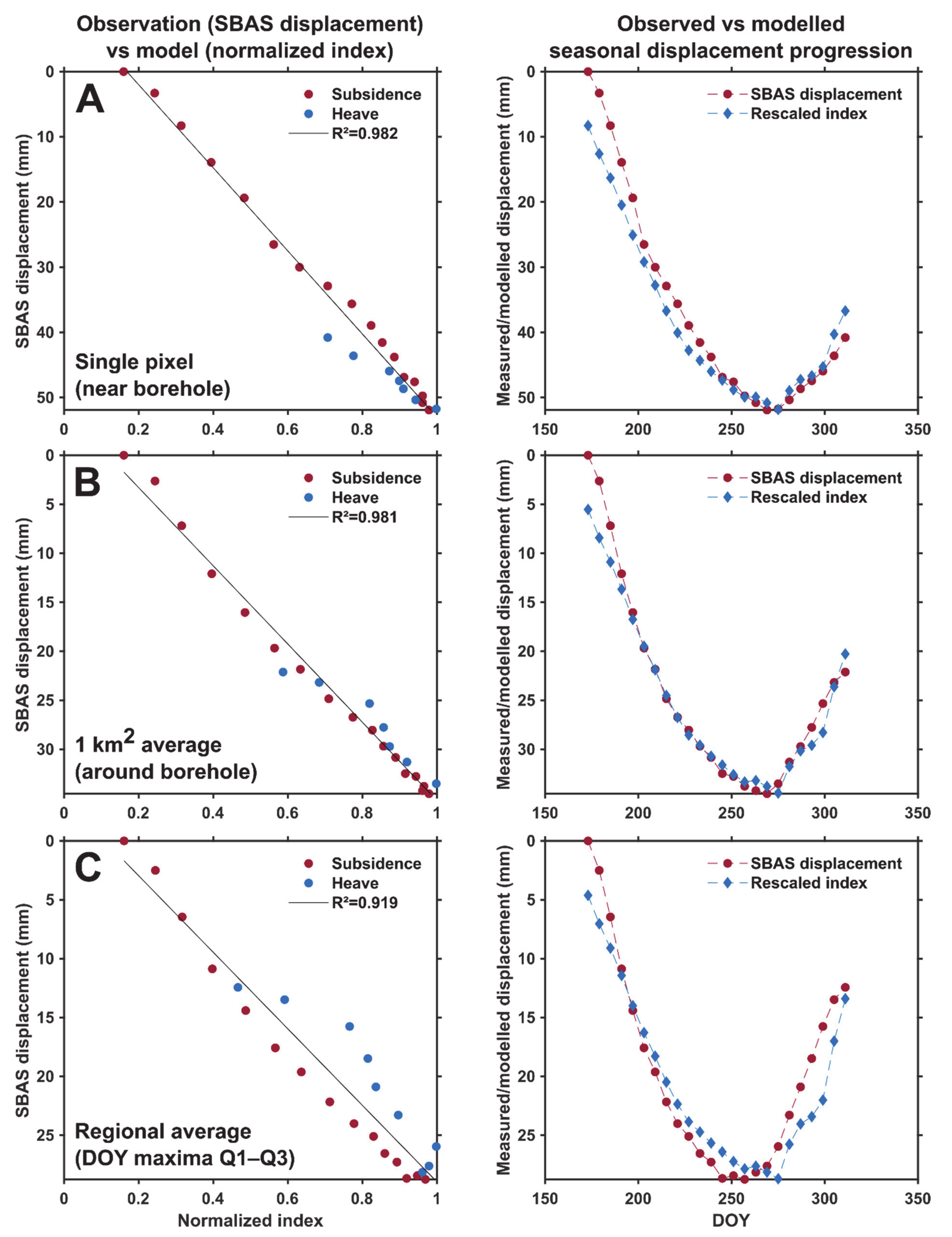
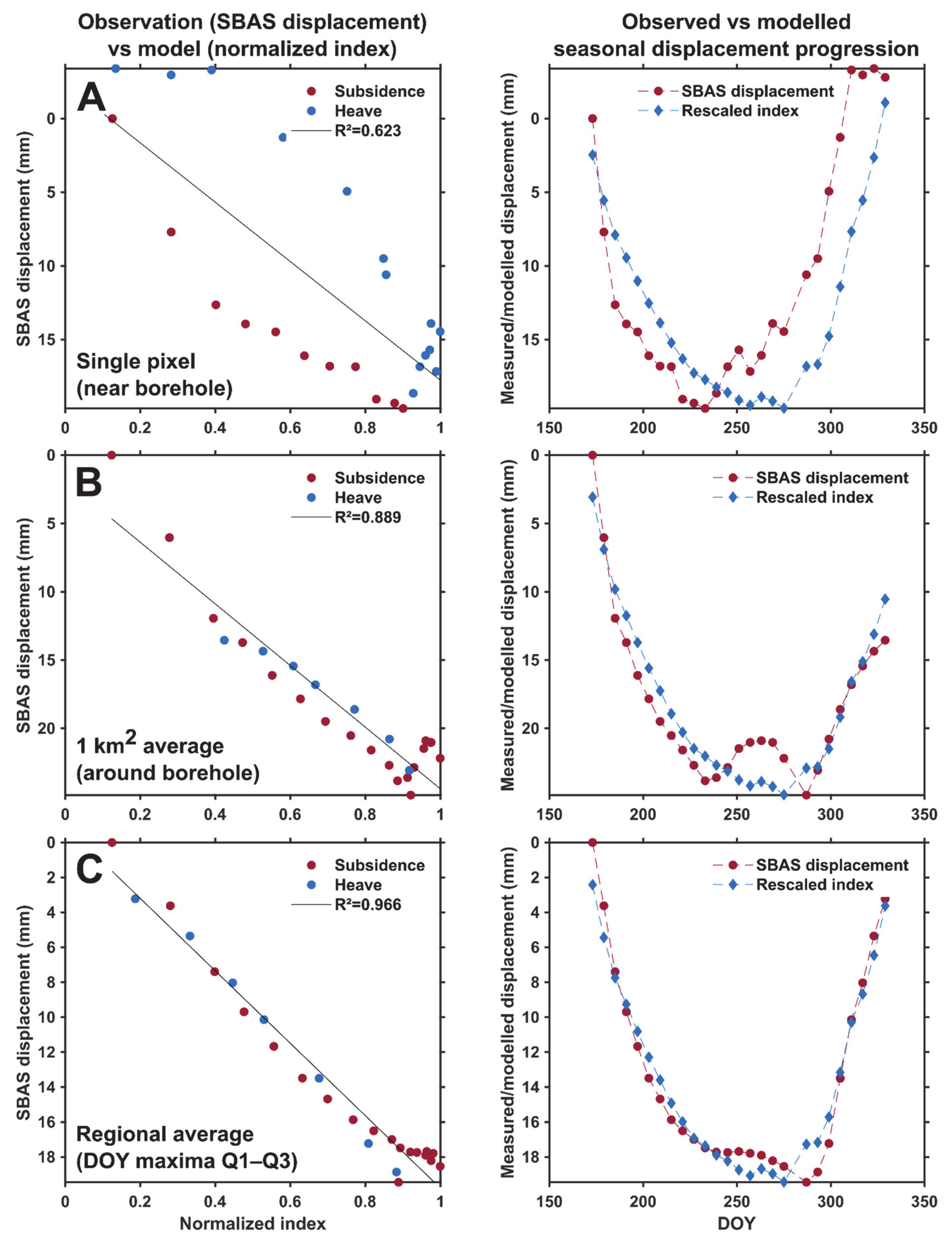
In ADV, at the borehole location, both the timing of the transition from subsidence to heave and the whole displacement progression is well represented by the composite index (Figure 10A). Similarly, the match is good for the intermediate scale (km2 average) (Figure 10B). At the regional average, the general shape of the curve is well represented by the model, but the measurements are shifted compared to the modelled displacements, especially during heaving (Figure 10C). The observed subsidence maxima and the following heave occur earlier than the model. This shows that the borehole is located in an area that deviates from the interquartile regional averaged series, which is also visible when examining the spatial distribution of the DOY of the subsidence maxima (Figure 3B).
In KAP, the pixel closest to the borehole shows noisy patterns, especially at the beginning and the end of the documented period (Figure 11A). The progression of the displacements is not well represented by the model, but the timing of the transition matches the composite index. The km2 average allows for removing some variability and improves the fit between measurements and the model (Figure 11B, left), although the whole displacement progression still appears to be controlled by other factors than temperature only (Figure 11B, right). The regional average reduces short-term variability, especially during late subsidence, which is well represented by the model. However, as for ADV, the timing of the transition is slightly shifted (Figure 11C). The natural variability in this wide and geomorphologically heterogeneous area does not allow for representing averaged regional displacements based on temperature from one single borehole site located on a dry beach ridge (Supplement S6F).
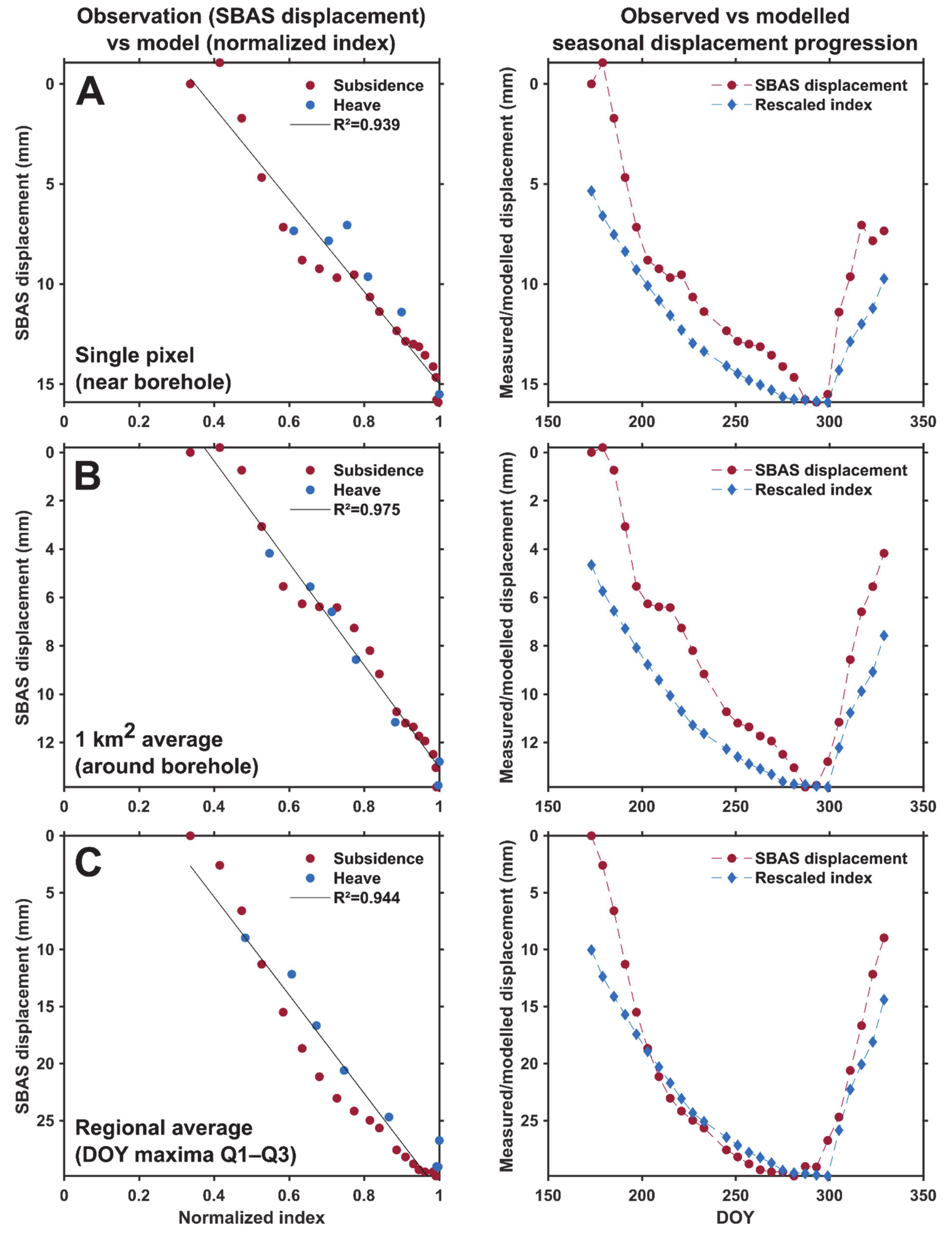
In NYA, the comparison between the composite index and the InSAR time series closest to the borehole shows a clear shift (earlier for the InSAR series) and a low R2, showing that the processes occurring at this specific location can not only be explained by a simple temperature-based model (Figure 12A). With a km2 average, the InSAR series highlight an ambiguous pattern, with a small heave occurring prior to the main one (Figure 12B). It approximately occurs when the temperature drops and fluctuates around 0 °C for about a week (Figure 9A). The pattern is only visible in the highest part of the landscape (Figure 5I and Figure 6I). Figure 12 generally highlights a poor correspondence between the measurements and the model for the acquisition dates close to the subsidence maxima. Nevertheless, when averaging series at a regional scale, the match between the observation and the model increases considerably (Figure 12C).
The comparison of the three areas leads to contrasting conclusions. In ADV, the time series have a clear cyclic pattern that is well represented by the model at local and km2 scales. At larger scale, the fit between the observation and the model decreases. The area where the borehole is located appears to be not representative of the regional behaviour dominated by earlier DOY in the fluvial sediments of the brained river plain. In KAP, the km2 average provides a better fit with the model than a single pixel. The timing of the subsidence-to-heave transition generally fits the temperature records, but the whole displacement progression is not fully explained by the model. At the regional scale, inversely, the displacement progression is well represented by the model, but the subsidence-to-heave transition is somewhat shifted. In NYA, the observation at local scale is not explained by the model. However, by averaging the series within a km2 or at regional scale, the match improves considerably. The differences between the three areas are further discussed in Section 5.1 and used to identify the advantages and limitations of the proposed method and applied model in Section 5.2.

5. Discussion

5.1. Seasonal Displacement Patterns

The documented subsidence maxima in the three areas of central and western Spitsbergen (mostly within 15–35 mm, with maximum up to 120 mm) are in the commonly reported ranges of seasonal cyclic displacements in continuous permafrost areas [13,25,27] and generally agree with other observations made in Svalbard [81,82,83]. However, it is important to consider that the applied InSAR measurement period is underestimating the total subsidence, especially in areas where the thaw onset starts significantly earlier than the InSAR observation window (Figure 10A). Based on the thaw depth progression from in-situ probing in the University Centre in Svalbard Circumpolar Active Layer Monitoring network grid (UNISCALM) [42,45], early summer is indeed known to experience a quick thawing rate, which may induce an undocumented subsidence before the InSAR measurement period if ground ice melts in the upper part of the active layer. The underestimation of the subsidence is likely even greater in the warmer KAP area. The NYA area shows nevertheless clearly lower subsidence values than ADV and KAP (Figure 7A), which is most likely caused by a generally thinner and more coarse-grained sediment cover [62]. The large variability of the displacement values within and between the study areas is assumed to be controlled by the active layer thickness and the ground conditions (ice type/content, frost-susceptibility of the material). The relationship between landform types and InSAR displacement rates has been discussed in a former Svalbard study [21] and by several authors in other continuous permafrost environments of the Northern Hemisphere, such as Siberia, Alaska and Canada [16,20,84,85].
The InSAR time series after filtering highlight clear cyclic patterns, but the timing of the displacement progression varies between the three study areas. Distinct transitions from subsidence to heave are found in ADV, while more ambiguous patterns are observed in parts of the KAP and NYA areas. The extracted DOY of the subsidence maxima vary between the three regions. The results especially highlight a clear difference between the KAP and NYA areas located on the West coast and ADV in central Spitsbergen. This emphasizes the maritime influence of the warm sea in KAP and NYA, compared to ADV, one of the most continental parts of Svalbard [40,54].
In ADV, the mean annual air temperature was −2.8 °C in 2017 [79]. Ground surface temperature at borehole location showed relatively cold conditions with only 356 °C days of thaw in 2017 (Supplement S8). The area is characterized by early subsidence maxima (DOY median values: September 14) (Figure 7A). At the location of the borehole, the maximum occurs later (September 26), which approximately concurs with the ground surface temperature series (Figure 10A). The difference between the fine-grained terraces and the coarse sediments surrounding the riverbed in the valley bottom, visible on DOY maxima maps (Figure 3B) as well as on the entire time series (Figure 6C), highlight a contrasting response of the ground to temperature fluctuations. It suggests that the ground reacts quickly to the first recorded negative temperature in coarse fluvial sediments, while the process is delayed on the loess terraces. The different behaviour at the location of the borehole, compared to most of the valley bottom, is also documented by in-situ measurements. At the UNISCALM site, the thaw onset typically occurs between late May and early June [42,45], while thawing is delayed at the location of the selected borehole (first positive temperature at ground surface on 13 June 2017) (Figure 9, Supplement S8). InSAR time series with subsidence maxima above the first third quartile (Figure 8C) appear to be affected by a systematic bias at the end of the documented period. No clear source has been identified, but we hypothesize that the stabilization or lowering effect at the end of time series (November) may be caused by complex scattering processes due to snow or surface icing [78]. Time series with maxima below the first quartile of the entire area (Figure 8A) are mostly located in elevated parts of the landscape (blockfield plateaus) and suggest a natural earlier freezing onset due to colder, drier and/or well-drained conditions. Although less obvious, similar gradients seem to affect the two other areas. In KAP, later subsidence maxima are detected in the western part, most exposed to the maritime influence, compared to the more protected eastern part of the study area (Figure 4B). In NYA, early subsidence maxima are detected in the NE part (Kongsfjord interior), compared to the exposed strandflat in the outer part of the peninsula (Figure 5B).
In KAP, a large heterogeneity is highlighted both in terms of maximal subsidence values and timing of displacement progression (Figure 4 and Figure 6F–H), which is assumed to illustrate the complexity of the landform assemblage in the wide area [59,60]. KAP has a warmer climate compared to ADV, with a mean annual air temperature of −1.5 °C in 2017 [79]. The study area experiences early ground thawing and late freezing leading to 674 °C days of thaw based on ground surface temperature (Supplement S8). The area is characterized by later subsidence maxima (DOY median value: October 8) (Figure 7A), compared to ADV (DOY median values: September 14). At the location of the KAP borehole, the detected DOY (20 October) approximatively fits the end of thawing season recorded by the temperature sensors (Figure 11A). Especially in the southern part (Figure 6G,H), the ground level stabilizes for a long period in mid–late summer, likely due to low ice content in the lower active layer. Noise sources are more likely to impact the displacement trends in periods with very few variations of ground level, which may induce uncertainties in the automatic identification of the subsidence maxima. KAP time series with DOY of the subsidence maxima above the first third quartile (Figure 8C) appear to be affected by late summer subsidence that may indicate the thaw front reached the ice-rich top of the permafrost. A similar pattern is also visible in the NYA study area.
NYA had a mean annual air temperature of −2.9 °C in 2017 [79]. The ground surface temperature from the borehole shows 570 °C days of thaw in 2017 (Supplement S8), which corresponds to an intermediate case compared to ADV and KAP. Observations in NYA generally highlight more ambiguous results, assumed to be caused by two main elements. First, snowfall occurred in early October 2017, which led to large decorrelation in all interferograms connected to the 8 October Sentinel-1 acquisition. This data gap reduced the temporal resolution to 12 days in a critical period for documenting the detection of the subsidence maxima. Second, the air and ground surface temperature series show that a long period is affected by oscillations close to the freezing point from September until the clear decrease of temperatures in late October (Figure 9A). These fluctuations are recorded both on time series from the weather station and the borehole, but the stabilization close to 0 °C is especially visible on ground temperature data (Figure 10A). A slight but consistent summer heave is detected at the end of the thawing season in the time series surrounding the NYA borehole (Figure 12B). A short period in mid-September shows a drop of both air and ground surface temperature close to or under 0 °C (Figure 9A, Supplement S8), but the AL ground thermal data [66] do not show any significant refreezing able to fully explain the displacement pattern. One possible explanation is that the km2 average is dominated by an upward effect from surficial icing occurring around the riverbed, in the meltwater plain surrounding the hill where the borehole is located. The well-developed active layer may also have favoured water migration towards the frozen layer leading to ice formation at the permafrost table [86].
In general, the misfit between the InSAR observations and the model at the location of the borehole (Figure 12A) suggests that a simple model only based on surface temperature is not able to represent all mechanisms occurring in this area. Similarly, an early ground stabilization and heave pattern is detected in the western part of the Brøggerhalvøya peninsula (Figure 5B, area K, Figure 6K). This exposed coast was likely snow-free long before the start of the InSAR series (22 June), which possibly led to some subsidence prior to the documented period. The ambiguous pattern at this location may also suggest complex hydrological processes, variable water flux within the active layer and potential late summer ice segregation at the top of the permafrost [30,31,32]. Similar processes may also explain the early pattern detected in the southern part of KAP (Figure 6F and Figure 8A). Located at the mouth of the Orustdalen valley occupied by large glacial systems in its upper part, this area may be subject to large water outflow variations.

5.2. InSAR Products as Proxy of the Active Layer Thermal Regime

The study has been designed with the general objective to develop InSAR products able to infer the active layer thermal regime in flat permafrost areas. This is based on the assumptions that (1) at the seasonal timescale, the subsidence and heave temporal patterns are mostly controlled by the AL thermal variations; (2) the subsidence maximum can be used as a proxy of the AL thaw maximum. The comparisons between the InSAR displacements and the composite index models show that the observations are generally well represented by the models, even if exclusively based on accumulated degree days of thawing and freezing, which confirms that the seasonal changes of surface level are mostly determined by the ground thermal conditions. Models based on ground surface temperature performed better than when using air temperature, which concurs with several studies documenting the thermal offset and time lag between the atmosphere and the ground, in particular due to snow cover [87,88,89]. At the local scale in ADV (Figure 10A) and for km or regional averages in KAP and NYA (Figure 11B,C and Figure 12B,C), the temperature-based model well represents the observed displacement pattern (Figure 13, scenario 1), and the acquisition dates of the maximal InSAR displacement generally match the timing of transition between the thawing and freezing periods (Figure 13, scenario A). In these cases, the results show that the documented subsidence maxima can be appropriately used as a proxy of the end of the AL thawing period.
However, we also highlight different inferior scenarios when (1) the model fails to provide similar displacement series as InSAR due to oversimplistic assumptions, e.g., excluding the impact of variable water content, the water flux within the active layer and/or the potential late summer ice formation at the top of the permafrost (Figure 12, scenarios 2 and 3); (2) the extracted DOY of the subsidence maxima may not correspond to the end of the thawing period, due to ground level stabilization over long periods and short-term fluctuations in the time series (Figure 13, scenarios B and C). In certain cases, the model fails to explain the whole displacement progression but the timing of the transition between subsidence and heave fits with the temperature records (Figure 13, scenario 2). This is typically the case at the local scale in KAP (Figure 11A).
In other cases, the whole index is shifted compared to the measurements, such as in NYA (Figure 12A). Moreover, independently to the model validity, the extracted DOY may be erroneous. It typically occurs if the displacement time series has large variability due to summer heave or measurement noise (Figure 13B,C), and/or if the curve flattens due late summer ground stabilisation caused by low ice content in the lower AL (Figure 6F and Figure 7A). In these cases, the DOY may be detected earlier than the actual end of the thawing season. Discontinuous series can also lead to shifted DOY identification if the natural transition occurs around the date of a discarded acquisition, such as in NYA (Figure 12C). When considering several thousand pixels in hundreds of km2 areas, the major issue is to discriminate what causes the model to fail and/or the DOY extraction to misrepresent the targeted transition time.
The identified limitations highlight potential for further research to exploit InSAR time series and document the temporal dynamics of the active layer in permafrost areas. The developed products and applied model are based on simple assumptions and may require adjustments to be exploited systematically at a larger scale. We suggest that future developments can be achieved by considering the following elements:
  • InSAR processing: The InSAR procedure is currently based on a site-dependent selection of interferograms that include several manual steps (Section 3.1). The variability of the snow cover is the main challenge that can lead to spatially and temporally discontinuous coherent interferometric signals (such as in NYA). Applying automated adaptive filtering, possibly based on a combination of SAR backscatter, InSAR coherence and external meteorological information would be valuable to upscale the procedure, for example to the entire glacier-free land of the Svalbard archipelago. Instead of exploiting similar acquisitions in areas with variable climatic conditions, adaptive InSAR observation windows would allow for the selection of locally relevant periods, starting from the first snow-free scene after thaw onset, and thus avoiding an underestimation of the total seasonal subsidence values (such as in ADV and KAP, Figure 9A).
  • DOY extraction: To identify more robustly the timing of the transition between thawing and freezing seasons and solve the issue related to the late-summer flattening of the displacement curves visible in some time series (Figure 13, scenario C), more sophisticated procedures could be tested, for instance by fitting a polynomial function to the entire time series and/or by analysing the displacement gradients between acquisitions, in addition or instead of simply considering the maximal value of the InSAR time series. Scenarios where primary and secondary maxima are identified could also be valuable to further study the cases of summer heave patterns (Figure 13, scenario B).
  • Time series averaging: While single time series may be affected by errors or unrepresentative local phenomena (Figure 11A and Figure 12A), the results in KAP and NYA suggest that averaging reduces the noise level and dampens the effect of specific small-scale effects to focus on the main climate-controlled trends. Kilometric averaging may be favoured in future product development, to keep documenting spatial variability while providing more robust information about the general seasonal pattern. At this scale, InSAR processing could be performed with larger multi-looking factors to provide more robust phase statistics for each pixel. Kilometric averaged displacement time series can easily be compared and coupled with transient modelling of thermal conditions based on remotely sensed surface temperature at a similar resolution [11,90]. Comparing InSAR with modelled temperature would have the advantage of increasing the measurement density compared to weather stations and boreholes and could provide new insights on the causes of the spatial-temporal variability of the time series. Moreover, InSAR products could complement and potentially constrain the current permafrost models by indirectly documenting the variability of the ground ice content and the timing of active layer freeze/thaw at a fine resolution and a large scale.
  • Time series modelling: To further evaluate the factors controlling the seasonal progression of the displacements in permafrost regions, InSAR observations could be compared with modelled time series based on a variable set of parameters. The composite index model applied in this study is based on the Stefan equation, with simplistic assumptions regarding the ground properties that can explain that the model fails to represent the measurements in several cases (Figure 13, scenarios 2 and 3). As discussed by Gruber [30], one main issue is related to the assumption of constant water content and absence of liquid water in the frozen layer. The model also assumes that the heave is caused by the volumetric change of pore water turning into pore ice (in-situ water freezing). It does not consider the ice segregation (formation of ice lenses), which is known to be an important factor causing frost heave [5,32,91]. Other formulations using the Leybenzon equation, the Kudryavtsev’s or the Gold and Lachbruch’s models [1,29] could be implemented and compared with InSAR time series. Frost heave models taken into account ice lens formation [92] could also be used to further interpret the InSAR-based displacement patterns and their controls.
By implementing the previously listed suggestions, it may become possible to further interpret the spatio-temporal variability of the ground dynamics, and compare the results with geological and hydrological variables based on field mapping and in-situ measurements, following previously applied methodologies in similar environments [84,85]. Remote sensing products documenting the ground dynamics can be used to monitor the active layer in Svalbard and other polar regions. ALT is one of the two components of the permafrost ECV, which is mainly obtained by field probing or borehole measurements [6,45]. ALT is often based on measurements of the maximal thaw depth. When the field measurements are discontinuous, e.g., through biweekly/monthly/seasonal probing, selecting the right time to measure the thaw depth can be a challenge. Providing systematic regional remotely sensed information about the active layer dynamics with a six-day resolution would help field scientists to target the best time of their in-situ ALT measurements. Based on one single season (June–November 2017), our study primarily aimed to test the feasibility of applying a simple procedure to generate InSAR maps and time series designed for identifying the cyclic ground dynamics in permafrost regions. The results suggest that the strategy could be valuably integrated into future operational monitoring systems, to document the long-term evolution of the active layer at large scale. If generated systematically, for each season and at a larger scale, such datasets can also enhance the comparison with other remotely sensed environmental variables, such as vegetation phenology and snow cover time series [93,94]. These products could also be combined with top-of-permafrost excess ground ice maps, estimated from late-summer InSAR subsidence, as developed by Zwieback & Meyer [18].

6. Conclusions

The study first aimed to develop Sentinel-1 InSAR products documenting the spatial variability and timing of the seasonal thaw subsidence maxima in three regions of central and western Svalbard characterized by different geomorphological and climatic conditions. We show that the maximal subsidence and its timing vary between the three regions. The maxima occurred earlier in Adventdalen (mid-September) compared to Kapp Linné and Ny-Ålesund (early–mid October), both located along the warmer west coast. The identified maximal subsidence values vary within and between the regions and are assumed to depend on the active layer thickness, water/ice content and frost-susceptibility of the ground material. The results show clear cyclic patterns in all study areas and at the three considered scales (single pixels, km2 and regional averages). The variable displacement progression is assumed to represent the natural variability of the climatic parameters and ground conditions. Some time series have long periods characterized by ground stabilization in late summer, which makes the identification of the subsidence maxima uncertain. Ambiguous displacement patterns are observed in Ny-Ålesund, including a secondary heave in a relatively cold period in late summer.
Then, we compared the displacement time series with a composite index based on air and ground surface temperature and evaluated how a simple model can explain the progression of subsidence and heave patterns in the study areas. Comparisons between the InSAR observations and the model show that the composite index based on ground surface temperature from the boreholes performs better than the air temperature index due to thermal offset and time lag between the atmosphere and the ground, especially at the thaw onset. In Adventdalen, the model explains well the displacement progression extracted at the location of the borehole. In Kapp Linné and in Ny-Ålesund, larger deviations are found at pixel-scale, likely due to site-specific factors and complex hydrological effects occurring in the active layer. However, km or regional averaging allows for improving the match between the models and measurements, which suggests that at this larger scale, the displacement patterns are primarily controlled by the thermal response of the active layer to atmospheric forcing.
Finally, we discussed the potential and limitations of using the timing of the maximal subsidence as a proxy for the end of the thawing season and suggested ideas for the development of alternative InSAR products in polar areas characterized by cyclic patterns. The findings show that dense and frequent InSAR measurements of thaw subsidence and frost heave have the potential to upscale the documentation of the active layer thermal regime over wide permafrost areas. Limitations related to the proposed InSAR products and the simple assumptions behind the composite index model are discussed and identify potentials for follow-up research to couple InSAR with modelling and design future operational remote sensing strategies in Svalbard.

Supplementary Materials

The following supplements are available online at https://www.mdpi.com/article/10.3390/rs13152977/s1: Supplements S1–S3: Baseline plots of the Sentinel-1 interferometric pairs. Supplement S4: Slope map and mask for the filtering criterion 2 “Slope angle”. Figure S5: Percent of documented pixels after the five steps of filtering. Supplement S6: Orthophoto imagery of the 1-km2 areas. Supplements S7 and S8: Air and ground temperature, calculated ADDT/ADDF and composite index. Supplements S9–S10: Coefficient of determination R2 or proportion of the variance of the InSAR displacements that is explained by the composite index, based on air and ground temperature, after having tested five scaling factors α. Supplement S11: Measured and modelled displacements based on air temperature.

Author Contributions

Conceptualization: L.R. and L.L.; methodology and software: L.R., L.L., Y.L. and T.R.L.; formal analysis, investigation and visualization: L.R.; data curation: L.R., S.M.S., H.H.C. and T.R.L.; project funding and administration: L.R. and T.R.L.; writing—original draft preparation: L.R.; writing—review and editing: L.L., H.H.C., S.M.S., T.R.L. and Y.L. All authors have read and agreed to the published version of the manuscript.

Funding

The study is part of Rouyet’s Ph.D. research project FrostInSAR (2017–2021) funded by the Space Research Programme of the Research Council of Norway (grant 263005). The development of the GSAR processing chain and previous research applying InSAR in the Norwegian periglacial environment have been supported by the Norwegian Space Centre, the European Space Agency and the Research Council of Norway. L. Liu was supported by the Hong Kong Research Grants Council (CUHK14305618).

Data Availability Statement

The filtered InSAR time series, the subsidence maxima and corresponding DOY are available in Zenodo: https://doi.org/10.5281/zenodo.4775398 (created on 20 May 2021). Additional data sources used in this study are listed in the references, included in the figures and tables, or in the supporting information associated with this publication.

Acknowledgments

We acknowledge the five judges from the editorial board of SIOS’s special issue who awarded a related presentation at the SIOS’s online conference (4–5 June 2020) at the origin of the research presented in the current manuscript. We acknowledge the valuable comments of two anonymous reviewers and the academic editor. We thank the helpful support of the managing editor Aurora Wang.

Conflicts of Interest

The authors declare no conflict of interest. The funders had no role in the design of the study; in the collection, analyses, or interpretation of data; in the writing of the manuscript, or in the decision to publish the results.

References

  1. French, H.M. The Periglacial Environment, 3rd ed.; John Wiley & Sons: Hoboken, NJ, USA, 2007. [Google Scholar]
  2. Schuur, E.A.; McGuire, A.D.; Schädel, C.; Grosse, G.; Harden, J.W.; Hayes, D.J.; Hugelius, G.; Koven, C.D.; Kuhry, P.; Lawrence, D.M. Climate change and the permafrost carbon feedback. Nature 2015, 520, 171–179. [Google Scholar] [CrossRef]
  3. Hjort, J.; Karjalainen, O.; Aalto, J.; Westermann, S.; Romanovsky, V.E.; Nelson, F.E.; Etzelmüller, B.; Luoto, M. Degrading permafrost puts arctic infrastructure at risk by mid-century. Nat. Commun. 2018, 9, 1–9. [Google Scholar] [CrossRef]
  4. Jorgenson, M.T.; Racine, C.H.; Walters, J.C.; Osterkamp, T.E. Permafrost degradation and ecological changes associated with a warming climate in Central Alaska. Clim. Chang. 2001, 48, 551–579. [Google Scholar] [CrossRef]
  5. Rempel, A.W. Formation of ice lenses and frost heave. J. Geophys. Res. Earth Surf. 2007, 112, F02S21. [Google Scholar] [CrossRef]
  6. Bonnaventure, P.P.; Lamoureux, S.F. The active layer: A conceptual review of monitoring, modelling techniques and changes in a warming climate. Prog. Phys. Geogr. 2013, 37, 352–376. [Google Scholar] [CrossRef]
  7. Biskaborn, B.K.; Smith, S.L.; Noetzli, J.; Matthes, H.; Vieira, G.; Streletskiy, D.A.; Schoeneich, P.; Romanovsky, V.E.; Lewkowicz, A.G.; Abramov, A. Permafrost is warming at a global scale. Nat. Commun. 2019, 10, 1–11. [Google Scholar] [CrossRef] [PubMed] [Green Version]
  8. Meredith, M.; Sommerkorn, M.; Cassotta, S.; Derksen, C.; Ekaykin, A.; Hollowed, A.; Kofinas, G.; Mackintosh, A.; Melbourne-Thomas, J.; Muelbert, M.M.C. Chapter 3. Polar regions. In IPCC Special Report on the Ocean and Cryosphere in a Changing Climate; The Intergovernmental Panel on Climate Change: Geneva, Switzerland, 2019. [Google Scholar]
  9. Nitze, I.; Grosse, G.; Jones, B.M.; Romanovsky, V.E.; Boike, J. Remote sensing quantifies widespread abundance of permafrost region disturbances across the Arctic and Subarctic. Nat. Commun. 2018, 9, 1–11. [Google Scholar] [CrossRef] [PubMed]
  10. Zhang, T.; Barry, R.G.; Armstrong, R.L. Application of satellite remote sensing techniques to frozen ground studies. Polar Geogr. 2004, 28, 163–196. [Google Scholar] [CrossRef]
  11. Obu, J.; Westermann, S.; Bartsch, A.; Berdnikov, N.; Christiansen, H.H.; Dashtseren, A.; Delaloye, R.; Elberling, B.; Etzelmüller, B.; Kholodov, A. Northern hemisphere permafrost map based on TTOP modelling for 2000–2016 at 1 km2 scale. Earth Sci. Rev. 2019, 193, 299–316. [Google Scholar] [CrossRef]
  12. Philipp, M.; Dietz, A.; Buchelt, S.; Kuenzer, C. Trends in satellite earth observation for permafrost related analyses—A review. Remote Sens. 2021, 13, 1217. [Google Scholar] [CrossRef]
  13. Romanovsky, V.E.; Marchenko, S.S.; Daanen, R.; Sergeev, D.O.; Walker, D.A. Soil climate and frost heave along the permafrost/ecological North American arctic transect. In Proceedings of the 9th International Conference on Permafrost, Fairbanks, Alaska, 29 June–3 July 2008; Volume 2, pp. 1519–1524. [Google Scholar]
  14. Shiklomanov, N.I.; Streletskiy, D.A.; Little, J.D.; Nelson, F.E. Isotropic thaw subsidence in undisturbed permafrost landscapes. Geophys. Res. Lett. 2013, 40, 6356–6361. [Google Scholar] [CrossRef]
  15. Bamler, R.; Hartl, P. Synthetic aperture radar interferometry. Inverse Probl. 1998, 14, R1. [Google Scholar] [CrossRef]
  16. Short, N.; LeBlanc, A.-M.; Sladen, W.; Oldenborger, G.; Mathon-Dufour, V.; Brisco, B. RADARSAT-2 D-InSAR for ground displacement in permafrost terrain, validation from Iqaluit airport, Baffin Island, Canada. Remote Sens. Environ. 2014, 141, 40–51. [Google Scholar] [CrossRef]
  17. Liu, L.; Zhang, T.; Wahr, J. InSAR measurements of surface deformation over permafrost on the north slope of Alaska. J. Geophys. Res. Earth Surf. 2010, 115, F03023. [Google Scholar] [CrossRef]
  18. Zwieback, S.; Meyer, F.J. Vulnerable top-of-permafrost ground ice indicated by remotely sensed late-season subsidence. Cryosphere 2020, 15, 2041–2055. [Google Scholar] [CrossRef]
  19. Daout, S.; Doin, M.-P.; Peltzer, G.; Socquet, A.; Lasserre, C. Large-Scale InSAR monitoring of permafrost freeze-thaw cycles on the Tibetan plateau. Geophys. Res. Lett. 2017, 44, 901–909. [Google Scholar] [CrossRef]
  20. Bartsch, A.; Leibman, M.; Strozzi, T.; Khomutov, A.; Widhalm, B.; Babkina, E.; Mullanurov, D.; Ermokhina, K.; Kroisleitner, C.; Bergstedt, H. Seasonal progression of ground displacement identified with satellite radar interferometry and the impact of unusually warm conditions on permafrost at the Yamal Peninsula in 2016. Remote Sens. 2019, 11, 1865. [Google Scholar] [CrossRef] [Green Version]
  21. Rouyet, L.; Lauknes, T.R.; Christiansen, H.H.; Strand, S.M.; Larsen, Y. Seasonal dynamics of a permafrost landscape, Adventdalen, Svalbard, investigated by InSAR. Remote Sens. Environ. 2019, 231, 111236. [Google Scholar] [CrossRef]
  22. Reinosch, E.; Buckel, J.; Dong, J.; Gerke, M.; Baade, J.; Riedel, B. InSAR time series analysis of seasonal surface displacement dynamics on the Tibetan plateau. Cryosphere 2020, 14, 1633–1650. [Google Scholar] [CrossRef]
  23. Liu, L.; Jafarov, E.E.; Schaefer, K.M.; Jones, B.M.; Zebker, H.A.; Williams, C.A.; Rogan, J.; Zhang, T. InSAR detects increase in surface subsidence caused by an arctic tundra fire. Geophys. Res. Lett. 2014, 41, 3906–3913. [Google Scholar] [CrossRef]
  24. Strozzi, T.; Antonova, S.; Günther, F.; Mätzler, E.; Vieira, G.; Wegmüller, U.; Westermann, S.; Bartsch, A. Sentinel-1 SAR interferometry for surface deformation monitoring in low-land permafrost areas. Remote Sens. 2018, 10, 1360. [Google Scholar] [CrossRef] [Green Version]
  25. Antonova, S.; Sudhaus, H.; Strozzi, T.; Zwieback, S.; Kääb, A.; Heim, B.; Langer, M.; Bornemann, N.; Boike, J. Thaw subsidence of a Yedoma landscape in Northern Siberia, measured in situ and estimated from TerraSAR-X interferometry. Remote Sens. 2018, 10, 494. [Google Scholar] [CrossRef] [Green Version]
  26. Abe, T.; Iwahana, G.; Efremov, P.V.; Desyatkin, A.R.; Kawamura, T.; Fedorov, A.; Zhegusov, Y.; Yanagiya, K.; Tadono, T. Surface displacement revealed by L-Band InSAR analysis in the Mayya area, Central Yakutia, underlain by continuous permafrost. Earth Planets Space 2020, 72, 1–16. [Google Scholar] [CrossRef]
  27. Hu, Y.; Liu, L.; Larson, K.M.; Schaefer, K.M.; Zhang, J.; Yao, Y. GPS interferometric reflectometry reveals cyclic elevation changes in thaw and freezing seasons in a permafrost area (Barrow, Alaska). Geophys. Res. Lett. 2018, 45, 5581–5589. [Google Scholar] [CrossRef]
  28. Stefan, J. Über die theorie der eisbildung, insbesondere über die eisbildung im polarmeere. Ann. Phys. Chem. 1891, 42, 269–286. [Google Scholar] [CrossRef] [Green Version]
  29. Riseborough, D.W.; Shiklomanov, N.; Etzelmüller, B.; Gruber, S.; Marchenko, S. Recent advances in permafrost modelling. Permafr. Periglac. Process. 2008, 19, 137–156. [Google Scholar] [CrossRef]
  30. Gruber, S. Ground subsidence and heave over permafrost: Hourly time series reveal interannual, seasonal and shorter-term movement caused by freezing, thawing and water movement. Cryosphere 2020, 14, 1437–1447. [Google Scholar] [CrossRef]
  31. Romanovsky, V.E.; Osterkamp, T.E. Thawing of the active layer on the coastal plain of the Alaskan arctic. Permafr. Periglac. Process. 1997, 8, 1–22. [Google Scholar] [CrossRef]
  32. Thomas, H.R.; Cleall, P.; Li, Y.-C.; Harris, C.; Kern-Luetschg, M. Modelling of cryogenic processes in permafrost and seasonally frozen soils. Géotechnique 2009, 59, 173–184. [Google Scholar] [CrossRef]
  33. Zhao, R.; Li, Z.-W.; Feng, G.-C.; Wang, Q.-J.; Hu, J. Monitoring surface deformation over permafrost with an improved SBAS-InSAR algorithm: With emphasis on climatic factors modeling. Remote Sens. Environ. 2016, 184, 276–287. [Google Scholar] [CrossRef]
  34. Dehls, J.F.; Larsen, Y.; Marinkovic, P.; Lauknes, T.R.; Stødle, D.; Moldestad, D.A. INSAR.No: A national insar deformation mapping/monitoring service in Norway–from concept to operations. In Proceedings of the IGARSS 2019—IEEE International Geoscience and Remote Sensing Symposium, Yokohama, Japan, 28 July–2 August 2019; pp. 5461–5464. [Google Scholar]
  35. Larsen, Y.; Marinkovic, P.; Dehls, J.F.; Bredal, M.; Bishop, C.; Jøkulsson, G.; Gjøvik, L.-P.; Frauenfelder, R.; Salazar, S.E.; Vöge, M.; et al. European Ground Motion Service: Service Implementation Plan and Product Specification Document. Copernicus Land Monitoring Service. 2020. Available online: https://land.copernicus.eu/user-corner/technical-library/egms-specification-and-implementation-plan (accessed on 1 March 2021).
  36. Peel, M.C.; Finlayson, B.L.; McMahon, T.A. Updated world map of the Köppen-Geiger climate classification. Hydrol. Earth Syst. Sci. 2007, 11, 1633–1644. [Google Scholar] [CrossRef] [Green Version]
  37. Harland, W.B. Svalbard. In The Geology of Svalbard; Geological Society: London, UK, 1997; Volume 17, pp. 3–15. [Google Scholar]
  38. Hanssen-Bauer, I.; Førland, E.J.; Hisdal, H.; Mayer, S.; AB, S.; Sorteberg, A. Climate in Svalbard 2100; NCCS Report no. 1/2019; Norwegian Centre for Climate Services (NCCS): Trondheim, Norway; Norwegian Environment Agency (Miljødirektoratet): Trondheim, Norway, 2019. [Google Scholar]
  39. Humlum, O.; Instanes, A.; Sollid, J.L. Permafrost in Svalbard: A review of research history, climatic background and engineering challenges. Polar Res. 2003, 22, 191–215. [Google Scholar] [CrossRef] [Green Version]
  40. Christiansen, H.H.; Humlum, O.; Eckerstorfer, M. Central Svalbard 2000–2011 meteorological dynamics and periglacial landscape response. Arct. Antarct. Alp. Res. 2013, 45, 6–18. [Google Scholar] [CrossRef] [Green Version]
  41. Harris, C.; Kern-Luetschg, M.; Christiansen, H.H.; Smith, F. The role of interannual climate variability in controlling solifluction processes, Endalen, Svalbard. Permafr. Periglac. Process. 2011, 22, 239–253. [Google Scholar] [CrossRef]
  42. Schuh, C.; Frampton, A.; Christiansen, H.H. Soil moisture redistribution and its effect on inter-annual active layer temperature and thickness variations in a dry loess terrace in Adventdalen, Svalbard. Cryosphere 2017, 11, 635–651. [Google Scholar] [CrossRef] [Green Version]
  43. Christiansen, H.H.; Etzelmüller, B.; Isaksen, K.; Juliussen, H.; Farbrot, H.; Humlum, O.; Johansson, M.; Ingeman-Nielsen, T.; Kristensen, L.; Hjort, J. The thermal state of permafrost in the Nordic area during the international polar year 2007–2009. Permafr. Periglac. Process. 2010, 21, 156–181. [Google Scholar] [CrossRef] [Green Version]
  44. Christiansen, H.H.; Gilbert, G.L.; Neumann, U.; Demidov, N.; Guglielmin, M.; Isaksen, K.; Osuch, M.; Boike, J. Ground ice content, drilling methods and equipment and permafrost dynamics in Svalbard 2016–2019 (PermaSval). In The State of Environmental Science in Svalbard (SESS Report 2020); Svalbard Integrated Arctic Earth Observing System: Svalbard, Norway, 2021. [Google Scholar]
  45. Strand, S.M.; Christiansen, H.H.; Johansson, M.; Åkerman, J.; Humlum, O. Active layer thickening and controls on interannual variability in the Nordic arctic compared to the circum-arctic. Permafr. Periglac. Process. 2020, 32, 47–58. [Google Scholar] [CrossRef]
  46. Etzelmüller, B.; Schuler, T.V.; Isaksen, K.; Christiansen, H.H.; Farbrot, H.; Benestad, R. Modeling the temperature evolution of Svalbard permafrost during the 20th and 21st Century. Cryosphere 2011, 5, 67–79. [Google Scholar] [CrossRef] [Green Version]
  47. NPI Terrengmodell Svalbard (S0 Terrengmodell) [Dataset]. Norwegian Polar Institute. 2014. Available online: https://www.doi.org/10.21334/npolar.2014.dce53a47 (accessed on 1 March 2021).
  48. NPI Kartdata Svalbard 1:100 000 (S100 Kartdata)/Map Data [Dataset]. Norwegian Polar Institute. 2014. Available online: https://www.doi.org/10.21334/npolar.2014.645336c7 (accessed on 1 March 2021).
  49. Major, H.; Haremo, P.; Dallmann, W.K.; Andresen, A.; Salvigsen, O. Geological Map of Svalbard 1: 100,000, Sheet C9G Adventdalen; Norwegian Polar Institute: Tromsø, Norway, 2001. [Google Scholar]
  50. Tolgensbakk, J.; Sørbel, L.; Høgard, K. Geomorphological and Quaternary Geological Map of Svalbard 1: 100,000. Sheet C9Q Adventdalen. Temakart 31; Norwegian Polar Institute: Tromsø, Norway, 2001. [Google Scholar]
  51. Humlum, O. Holocene permafrost aggradation in Svalbard. Geol. Soc. Lond. Spec. Publ. 2005, 242, 119–129. [Google Scholar] [CrossRef]
  52. Gilbert, G.L.; O’Neill, H.B.; Nemec, W.; Thiel, C.; Christiansen, H.H.; Buylaert, J.-P. Late quaternary sedimentation and permafrost development in a Svalbard Fjord-Valley, Norwegian high arctic. Sedimentology 2018, 65, 2531–2558. [Google Scholar] [CrossRef]
  53. Cable, S.; Elberling, B.; Kroon, A. Holocene permafrost history and cryostratigraphy in the high-arctic Adventdalen Valley, Central Svalbard. Boreas 2018, 47, 423–442. [Google Scholar] [CrossRef]
  54. Retelle, M.; Christiansen, H.H.; Hodson, A.; Nikulina, A.; Osuch, M.; Poleshuk, K.; Romashova, K.; Roof, S.; Rouyet, L.; Strand, S.M. Environmental monitoring in the Kapp Linne-Gronfjorden Region (KLEO). In The State of Environmental Science in Svalbard (SESS Report 2019); Svalbard Integrated Arctic Earth Observing System: Longyearbyen, Norway, 2020. [Google Scholar]
  55. Dallmann, W.K. Geoscience Atlas of Svalbard; Norwegian Polar Institute: Tromsø, Norway, 2015. [Google Scholar]
  56. Landvik, J.Y.; Landvik, J.Y.; Salvigsen, O. The late Weichselian and Holocene shoreline displacement on the West-Central coast of Svalbard. Polar Res. 1987, 5, 29–44. [Google Scholar] [CrossRef]
  57. Ohta, Y.; Hjelle, A. Geological Map Svalbard 1: 100,000. Isfjorden: Spitsbergen. Sheet B9G; Norwegian Polar Institute: Oslo, Norway, 1992. [Google Scholar]
  58. Snyder, J.A.; Werner, A.; Miller, G.H. Holocene cirque glacier activity in Western Spitsbergen, Svalbard: Sediment records from proglacial Linnévatnet. Holocene 2000, 10, 555–563. [Google Scholar] [CrossRef]
  59. Åkerman, H.J. Relations between slow slope processes and active-layer thickness 1972–2002, Kapp Linné, Svalbard. Nor. Geogr. Tidsskr. Nor. J. Geogr. 2005, 59, 116–128. [Google Scholar] [CrossRef]
  60. Eckerstorfer, M.; Malnes, E.; Christiansen, H.H. Freeze/Thaw conditions at periglacial landforms in Kapp Linné, Svalbard, investigated using field observations, in situ, and radar satellite monitoring. Geomorphology 2017, 293, 433–447. [Google Scholar] [CrossRef]
  61. Hjelle, A. Geological Map of Svalbard 1: 100,000: Sheet A7G Kongsfjorden; Norwegian Polar Institute: Tromsø, Norway, 1999. [Google Scholar]
  62. Miccadei, E.; Piacentini, T.; Berti, C. Geomorphological features of the Kongsfjorden area: Ny-Ålesund, Blomstrandøya (NW Svalbard, Norway). Rend. Lincei 2016, 27, 217–228. [Google Scholar] [CrossRef]
  63. Westermann, S.; Langer, M.; Boike, J. Spatial and temporal variations of summer surface temperatures of high-arctic tundra on Svalbard—Implications for MODIS LST based permafrost monitoring. Remote Sens. Environ. 2011, 115, 908–922. [Google Scholar] [CrossRef]
  64. Boike, J.; Roth, K.; Ippisch, O. Seasonal snow cover on frozen ground: Energy balance calculations of a permafrost site near Ny-Ålesund, Spitsbergen. J. Geophys. Res. Atmos. 2003, 108, ALT-4. [Google Scholar] [CrossRef] [Green Version]
  65. Westermann, S.; Wollschläger, U.; Boike, J. Monitoring of active layer dynamics at a permafrost site on Svalbard using multi-channel ground-penetrating radar. Cryosphere 2010, 4, 475–487. [Google Scholar] [CrossRef] [Green Version]
  66. Boike, J.; Juszak, I.; Lange, S.; Chadburn, S.; Burke, E.; Overduin, P.P.; Roth, K.; Ippisch, O.; Bornemann, N.; Stern, L. A 20-year record (1998–2017) of permafrost, active layer and meteorological conditions at a high arctic permafrost research site (Bayelva, Spitsbergen). Earth Syst. Sci. Data 2018, 10, 355–390. [Google Scholar] [CrossRef] [Green Version]
  67. Larsen, Y.; Engen, G.; Lauknes, T.R.; Malnes, E.; Høgda, K.A. A generic differential interferometric SAR processing system, with applications to land subsidence and snow-water equivalent retrieval. In Proceedings of the ESA Fringe Workshop, Frascati, Italy, 28 November–2 December 2005. [Google Scholar]
  68. Baran, I.; Stewart, M.P.; Kampes, B.M.; Perski, Z.; Lilly, P. A modification to the Goldstein radar interferogram filter. IEEE Trans. Geosci. Remote Sens. 2003, 41, 2114–2118. [Google Scholar] [CrossRef] [Green Version]
  69. Goldstein, R.M.; Werner, C.L. Radar interferogram filtering for geophysical applications. Geophys. Res. Lett. 1998, 25, 4035–4038. [Google Scholar] [CrossRef] [Green Version]
  70. Cavalié, O.; Doin, M.-P.; Lasserre, C.; Briole, P. Ground motion measurement in the lake Mead area, Nevada, by differential synthetic aperture radar interferometry time series analysis: Probing the lithosphere rheological structure. J. Geophys. Res. Solid Earth 2007, 112, B03403. [Google Scholar] [CrossRef] [Green Version]
  71. Lauknes, T.R. InSAR tropospheric stratification delays: Correction using a small baseline approach. IEEE Geosci. Remote Sens. Lett. 2011, 8, 1070–1074. [Google Scholar] [CrossRef]
  72. Tymofyeyeva, E.; Fialko, Y. Mitigation of atmospheric phase delays in InSAR data, with application to the Eastern California shear zone. J. Geophys. Res. Solid Earth 2015, 120, 5952–5963. [Google Scholar] [CrossRef]
  73. Chen, C.W.; Zebker, H.A. Phase unwrapping for large SAR interferograms: Statistical segmentation and generalized network models. IEEE Trans. Geosci. Remote Sens. 2002, 40, 1709–1719. [Google Scholar] [CrossRef] [Green Version]
  74. NPI Data and Services. Svalbard Orthophoto—WMTS Basemap Service. Norwegian Polar Institute. 2021. Available online: https://geodata.npolar.no/ (accessed on 10 March 2021).
  75. Berardino, P.; Fornaro, G.; Lanari, R.; Sansosti, E. A new algorithm for surface deformation monitoring based on small baseline differential SAR interferograms. IEEE Trans. Geosci. Remote Sens. 2002, 40, 2375–2383. [Google Scholar] [CrossRef] [Green Version]
  76. Lauknes, T.R.; Zebker, H.A.; Larsen, Y. InSAR deformation time series using an L1-norm small-baseline approach. IEEE Trans. Geosci. Remote Sens. 2010, 49, 536–546. [Google Scholar] [CrossRef] [Green Version]
  77. Matsuoka, N. Solifluction rates, processes and landforms: A global review. Earth Sci. Rev. 2001, 55, 107–134. [Google Scholar] [CrossRef]
  78. Zwieback, S.; Liu, X.; Antonova, S.; Heim, B.; Bartsch, A.; Boike, J.; Hajnsek, I. A statistical test of phase closure to detect influences on DInSAR deformation estimates besides displacements and decorrelation noise: Two case studies in high-latitude regions. IEEE Trans. Geosci. Remote Sens. 2016, 54, 5588–5601. [Google Scholar] [CrossRef]
  79. NCCS. 2017 Daily Air Temperature. Adventdalen Station 99870. Isfjord Radio Station 99790. Ny-Ålesund Station 99910. Norwegian Centre for Climate Services. 2021. Available online: https://seklima.met.no/observations/ (accessed on 30 March 2021).
  80. Riseborough, D.W. Thawing and freezing indices in the active layer. In Proceedings of the 8th International Conference on Permafrost, Zurich, Switzerland, 21–25 July 2003; Volume 2, pp. 953–958. [Google Scholar]
  81. Hallet, B.; Allard, M. Measurement of soil motion in sorted circles, Western Spitsbergen. In Proceedings of the 7th International Conference on Permafrost, Yellowknife, Canada, 23–27 June 1998; pp. 415–420. [Google Scholar]
  82. Matsuoka, N.; Hirakawa, K. Solifluction resulting from one-sided and two-sided freezing: Field data from Svalbard. Polar Geosci. 2000, 13, 187–201. [Google Scholar]
  83. Watanabe, T.; Matsuoka, N.; Christiansen, H.H. Mudboil and ice-wedge dynamics investigated by electrical resistivity tomography, ground temperatures and surface movements in Svalbard. Geogr. Ann. Ser. A Phys. Geogr. 2012, 94, 445–457. [Google Scholar] [CrossRef]
  84. Chen, J.; Wu, Y.; O’Connor, M.; Cardenas, M.B.; Schaefer, K.; Michaelides, R.; Kling, G. Active layer freeze-thaw and water storage dynamics in permafrost environments inferred from InSAR. Remote Sens. Environ. 2020, 248, 112007. [Google Scholar] [CrossRef]
  85. Rudy, A.C.A.; Lamoureux, S.F.; Treitz, P.; Short, N.; Brisco, B. Seasonal and multi-year surface displacements measured by DInSAR in a high arctic permafrost environment. Int. J. Appl. Earth Obs. Geoinf. 2018, 64, 51–61. [Google Scholar] [CrossRef]
  86. Mackay, J.R. Downward water movement into frozen ground, Western Arctic Coast, Canada. Can. J. Earth Sci. 1983, 20, 120–134. [Google Scholar] [CrossRef]
  87. Romanovsky, V.E.; Sazonova, T.S.; Balobaev, V.T.; Shender, N.I.; Sergueev, D.O. Past and recent changes in air and permafrost temperatures in Eastern Siberia. Glob. Planet. Chang. 2007, 56, 399–413. [Google Scholar] [CrossRef]
  88. Throop, J.; Lewkowicz, A.G.; Smith, S.L. Climate and ground temperature relations at sites across the continuous and discontinuous permafrost zones, Northern Canada. Can. J. Earth Sci. 2012, 49, 865–876. [Google Scholar] [CrossRef]
  89. Way, R.G.; Lewkowicz, A.G. Environmental controls on ground temperature and permafrost in Labrador, Northeast Canada. Permafr. Periglac. Process. 2018, 29, 73–85. [Google Scholar] [CrossRef]
  90. Westermann, S.; Peter, M.; Langer, M.; Schwamborn, G.; Schirrmeister, L.; Etzelmüller, B.; Boike, J. Transient modeling of the ground thermal conditions using satellite data in the Lena River Delta, Siberia. Cryosphere 2017, 11, 1441–1463. [Google Scholar] [CrossRef] [Green Version]
  91. Smith, M.W. Observations of soil freezing and frost heave at Inuvik, Northwest Territories, Canada. Can. J. Earth Sci. 1985, 22, 283–290. [Google Scholar] [CrossRef]
  92. Yanagiya, K.; Furuya, M. Post-wildfire surface deformation near Batagay, Eastern Siberia, detected by L-Band and C-Band InSAR. J. Geophys. Res. Earth Surf. 2020, 125, e2019JF005473. [Google Scholar] [CrossRef]
  93. Karlsen, S.R.; Elvebakk, A.; Høgda, K.A.; Grydeland, T. Spatial and temporal variability in the onset of the growing season on Svalbard, Arctic Norway—Measured by MODIS-NDVI satellite data. Remote Sens. 2014, 6, 8088–8106. [Google Scholar] [CrossRef] [Green Version]
  94. Vickers, H.; Karlsen, S.R.; Malnes, E. A 20-year MODIS-based snow cover dataset for Svalbard and its link to phenological timing and sea ice variability. Remote Sens. 2020, 12, 1123. [Google Scholar] [CrossRef] [Green Version]
Figure 1. Location of the three study areas in central and western Spitsbergen, Svalbard: Adventdalen (ADV), Kapp Linné (KAP) and Ny-Ålesund (NYA). Digital elevation model and topographical information are from the Norwegian Polar Institute [47,48].
Remotesensing 13 02977 g001
Figure 2. Schematic illustration of the study workflow. The boxes are labelled according to the numbers of Section 3.1, Section 3.2, Section 3.3 and Section 3.4 and the processing steps listed in the text. Red boxes show the workflow of the InSAR procedure (observed displacements). Blue boxes show the workflow of the modelling procedure (modelled displacements). Dashed black box highlights the procedure to compare and discuss the observed and modelled displacements. Light grey areas show the main processing/analysis steps. Dark grey areas show the main outputs.
Remotesensing 13 02977 g002
Figure 3. Spatial distribution of filtered SBAS results in Adventdalen (ADV) based on 22.06.2017–25.11.2017 time series. (A) Subsidence maxima for the pixels selected after the four first filtering criteria (Section 3.2). (B) Day of Year (DOY) of the subsidence maxima for the pixels selected after the five filtering criteria (Section 3.2). Black squares (C–E) show the km2 extents used to average the time series (Figure 6C–E). Abbreviations refer to August (Aug.), September (Sept.), October (Oct.) and November (Nov.). Orthophoto imagery of the corresponding locations are shown in Supplement S6. One hundred metres of elevation contour lines, glacier, sea and lake layers are from the Norwegian Polar Institute [47,48].
Remotesensing 13 02977 g003
Figure 4. Spatial distribution of filtered SBAS results in Kapp Linné (KAP) based on 22.06.2017–25.11.2017 time series. (A) Subsidence maxima for the pixels selected after the four first filtering criteria (Section 3.2). (B) Day of Year (DOY) of the subsidence maxima for the pixels selected after the five filtering criteria (Section 3.2). Black squares (F–H) show the km2 extents used to average the time series (Figure 6F–H). Abbreviations refer to August (Aug.), September (Sept.), October (Oct.) and November (Nov.). Orthophoto imagery of the corresponding locations are shown in Supplement S6. One hundred metres of elevation contour lines, glacier, sea and lake layers are from the Norwegian Polar Institute [47,48].
Remotesensing 13 02977 g004
Figure 5. Spatial distribution of filtered SBAS results in Ny-Ålesund (NYA) based on 22.06.2017–25.11.2017 time series. (A) Subsidence maxima for the pixels selected after the four first filtering criteria (Section 3.2). (B) Day of Year (DOY) of the subsidence maxima for the pixels selected after the five filtering criteria (Section 3.2). Black squares (I–K) show the km2 extents used to average the time series (Figure 6I–K). Abbreviations refer to August (Aug.), September (Sept.), October (Oct.) and November (Nov.). Orthophoto imagery of the corresponding locations are shown in Supplement S6. One hundred metres of elevation contour lines, glacier, sea and lake layers are from the Norwegian Polar Institute [47,48].
Remotesensing 13 02977 g005
Figure 6. Examples of the spatial variability of the seasonal displacement progression and the detected DOY of the subsidence maxima for time series averaged over 1 km2. Locations (C–K) are shown in Figure 3, Figure 4 and Figure 5 (black squares). Orthophoto imagery of the areas are shown in Supplement S6. The vertical bars show the standard deviation of the displacement values around the mean for each acquisition date. The vertical dashed lines show the averaged detected DOY of the subsidence maxima. N values document the number of pixels that have been averaged for each area. Note that the y-axis scale varies for each graph.
Remotesensing 13 02977 g006
Figure 7. (A) Median and interquartile range of the subsidence maxima (>10 mm) and associated DOY. Circles and dates show the median values. The bars show the interquartile range. (BD) Distribution of the DOY of the subsidence maxima in Adventdalen (ADV), Kapp Linné (KAP) and Ny-Ålesund (NYA). Vertical dashed lines Q1 and Q3 show the first and third quartiles of the distribution. N values are the numbers of total pixels after filtering.
Remotesensing 13 02977 g007
Figure 8. Averaged time series for each study area classified according to the DOY of the subsidence maxima. The vertical bars show the standard deviation of the displacement values around the mean for each acquisition date. Vertical dashed lines Q1 and Q3 show the first and third quartiles of the entire distribution. N values document the number of pixels that have been averaged in each category. (A) Average of the series with a detected DOY earlier than the first quartile (Q1) of the distribution. (B) Average of the series with a detected DOY within the interquartile range, assumed to be representative of ground dynamics at the regional scale. (C) Average of the series with a detected DOY later than the third quartile (Q3) of the distribution.
Remotesensing 13 02977 g008
Figure 9. (A) Daily air and ground surface temperatures at the weather stations and in boreholes in Adventdalen (ADV), Kapp Linné (KAP) and Ny-Ålesund (NYA) (Table 2). (B) Comparisons between normalized composite index and SBAS displacement at the regional scale (DOY maxima Q1–Q3, Figure 8B). Comparisons between the SBAS time series and the rescaled normalized index are shown in Supplement S11. Information about temperature data is summarized in Table 2.
Remotesensing 13 02977 g009
Figure 10. Comparison between the InSAR time series and the composite index at three scales in the Adventdalen (ADV) study area. Left: Goodness of the fit between SBAS displacement and normalized composite index. Right: Seasonal progression of the SBAS time series and the rescaled composite index. (A) The selected time series corresponds to the pixel where the borehole is located. (B) 1 km2 average around the borehole (452 pixels). Black square C in Figure 3. (C) Regional average of the time series with a DOY within the interquartile of all the pixels (Figure 8B). Note that the y-axis scale varies for each graph. Information about temperature data is summarized in Table 2.
Remotesensing 13 02977 g010
Figure 11. Comparison between the InSAR time series and the composite index at three scales in the Kapp Linné (KAP) study area. Left: Goodness of the fit between SBAS displacement and normalized composite index. Right: Seasonal progression of the SBAS time series and the rescaled composite index. (A) The pixel at the location of the borehole has been filtered out and we therefore used the nearest available time series (pixel centre is 62 m away from the borehole, black circle in Figure 4). (B) One km2 average around the borehole (146 pixels). Black square F in Figure 4. (C) Regional average of the time series with a DOY within the interquartile of all the pixels (Figure 8B). Note that the y-axis scale varies for each graph. Information about temperature data is summarized in Table 2.
Remotesensing 13 02977 g011
Figure 12. Comparison between the InSAR time series and the composite index at three scales in the Ny-Ålesund (NYA) study area. Left: Goodness of the fit between SBAS displacement and normalized composite index. Right: Seasonal progression of the SBAS time series and the rescaled composite index. (A) The pixel at the location of the borehole has been filtered out and we therefore used the nearest available time series (pixel centre is 43 m away from the borehole, black circle in Figure 5). (B) One km2 average around the borehole (149 pixels). Black square I in Figure 5. (C) Regional average of the time series with a DOY within the interquartile of all the pixels (Figure 8B). Note that the y-axis scale varies for each graph. Information about temperature data is summarized in Table 2.
Remotesensing 13 02977 g012
Figure 13. Examples of fit and deviation between the InSAR observations and the composite index model based on the Stefan equation (scenarios 1–3), and potential and limitations of DOY of subsidence maxima products as a proxy of the transition between the thawing and freezing season (scenarios (AC)). Blue lines represent the rescaled index. Red lines are the measured InSAR time series. Red solid circles are the identified DOY of subsidence maxima. Dotted circles represent possible alternative solutions that lead to large uncertainties in the extraction of the targeted transition time.
Remotesensing 13 02977 g013
Table 1. Information about the study areas and the InSAR datasets. Locations of the InSAR reference points are shown in Figure 1. The interferogram networks are shown in Supplements S1–S3.
Land Area
[km2]
Selected Number of
Interferograms
Line-of-Sight (LOS)
Incidence Angle (Ia)/Compass Direction (Di)
Reference Points
(UTM 33N)
Adventdalen (ADV)30790Ia: 37.3°/Di: 69.5° 8,685,931
511,282
Kapp Linné (KAP)28888Ia: 34.0°/Di: 67.8°8,551,011
469,616
Ny-Ålesund (NYA)12184Ia: 34.3°/Di: 66.0°8,765,916
423,918
Table 2. Information about the weather stations, the boreholes and the documented air and ground temperature time series in Table 1.
Station and Data TypesCoordinates (UTM 33N)Altitude
[m a.s.l]
Site Information and Reference
Adventdalen (ADV) Weather station.
Air temperature.
8,681,070 N
518,966 E
15Adventdalen station 99870.
Reference: NCCS, 2021 [79].
Borehole.
Ground temperature.
8,680,294 N
522,504 E
17Ice-wedge polygons in eolian deposit.
The area is affected by long-term subsidence, exposing the upper sensors closer to the surface. Data from logger at –23 cm is therefore used in this study, assuming to be representative of the ground surface conditions. The borehole is part of the UNIS monitoring network and temperature data has previously been compared with InSAR in Rouyet et al., 2019 [21].
Kapp Linné (KAP) Weather station.
Air temperature.
8,665,721 N
468,119 E
7Isfjord Radio station 99790.
Reference: NCCS, 2021 [79].
Borehole.
Ground temperature.
8,664,808 N
468512 E
21Beach ridge on strandflat composed of coarse-grained beach sediment. Sensor at ground surface.
GTN-P and NORPERM references: NO 36/KL-B-2.
Reference: Christiansen et al., 2010; 2021 [43,44].
Ny-Ålesund (NYA) Weather station.
Air temperature.
434,216 N
8,763,255 E
8Ny-Ålesund station 99910.
Reference: NCCS, 2021 [79].
Borehole.
Ground temperature.
8,762,985 N
432,118 E
25Diamict surface with fine-grained glaciofluvial sediments. Profile C. Sensor at –1 cm.
GTN-P reference: NO GE 60.
Reference: Boike et al., 2018 [66].
Publisher’s Note: MDPI stays neutral with regard to jurisdictional claims in published maps and institutional affiliations.