Article

Monitoring the Work Cycles of Earthmoving Excavators in Earthmoving Projects Using UAV Remote Sensing

1
Key Laboratory of Virtual Geographic Environment, Nanjing Normal University, Ministry of Education, Nanjing 210023, China
2
Jiangsu Center for Collaborative Innovation in Geographical Information Resource Development and Application, Nanjing 210023, China
3
School of Geography, Nanjing Normal University, Nanjing 210023, China
4
School of Information Engineering, Nanjing Normal University Taizhou College, Taizhou 225300, China
5
Beijing Innovation Center for Mobility Intelligent Co., Ltd., Beijing 100163, China
6
Faculty of Geomatics, East China University of Technology, Nanchang 330013, China
7
College of Information Engineering, Nanjing University of Finance & Economics, Nanjing 210023, China
*
Author to whom correspondence should be addressed.
Remote Sens. 2021, 13(19), 3853; https://doi.org/10.3390/rs13193853
Submission received: 15 August 2021 / Revised: 24 September 2021 / Accepted: 24 September 2021 / Published: 26 September 2021
(This article belongs to the Special Issue UAVs for Civil Engineering Applications)

Abstract

:
Monitoring the work cycles of earthmoving excavators is an important aspect of construction productivity assessment. Currently, the most advanced method for the recognition of work cycles is the “Stretching-Bending” Sequential Pattern (SBSP), which is based on fixed-carrier video monitoring (FC-SBSP). However, the application of this method presupposes the availability of preconstructed installation carriers to act as a surveillance camera as well as installed and commissioned surveillance systems that work in tandem with them. Obviously, this method is difficult to apply to projects with no conditions for a monitoring camera installation or which have a short construction time. This highlights the potential application of Unmanned Aerial Vehicle (UAV) remote sensing, which is flexible and mobile. Unfortunately, few studies have been conducted on the application of UAV remote sensing for the work cycle monitoring of earthmoving excavators. This research is necessary because the use of UAV remote sensing for monitoring the work cycles of earthmoving excavators can improve construction productivity and save time and costs, especially in post-disaster reconstruction projects involving harsh construction environments, and emergency projects with short construction periods. In addition, the challenges posed by UAV shaking may have to be taken into account when using the SBSP for UAV remote sensing. To this end, this study used application experiments in which stabilization processing of UAV video data was performed for UAV shaking. The application experimental results show that the work cycle performance of UAV remote-sensing-based SBSP (UAV-SBSP) for UAV video data was 2.45% and 5.36% lower in terms of precision and recall, respectively, without stabilization processing than after stabilization processing. Comparative experiments were also designed to investigate the applicability of the SBSP oriented toward UAV remote sensing. Comparative experimental results show that the same level of performance was obtained for the recognition of work cycles with the UAV-SBSP as compared with the FC-SBSP, demonstrating the good applicability of this method. Therefore, the results of this study show that UAV remote sensing enables effective monitoring of earthmoving excavator work cycles in construction sites where monitoring cameras are not available for installation, and it can be used as an alternative technology to fixed-carrier video monitoring for onsite proximity monitoring.

1. Introduction

The earthmoving excavator is the key piece of construction equipment used in earthmoving projects. The monitoring of the construction productivity of earthmoving excavators involves measuring, analyzing, and improving the operational efficiency and performance of the equipment. This is an important task in the management and successful completion of earthmoving projects [1]. An important aspect of construction productivity assessment for earthmoving excavators is counting the number of work cycles completed per unit of time [2]. A work cycle describes the working status of an earthmoving excavator; it is the process of repeatedly moving soil until the completion of the earthmoving project. Basic operational flow usually involves digging, rotating, unloading, and rotating. Three fundamental steps are generally involved in the recognition of work cycles [2,3,4]: (1) recognizing the atomic actions of earthmoving excavators; (2) associating atomic actions to recognize work cycles; and (3) counting the number of work cycles. The atomic actions described in steps (1) and (2) are the various postures presented by earthmoving excavators in work cycles according to the operation process [2,3,4].
Current methods of work cycle recognition for earthmoving excavators fall into four types: manual recognition, recognition based on onboard sensors, recognition based on fixed-carrier video monitoring, and recognition based on UAV remote monitoring. The third and fourth types both apply remote sensing technology and are further classified as recognition methods based on remote sensing data, while the former two types do not apply remote sensing data and are classified as non-remote-sensing.
Manual recognition requires construction managers to visually determine atomic action categories based on the posture of the earthmoving extractor and then associate atomic actions with one work cycle [3]. An advantage of this method is that construction managers are able to make project-related decisions, such as construction equipment scheduling and construction site planning, at any time on the construction site based on the results [4]. However, during this process, construction managers need to personally observe and record the operation of each earthmoving excavator on site [5]. During this labor-intensive work process, mistakes can easily be made, and the method is time-consuming and costly [6].
Recognition based on onboard sensors requires the installation of sensors, such as Global Positioning System (GPS) [7], Radio Frequency Identification (RFID) [8], or Inertial Measurement Units (IMU) [5], on earthmoving excavators or other types of construction vehicles that work in cooperation with excavators, such as loaders and dump trucks. By analyzing the work status data automatically collected by the sensors, the work cycles of earthmoving excavators can be recognized indirectly or directly. For example, GPS data loggers were installed on construction vehicles, such as excavators and loaders, by Pradhananga et al. [7]. They used GPS data to the plot trajectories of construction vehicles and record the working time. Then, they estimated the completed earth volume based on trajectories and the time that the loader took to cycle back and forth between loading and unloading areas. Thus, they indirectly estimated the number of working cycles completed by the earthmoving excavators. Montaser et al. [8] installed RFID tags on dump trucks and used RFID readers installed in the loading and unloading areas to receive RFID signals when the dump trucks entered these two areas. They estimated the volume of the earthmoving project completed based on the cycle time and number of round trips completed by the dump trucks, thus indirectly estimating the number of work cycles completed by the earthmoving excavators. Obviously, recognizing the atomic actions of earthmoving excavators with GPS and RFID is not possible, which makes it difficult to recognize the work cycles of earthmoving excavators directly and accurately [9]. The results in this case are highly questionable [10]. In order to directly determine the number of working cycles of an earthmoving excavator, Kim et al. [5] installed IMU sensors on an earthmoving excavator. The dynamic time regularization algorithm (DWT) was used to recognize atomic actions and work cycles based on automatically received velocity and angle data from movements of the cockpit and arm components. In this way, different atomic actions can be recognized, and thus, the work cycles of earthmoving excavators can be directly recognized. Nevertheless, the stability of data received by IMU sensors is easily impacted by external factors, thus reducing the recognition accuracy of atomic actions [10]. For example, driver operation of the control lever may produce oscillating effects that interfere with signals [5]; this happens at construction sites from time to time. In addition, recognition based on onboard sensors requires the installation of sensors on each piece of construction equipment, which may not be feasible for rented construction equipment [11] and would entail higher costs [6,12].
Fixed-carrier video monitoring is a near-ground remote sensing method that was described in recent studies [13,14,15,16,17,18,19,20,21]. This type of method uses monitoring cameras installed on fixed carriers of a certain height (usually higher than 3 m), such as towers [3,13,14,15,20,21], poles [4,16], or buildings [19], to continuously monitor changes in the ground or environment. Compared with traditional satellite remote sensing methods, this method is continuous [14,17,19], has a high spatial resolution [13,19], and is low-cost [1,6,17,22]. Fixed-carrier video monitoring allows much more ground to be covered than when handheld cameras are used on the ground [23]. Furthermore, since the monitoring camera has a larger angle when taking pictures of the earthmoving excavators on the ground from a high position, it is possible to minimize or avoid the blocking of the monitoring object [12], thus reducing the negative impact of blocking on the recognition results [2]. By combining this method with computer vision techniques that more realistically represent human vision and manual reasoning processes, recognition based on fixed-carrier video monitoring is becoming a popular way to measure the work cycles of earthmoving excavators [3]. Representative methods in this field include recognition based on temporal sequences and recognition based on sequential patterns.
The recognition based on the temporal sequences method involves the construction of a set of atomic actions in work cycles according to the temporal order in which they are recognized, where a set of temporal atomic actions is classified as a work cycle [3]. Chen [2] et al. classified atomic actions in work cycles of an earthmoving excavator into “Digging”, “Swinging”, and “Loading“, and then used three deep learning methods, Faster R-CNN, SORT, and 3D ResNet to identify atomic actions. Recognition with two “Digging” atomic actions is considered to be a single work cycle recognition condition according to the time order of atomic action recognition. However, based on observations at construction sites, Wu et al. [3] found that abnormal work cycles occur from time to time due to driver misoperation. For example, only one “Digging” atomic action can occur in a normal work cycle, but when an abnormal work cycle is generated, both “Digging” and “Loading” atomic actions may occur again after “Loading”. Thus, the work cycle changes from “Digging → Swinging → Loading” to “Digging → Swinging → Loading → Swinging → Digging → Loading”. It follows that a single work cycle containing an abnormal work cycle can easily be incorrectly recognized as two work cycles using the recognition based on the temporal sequences method.
The recognition based on the sequential pattern method associates atomic actions in a work cycle with each other according to the actual operation order to achieve work cycle recognition [3,4]. This method more closely represents the actual working conditions of earthmoving excavators at a construction site from a design point of view. For example, Kim et al. [4] constructed a sequential pattern containing four atomic actions, “Digging → Hauling → Dumping → Swinging”, based on the operation flow of earthmoving excavators in a work cycle. They then associate atomic action recognition work cycles in turn. Compared with the recognition based on the temporal sequences method, the use of sequential patterns can allow for the easy recognition of abnormal work cycles because it is not possible to have two instances of “Digging” in a normal work cycle. However, this sequential pattern is not perfect and when there are many similar visual appearances of atomic actions, it is difficult to distinguish them from one another in videos, increasing the difficulty of atomic action recognition [4]. Wu et al. [
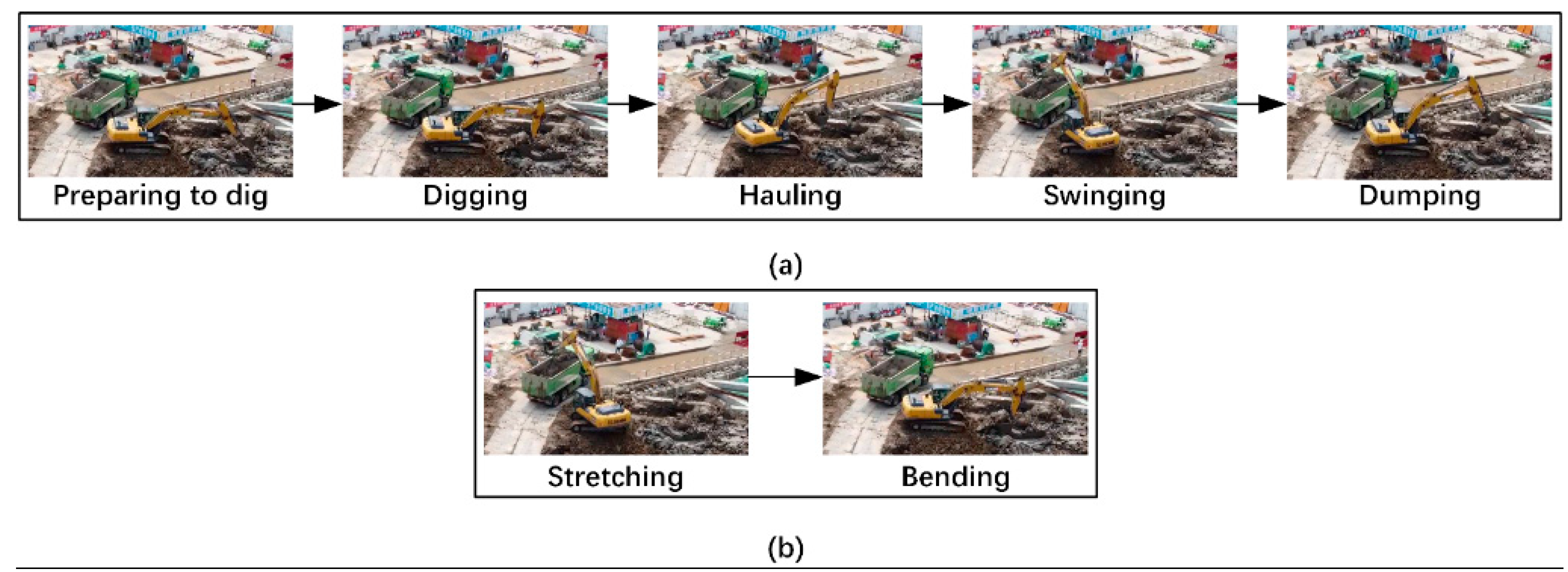
3] improved the sequential pattern with four atomic actions by adding the newly discovered atomic action “Preparing to dig”. This was used for observations at construction sites, and a sequential pattern with five atomic actions, “Preparing to dig → Digging → Hauling → Dumping → Swinging”, was constructed (see Figure 1a). However, the actions “Preparing to dig”, “Dumping”, and “Swinging” are similar in visual appearance, as all three atomic actions involve a stretched arm. The “Digging” and “Hauling” postures both involve bending arms, so they also have similar visual appearances. Thus, it is easy to misrecognize atomic actions using this method. To solve this problem, Wu et al. [3] combined “Preparing to dig”, “Dumping”, and “Swinging”, which have similar visual appearances, to form the category “Stretching”, while “Digging” and “Hauling” formed the category “Bending”. Thus, a sequential pattern (see Figure 1b) consisting of “Stretching” and “Bending” actions with different visual appearances was constructed, i.e., the “Stretching-Bending” sequential pattern (SBSP). Then, atomic actions were associated to recognize work cycles. Combining atomic actions with similar visual appearances reduced the difficulty associated with the recognition of atomic actions and work cycles [3,22]. In general, the third method can automate the recognition of work cycles for earthmoving excavators, but its application requires the use of preconstructed installation carriers as monitoring cameras at the construction site as well as installed and commissioned monitoring systems that work in tandem with them. When the installation conditions are not available at construction sites or when the construction time is short, it may be difficult to monitor the work cycles of earthmoving excavators and carry out tasks related to other earthmoving project aspects.
The recognition based on the UAV remote sensing monitoring method is flexible and mobile [24,25]. It is possible to monitor construction sites and obtain visual data in areas where surveillance cameras are difficult to install [24,26]. In recent years, this method has been widely used in the fields of engineering surveying and mapping [24], construction safety management [25,26,27,28,29,30], and construction process visualization [31]. However, few studies have been done on the application of UAV remote sensing for monitoring the working status of earthmoving excavators. Research in this area is necessary. On the one hand, the application of UAV remote sensing can reduce the impact of occlusion on the recognition of atomic actions and work cycles [32]. On the other hand, earthmoving projects are an important aspect of construction projects, and their expenditure cost is about 20% of the total cost [33]. The use of UAV remote sensing to monitor work cycles of earthmoving excavators is beneficial, as it can reduce construction costs, especially in projects with no monitoring cameras installed or projects with short construction periods, such as post-disaster reconstruction projects with harsh construction environments [34] and emergency projects with short construction periods [35,36]. UAV remote monitoring, as an alternative technology to fixed-carrier video monitoring for onsite proximity monitoring [25], can provide construction managers with a clear understanding of construction site conditions and progress [36]. This method also improves construction productivity by properly planning and deploying construction equipment based on monitoring and recording at the operational level [37]. This saves a significant amount of time and reduces costs [2,4,6,38].
The purpose of this study was to investigate the applicability of the SBSP-based recognition of work cycles for earthmoving excavators oriented toward UAV remote sensing. Unlike in projects using video data from surveillance cameras (referred to as surveillance video), a possible challenge for this study was that the stability of video data acquired by UAV remote sensing (referred to as UAV video) is easily impacted by UAV shaking [24]. At this time, undesired motion [39] in videos causes interframe instability in the video images [40]. Thus, higher-level vision tasks [41], such as the recognition of earthmoving excavators’ work cycles, are inhibited.
The details of the method used are presented in Section 2. In order to investigate the applicability of the SBSP method oriented toward UAV remote sensing, we used UAV and surveillance cameras to capture video data from earthmoving construction sites at the same location and within the same time interval. These data were then used to conduct applied and comparative experiments, as detailed in Section 3. Section 4 presents the discussion. In the last section, we conclude the study and describe future work.

2. Materials and Methods

2.1. Experimental Design

The purpose of our study was to investigate the applicability of the SBSP method oriented toward UAV remote sensing. For this, we conducted two experiments: an application and a comparison. The application experiment involved the use of the SBSP to recognize the work cycles of an earthmoving excavator in a UAV video. UAV shaking, a characteristic of UAV remote sensing data, was taken into account. The impact of UAV shaking was evaluated by comparing the recognition performance of the SBSP in the UAV video with and without stabilization processing.
The comparison experiment aimed to test whether the SBSP based on UAV remote sensing monitoring (referred to as UAV-SBSP) can be used as an alternative to the SBSP based on fixed-carrier video monitoring (referred to as FC-SBSP). An important prerequisite to ensure the effectiveness of the comparison experiment was to use a UAV video and surveillance video captured at the same construction site, and in the same time interval as the training and validation data used for the experiment. When capturing video data, UAV and surveillance cameras were located at the same height and horizontal distance from the earthmoving excavator. In addition, in order to balance the effectiveness and safety of the experiment, the horizontal distance between the UAV and tower crane where the monitoring camera was installed was as small as possible. Based on the above data, the applicability of the SBSP method oriented toward UAV remote sensing was investigated by comparing the UAV-SBSP and FC-SBSP recognition work cycles.

2.2. Experimental Data and Environment

2.2.1. Video Image Dataset

We used a DJI Mini type UAV to capture video data at an earthmoving site. The wind scale for the day was level three. When capturing video data, the UAV hovering height was 22 m, and the horizontal distance to the earthmoving excavator was 60 m. The video resolution was set to 1920 × 1080, and the frame rate was set to 25 frames per s. In total, we collected 53,125 frames representing 35 min and 25 s of earthwork time.
To ensure the effectiveness of the comparison experiment, the same number of images were captured by the surveillance camera installed on the tower crane. The height of the monitoring camera was 22 m from the ground, and the horizontal distance from the earthmoving excavator was 60 m. To prevent the UAV from colliding with the tower crane, a safety distance of 10 m was set. The video resolution was set to 1920 × 1080, and the frame rate was set to 25 frames per s. Figure 2a,b show sample images taken from the UAV video and surveillance video, respectively.
We manually selected images in the UAV video containing “Stretching” and “Bending” atomic motions of an earthmoving excavator. There were 5929 images of “Stretching” atomic actions and 5909 images of “Bending” atomic actions. Then, the atomic actions in each image were manually labeled using labelImg software (categories and bounding boxes of atomic actions in the image). From these images, 656 and 654 images and annotation files corresponding to each image were randomly selected as the test image set for the atomic action recognition model used in the UAV-SBSP. The remaining images and annotation files corresponding to each image were used as the training image set for the atomic action recognition model in the UAV-SBSP. The test image set and training image set of the atomic action recognition model used in the FC-SBSP constructed by the surveillance video were processed as described above. The validation samples were videos that were 24 min and 3 s in length. These were captured by the UAV and the surveillance camera in the same time interval and called the UAV validation video and surveillance validation video, respectively. Both the UAV validation video and surveillance validation video consisted of three videos with an average duration of 8 min and 1 s due to the short hovering time of the UAV used. Manual determination of the number of earthmoving excavator work cycles showed that there were 56 work cycles in both videos. There were 46 normal working cycles and 10 abnormal working cycles.

2.2.2. Computing Environment

Our method was developed in the Python 3.6 development environment with a 64-bit Windows 10 system. For the deep learning framework, we used Tensorflow 1.14, and for video processing, we used the open-source algorithm library OpenCV 4.4. In terms of hardware configuration, an NVIDA GeForce GTX1080Ti type GPU was used to train the atomic action recognition model. An Intel i5-10600KF type CPU was used for video stabilization, atomic action recognition, and work cycle recognition.

2.3. Methods

2.3.1. Video Stabilization

The purpose of video stabilization is to eliminate undesired motion (jitter and instability) in video data caused by UAV shaking, thereby creating a new video sequence with no undesired motion between frames [39]. Generally, this is implemented with three steps [42,43], namely, motion estimation, motion compensation, and image synthesis. We developed the video stabilization method as follows:
(1)
Motion estimation. The goal of this step was to exclude interference from local motion, such as the motion of earthmoving excavators, and to obtain accurate information about background motion in the video. We first extracted the first image and the last image from the UAV validation video. The Speeded Up Robust Features (SURF) detector [44] was then used to extract the feature points from both images. Since some of the extracted feature points were taken from the dynamic earthmoving excavator, they needed to be removed. We used the fast library for the approximate nearest neighbors algorithm (Flann) [45] to match static feature points originating from the background in two images. After this process, the static feature points of the intersection part from two images, i.e., feature templates, were retained.
(2)
Motion compensation. This step was done to correct for background motion and remove undesired motion. We first used two sets of static feature points that were successfully matched in the first and last images to calculate a homography matrix of both images:
[ x i y i 1 ] = H [ x i y i 1 ]
where ( x i , y i ) and ( x i , y i ) in Equation (1) are the static feature points in the first and last images of the video, respectively, and:
H = [ k 1 k 2 t x k 3 k 4 t y 0 0 1 ]
where t x and t y in Equation (2) are the translation vector parameters. k1, k2, k3, and k4 are the affine transformation parameters [46]. Four or more pairs of feature points must be known to solve for H .
(3)
Image synthesis. In this step, a new video image is generated based on the motion compensation result. The new image that results from the alignment of the last image with the first image is the one with the undesired motion removed. However, the border area outside the intersection of the two images will have a black edge. We used edge point pixels to complement the black edge, thus forming the first image of the new video.
(4)
Generate a new video. In this step, a new video was made using the video image with the undesired motion removed. We took the other sequential images in the original video and matched them with the first image of the new video using static feature points. Then, a homography matrix was calculated and aligned to the new first image. Newly generated sequence images were written to the new video sequentially after filling the black edge. Thus, a new video was created to remove the undesired motion.
The above video stabilization method is suitable for video scenes with few dynamic elements [41]. As feature matching takes a long time, it is suitable for the processing of historical video data. Since there were few dynamic elements in the construction site studied in this paper, and because the video data used were historical video data, this method was used to perform video stabilization on the video data acquired by UAV remote sensing.

2.3.2. Recognition of Work Cycles Using the “Stretching-Bending” Sequential Pattern (SBSP)

The SBSP

The SBSP is a new, simplified sequential pattern formed from the five atomic actions sequential pattern (Figure 1a). The SBSP consists of only two atomic actions: “Stretching” and “Bending” (Figure 1b). In the five atomic actions sequential pattern, some atomic actions have similar visual appearances, for example, “Preparing to dig”, “Dumping”, and “Swinging” are similar, and “Digging” and “Hauling” are also similar. Thus, it is difficult to accurately distinguish these atomic actions using atomic action recognition models. The visual appearances of the two atomic actions included in the SBSP, “Stretching” and “Bending”, are very different, so the atomic action recognition model can easily distinguish them. This solves the problem of misrecognition of atomic actions due to similar visual appearances [3]. Furthermore, difficulty in recognizing work cycles is reduced due to the simplification of the sequential patterns. As shown in Figure 3a, five atomic actions must be associated when recognizing work cycles using the five atomic actions sequential pattern. In contrast, as shown in Figure 3b, only two atomic actions need to be associated to recognize work cycles using the SBSP.

Atomic Action Recognition for the SBSP Using the Single-Shot Detector (SSD)

The Single-Shot Detector (SSD) [47] is one of the most popular deep learning-based object detection methods. In a previous study [3], an acceptable level of atomic action recognition performance was achieved using a specific SSD model (SSD using MobileNet-V2 [48]). Therefore, this paper utilized this SSD model to recognize atomic actions. The training parameters of the SSD model were in accordance with those used in the previous study [3]. Three main training parameters were involved: the learning rate, set to 0.04; the batch size, set to 10; and the training steps, set to 2 × 10 5 . The reason for setting the same parameters as in the literature [3] is that the literature [3] and this paper used exactly the same training and validation data, both in terms of the time and location of data collection and the environment in which the model was constructed and computed. The optimal selection of parameters is described in detail in the literature [3]. These parameters are optimal for this construction scenario.

Recognition of Work Cycles

The basic idea of work cycle recognition involves using the Intersection Over Union (IOU) method [49] to associate the first “Stretching” atomic action with the detection box of the first “Bending” atomic action in a work cycle recognized by the SSD model. The specific steps used in this study were as follows:
(a)
Information about the n ( n N + ) “Stretching” boxes were recognized in a work cycle and the time that they were recognized was stored in set D s . Then, information about the first recognized “Bending” atomic action and the time when it was recognized was stored in set D b . The equations for D s and D b are given as Equations (3) and (4), respectively:
D s = { ( d s 1 , t s 1 ) , ( d s 2 , t s 2 ) , , ( d s n , t s n ) }
D b = { ( d b 1 , t b 1 ) }
where d s 1 is the information about the first recognized “Stretching” atomic action in a work cycle. This includes the top-left pixel coordinates and the bottom-right pixel coordinates of the box. t s 1 is information about the time at which the atomic action “Stretching” is recognized.
(b)
The overlap value σ i o u of d s 1 and d b 1 was calculated using the IOU method. The calculation method used is shown as Equation (5):
σ i o u ( d s 1 , d b 1 ) = A r e a ( d s 1 )   A r e a ( d b 1 ) A r e a ( d s 1 )   A r e a ( d b 1 )
where the recognition of the work cycle is completed when the value of σ i o u is greater than zero and noted as C a 1 . t b 1 minus t b 2 yields the time required to change from “Stretching” to “Bending” in the work cycle, and this is noted as t s b . According to observations made by Wu et al. [3] at a construction site, the amount of time required to change from “Stretching” to “Bending” in a normal work cycle of an earthmoving excavator is usually greater than 6 s. The amount of time required to change from “Stretching” to “Bending” in an abnormal work cycle of an earthmoving excavator is usually between 2 and 6 s. Therefore, t s b > 6 was empirically set as the discriminating condition for normal working cycles. t s b [ 2 , 6 ] was set as the discriminating condition for abnormal work cycles.
(c)
Steps (a) and (b) were repeated. Recognition of all work cycles of the earthmoving excavator in the video sequences was completed. Each recognized work cycle was stored in set C a . Equation (6) represents the equation of C a .
C a = { C a 1 , C a 2 , , C a n }
(d)
To count the number of work cycles, the number of work cycles was set to N a . Equation (7) was used to calculate N a .
N a = C a r d ( C a )

2.3.3. Evaluation

Four metrics were used to evaluate the atomic action and work cycle recognition results: namely, precision [3,4], recall [3,4], the atomic action average recognition time [3], and the single work cycle average recognition time [3]. The calculation formulas used for precision and recall are shown in Equations (8) and (9):
P r e c i s i o n = T P T P + F P
R e c a l l = T P T P + F N
where T P is the number of true positives, which means the number of atomic actions predicted to be true and which are actually true. F P is the number of false positives, which refers to the number of atomic actions that are actually false among the atomic actions predicted to be true. F N is the number of false negatives, which means the number of atomic actions where the actual is true and the prediction is false, including the number of misdetections. The atomic action average recognition time and single work cycle average recognition time were used to evaluate the ability of the method used in this paper to recognize atomic actions and work cycles of an earthmoving excavator in video data in real time. The frame rate of the verification video data used in this paper was 25 frames per second. This means that the atomic action average recognition time and single work cycle average recognition time should have been no more than 40 ms to achieve real time recognition.

3. Results

3.1. Results of the Application Experiments

3.1.1. Atomic Action Performance of the Trained SSD Model Using UAV Video

The image set made using UAV video was divided into two parts: the test image set and the training image set. The test image set contained 656 images of “Stretching” atomic actions and 654 images of “Bending” atomic actions. The performance of the SSD model trained using this training image set to recognize atomic actions on test image sets is shown in Table 1. Table 1 shows that the trained SSD model had a precision level of 99.35% and a recall rate of 93.51% for the test image set. This indicates that the performance of the trained SSD model was acceptable. This SSD model was used to recognize the atomic actions of an earthmoving excavator in the UAV validation video.

3.1.2. Recognition without Stabilization Processing

The SSD model trained with the UAV video was used to recognize atomic actions in the UAV validation video without using stabilization processing. In order to reduce the computational resource consumption, atomic actions were recognized every 2 s, and 720 times in total. The atomic action recognition results are shown in Table 2. Table 2 shows that the trained SSD model had a precision level of 97.5% and a recall rate of 86.53% when recognizing atomic actions in the UAV validation video without stabilization processing, and the atomic action average recognition time was 27.64 ms. This illustrates that the performance of the trained SSD model in terms of recognizing atomic actions in the UAV validation video without using stabilization processing was acceptable. Some of the atomic action recognition results are shown in Figure 4. Figure 4 shows that the trained SSD model was able to correctly recognize both “Stretching” and “Bending” atomic actions in the UAV validation video without stabilization.
The results obtained when the UAV-SBSP was used to recognize earthmoving excavator work cycles in the UAV validation video without stabilization processing are shown in Table 3. Table 3 shows that the precision level when recognizing earthmoving excavator work cycles using the UAV-SBSP in the UAV validation video without stabilization processing was 91.3%, the recall rate was 75%, and the single work cycle average recognition time was 0.5 ms. Thus, the performance of this recognition method was acceptable.

3.1.3. Recognition with Stabilization Processing

The UAV validation video was first processed in 2 h, 34 min and 35 s, and the processing time for a single image was 6427.58 ms. Using the SSD model trained on the UAV video to recognize an atomic action every 2 s in the UAV validation video with stabilization processing, a total of 720 actions were recognized. The atomic action recognition results are shown in Table 4. Table 4 shows that the trained SSD model had a precision level of 97.7% and a recall rate of 88.47% when recognizing atomic actions in the UAV validation video with stabilization processing, and the atomic action average recognition time was 27.17 ms. This result indicates that the performance of the trained SSD model in terms of recognizing atomic actions in the UAV validation video using stabilization processing was acceptable. Some atomic action recognition results are shown in Figure 5. Figure 5 shows that the trained SSD model correctly recognized both “Stretching” and “Bending” atomic actions in the UAV validation video using stabilization.
The results obtained for the recognition of earthmoving excavator work cycles using the UAV-SBSP in a UAV validation video using stabilization processing are shown in Table 5. Table 5 shows that the level of precision obtained for the recognition of earthmoving excavator work cycles using the UAV-SBSP in the UAV validation video with stabilization processing was 93.75%, the recall rate was 80.36%, and the single work cycle average recognition time was 0.25 ms. Thus, the performance of this recognition method was acceptable.
Table 3 and Table 5 compare the model performance in terms of recognizing work cycles using the UAV-SBSP in the UAV validation video without and with stabilization processing. The precision and recall of the former were 2.45% and 5.36% lower than those of the latter, respectively. Obviously, the UAV-SBSP showed a better ability to recognize work cycles in the UAV validation video with stabilization processing. This indicates that UAV shaking has a negative impact on the recognition performance of the UAV-SBSP.

3.2. Results of the Comparison Experiments

3.2.1. Atomic Action Recognition Performance of the Trained SSD Model Using a Surveillance Video

The image set produced using a surveillance video was divided into two parts: a test image set and a training image set. There were 656 images containing the atomic action “Stretching” and 654 images containing the atomic action “Bending” in the test image set. The recognition results of the SSD model trained using this training image set on the test image set are shown in Table 6. Table 6 shows that the trained SSD model had a precision level of 99.39% and a recall rate of 99.31% for the test image set, indicating that the performance of the trained SSD model was acceptable. This SSD model was used to recognize the atomic actions of an earthmoving excavator in a surveillance validation video.

3.2.2. Recognition in a Surveillance Validation Video

The SSD model trained on the surveillance video was used to recognize atomic actions in the surveillance validation video once every 2 s, for a total of 720×. The recognition results are shown in Table 7. Table 7 shows that the trained SSD model had a precision level of 99.14% and a recall rate of 96.39% for recognizing atomic actions in the surveillance validation video, and the atomic action average recognition time was 27.63 ms. This result indicates that the performance of the trained SSD model in terms of recognizing atomic actions in the surveillance validation video was acceptable. Some of the atomic action recognition results are shown in Figure 6. Figure 6 shows that the trained SSD model correctly recognized both the “Stretching” and “Bending” atomic actions in the surveillance validation video.
The results obtained for the recognition of earthmoving excavator work cycles in a surveillance validation video using the FC-SBSP are shown in Table 8. Table 8 shows that the precision level for the recognition earthmoving excavator work cycles in a surveillance validation video using the FC-SBSP was 90.38%, the recall rate was 83.93%, and the single work cycle average recognition time was 0.42 ms. The recognition performance was acceptable.
In Table 5 and Table 8, the performance of the UAV-SBSP in recognizing work cycles in the UAV validation video with stabilization processing is compared with the performance of the FC-SBSP in the surveillance validation video. The precision of the former was found to be 3.37% higher than that of the latter, and the recall rate of the former was found to be 3.57% lower than that of the latter. Thus, the performance of the UAV-SBSP and FC-SBSP in terms of work cycle recognition was almost identical.

4. Discussion

4.1. Applicability of an SBSP Approach Oriented toward UAV Remote Sensing

We investigated the applicability of an SBSP approach oriented toward UAV remote sensing through application and comparison experiments. The experimental results show that the UAV-SBSP obtained almost the same working cycle recognition performance as the FC-SBSP. This shows that the SBSP is well adapted for use in UAV remote sensing and that it is feasible to monitor the work cycles of earthmoving excavators using UAV remote sensing. It also verifies that UAV remote sensing can be used as an alternative technology to fixed-carrier video monitoring for effective onsite proximity monitoring of earthmoving projects. Additionally, the UAV-SBSP can effectively determine the working status data of an earthmoving excavator. In addition, the results of this study highlight the high potential of UAV remote sensing applications for use in construction engineering, especially in construction projects where fixed-carrier video monitoring is difficult to apply, such as post-disaster reconstruction projects involving harsh construction environments and emergency projects with short construction periods. Having a high level of construction efficiency is one of the basic requirements for completing these types of projects. UAV remote sensing can use its flexibility and mobility in such projects to effectively monitor earthmoving projects and other construction aspects, increasing construction productivity, saving time, and costs.

4.2. Error Analysis of Atomic Action and Work Cycle Recognition

Self-occlusion of the earthmoving excavator is the main cause of atomic action recognition errors [3,4]. There are two reasons for self-occlusion. Firstly, there is self-occlusion of the arm of the earthmoving excavator following the rotation of the body to a certain angle. In other words, it occurs when the arm rotates to a certain angle with the body, at which time the arm points roughly in the direction of the principal point. Another reason is UAV shaking. For example, when the UAV swings to a certain position when the arm of the earthmoving excavator happens to point in the direction of the principal point, self-occlusion will occur. It is difficult to distinguish the atomic actions of earthmoving excavators using visual appearance alone when there is self-occlusion. Examples of partial self-occlusion and recognition errors that appear in the validation video used in this study are shown in Figure 7. The atomic action shown in Figure 7a is actually “Stretching”, but the SSD model incorrectly recognized it as “Bending”. The atomic action shown in Figure 7b is actually “Bending”, but the SSD model incorrectly recognized it as “Stretching”.
Self-occlusion is not only the main cause of atomic action recognition errors but also one of the causes of work cycle recognition errors. For example, when an earthmoving excavator experiences self-occlusion during a work cycle, if the atomic action is actually “Stretching” but it is incorrectly recognized as “Bending” and the sequence of atomic actions before this atomic action involves “Stretching”, the transition time between “Stretching” and “Bending” will be shortened. If the transition time is less than 6 s at this point, the work cycle is misrecognized as an abnormal work cycle. Another reason for erroneous work cycle recognition is a long transition from “Stretching” to “Bending” in some abnormal work cycles that exceed 6 s. When there is false recognition due to such reasons, we have to adjust the σ i o u parameter appropriately to obtain a better recognition performance.

4.3. Impact of UAV Shaking on the Recognition Results

The σ i o u value reflects the association between the “Stretching” and “Bending” atomic actions when recognizing a work cycle. If there is undesired motion in the video data acquired by UAV remote sensing due to UAV shaking, this leads to changes in σ i o u values. Therefore, the impact of UAV shaking on the recognition performance of the UAV-SBSP can also be reflected by the variation in σ i o u values. The blue curve in Figure 8 shows the distribution of σ i o u values for all recognized work cycles in the UAV validation video when stabilization processing was used. The tan curve shows the distribution of σ i o u values for all recognized work cycles in the UAV validation video when stabilization processing was not used. We used the blue curve as a baseline and compared the tan curve to it to evaluate the impact of UAV shaking on the variation of the σ i o u values. Most σ i o u values on the tan curve in the figure have a large variation and deviate from the baseline curve. This deviation reflects the magnitude of the UAV shaking. For example, there are some points on the tan curve that deviate from the blue curve, and it can be presumed that the magnitude of UAV shaking was larger at this time. When the magnitude of UAV shaking increases further, there will also be σ i o u values of less than zero, which can lead to work cycle misdetection. This is one of the reasons why the UAV-SBSP misses more work cycles in the UAV validation video without stabilization than in the UAV validation video with stabilization.
In addition, we compared the recognition performance of the UAV-SBSP in the UAV validation video with and without stabilization processing and found a difference in recognition accuracy between the two. Although the recognition performance of the UAV-SBSP was found to be acceptable for the UAV validation video without stabilization processing, it was better for the UAV validation video with stabilization processing. This indicates that, on the one hand, UAV shaking is indeed a challenge in the migration of SBSP to UAV remote sensing. This shaking has a negative impact on the recognition of earthmoving excavators’ work cycles, and it is necessary to perform stabilization of the video data acquired by UAV remote sensing to improve the recognition performance. On the other hand, it shows that because the recognition performance of the UAV-SBSP in the UAV validation video without stabilization processing was acceptable, it is also possible to not perform stabilization processing on the video data acquired by UAV remote sensing. Therefore, whether stabilization of video data acquired by UAV remote sensing is performed depends on the actual needs of the user and the degree of impact of UAV shaking on the recognition performance of the UAV-SBSP.

5. Conclusions

The main purpose of this study was to investigate the applicability of the SBSP approach oriented toward UAV remote sensing. To achieve this purpose, two experiments were conducted: an application experiment and a comparison experiment. In the application experiment, to reduce the impact of UAV shaking on the stability of video data acquisition, we used stabilization technology. The application experimental results show that the recognition performance using the UAV-SBSP in the UAV validation video with stabilization processing was better than in the UAV validation video without stabilization processing. This shows that the use of stabilization techniques is necessary. The results for the comparison experiment show that the recognition performance achieved when the UAV-SBSP was used for the UAV validation video with stabilization processing was almost the same as that achieved with the FC-SBSP for the surveillance validation video. This shows that the SBSP oriented toward UAV remote sensing has good applicability.
However, since the stabilization method used in this study processes video data over a long period of time, it is only applicable for the processing of historical video data. This also indicates that the methodological framework used in this study can be used as a benchmark method, and real time stabilization techniques can be incorporated into our methodological framework in the future. This is an important subject for future research. In addition, accurate recognition of earthmoving excavator atomic actions must take self-occlusion into account. Determining how to accurately recognize the atomic actions of an earthmoving excavator when self-occlusion occurs is another important subject for future research.

Author Contributions

Conceptualization, Y.W., T.M. and X.L. (Xuejun Liu); methodology, Y.W. and Z.L.; validation, Z.W.; formal analysis, X.L. (Xiuquan Li); investigation, X.W.; resources, Y.X.; data curation, D.L.; writing—original draft preparation, Y.W.; writing—review and editing, M.W.; funding acquisition, X.L. (Xuejun Liu). All authors have read and agreed to the published version of the manuscript.

Funding

This research was funded by the National Natural Science Foundation of China (41771420; 41801305), the Priority Academic Program Development of Jiangsu Higher Education Institutions (164320H116), the Postgraduate Research and Practice Innovation Program of Jiangsu Province (KYCX20_1180), and the State Scholarship Fund from the China Scholarship Council (202006860047).

Data Availability Statement

The data presented in this study are available on request from the corresponding author. The data are not publicly available due to the privacy of construction companies.

Conflicts of Interest

The authors declare no conflict of interest.

References

  1. Kim, J.; Chi, S. Multi-camera vision-based productivity monitoring of earthmoving operations. Autom. Constr. 2020, 112, 103121. [Google Scholar] [CrossRef]
  2. Chen, C.; Zhu, Z.H.; Hammad, A. Automated excavators activity recognition and productivity analysis from construction site surveillance videos. Autom. Constr. 2020, 110, 103045. [Google Scholar] [CrossRef]
  3. Wu, Y.; Wang, M.; Liu, X.; Wang, Z.; Ma, T.; Xie, Y.; Li, X.; Wang, X. Construction of Stretching-Bending Sequential Pattern to Recognize Work Cycles for Earthmoving Excavator from Long Video Sequences. Sensors 2021, 21, 3427. [Google Scholar] [CrossRef]
  4. Kim, J.; Chi, S. Action recognition of earthmoving excavators based on sequential pattern analysis of visual features and operation cycles. Autom. Constr. 2019, 104, 255–264. [Google Scholar] [CrossRef]
  5. Kim, H.; Ahn, C.R.; Engelhaupt, D.; Lee, S. Application of dynamic time warping to the recognition of mixed equipment activities in cycle time measurement. Autom. Constr. 2018, 87, 225–234. [Google Scholar] [CrossRef]
  6. Golparvar-Fard, M.; Heydarian, A.; Niebles, J.C. Vision-based action recognition of earthmoving equipment using spatio-temporal features and support vector machine classifiers. Adv. Eng. Inform. 2013, 27, 652–663. [Google Scholar] [CrossRef]
  7. Pradhananga, N.; Teizer, J. Automatic spatio-temporal analysis of construction site equipment operations using GPS data. Autom. Constr. 2013, 29, 107–122. [Google Scholar] [CrossRef]
  8. Montaser, A.; Moselhi, O. RFID+ for Tracking Earthmoving Operations; Construction Research Congress: West Lafayette, IN, USA, 2012; pp. 1011–1020. [Google Scholar]
  9. Liang, C.J.; Lundeen, K.M.; McGee, W.; Menassa, C.C.; Lee, S.; Kamat, V.R. Stacked Hourglass Networks for Markerless Pose Estimation of Articulated Construction Robots; International Symposium on Automation and Robotics in Construction: Berlin, Germany, 2018; pp. 869–875. [Google Scholar]
  10. Kim, J.; Chi, S.; Seo, J. Interaction analysis for vision-based activity identification of earthmoving excavators and dump trucks. Autom. Constr. 2018, 87, 297–308. [Google Scholar] [CrossRef]
  11. Azar, E.R.; Dickinson, S.; McCabe, B. Server-customer interaction tracker: Computer vision-based system to estimate dirt-loading cycles. J. Constr. Eng. Manag. 2013, 139, 785–794. [Google Scholar] [CrossRef]
  12. Azar, E.R.; McCabe, B. Part based model and spatial-temporal reasoning to recognize hydraulic excavators in construction images and videos. Autom. Constr. 2012, 24, 202–294. [Google Scholar]
  13. Richardson, A.D.; Braswell, B.H.; Hollinger, D.Y.; Jenkins, J.P.; Ollinger, S.V. Near-surface remote sensing of spatial and temporal variation in canopy phenology. Ecol. Appl. 2009, 19, 1417–1428. [Google Scholar] [CrossRef]
  14. Nagai, S.; Maeda, T.; Gamo, M.; Muraoka, H.; Suzuki, R.; Nasahara, K.N. Using digital camera images to detect canopy condition of deciduous broad-leaved trees. Plant Ecol. Divers. 2011, 4, 79–89. [Google Scholar] [CrossRef]
  15. Sonnentag, O.; Hufkens, K.; Teshera-Sterne, C.; Young, A.M.; Friedl, M.; Braswell, B.H.; Milliman, T.; O’Keefe, J.; Richardson, A.D. Digital repeat photography for phenological research in forest ecosystems. Agric. For. Meteorol. 2012, 152, 159–177. [Google Scholar] [CrossRef]
  16. Galvagno, M.; Siniscalco, C.; Rossini, M.; Fava, F.; Cogliati, S.; Cella, U.M.D.; Menzel, A. Using digital camera images to analyse snowmelt and phenology of a subalpine grassland. Agric. For. Meteorol. 2014, 198–199, 116–125. [Google Scholar]
  17. Jia, B. Establishment of System for Monitoring Cotton Growth Based on Computer Vision Technology. Ph.D. Dissertation, Shihezi University, Shihezi, China, 2014. [Google Scholar]
  18. Deng, L. Response of Plant Phenology to Climate Change in North China and Surveillance Camera-Based Monitoring of Plant Flowering Phenology. M.D. Dissertation, China University of Geosciences, Beijing, China, 2017. [Google Scholar]
  19. Zhan, Y.; Aarninkhof, S.G.J.; Wang, Z.; Qian, W.; Zhou, Y. Daily topographic change patterns of tidal flats in response to anthropogenic activities: Analysis through coastal video imagery. J. Coast. Res. 2019, 36, 103–115. [Google Scholar] [CrossRef]
  20. Hu, X.S.; Wang, N.Y. Research on new method of getting real-time video surveillance area based on OpenCV. Mod. Surv. Mapp. 2019, 42, 24–26. [Google Scholar]
  21. Feng, X.Y. Research on Recognition and Spatial Location Method of Construction Land Based on Tower-Based Monitoring Image. M.D. Dissertation, Nanjing Normal University, Nanjing, China, 2019. [Google Scholar]
  22. Roberts, D.; Golparvar-Fard, M. End-to-end vision-based detection, tracking and activity analysis of earthmoving equipment filmed at ground level. Autom. Constr. 2019, 105, 102811. [Google Scholar] [CrossRef]
  23. Kim, J.; Ham, Y.; Chung, Y.; Chi, S. Systematic camera placement framework for operation-level visual monitoring on construction jobsites. J. Constr. Eng. Manag. 2019, 145, 04019019. [Google Scholar] [CrossRef] [Green Version]
  24. Liu, P.; Chen, A.Y.; Huang, Y.N.; Han, J.Y. A review of rotorcraft unmanned aerial vehicle (UAV) developments and applications in civil engineering. Smart Struct. Syst. 2014, 13, 1065–1094. [Google Scholar] [CrossRef]
  25. Kim, D.; Liu, M.; Lee, S.; Kamat, V.R. Remote proximity monitoring between mobile construction resources using camera-mounted UAVs. Autom. Constr. 2019, 99, 168–182. [Google Scholar] [CrossRef]
  26. Bang, S.; Hong, Y.; Kim, H. Proactive proximity monitoring with instance segmentation and unmanned aerial vehicle-acquired video-frame predication. Comput.-Aided Civ. Infrastruct. Eng. 2021, 36, 800–816. [Google Scholar] [CrossRef]
  27. Guo, Y.; Xu, Y.; Li, S. Dense construction vehicle detection based on orientation-aware feature fusion convolutional neural network. Autom. Constr. 2020, 112, 103124. [Google Scholar] [CrossRef]
  28. Kim, K.; Kim, H.; Kim, H. Image-based construction hazard avoidance system using augmented reality in wearable device. Autom. Constr. 2017, 83, 390–403. [Google Scholar] [CrossRef]
  29. Kang, D.; Cha, Y.J. Autonomous UAVs for structural health monitoring using deep learning and an ultrasonic beacon system with geo-tagging. Comput.-Aided Civ. Infrastruct. Eng. 2018, 33, 885–902. [Google Scholar] [CrossRef]
  30. Tian, Y.; Zhang, C.; Jiang, S.; Zhang, J.; Duan, W. Noncontact cable force estimation with unmanned aerial vehicle and computer vision. Comput.-Aided Civ. Infrastruct. Eng. 2021, 36, 73–88. [Google Scholar] [CrossRef]
  31. Ham, Y.; Han, K.K.; Lin, J.J.; Golparvar-Fard, M. Visual monitoring of civil infrastructure systems via camera-equipped unmanned aerial vehicles (UAVs): A review of related works. Vis. Eng. 2016, 4, 1. [Google Scholar] [CrossRef] [Green Version]
  32. Mliki, H.; Bouhlel, F.; Hammami, M. Human activity recognition from UAV-captured video sequences. Pattern Recognit. 2020, 100, 107140. [Google Scholar] [CrossRef]
  33. Kang, S.H.; Seo, W.J.; Baik, K.G. 3D-GIS Based Earthwork Planning System for Productivity Improvement; Construction Research Congress: Seattle, WA, USA, 2009; pp. 151–160. [Google Scholar]
  34. Calantropio, A. The use of UAVs for performing safety-related tasks at post-disaster and non-critical construction sites. Safety 2019, 5, 64. [Google Scholar] [CrossRef] [Green Version]
  35. Luo, H.; Liu, J.; Li, C.; Chen, K.; Zhang, M. Ultra-rapid delivery of specialty field hospitals to combat COVID-19: Lessons learned from the Leishenshan hospital project in Wuhan. Autom. Constr. 2020, 119, 103345. [Google Scholar] [CrossRef]
  36. Chen, L.K.; Yuan, R.P.; Ji, X.J.; Lu, X.Y.; Xiao, J.; Tao, J.B.; Kang, X.; Li, X.; He, Z.H.; Quan, S.; et al. Modular composite building in urgent emergency engineering projects: A case study of accelerated design and construction of Wuhan Thunder God Mountain/Leishenshan hospital to COVID-19 pandemic. Autom. Constr. 2021, 124, 103555. [Google Scholar] [CrossRef]
  37. Kim, J. Visual analytics for operation-level construction monitoring and documentation: State-of-the-art technologies, research challenges, and future directions. Front. Built Environ. 2020, 6, 575738. [Google Scholar] [CrossRef]
  38. Zou, J.; Kim, H. Using hue, saturation, and value color space for hydraulic excavator idle time analysis. J. Comput. Civ. Eng. 2007, 21, 238–246. [Google Scholar] [CrossRef]
  39. Walha, A.; Wali, A.; Alimi, A.M. Video stabilization for aerial video surveillance. Aasri Procedia 2013, 4, 72–77. [Google Scholar] [CrossRef]
  40. Yuan, W.; Gao, Y.Q.; Wu, J.J. A UAV video stabilization method based on gray projection and block matching algorithm. Radio Eng. 2016, 46, 19–22. [Google Scholar]
  41. Lim, A.; Ramesh, B.; Yang, Y.; Xiang, C.; Gao, Z.; Lin, F. Real-time optical flow-based video stabilization for unmanned aerial vehicles. J. Real-Time Image Process. 2019, 16, 1975–1985. [Google Scholar] [CrossRef] [Green Version]
  42. Vazquez, M.; Chang, C. Real-time video smoothing for small RC helicopters. In Proceedings of the IEEE International Conference on System, Man, and Cybernetics, San Antonio, TX, USA, 11 October 2009; pp. 4019–4024. [Google Scholar]
  43. Dong, J.; Xia, Y.; Yu, Q.; Su, A.; Hou, W. Instantaneous video stabilization for unmanned aerial vehicles. J. Electron. Imaging. 2014, 23, 013002. [Google Scholar] [CrossRef]
  44. Bay, H.; Tuytelaars, T.; Gool, L.V. SURF: Speeded up robust features. In Proceedings of the European Conference on Computer Vision, Graz, Austria, 7–13 May 2006; pp. 417–440. [Google Scholar]
  45. Muja, M.; Lowe, D. Fast approximate nearest neighbors with automatic algorithm configuration. In Proceedings of the International Conference on Computer Vision Theory and Applications, Lisboa, Portugal, 5–8 February 2009; pp. 331–340. [Google Scholar]
  46. Xie, Y.; Wang, M.; Liu, X.; Mao, B.; Wang, F. Integration of multi-camera video moving objects and GIS. Int. J. Geo-Inf. 2019, 8, 561. [Google Scholar] [CrossRef] [Green Version]
  47. Liu, W.; Anguelov, D.; Erhan, D.; Szegedy, C.; Reed, S.; Fu, C.Y.; Berg, A.C. SSD: Single Shot MultiBox Detector. In Proceedings of the European Conference on Computer Vision, Amsterdam, The Netherlands, 11–14 October 2016; pp. 21–37. [Google Scholar]
  48. Sandler, M.; Howard, A.; Zhu, M.; Zhmoginov, A.; Chen, L.C. MobileNetV2: Inverted Residuals and Linear Bottlenecks. In Proceedings of the Conference on Computer Vision and Pattern Recognition, Salt Lake City, UT, USA, 18–23 June 2018; pp. 4510–4520. [Google Scholar]
  49. Cai, Z.; Vasconcelos, N. Cascade R-CNN: Delving Into High Quality Object Detection. In Proceedings of the Conference on Computer Vision and Pattern Recognition, Salt Lake City, UT, USA, 18–23 June 2018; pp. 6154–6162. [Google Scholar]
Figure 1. Atomic actions of an earthmoving excavator intercepted in a video sequence: (a) five-atomic-action sequential pattern and (b) stretching-bending sequential pattern.
Remotesensing 13 03853 g001
Figure 2. Screenshots of (a) the UAV video and (b) the surveillance video collected from an actual earthwork site. The two Chinese characters in the second photo indicate the video recording time (in the upper left corner of the picture: 15 May 2020, Monday 09:21:32) and the surveillance camera ID (in the lower right corner of the picture: the tower of Phoenix International Building #1).
Remotesensing 13 03853 g002
Figure 3. (a) Five atomic actions sequential pattern and (b) stretching-bending sequential pattern (SBSP) in video sequence (3).
Remotesensing 13 03853 g003
Figure 4. Atomic actions recognition from the UAV validation video without stabilization processing: (a) stretching and (b) bending.
Remotesensing 13 03853 g004
Figure 5. Atomic action recognition in the UAV validation video with stabilization processing: (a) stretching and (b) bending.
Remotesensing 13 03853 g005
Figure 6. Atomic action recognition in a surveillance validation video with stabilization processing: (a) stretching and (b) bending. The Chinese characters in the two pictures indicate the time of video recording and the ID of the surveillance camera, respectively. The video recording time for (a) is 15 May 20, Mon, 10:07:59. The video recording time for (b) is 15 May 20, Monday, 10:08:05. The ID of the surveillance camera is ‘the tower of Phoenix International Building #1′.
Remotesensing 13 03853 g006
Figure 7. Erroneous atomic action recognition. (a) “Stretching” is recognized incorrectly as “Bending”; (b) “Bending” is recognized incorrectly as “Stretching”. The two Chinese characters in the second photo express the recording time of this video (in the upper left corner of the picture: 15 May 2020, Mon, 09:24:52) and the surveillance camera ID (in the lower right corner of the picture: the tower of Phoenix International Building #1).
Remotesensing 13 03853 g007
Figure 8. Distribution of the σ i o u values of the work cycles in the UAV video with and without stabilization processing.
Remotesensing 13 03853 g008
Table 1. Atomic action recognition performance of the SSD model for UAV video test data.
ClassRecognition NumberMisrecognition NumberMisdetection NumberPrecision (%)Recall (%)
Stretching63672899.3593.51
Bending597149
Table 2. Atomic action recognition performance of the SSD model for the UAV validation video without stabilization processing.
ClassRecognition NumberMisrecognition NumberMisdetection NumberPrecision (%)Recall (%)Atomic Action Average Recognition Time (ms)
Stretching27923097.586.5327.64
Bending3601451
Table 3. Work cycle recognition performance of the UAV-SBSP for the UAV validation video without stabilization processing.
ClassRecognition NumberMisrecognition NumberMisdetection NumberPrecision (%)Recall (%)Single Work Cycle Average Recognition Time (ms)
Normal Work Cycles422591.3750.5
Abnormal Work Cycles426
Table 4. Atomic action recognition performance of the SSD model for the UAV validation video with stabilization processing.
ClassRecognition NumberMisrecognition NumberMisdetection NumberPrecision (%)Recall (%)Atomic Action Average Recognition Time (ms)
Stretching28423297.788.4727.17 ms
Bending3681336
Table 5. Work cycle recognition performance of the UAV-SBSP for the UAV validation video with stabilization processing.
ClassRecognition NumberMisrecognition NumberMisdetection NumberPrecision (%)Recall (%)Single Work Cycle Average Recognition Time (ms)
Normal Work Cycles442393.7580.360.25
Abnormal Work Cycles415
Table 6. Atomic action recognition performance of the SSD model for surveillance video test data.
ClassRecognition NumberMisrecognition NumberMisdetection NumberPrecision (%)Recall (%)
Stretching6520099.3999.31
Bending65781
Table 7. Atomic action recognition performance of the SSD model for the surveillance validation video.
ClassRecognition NumberMisrecognition NumberMisdetection NumberPrecision (%)Recall (%)Atomic Action Average Recognition Time (ms)
Stretching3094899.1496.3927.63
Bending391212
Table 8. Work cycle recognition performance of the FC-SBSP for the surveillance validation video with stabilization processing.
ClassRecognition NumberMisrecognition NumberMisdetection NumberPrecision (%)Recall (%)Single Work Cycle Average Recognition Time (ms)
Normal Work Cycles452090.3883.930.42
Abnormal Work Cycles734
Publisher’s Note: MDPI stays neutral with regard to jurisdictional claims in published maps and institutional affiliations.

