
Parameter-Free Half-Spaces Based 3D Building Reconstruction Using Ground and Segmented Building Points from Airborne LiDAR Data with 2D Outlines


Abstract
:1. Introduction
2. Methodology
2.1. Data Preprocessing
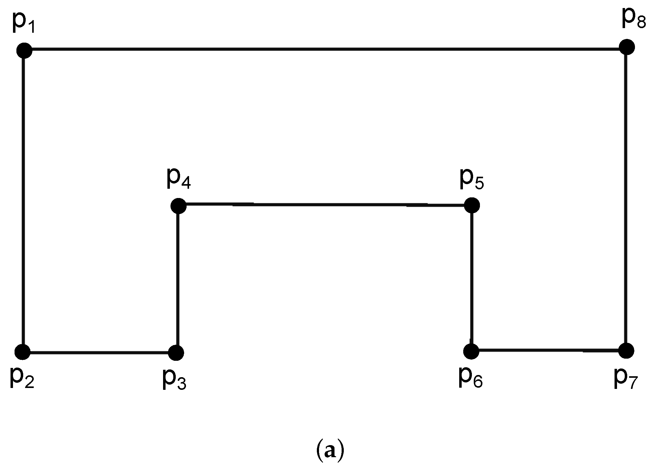
2.1.1. Generating Base Models
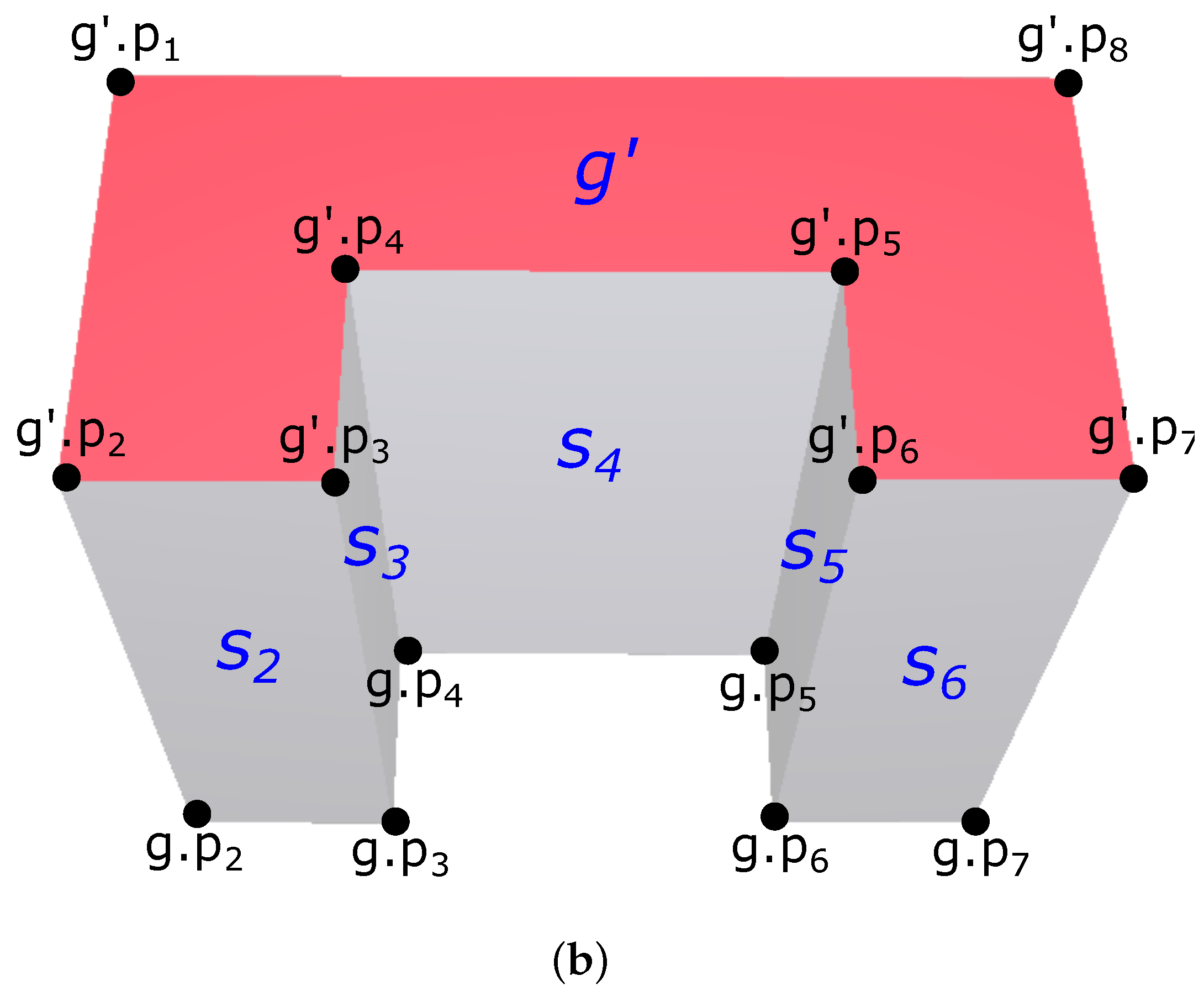
2.1.2. Half-Spaces’ Definition
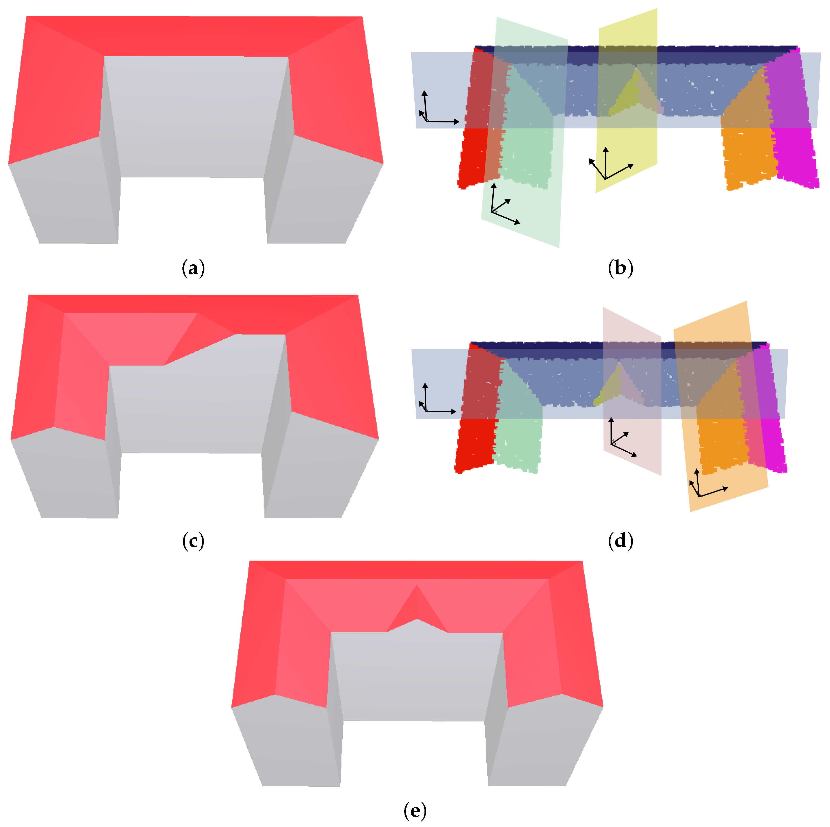
2.2. Shaping 3D Building Models by 3D Boolean Operations
Classification of Half-Spaces
2.3. Performing 3D Boolean Operations with Half-Spaces
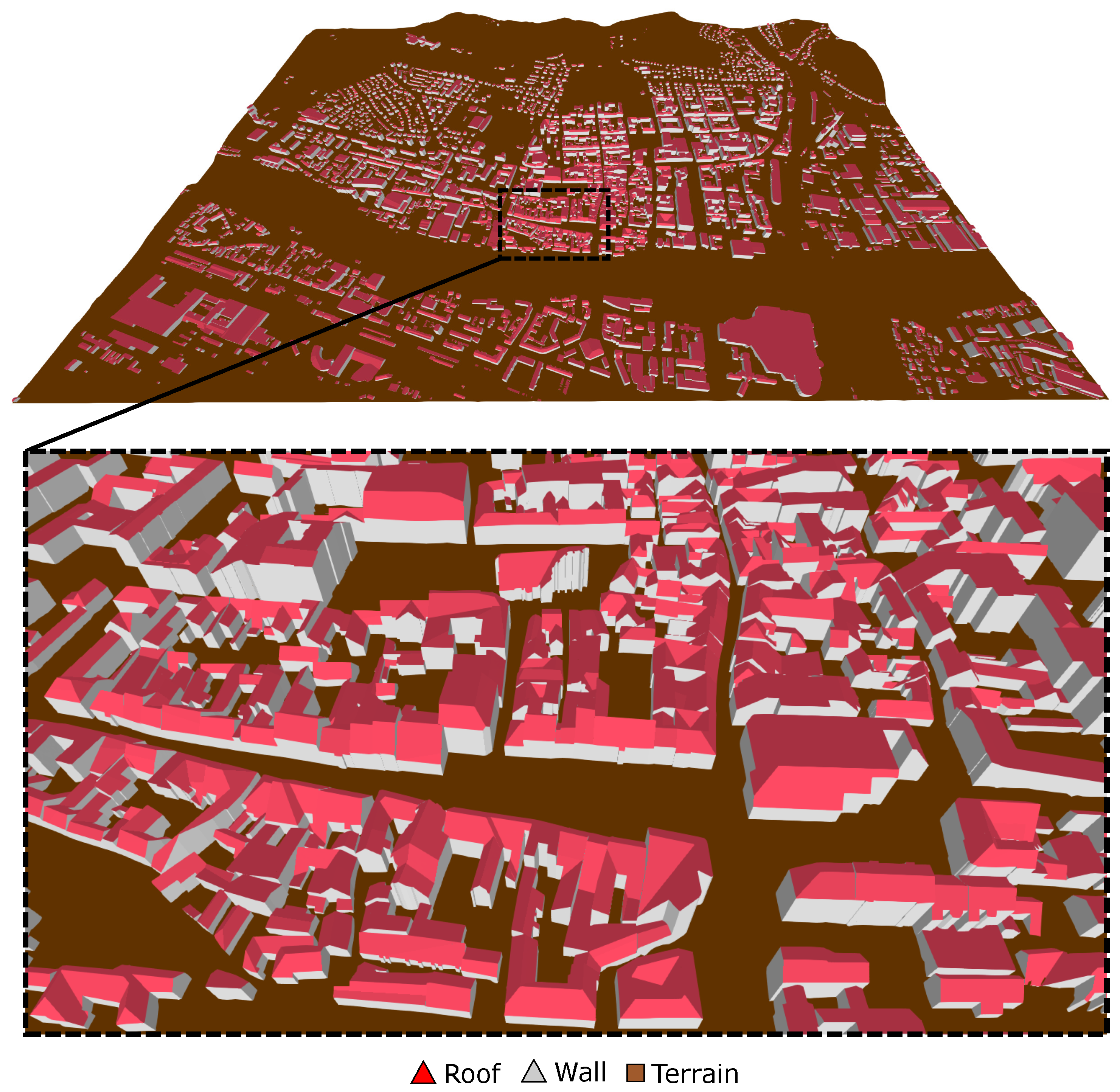
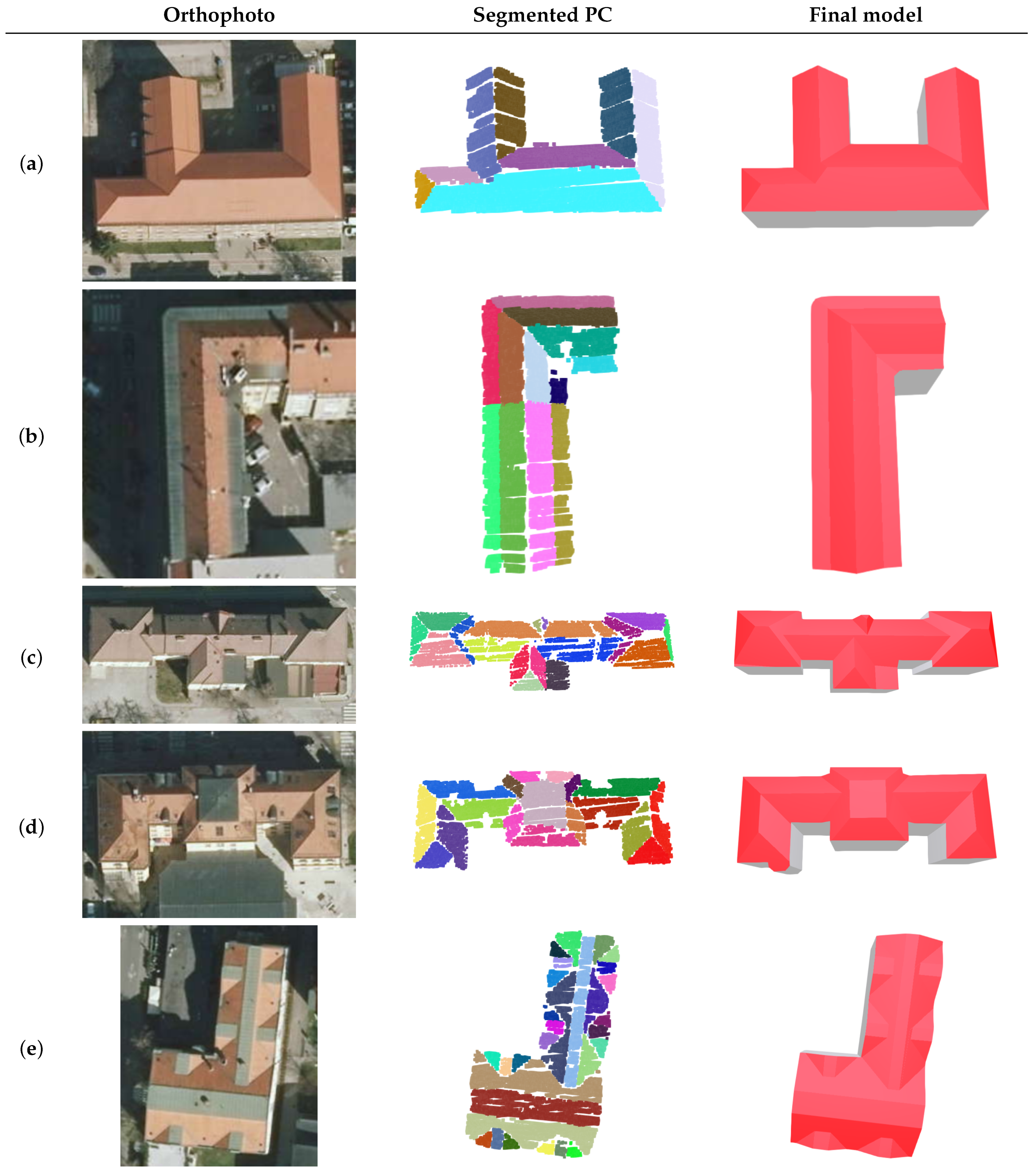
3. Results
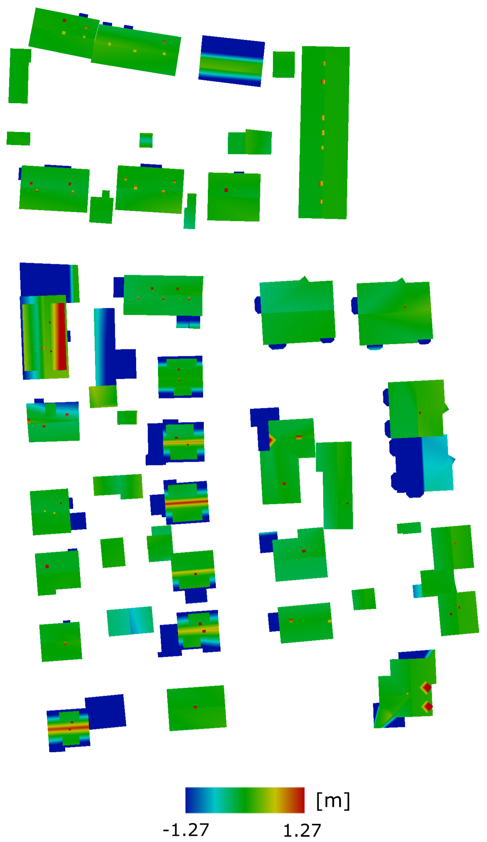
Validation
4. Discussion
5. Conclusions
Author Contributions
Funding
Acknowledgments
Conflicts of Interest
References
- Biljecki, F.; Stoter, J.; Ledoux, H.; Zlatanova, S.; Çöltekin, A. Applications of 3D City Models: State of the Art Review. ISPRS Int. J. Geo-Inf. 2015, 4, 2842–2889. [Google Scholar] [CrossRef] [Green Version]
- Bizjak, M.; Žalik, B.; Štumberger, G.; Lukač, N. Large-scale estimation of buildings’ thermal load using LiDAR data. Energy Build. 2021, 231, 110626. [Google Scholar] [CrossRef]
- Ali, U.; Shamsi, M.H.; Hoare, C.; Mangina, E.; O’Donnell, J. Review of urban building energy modeling (UBEM) approaches, methods and tools using qualitative and quantitative analysis. Energy Build. 2021, 246, 111073. [Google Scholar] [CrossRef]
- Wang, R. 3D building modeling using images and LiDAR: A review. Int. J. Image Data Fusion 2013, 4, 273–292. [Google Scholar] [CrossRef]
- Wang, R.; Peethambaran, J.; Dong, C. LiDAR Point Clouds to 3D Urban Models: A Review. IEEE J. Sel. Top. Appl. Earth Obs. Remote Sens. 2018, 11, 606–627. [Google Scholar] [CrossRef]
- Biljecki, F.; Heuvelink, G.B.; Ledoux, H.; Stoter, J. The effect of acquisition error and level of detail on the accuracy of spatial analyses. Cartogr. Geogr. Inf. Sci. 2018, 45, 156–176. [Google Scholar] [CrossRef] [Green Version]
- Rottensteiner, F.; Sohn, G.; Gerke, M.; Wegner, J.D.; Breitkopf, U.; Jung, J. Results of the ISPRS benchmark on urban object detection and 3D building reconstruction. ISPRS J. Photogramm. Remote Sens. 2014, 93, 256–271. [Google Scholar] [CrossRef]
- Tomljenovic, I.; Höfle, B.; Tiede, D.; Blaschke, T. Building extraction from Airborne Laser Scanning data: An analysis of the state of the art. Remote Sens. 2015, 7, 3826–3862. [Google Scholar] [CrossRef] [Green Version]
- Axelsson, M.; Soderman, U.; Berg, A.; Lithen, T. Roof Type Classification Using Deep Convolutional Neural Networks on Low Resolution Photogrammetric Point Clouds From Aerial Imagery. In Proceedings of the 2018 IEEE International Conference on Acoustics, Speech and Signal Processing (ICASSP), Calgary, AB, Canada, 15–20 April 2018; pp. 1293–1297. [Google Scholar]
- Zhang, L.; Zhang, L. Deep Learning-Based Classification and Reconstruction of Residential Scenes From Large-Scale Point Clouds. IEEE Trans. Geosci. Remote Sens. 2018, 56, 1887–1897. [Google Scholar] [CrossRef]
- Yu, D.; Ji, S.; Liu, J.; Wei, S. Automatic 3D building reconstruction from multi-view aerial images with deep learning. ISPRS J. Photogramm. Remote Sens. 2021, 171, 155–170. [Google Scholar] [CrossRef]
- Wichmann, A.; Agoub, A.; Schmidt, V.; Kada, M. RoofN3D: A Database for 3D Building Reconstruction with Deep Learning. Photogramm. Eng. Remote Sens. 2019, 85, 435–443. [Google Scholar] [CrossRef]
- Vosselman, G. Building Reconstruction Using Planar Faces In Very High Density Height Data. Int. Arch. Photogramm. Remote Sens. 1999, 32, 87–92. [Google Scholar]
- Dorninger, P.; Pfeifer, N. A Comprehensive Automated 3D Approach for Building Extraction, Reconstruction, and Regularization from Airborne Laser Scanning Point Clouds. Sensors 2008, 8, 7323–7343. [Google Scholar] [CrossRef] [PubMed] [Green Version]
- Elberink, S.O.; Vosselman, G. Building reconstruction by target based graph matching on incomplete laser data: Analysis and limitations. Sensors 2009, 9, 6101–6118. [Google Scholar] [CrossRef]
- Sampath, A.; Shan, J. Segmentation and reconstruction of polyhedral building roofs from aerial LiDAR point clouds. IEEE Trans. Geosci. Remote Sens. 2010, 48, 1554–1567. [Google Scholar] [CrossRef]
- Chen, Y.; Cheng, L.; Li, M.; Wang, J.; Tong, L.; Yang, K. Multiscale grid method for detection and reconstruction of building roofs from airborne LiDAR data. IEEE J. Sel. Top. Appl. Earth Obs. Remote Sens. 2014, 7, 4081–4094. [Google Scholar] [CrossRef]
- Chen, D.; Wang, R.; Peethambaran, J. Topologically Aware Building Rooftop Reconstruction From Airborne Laser Scanning Point Clouds. IEEE Trans. Geosci. Remote Sens. 2017, 55, 7032–7052. [Google Scholar] [CrossRef]
- Lafarge, F.; Mallet, C. Creating large-scale city models from 3D-point clouds: A robust approach with hybrid representation. Int. J. Comput. Vis. 2012, 99, 69–85. [Google Scholar] [CrossRef]
- Zhou, Q.Y.; Neumann, U. 2.5D building modeling by discovering global regularities. In Proceedings of the IEEE Computer Society Conference on Computer Vision and Pattern Recognition, Providence, RI, USA, 16–21 June 2012; pp. 326–333. [Google Scholar] [CrossRef]
- Chen, D.; Zhang, L.; Mathiopoulos, P.T.; Huang, X. A methodology for automated segmentation and reconstruction of urban 3-D buildings from ALS point clouds. IEEE J. Sel. Top. Appl. Earth Obs. Remote Sens. 2014, 7, 4199–4217. [Google Scholar] [CrossRef]
- Vosselman, G.; Dijkman, S. 3D building model reconstruction from point clouds and ground plans. Int. Arch. Photogramm. Remote Sens. 2001, 34, 37–44. [Google Scholar]
- Li, M.; Rottensteiner, F.; Heipke, C. Modelling of buildings from aerial LiDAR point clouds using TINs and label maps. ISPRS J. Photogramm. Remote Sens. 2019, 154, 127–138. [Google Scholar] [CrossRef]
- Wang, S.; Cai, G.; Cheng, M.; Marcato, J., Jr.; Huang, S.; Wang, Z.; Su, S.; Li, J. Robust 3D reconstruction of building surfaces from point clouds based on structural and closed constraints. ISPRS J. Photogramm. Remote Sens. 2020, 170, 29–44. [Google Scholar] [CrossRef]
- Zhang, K.; Yan, J.; Chen, S.C. A Framework for Automated Construction of Building Models from Airborne LiDAR Measurements. In Topographic Laser Ranging and Scanning: Principles and Processing, 2nd ed.; Shan, J., Toth, C., Eds.; CRC Press: Boca Raton, FL, USA, 2018; pp. 563–585. [Google Scholar]
- Shan, J.; Yan, J.; Jiang, W. Global Solutions to Building Segmentation and Reconstruction. In Topographic Laser Ranging and Scanning: Principles and Processing, 2nd ed.; Shan, J., Toth, C., Eds.; CRC Press: Boca Raton, FL, USA, 2018; pp. 459–484. [Google Scholar]
- Tarsha Kurdi, F.; Awrangjeb, M.; Liew, A.W.C. Automated Building Footprint and 3D Building Model Generation from Lidar Point Cloud Data. In Proceedings of the 2019 Digital Image Computing Techniques and Applications (DICTA), Perth, Australia, 2–4 December 2019; pp. 75–82. [Google Scholar]
- Tarsha Kurdi, F.; Awrangjeb, M.; Munir, N. Automatic filtering and 2D modeling of airborne laser scanning building point cloud. Trans. GIS 2021, 25, 164–188. [Google Scholar] [CrossRef]
- Henn, A.; Gröger, G.; Stroh, V.; Plümer, L. Model driven reconstruction of roofs from sparse LIDAR point clouds. ISPRS J. Photogramm. Remote Sens. 2013, 76, 17–29. [Google Scholar] [CrossRef]
- Poullis, C.; You, S. Photorealistic large-scale Urban city model reconstruction. IEEE Trans. Vis. Comput. Graph. 2009, 15, 654–669. [Google Scholar] [CrossRef] [PubMed]
- Huang, H.; Brenner, C.; Sester, M. A generative statistical approach to automatic 3D building roof reconstruction from laser scanning data. ISPRS J. Photogramm. Remote Sens. 2013, 79, 29–43. [Google Scholar] [CrossRef]
- Haala, N.; Brenner, C. Virtual city models from laser altimeter and 2D map data. Photogramm. Eng. Remote Sens. 1999, 65, 787–795. [Google Scholar]
- Kada, M.; McKinley, L. 3D Building Reconstruction from LIDAR based on a Cell Decomposition Approach. In Proceedings of the CMRT09: Object Extraction for 3D City Models, Road Databases and Traffic Monitoring—Concepts, Algorithms and Evaluation, Paris, France, 3–4 September 2009; Volume XXXVIII, pp. 47–52. [Google Scholar]
- Kada, M.; Wichmann, A. Feature-Driven 3d Building Modeling Using Planar Halfspaces. ISPRS Ann. Photogramm. Remote Sens. Spat. Inf. Sci. 2013, II-3/W3, 37–42. [Google Scholar] [CrossRef] [Green Version]
- Verma, V.; Kumar, R.; Hsu, S. 3D Building Detection and Modeling from Aerial LiDAR Data. In Proceedings of the 2006 IEEE Computer Society Conference on Computer Vision and Pattern Recognition, New York, NY, USA, 17–22 June 2006; Volume 2, pp. 2213–2220. [Google Scholar] [CrossRef]
- Xiong, B.; Oude Elberink, S.; Vosselman, G. A graph edit dictionary for correcting errors in roof topology graphs reconstructed from point clouds. ISPRS J. Photogramm. Remote Sens. 2014, 93, 227–242. [Google Scholar] [CrossRef]
- Xiong, B.; Jancosek, M.; Oude Elberink, S.; Vosselman, G. Flexible building primitives for 3D building modeling. ISPRS J. Photogramm. Remote Sens. 2015, 101, 275–290. [Google Scholar] [CrossRef]
- Yan, W.Y.; Shaker, A.; El-Ashmawy, N. Urban land cover classification using airborne LiDAR data: A review. Remote Sens. Environ. 2015, 158, 295–310. [Google Scholar] [CrossRef]
- Mongus, D.; Lukač, N.; Žalik, B. Ground and building extraction from LiDAR data based on differential morphological profiles and locally fitted surfaces. ISPRS J. Photogramm. Remote Sens. 2014, 93, 145–156. [Google Scholar] [CrossRef]
- Rabbani, T.; den Heuvel, F.; Vosselmann, G. Segmentation of point clouds using smoothness constraint. Int. Arch. Photogramm. Remote Sens. Spat. Inf. Sci. 2006, 36, 248–253. [Google Scholar]
- Bizjak, M. The segmentation of a point cloud using locally fitted surfaces. In Proceedings of the 18th Mediterranean Electrotechnical Conference: Intelligent and Efficient Technologis and Services for the Citizen, MELECON, Limassol, Cyprus, 18–20 April 2016; pp. 1–6. [Google Scholar] [CrossRef]
- Czerniawski, T.; Sankaran, B.; Nahangi, M.; Haas, C.; Leite, F. 6D DBSCAN-based segmentation of building point clouds for planar object classification. Autom. Constr. 2018, 88, 44–58. [Google Scholar] [CrossRef]
- Li, L.; Yao, J.; Tu, J.; Liu, X.; Li, Y.; Guo, L. Roof plane segmentation from airborne LiDAR data using hierarchical clustering and boundary relabeling. Remote Sens. 2020, 12, 1363. [Google Scholar] [CrossRef]
- Nguyen, A.; Le, B. 3D point cloud segmentation: A survey. In Proceedings of the 6th IEEE Conference on Robotics, Automation and Mechatronics (RAM), Manila, Philippines, 12–15 November 2013; pp. 225–230. [Google Scholar]
- Bevington, P.R.; Robinson, D.K. Data Reduction and Error Analysis for the Physical Sciences, 3rd ed.; McGraw–Hill: New York, NY, USA, 2002. [Google Scholar]
- Cramer, M. The DGPF-Test on Digital Airborne Camera Evaluation Overview and Test Design. Photogramm.—Fernerkund.—Geoinf. 2010, 2010, 73–82. [Google Scholar] [CrossRef]
- Rottensteiner, F.; Sohn, G.; Jung, J.; Gerke, M.; Baillard, C.; Benitez, S.; Breitkopf, U. The ISPRS benchmark on urban object classification and 3D building reconstruction. ISPRS Ann. Photogramm. Remote Sens. Spat. Inf. Sci. 2012, I-3, 293–298. [Google Scholar] [CrossRef] [Green Version]


| Parameter | Value |
|---|---|
| k | 20 |
| 2.0 | |
| 50 | |
| [m] | 2 |
| Metric | Value |
|---|---|
| RMSE [m] | 1.31 |
| Completeness [%] | 98.9 |
| e0.5 [%] | 79.4 |
Publisher’s Note: MDPI stays neutral with regard to jurisdictional claims in published maps and institutional affiliations. |
© 2021 by the authors. Licensee MDPI, Basel, Switzerland. This article is an open access article distributed under the terms and conditions of the Creative Commons Attribution (CC BY) license (https://creativecommons.org/licenses/by/4.0/).
Share and Cite
Bizjak, M.; Žalik, B.; Lukač, N. Parameter-Free Half-Spaces Based 3D Building Reconstruction Using Ground and Segmented Building Points from Airborne LiDAR Data with 2D Outlines. Remote Sens. 2021, 13, 4430. https://doi.org/10.3390/rs13214430
Bizjak M, Žalik B, Lukač N. Parameter-Free Half-Spaces Based 3D Building Reconstruction Using Ground and Segmented Building Points from Airborne LiDAR Data with 2D Outlines. Remote Sensing. 2021; 13(21):4430. https://doi.org/10.3390/rs13214430
Chicago/Turabian StyleBizjak, Marko, Borut Žalik, and Niko Lukač. 2021. "Parameter-Free Half-Spaces Based 3D Building Reconstruction Using Ground and Segmented Building Points from Airborne LiDAR Data with 2D Outlines" Remote Sensing 13, no. 21: 4430. https://doi.org/10.3390/rs13214430
APA StyleBizjak, M., Žalik, B., & Lukač, N. (2021). Parameter-Free Half-Spaces Based 3D Building Reconstruction Using Ground and Segmented Building Points from Airborne LiDAR Data with 2D Outlines. Remote Sensing, 13(21), 4430. https://doi.org/10.3390/rs13214430