1. Introduction
The global navigation satellite system (GNSS) has been widely used in positioning, navigation, and timing. The GNSS satellite orbit serves as a reference datum in connection to the International GNSS Service (IGS)-defined reference frame [
1], not only for GNSS ranging measurements but also for the so-called precise point positioning (PPP) technique. Therefore, the accuracy of the reference orbit is crucial for precise geodetic applications.
In GNSS orbit modeling, the accuracy of the reference orbits is mainly associated with the solar radiation pressure (SRP). The Empirical CODE Orbit Model (ECOM) developed by CODE (Center for Orbit Determination in Europe), herein referred to as ECOM1, is widely used to take care of the SRP effect on the GNSS satellite in the IGS community [
2,
3]. However, the GNSS orbit accuracy is mainly dominated by the ECOM1 parameterizations, which are not suitable for an elongate satellite such as GLONASS and GALILEO. The ECOM1 biases the estimations of orbits and clocks for both GLONASS and GALILEO [
4,
5]. The elongate satellite requires the even-order harmonic terms in the satellite–Sun direction to account for the bias from the ECOM1, and this model is herein referred to ECOM2 [
6]. The major difference between ECOM1 and ECOM2 is periodic parameterizations in the satellite–Sun direction. The different parameterizations may result in different accuracies of the reference orbits. Furthermore, the ECOM2 has deficiencies in determining GLONASS orbital parameters inside the eclipse, where a non-nominal attitude model was used [
7,
8]. This indicates that the difference between the nominal attitude and the non-nominal attitude may not be completely absorbed by the ECOM1 or ECOM2 parameters during the eclipse.
On the other hand, the phase angle of 1 cycle per revolution (CPR) terms changes its sign when the sign of the β angle is changed [
9]. This implies that the interaction between the SRP force and the satellite orbit motion may result in a systematic effect on the orbit determination. Furthermore, the impact of the satellite attitude control on the orbit determination also deserves attention. The GPS IIR satellite has maximum yaw rates until the nominal yaw is retrieved during midnight-turn maneuvers [
10]. According to yaw angles retrieved by the reverse kinematic PPP technique, the GPS IIF satellite may have a disagreement between the observed yaw and the nominal yaw at β ≈ 0° [
8,
11]. Such yaw or yaw-rate misalignments may degrade the GNSS measurement accuracy and hinder the orbit determination.
The objective of this study was to develop a hybrid ECOM model, termed ECOMC, which is a combination of ECOM1 and ECOM2, for the SRP effect on GNSS orbit modeling in Ginan software. Ginan was developed by Geoscience Australia and is an open-source GNSS data-processing software. Since all GPS satellite buses are not perfectly cubic, ECOM1 may not perfectly work for the GPS IIR and IIF satellites for reference orbit modeling. Furthermore, the IIR and IIF have different features in the satellite attitude control. A combination of odd- and even-order CPR terms in the satellite–Sun direction might effectively deal with the disagreement between the nominal attitude and the non-nominal attitude. As such, the ECOMC SRP model is proposed for consistently optimizing the reference orbit.
In this paper, the ECOM-based models and their parameter estimations are discussed in
Section 2 and
Section 3, respectively. In order to understand the dependence between the ECOM-based parameters, an analysis of parameter correlation is conducted and discussed in
Section 4. Additionally,
Section 5 and
Section 6 present the orbit quality assessment via the orbit difference with respect to the IGS final product and orbit overlap at day boundaries, respectively.
Section 7 assesses the impact of the reference orbit on the estimation of station coordinates using the PPP technique. Conclusions are given in
Section 8.
2. ECOM-Based Models
For the reference orbit modeling, the SRP is the largest nongravitational force acting on the satellite and is most difficult to model. Here, the ECOM-based SRP models are specifically designed for a GNSS satellite operated with the so-called yaw-steering attitude mode [
12]. The ECOM-based model is decomposed into three orthogonal axes as
where
is an unit vector associated with a geocentric satellite position vector
,
is the geocentric position vector of the Sun,
points to the Sun direction from the satellite,
is parallel to the rotation axis of the solar panel and is always perpendicular to the
vector, and the
vector is given by the righthand rule of
and
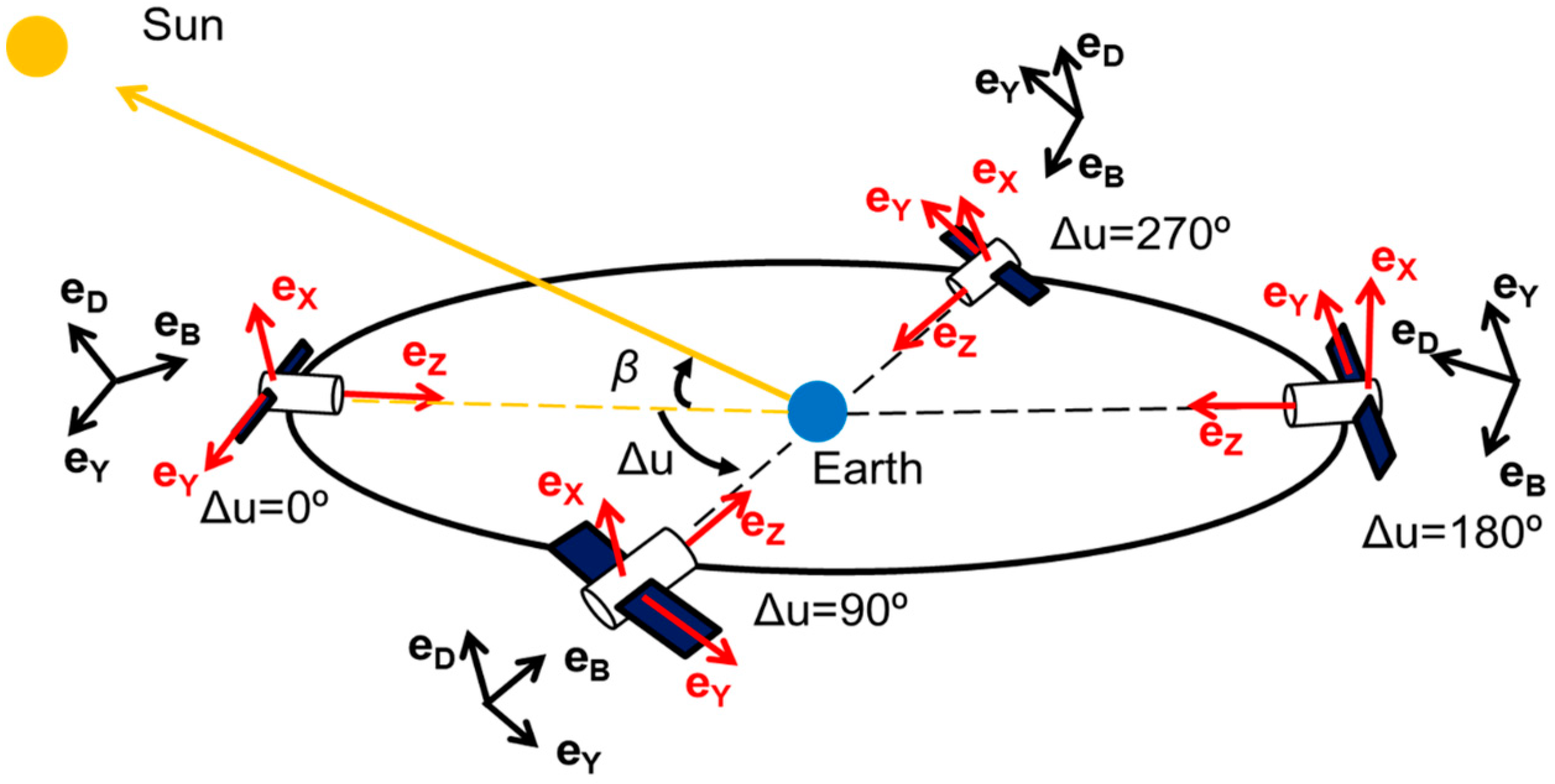
, as shown in
Figure 1. Note that the
Y-axis in the ECOM-based model (in black) is always aligned with that in the satellite attitude (in red). The so-called Sun-fixed frame is constructed by
and β, where β is the Sun elevation angle with respect to the orbit plane, and
denotes the argument of latitude of the satellite with respect to the Sun. In a case of low β, Equation (1) may suffer from a collinear problem between
and
, particularly for the orbit noon (
= 0°) and orbit midnight (
= 180°), where the orbit anomalies are frequently occurred.
In the case of |β| = 90°,
always points to the Sun from the satellite body X side. In comparison, when β = 0°,
points to the Sun direction from the satellite body −Z, Z, and X side at
= 0°, 180°, and 90°/270°, respectively. In the case of β = 0°, the frequent variations of the illuminated areas among the satellite body X, Z, and −Z sides lead to an increase in the yaw rate or a yaw variation that needs to be handled. Otherwise, an error, called phase wind-up, will be introduced into the GNSS measurement [
13]. In general, the phase wind-up error is well handled by the nominal satellite attitude. However, when the yaw rate exceeds the physical maximum threshold, the error caused by the non-nominal attitude control may degrade the GNSS ranging measurement accuracy and hinder GNSS-related solutions. The attitude misalignment often happens around orbit noon (∆u = 0°) and orbit midnight (∆u = 180°), where the yaw rate may exceed its physical limitation.
The ECOM1 is expressed using nine deterministic coefficients as follows:
where D, Y, and B are the total acceleration along the unit vectors
,
, and
, respectively. ECOM1 with five deterministic coefficients, namely, D
0, Y
0, B
0, B
C, and B
S, presents the better fitting result to the GNSS tracking measurements than that with nine coefficients. However, it is recommended to use ECOM1 with nine coefficients in generating the reference orbit from the orbit fitting, where the satellite position is regarded as a pseudo-observation, as compared to that with five coefficients [
14].
On the other hand, ECOM1 does not work well for an elongate satellite with different cross-section areas of the satellite body X and Z sides (see
Figure 1). ECOM2 was developed to overcome the deficiency of ECOM1 using the even-order periodical perturbations in the D direction [
6]. The ECOM2 model is written as
Both ECOM1 and ECOM2 may have deficiencies in modeling the reference orbit [
5,
7]. As such, a hybrid ECOMC model to compensate for the deficiencies of ECOM1 and ECOM2 is proposed. Taking into account the ECOM1 parameterizations, the ECOMC model additionally adds the 2 and 4 CPR terms in the D direction.
ECOMC has 13 parameters, and the different parameterizations may result in different estimations of the SRP-induced acceleration, particularly for the D direction. It would be interesting to analyze the common parameters from the three models, e.g., D0, Y0, and B0.
3. SRP Parameter Estimations
The so-called orbit fitting technique was used to estimate the SRP parameters of ECOM1, ECOM2, and ECOMC. The daily GPS satellite positions from the IGS orbits were used as pseudo-observations to estimate the initial state vector and the SRP parameters. Here, the so-called stochastic pulse orbit modeling technique was not used.
In general, the difference between orbit determination and orbit fitting is the type of observation. For orbit determination, the type of observation is a microwave-based ranging measurement. In comparison, the observation type for orbit fitting is the satellite position. Furthermore, the orbit determination complicatedly handles various ranging measurement errors such as satellite and station clock errors, signal delays caused by the atmosphere, ambiguous resolution, other hardware-related errors (e.g., phase center offset and phase center variation), and multipath errors. However, this is not the case for orbit fitting, which simply uses the satellite positions from orbit determination and does not deal with measurement-related errors.
Table 1 summarizes the force models used in orbit fitting. A static geopotential model, GOCO05, was used for modeling the effect caused the inhomogeneous mass distribution of the Earth. The JPL DE430 ephemeris was used for the N-body effect. The standard models for both the tidal and the relativistic effects follow the recommendations of the IERS Conventions 2010. Furthermore, both the Earth albedo and the satellite antenna thrust were modeled in line with [
15,
16]. The SRP effect was handled by the ECOM-based models. Note that no a priori SRP value was introduced in order to actually reflect the estimation of the SRP parameters.
Here, the three major parameters D0, Y0, and B0 were analyzed. D0 reflects the direct SRP acceleration acting on the satellite. Y0 accounts for the acceleration caused by the Y-bias effect, which is interpreted as a misalignment angle of the solar panel with respect to the nominal location and produces a constant acceleration along the
Y-axis [
21]. B0 accounts for a constant acceleration around the
Y-axis [
22].
Figure 2 shows the estimations of D0, Y0, and B0 as a function of β angle for GPS IIF and IIR satellites in 2018. Here, PRN 04 and 18 were excluded in the data analysis since their Y0 accelerations suddenly changed from positive to negative in 2018. Such a change might be associated with the satellite attitude maneuvers.
In both IIF and IIR cases, the Y0 estimation from ECOM2 did not show similarity to that from ECOM1 and ECOMC, and the B0 estimation from ECOM2 showed a significant difference to that from the other two models. Note that the ECOM2 B0 around β = −30° for both IIF and IIR cases showed unstable estimation, which was not found in ECOM1 and ECOMC. Furthermore, the D0 estimations were quite different among the three models. The D0 estimations in the IIF satellites depended little on the β angles, but those in the IIR satellites varied with β. The inconsistency of the D0 estimations was likely caused by the exchanges of the illuminated cross-section areas, which are differently handled in ECOM1, ECOM2, and ECOMC.
Figure 3 shows the difference in D0 when using ECOM1, ECOM2, and ECOMC. In the IIF case, no significant bias was found in the D0 differences. Only some satellites over the high β = 60–80° showed relatively large fluctuations around the zero-mean for ECOMC-ECOM1 and ECOMC-ECOM2. Note that the order of magnitude for the difference was almost 100–1000 times smaller than that for the D0 effect (10
−7 level) and only caused a few mm-cm errors in orbit. However, this was not the case for the IIR satellites. Thus, we conclude that these fluctuations are satellite-specific, rather than deficiencies of the ECOMC model. There is no significant clue that these fluctuations led to poor orbit solutions (see
Section 5 and
Section 6).
Both ECOMC-ECOM1 and ECOM2-ECOM1 differences commonly presented a bias that varied with the β angles. Such a bias was mainly caused by ECOM1. More specifically, this bias was associated with interactions between the IIR orientation changes and the D0 estimation in ECOM1. However, this bias was not discovered in the ECOMC-ECOM2 difference. This indicates that ECOM1 may bias the reference orbit solution of the IIR. Furthermore, the D0 difference showed larger fluctuations for the IIR over |β| < 4° (the gray block). These fluctuations are mainly associated with the contributions of the CPR terms to the D0 estimation (see
Section 4).
4. Parameter Correlations
The parameter correlation analysis presents the interaction among estimated parameters. Such a correlation analysis is helpful for inspecting the impact of the β angle on the ECOM parameters. Note that the parameter correlation analysis in this work was only applied to orbit fitting using the satellite positions, rather than orbit determination with real tracking data. This is because the satellite initial state vector and the SRP parameters may interact with those parameters in modeling the ranging measurement.
Figure 4 shows correlations among ECOM1 parameters as a function of β angle for both IIF and IIR satellites. We output daily matrices of the parameter correlation with the corresponding β angle for all IIF and IIR satellites. Here, the correlations between the initial state vector and SRP parameters were ignored. All parameters correlated with D0, Y0, and B0. In this correlation matrix, each SRP parameter (e.g., ECOM1) was allocated a different color, which was evenly distributed in a color map. When plotting 1 day correlation (e.g., the D0-D0 correlation is regarded as one), nine different color points (D0, Y0, B0, DC, DS, YC, YS, BC, and BS) are presented at the corresponding β angle value. As such, the β-related correlations are clearly presented when a year correlation is assessed. In order to clearly present the parameter correlation, we only selected two satellites: PRN23 as representative of the IIR group and PRN32 as representative of the IIF group.
In the ECOM1 case, the D0 significantly showed β-related correlations with YS (purple) and BC (pink). Here, the sign of the D0-YS correlation was consistent with that of β angle. Such a sign variation was mainly associated with the nominal yaw attitude control. In the case of small β angles, the
Y-axis was approximately collinear to the cross-track direction. The
Y-axis changes its sign when the sign of the β angle is changed (see Equation (1)). This was also evidenced in [
9]. Moreover, the CPR terms in the
Y-direction are mainly used to take care of the nominal yaw-rate [
9]. On the other hand, the D0-DS correlation (light blue) increased during the eclipse for the IIR satellite. However, this was not the case for the IIF satellites. This implies that the DS contribution to the D0 estimation is block type-specific. In addition, the Y0 and B0 significantly showed a β-related correlation with DS (light blue) and DC (green), respectively.
Figure 5 shows correlations among ECOM2 parameters as a function of β angle for both IIF and IIR satellites. D0 clearly showed β-related correlations with BC (green), D2C (blue), and D4C (pink). Here, the impact of D4C on the D0 estimation was relatively small compared to the other two. Note that the D0-BC correlation was not similar to that in the ECOM1 case. In general, for a yaw-steering GNSS, BC accounted for the periodic force around the
Y axis. This indicates that the BC contribution to the D0 estimation in the low β was larger than that in the high β because the satellite orientation was constantly changed over the low β (ECOM1 case in
Figure 4). However, this was not the case for ECOM2. The D0-BC correlation did not realistically reflect the yaw-steering attitude control during high β, where the BC should be little correlated with D0.
On the other hand, the D0-Y0 correlation for the IIR became noisier than that for the IIF. This implies that the IIR satellite constantly aligned the solar panel beam to the nominal location, resulting in a relatively high D0-Y0 correlation. This can also be observed in the Y0-D2 correlation. In the ECOM2 case, B0 (yellow-green) did not show any significant β-related correlation with the D harmonic terms.
Figure 6 shows correlations among ECOMC parameters as a function of β angle for both IIF and IIR satellites. The D0 estimation was sensitive to YS (light blue), BC (blue), and D2C (purple). Note that the D4C impact on D0 estimation in ECOMC was less significant than that in ECOM2. Moreover, Y0 was highly correlated with the DS (green), implying that the 1 CPR term in the D direction affects the Y0 estimation. Overall, the parameter correlations in both Y and B directions for ECOMC were similar to those for ECOM1. Note that the pattern of the D0-BC correlation in ECOM2 (
Figure 5) no longer existed in the ECOMC case. More specifically, ECOMC reflects the importance of the 1 and 2 CPR terms in estimating D0, implying that ECOMC may compensate for the deficiencies of both ECOM1 and ECOM2 in forming the reference orbit.
5. Orbit Differences with Respect to IGS Product
The reference orbits individually derived by ECOM1, ECOM2, and ECOMC were compared to the IGS final orbit. The orbit difference indicates the inconsistency between the force models used for generating the reference orbit and the IGS orbit.
Figure 7 shows the orbit difference in the radial, along-track, and cross-track directions for IIF. The orbit difference derived by ECOM1 was similar to that derived by ECOMC. However, ECOM2 showed relatively large orbit differences in the cross-track direction.
Figure 8 shows the orbit difference in the radial (R), along-track (T), and cross-track (N) directions for IIR. The orbit difference in the ECOM1 case showed periodic variations in the RTN directions. Such periodic variations were removed in the ECOM2 case, suggesting that the 2 and 4 CPR terms in the D direction absorbed these periodic variations. However, ECOM2 also produced the relatively large orbit differences in the N direction for the IIR. Both periodic variations and large orbit differences were removed in the ECOMC solution, which compensated for the deficiencies of both ECOM1 and ECOM2.
Table 2 shows the RMS of the orbit difference (in cm) between the constructed reference orbit and IGS final orbit. ECOM2 presented relatively large RMS values for IIF and IIR, as compared to ECOM1 and ECOMC. ECOM1 produced larger RMS in the radial and along-track directions for the IIR than ECOM2. This is because ECOM1 showed periodic variations of the orbit differences. Overall, the results from ECOMC overwhelmed those from ECOM1 and ECOM2. The RMS in the ECOMC case was better than that in the ECOM2 case by ~40%, ~10%, and ~55% in the R, T, and N directions, respectively. In addition, a test where the 1 CPR terms in the D direction were added to ECOM2 was set up for comparison. The result shows that the RMS improvement of ECOM2 + D1CPR over ECOM2 was approximately ~40% and ~50% in the R and N directions, respectively. However, the RMS in the along-track direction was not significantly improved. As a result, the 1 CPR terms in the D direction greatly reduced the orbit mismodeling in the radial and cross-track directions when the reference orbit was created using ECOMC.
From the above discussion, two issues were confirmed: (1) ECOM1 produces periodic orbital variations for the IIR only, and (2) ECOM2 yields a larger orbit error in the cross-track direction for both IIF and IIR satellites. For the former, the periodic variations are explained by the interactions among the satellite attitude control, the SRP force, and the orbital frame. Such an interaction cannot be well handled by ECOM1.
Figure 9 shows an illustration of the interaction between the SRP force and the orbital frame. For the radial direction, the SRP force points in the same direction as the R vector at the orbit midnight and in the opposite direction to the R vector at the orbit noon, resulting in different signs of the satellite acceleration. This interaction also happened in both the along-track and the cross-track directions. However, the cross-track had an additional effect from the β sign changes. On the other hand, larger cross-track orbit errors were only discovered in the ECOM2 case. This suggests that a systematic deficiency may exist in the ECOM2 model when the reference orbit is constructed from orbit fitting.
The unknown systematic deficiency in ECOM2 is mainly associated with the acceleration induced by the 2 and 4 CPR terms.
Figure 10 shows the recovered acceleration caused by the CPR terms in the D direction for IIF and IIR. The variation of the ECOM2-derived acceleration was similar to that of the ECOM2-derived orbit difference in the cross-track direction (
Figure 7 and
Figure 8). In general, the difference between two orbits is mainly associated with the difference between the accelerations recovered from the two orbits. Thus, the cross-track orbit differences in
Figure 7 and
Figure 8 resulted from a projection of the acceleration difference (i.e., orbit difference) in the D direction onto the invariant orbit normal vector (N direction in
Figure 9). Note that this resulting projection was still scaled by a cosine function with an angle between the D acceleration vector and the N vector. In comparison, the radial and along-track directions always changed due to the satellite motion (
Figure 9).
However, this was not the case for ECOMC, which did not show the systematic pattern of orbit difference in the cross-track direction. This is thanks to the fact that the estimation of the 1 CPR term in the satellite-Sun (D) direction absorbs the orbit mismodeling which was discovered in the ECOM2 case. Furthermore, as discussed in
Section 4, the 1 CPR terms contribute to the D0 estimation in the ECOMC case. Thus, the 1 CPR terms may effectively absorb the orbit mismodeling when the reference orbit is constructed using the pseudo-observations.
Table 3 shows the contributions of the CPR terms to SRP-induced acceleration in the D direction. The contributions of the CPR terms in ECOM2 to the acceleration estimation in the D direction was intrinsically zero at
= 90° and 270°, whereas those in ECOM1 and ECOMC were not zero (Equations (2)–(4)). This suggests that the 1 CPR terms may stabilize the estimations of the 2 and 4 CPR terms in the ECOMC case.
Figure 11 shows the estimations of 2 and 4 CPR parameters in ECOM2 and ECOMC. The 2 and 4 CPR parameters in ECOMC (green) were stably estimated for IIF and IIR, while those parameters in ECOM2 (red) were unstable. Note that the 2 and 4 CPR parameters in ECOM2 for IIF showed the large estimations at β ≈ 0°. This might be due to the fact that the IIF satellite has a disagreement between the observed yaw and the nominal yaw at β ≈ 0° [
8,
11]. However, this was not the case for ECOMC with the 1 CPR terms estimated. The periodic perturbation forces on GPS may be caused by the wobbling of the solar panel around its nominal location [
23]. In other words, such periodic perturbations may be projected to the D direction and are partially absorbed by the 1 CPR terms.
6. Orbit Accuracy Assessment
The satellite laser ranging (SLR) capability is still under development in Ginan. In general, the SLR is used to validate the reference orbit, which, for example, results from the orbit fitting in this work. In other words, this indicates that the accuracy of the reference orbit is dominated by the accuracy of the pseudo-observations in this work. The satellite position discontinuity between the end of one SP3 orbit and the beginning of the next was roughly approximate to the SLR result [
24]. Furthermore, the SLR is only capable of 1D radial orbit validation, but the position discontinuity method is able to validate 3D orbits.
In view of the orbit discontinuity at day boundaries, a similar concept of data analysis from the work in Griffiths and Ray (2009) for the assessment of orbit accuracy was performed as shown in
Figure 12. A backward overlap was computed by the difference at epoch 23:45 between an orbit of Day
i − 1 and a propagated orbit (the dashed arrow) from epoch 0:00 of Day
i. A forward overlap was the difference at epoch 0:00 between a propagated orbit (the dash arrow) from epoch 23:45 of Day
i and an orbit of Day
i + 1. This accuracy assessment accounted for the orbit inconsistency at daily boundaries.
Figure 13 shows the RMS of the forward overlap at day boundaries as a function of β angle for IIF and IIR. ECOM2 presented large RMS values in the cross-track direction. As discussed previously, this is because ECOM2 lacks 1 CPR terms that improve the estimations of the even-order periodic terms. However, this was not the case for ECOM1 and ECOMC. ECOMC was slightly better than ECOM1.
Table 4 shows the averaged RMS of the orbit overlap at the day boundaries. ECOM2 presented the largest orbit RMS, followed by ECOM1 and ECOMC. Overall, the orbit accuracy improvements from ECOM2 to ECOMC were 13.2%, 14.8%, and 42.6% for the IIF satellites and 7.4%, 7.7%, and 35.0% for the IIR satellites in the radial, along-track, and cross-track directions.
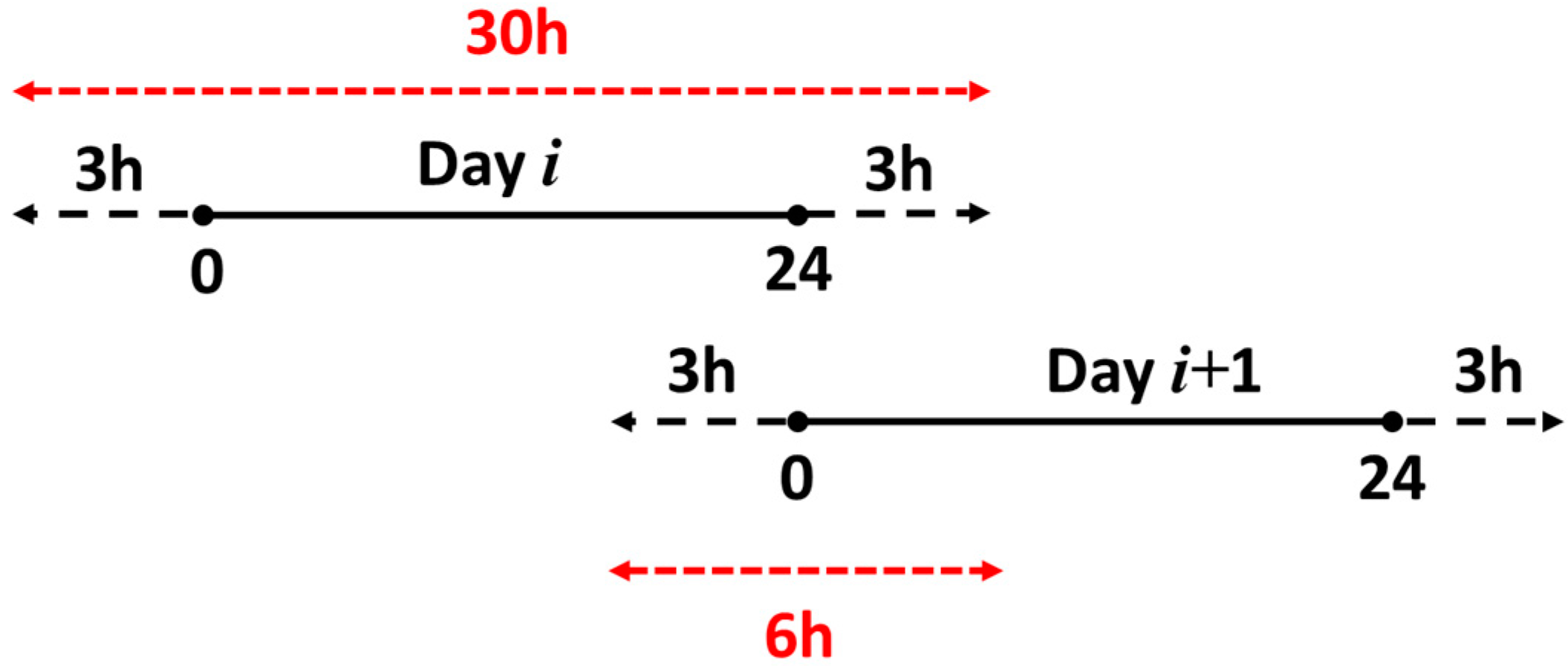
On the other hand, a 6 h overlap between two adjacent 30 h orbits is proposed to assess the orbit prediction overlap, as shown in
Figure 14. The daily estimated orbital parameters were used to propagate the orbit backward and forward for 3 h, respectively.
Figure 15 shows the RMS of the 6 h orbit overlap as a function of β angle for IIF and IIR.
Table 5 presents the statistic information of the 6 h orbit overlap. ECOM2 still had relatively large orbit errors, as compared to ECOM1 and ECOMC. Overall, the results of the 6 h overlap were relatively degraded as compared to those given in
Figure 13 and
Table 4. This is because having a longer arc overlap indicates that the orbit propagation error may be accumulated. Furthermore, the orbit error in the along-track direction accumulated faster than in the other two directions. This might be due to the fact that there is insufficient information for the orbit prediction in the satellite velocity direction (approximate to the along-track direction).
As a final remark, the IGS orbit is regarded as the pseudo-observation in the orbit fitting, suggesting that the accuracy of the reference orbit is mainly confined within the IGS orbit accuracy via the least-squares process. However, minimizing the difference between the resulting reference orbit and the IGS orbit is mainly for stabilizing the reference datum for more precise geodetic application. The ECOMC model greatly reduces the orbit model deficiencies in the cross-track direction, where the SLR may not effectively validate the outcome.
7. Impact of Reference Orbit on Precise Point Positioning
The GNSS orbit and clock information is essential for the PPP technique in connection to the conventional IGS-defined coordinate and time system. We assessed the impact of the reference orbit derived by the three ECOM-based models on PPP-derived station coordinates. The ionosphere-free linear combination of dual-frequency measurements was used for removing the first-order effect of ionosphere. Furthermore, the float phase ambiguity was estimated in this work. Here, the IGS final clock and the tracking data from an IGS station, ALIC from Australia, were used for this assessment. The daily estimated coordinates were compared to those from IGS weekly SINEX solutions.
Figure 16 shows the daily coordinate differences with respect to the IGS weekly solutions in 2018.
Table 6 shows the statistical information of the coordinate differences. ECOMC presented the smallest RMS difference, followed by ECOM1 and ECOM2. This result is consistent with
Table 2,
Table 4 and
Table 5, suggesting that the ECOM2 model shows relatively large uncertainty compared to ECOM1 and ECOMC. The improvement of the ECOMC solution over ECOM2 and ECOM1 was approximately 20% and 13%, respectively. Note that ECOM1 showed a ~5 mm disagreement with the IGS solution in the E direction. Furthermore,
Table 6 does not totally reflect the orbit difference of
Table 2. This is mainly because the station coordinate solution resulted from the least-squares adjustment, which allocated errors into different parameters which might be correlated.
In addition, we set up a test where a reference orbit directly from the IGS final orbit was used. Here, orbit fitting was not applied to this reference orbit, and a Lagrange function was only used for the orbit interpolation. As shown in
Table 6, the IGS solution presented a ~1 mm improvement over the ECOMC solution in the 3D RMS and reduced the bias in the east coordinate from the ECOM1 solution by 2.5 mm.
8. Conclusions
The objective of this study was to develop a hybrid ECOMC SRP model for GNSS orbit modeling using orbit fitting. The ECOMC model was assessed through parameter correlations, orbit differences with respect to pseudo-observations, orbit overlap, and PPP solutions. We show that the hybrid ECOMC performed relatively good fitting to the pseudo-observations as compared to ECOM1 and ECOM2. ECOMC is proposed for forming the GNSS reference orbit using the orbit fitting technique with the pseudo-observations. ECOMC resulted from a combination of the ECOM1 and ECOM2 parameterizations. In the correlation analysis of ECOMC parameters, the D0 estimation was sensitive to the 1 and 2 CPR terms, suggesting that ECOMC may compensate for the deficiencies of ECOM1 and ECOM2. For example, ECOM1 showed periodic variations in orbit difference with respect to the IGS final orbit, particularly for the IIR satellites. Such periodic variations were completely removed in the ECOM2 solution, which, however, showed large errors in the cross-track direction. These large errors were attributed to the fact that ECOM2 intrinsically lacks 1 CPR terms, which may stabilize the estimation of the 2 and 4 CPR terms in the satellite–Sun direction. The above mismodeling deficiencies from ECOM1 and ECOM2 were well handled by ECOMC.
On the other hand, the RMS of the orbit difference with respect to the IGS orbit was improved from ECOM2 to ECOMC by ~40%, ~10%, and ~50% in the radial, along-track, and cross-track directions, respectively. Additionally, the reference orbit derived by the different ECOM models was assessed through the orbit overlap at the day boundary. The orbit accuracy improvements of ECOMC over ECOM2 were 13.2%, 14.8%, and 42.6% for the IIF satellites and 7.4%, 7.7%, and 35.0% for the IIR satellites in the radial, along-track, and cross-track directions, respectively. This result shows that ECOMC greatly reduces the errors in the cross-track direction, where the SLR may not effectively validate the outcome. We also assessed the impact of the reference orbit derived by ECOM1, ECOM2, and ECOMC on PPP. The result showed that the improvement of the ECOMC solution over ECOM2 and ECOM1 was approximately 20% and 13%, respectively.


