Article

An Adaptive and Accurate Method for Rotational Angular Velocity Estimation of Rotor Targets via Fourier Coefficient Interpolation

National Key Laboratory of Science and Technology on Vessel Integrated Power System, Naval University of Engineering, Wuhan 430033, China
*
Author to whom correspondence should be addressed.
Remote Sens. 2022, 14(17), 4342; https://doi.org/10.3390/rs14174342
Submission received: 3 August 2022 / Revised: 27 August 2022 / Accepted: 29 August 2022 / Published: 1 September 2022

Abstract

:
As a special micro-motion feature of rotor targets, rotational angular velocity can provide a discriminant basis for target classification and recognition. In this paper, an adaptive and accurate method is proposed for estimating the rotational angular velocity of rotor targets via a Fourier coefficient interpolation algorithm that is based on modified frequency index residue initialization. The negative frequency complex exponential signal component is removed at each iteration to eliminate the estimation bias caused by spectrum superposition and improve the estimation accuracy. The frequency index residue initialization is modified, based on a normalized Fourier spectrum, to improve the estimable range of the rotational angular velocity and reduce the computational complexity of the algorithm. The simulation results show that the estimation performance of the proposed method achieves the Cramér–Rao lower bound and outperforms state-of-the-art methods in terms of the estimable range and estimation accuracy of the rotational angular velocity.

1. Introduction

The micro-motion parameters of rotor targets, such as rotational angular velocity, the number and length of rotor blades, Doppler peak value, and initial phase value provide important micro-Doppler information regarding the rotating parts. The effective and accurate estimation of micro-motion parameters, especially rotational angular velocity, is of great significance for classification and specific type identification [1].
In the echo model of rotor targets, the instantaneous Doppler frequency changes sinusoidally; the angular frequency of the real sinusoidal signal is the rotational angular velocity of rotor targets [2]. Therefore, an estimation of the rotational angular velocity of rotor targets can be transformed into an estimation of the angular frequency of the real sinusoidal signal, which is the most common and fundamental problem in the field of signal processing and has been the focus of many scholars in recent decades [3,4,5]. Generally, the angular frequency estimation of a real sinusoid can be divided into two categories: nonparametric estimation and parametric estimation. The nonparametric estimation method indirectly realizes the estimation of sinusoidal frequency by calculating the echo signal spectrum and searching for the spectrum peak. Typical research in this field includes the Capon algorithm [6], sinusoidal signal amplitude and phase estimation [7], and its adaptive and iterative method [8]. These algorithms have high-frequency resolution, but in order to obtain high parameter estimation accuracy, it is necessary to set a more refined spectrum grid when searching the spectrum peak, which brings high computational complexity. Even if the root mean square error (RMSE) [9] of parameter estimation reaches the Cramér–Rao lower bound (CRLB), the practical application of these algorithms is still restricted by their computational complexity. The parametric estimation method aims at elucidating the unknown frequency to realize its accurate estimation. According to the different processing domains of parameter estimation, the available methods can be divided into the time-domain estimation method and the frequency-domain estimation method. The time-domain estimation method directly focuses on the time-domain discrete waveform of the real sinusoid, while the frequency-domain estimation method further converts it to the frequency domain to realize the frequency estimation.
The typical time-domain estimation method for angular frequency can be divided into two categories. The first is the subspace algorithm, which realizes the estimation of angular frequency based on the orthogonality of signal subspace and noise subspace and on the characteristic that the signal guidance vector and echo signal form the same subspace [10]. Shahapurkar N. et al. [11] applied the multiple signal classification (MUSIC) [12,13] algorithm to realize the parameter estimation of multiple complex sinusoidal signals. Although the simulation results verify the effectiveness of the MUSIC algorithm in this application field, the frequency difference set in the simulation experiment is large, and the influence of frequency difference on parameter estimation accuracy is not analyzed. It should be pointed out that singular value decomposition and matrix inversion in subspace algorithms need a substantial amount of calculation, which is the disadvantage of these types of algorithms [14]. The second is iterative optimization algorithms, which include maximum likelihood estimation [15], iterative quadratic maximum likelihood estimation [16], weighted least-squares estimation [17], constrained weighted least-squares estimation [18], etc. These algorithms use different error criteria to estimate the angular frequency of the real sinusoid by iteratively reducing the error between the original signal and the reconstructed signal. In the iterative optimization algorithm, in order to obtain accurate sinusoidal frequency estimation results, the error threshold in different error criteria should be set to a value as small as possible, which will bring great computational complexity to the algorithm.
Unlike the time-domain estimation method, the frequency-domain estimation method of angular frequency is based on the interpolation of discrete Fourier transform (DFT) coefficients, which can be realized by a fast Fourier transform (FFT). The computational complexity of the algorithm is obviously low. Therefore, many experts and scholars have promoted and improved it in recent years. Based on the Fourier coefficient interpolation method, this iterative strategy is adopted to gradually approach the frequency truth value [19]. For example, Candan Ç. proposed an angular frequency method for estimating a complex sinusoidal signal, based on the sampled value of a three-point discrete Fourier transform [20], then added a deviation elimination step [21] on the basis of the sampled value method of a three-point discrete Fourier transform, which further improved the angular frequency estimation performance. However, due to the limited signal length, a spectrum leakage occurs, and the spectrum superposition between the positive and negative frequency complex exponential signal components seriously reduces the frequency estimation accuracy and the signal-to-noise ratio (SNR) threshold. To solve this problem, Chen et al. suppressed the sidelobe of the negative frequency complex exponential signal component by adding a Kaise window to the real sinusoidal signal [22], but the suppression of spectrum leakage is limited and does not solve the problem of estimation bias caused by spectrum superposition. In [23], the rough estimation of frequency is first estimated, then the removing modulation frequency and filtering DC component are processed to eliminate the influence of the negative frequency complex exponential signal component on parameter estimation accuracy. However, this algorithm not only has the problem of error transmission but also fails when the angular frequency is low. In addition, Ye et al. [24,25] proposed a fast and accurate estimation method of angular frequency in a sinusoidal signal or multi-component complex exponential signal. This method filters out the negative frequency complex exponential signal component when obtaining the Fourier spectrum through a Fourier coefficient interpolation, but the initialization of parameters in this iterative strategy is not optimized, resulting in a reduction in the estimable range of angular frequency and the high computational complexity of the algorithm.
In this paper, we propose a novel Fourier coefficient interpolation algorithm based on modified frequency index residue initialization (MFIRI-FCI) to estimate the rotational angular velocity of rotor targets. The contributions of this paper can be summarized as follows. On the one hand, the mathematical model of the adaptive, iterative, and accurate estimation of rotational angular velocity, based on time-frequency analysis and angular frequency estimation of the sinusoidal signal, is derived and established. On the other hand, in order to eliminate the estimation bias caused by spectrum superposition, the negative frequency complex exponential signal component is filtered out in each iteration. Therefore, the estimation accuracy of the rotational angular velocity is improved, and the threshold of the signal-to-noise ratio is reduced. In addition, a novel initialization method of frequency index residue based on a normalized Fourier spectrum is proposed. By optimizing the initialization value of the frequency index residue, the estimable range of rotational angular velocity is improved and the computational complexity of the algorithm is effectively reduced.
The rest of this paper is organized as follows. The signal model of rotor targets is established in Section 2. The proposed rotational angular velocity estimation method, based on the MFIRI-FCI algorithm, is derived and summarized in Section 3. Section 4 verifies the effectiveness of the proposed method by simulated experiments. Our conclusions are presented in Section 5.

2. Signal Model

Take the helicopter as an example; the special geometry between the radar and a helicopter is shown in Figure 1a, in which the distance between the radar and the rotor target center is denoted as R C , and the angle of pitch is denoted as β . Considering the two-dimensional slant-range plane, the simplified geometry is shown in Figure 1b. A radar coordinate system X O Y and target coordinate system X O Y are set up, in which the rotor center is denoted as O . The rotation radius of the scatterer F on the rotor blade is assumed to be r—i.e., the distance from F to O is r —and the distance from F to the radar is denoted as R F . The scatterer F rotates around the target coordinate system center O with a rotational angular velocity ω 0 , and the rotation angle at the initial time is denoted as θ 0 . It is assumed that the radial velocity of the helicopter’s translational motion is v .
Considering the far field condition [26], the instantaneous distance between the scatterer F and the radar can be written as:
R F ( t m ) R C + v t m + r cos ( ω 0 t m + θ 0 )
where t m = m T r is the slow time, m denotes the m-th echo pulse, and T r is the pulse repetition interval.
In this paper, we take the linear frequency modulation (LFM) as the transmitted signal, which can be expressed as:
s t ( t ^ , t m ) = rect ( t ^ / T p ) exp ( j 2 π ( f c t + μ t ^ 2 / 2 ) )
where rect ( ) is the rectangular window function, t ^ is the fast time, T p is the pulse width, f c is the signal carrier frequency, μ is the chirp rate, and t = t ^ + t m is the total time. There are two different time variables, t ^ and t , in the transmitted signal described in Equation (2). The reason for this is that the signal carrier frequency, f c , exists on the whole pulse transmission time axis, while the chirp rate, μ , is used to adjust the change of Doppler frequency within a pulse. The echo signal of the scatterer, F , can be expressed as:
s r ( t ^ , t m ) = σ rect ( t m / T a ) rect ( ( t ^ 2 R F ( t m ) / c ) / T p )                                     exp ( j 2 π ( f c ( t 2 R F ( t m ) / c ) + μ ( t ^ 2 R F ( t m ) / c ) 2 / 2 ) )
where σ is the scattering coefficient of the scatterer F , T a is the observation time, and c is the speed of light. The target echo signal after pulse compression can be expressed as:
s F ( t ^ , t m ) = σ T p sin c ( B ( t ^ 2 R F ( t m ) / c ) ) rect ( t m / T a ) exp ( j 4 π R C / λ )                                     exp ( j 4 π ( v t m + r cos ( ω 0 t m + θ 0 ) ) / λ ) + w ( t ^ , t m )
where B is the signal bandwidth, λ is the wavelength, and w ( t ^ , t m ) denotes the white Gaussian noise signal. By taking the derivative of the phase, the micro-Doppler frequency can be obtained as:
f d F = 1 2 π d [ 4 π ( v t m + r cos ( ω 0 t m + θ 0 ) ) / λ ] d t m = 2 ( v ω 0 r sin ( ω 0 t m + θ 0 ) ) / λ
It can be seen from the above equation that the instantaneous Doppler frequency of the scatterer echo on rotor blades is related not only to the radial velocity v of the translational motion but also to the rotational angular velocity, ω 0 , of the rotating part and the rotating radius, r , of the scatterer. Moreover, after translational compensation, the instantaneous Doppler frequency of the scatterer on rotor blades changes as a sinusoidal signal, and the angular frequency of the sinusoidal signal is the rotational angular velocity of rotor blades.

3. Proposed Method

In the rotational angular velocity estimation method proposed in this paper, firstly, the instantaneous Doppler frequency of the rotor blade is estimated using the time-frequency analysis method. Secondly, on the basis of that estimation, the instantaneous Doppler frequency changes sinusoidally, while the angular frequency yields the rotational angular velocity; the angular frequency estimation of the sinusoidal signal is mainly studied and a Fourier coefficient interpolation algorithm, based on modified frequency index residue initialization (MFIRI-FCI), is proposed for rotational angular velocity estimation. In this section, we formulate the proposed rotational angular velocity estimation method, derive the iterative solution of the frequency index residue, and optimize the initialization method for parameters.

3.1. Instantaneous Doppler Frequency Estimation through Time-Frequency Analysis

After translational compensation, the echo of the range unit where the rotor target is located can be expressed as:
s F t m = a 0 exp ( j 4 π r cos ( ω 0 t m + θ 0 ) / λ ) + w t m
where a 0 denotes the amplitude constant, and a 0 = σ T p rect ( t m / T a ) exp ( j 4 π R C / λ ) . The vector form of Equation (6) can be rewritten as:
s F ( m ) = a 0 exp ( j 4 π r cos ( ω 0 m Δ t + θ 0 ) / λ ) + w ( m )
where a 0 = σ T p rect ( m Δ t / T a ) exp ( j 4 π R C / λ ) .
Taking the short-time Fourier transform (STFT) as an example, the time-frequency spectrum of the target echo can be expressed as:
S F ( m , k ) = STFT { s F ( n ) } = n = + s F ( n ) D ( n m ) exp ( j 2 π n k / N )
where S F ( m , k ) denotes the time-frequency spectrum, D ( n ) is the discrete window function, N is the number of sampling points in the window function, k is the discrete frequency sampling point, and k = N f / f s , where f and f s denote the Doppler frequency and sampling frequency, respectively.
Therefore, the instantaneous Doppler frequency of the rotor target can be obtained via:
s ( m ) = arg max m | S F ( m ,         k ) | 2 , k = 1 , 2 , , M
where s ( m ) denotes the instantaneous Doppler frequency of the rotor target.

3.2. Rotational Angular Velocity Estimation via Fourier Coefficient Interpolation

The instantaneous Doppler frequency obtained by STFT changes sinusoidally, which can be described as a real sinusoid in terms of additive, white, Gaussian noise (AWGN), and can be rewritten as:
x ( m ) = s ( m ) + w ( m ) = b 0 sin ( ω 0 m Δ t + θ 0 ) + w ( m )
where x ( m ) is the measured signal, s ( m ) is the real sinusoid signal, w ( m ) represents zero mean Gaussian white noise, b 0 , ω 0 , and θ 0 denote the amplitude, angular frequency and phase angle of the real sinusoid respectively, m is the index of the signal sampling point, and m 0 1 M 1 , Δ t establishes the sampling interval.
According to Euler’s formula, Equation (10) can be rewritten as:
x ( m ) = s 0 ( m ) + s 0 * ( m ) + w ( m )
where s 0 ( m ) represents the positive frequency complex exponential signal component, which can be expressed as:
s 0 ( m ) = b 0 2 exp ( j ( ω 0 m Δ t + θ 0 π 2 ) )
where ( ) represents the conjugate operation.
The estimation method of the angular frequency of real or complex sinusoidal signals, based on a fast Fourier transform, needs to determine the frequency index m 0 of the positive frequency complex exponential signal component, that is, to determine the peak index of the Fourier spectrum. This process can be described as:
F x ( l ) = FFT ( x ( m ) )
m 0 = arg max 0 l M / 2 | F x ( l ) | 2
It can be summarized that the angular velocity of the positive frequency complex exponential signal component can be obtained by:
ω 0 = 2 π f r m 0 + δ ω 0 M
where δ ω 0 represents the frequency index residue, and δ ω 0 [ 0.5 , 0.5 ] , f r represents the pulse repetition frequency of the radar system.
If there is only one complex exponential signal component in the signal to be estimated, then δ ω 0 = 0 , and the rotational angular velocity estimated by Equation (14) is accurate. However, when more than one complex exponential signal component exists in the signal, there is not only the problem of spectrum leakage but also the way that the spectrum superposition of each complex exponential signal component affects each one, resulting in the shift of the Fourier spectrum peak of the complex exponential signal component from the real peak. Therefore, the frequency index estimated by the FFT or DFT method is no longer accurate, and it is necessary to correct the frequency index using Equation (15). Thus, the problem of the precise estimation of rotational angular velocity is transformed into the problem of the estimation of frequency index residue, which will be achieved by iterative updates.
If we suppose that δ ^ ω 0 ( i 1 ) represents the estimated value of frequency index residue δ ω 0 at the ( i 1 ) - th iteration. At i - th iteration, the Fourier coefficient interpolation of measured signal x ( m ) at the position of m 0 + δ ^ ω 0 ( i 1 ) + δ 0 can be calculated and recorded as X δ 0 , and its mathematical expression is:
X δ 0 = 1 M m = 0 M 1 [ s 0 ( m ) + s 0 * ( m ) ] exp ( j 2 π M ( m 0 + δ ^ ω 0 ( i 1 ) + δ 0 ) m )
where the constant δ 0 is δ 0 = ± 0.5 .
By the substitution of Equations (12) and (15) into Equation (16), this can be converted to:
X δ 0 = B 0 M 1 + exp ( j 2 π ( δ ^ ω 0 ( i ) δ ^ ω 0 ( i 1 ) ) ) 1 exp ( j 2 π M ( δ ^ ω 0 ( i ) δ ^ ω 0 ( i 1 ) δ 0 ) ) + B 0 M 1 + exp ( j 2 π ( δ ^ ω 0 ( i ) + δ ^ ω 0 ( i 1 ) ) ) 1 exp ( j 2 π M ( 2 m 0 + δ ^ ω 0 ( i ) + δ ^ ω 0 ( i 1 ) + δ 0 ) )             = S δ 0 + L δ 0
where δ ^ ω 0 ( i ) represents the estimated value of the frequency index residue δ ω 0 at the iteration. B 0 is an unknown constant and B 0 = b 0 2 exp ( j ( θ 0 π 2 ) ) . S δ 0 and L δ 0 represent the Fourier coefficient interpolation of the positive frequency complex exponential signal component and negative frequency complex exponential signal component at the position of m 0 + δ ^ ω 0 ( i 1 ) + δ 0 , respectively. Assuming that the variation of frequency index residue Δ δ ω 0 in two adjacent iterations meets Δ δ ω 0 = δ ^ ω 0 ( i ) δ ^ ω 0 ( i 1 ) , therefore, S δ 0 can be expressed as:
S δ 0 = B 0 M 1 + exp ( j 2 π Δ δ ω 0 ) 1 exp ( j 2 π M ( Δ δ ω 0 δ 0 ) ) .
If Δ δ ω 0 δ 0 M , according to the Taylor expansion formula, it can be established that:
1 exp ( j 2 π M ( Δ δ ω 0 δ 0 ) ) j 2 π ( Δ δ ω 0 δ 0 ) / M .
Thus, Equation (18) can be rewritten as:
S δ 0 = b Δ δ ω 0 Δ δ ω 0 δ 0
where b = B 0 1 + exp ( j 2 π Δ δ ω 0 ) j 2 π Δ δ ω 0 . In order to establish the variation of the frequency index residue, Equation (20) can be converted to:
S 0.5 + S 0.5 S 0.5 S 0.5 = 2 Δ δ ω 0 .
The variation of the frequency index residue Δ δ ω 0 can be calculated as:
Δ δ ω 0 = δ ^ ω 0 ( i ) δ ^ ω 0 ( i 1 ) = 1 2 S 0.5 + S 0.5 S 0.5 S 0.5 .
Thus, according to the initialization value of the frequency index residue δ ^ ω 0 ( 0 ) , and through a step-by-step iterative operation, the frequency index residue at the i - th iteration can be updated to:
δ ^ ω 0 ( i ) = δ ^ ω 0 ( i 1 ) + 1 2 S 0.5 + S 0.5 S 0.5 S 0.5 .
Additionally, in order to reduce the influence of noise on parameter estimation, Equation (23) can be modified as:
δ ^ ω 0 ( i ) = δ ^ ω 0 ( i 1 ) + 1 2 Re { S 0.5 + S 0.5 S 0.5 S 0.5 }
where Re {●} represents the real part.
According to the frequency index residual δ ^ ω 0 ( i ) obtained from the current iterative estimation, the Fourier coefficient interpolations of the sinusoidal signal and negative frequency complex exponential signal components at the position of m 0 + δ ^ ω 0 ( i ) are calculated, respectively, and the estimation of the unknown constant term B ^ 0 ( i ) can be updated by subtracting two interpolations, which can be expressed as:
B ^ 0 ( i ) = 1 M m = 0 M 1 x ( m ) exp ( j 2 π M ( m 0 + δ ^ ω 0 ( i ) ) m ) ( B ^ 0 ( i 1 ) ) M 1 exp ( j 4 π δ ^ ω 0 ( i ) ) 1 exp ( j 4 π M ( m 0 + δ ^ ω 0 ( i ) ) ) .
To sum up, the flow of the rotational angular velocity estimation method, based on Fourier coefficient interpolation, is as follows:
Step 1: Estimate the frequency index m 0 according to Equations (13) and (14).
Step 2: Initialize the iteration order, where, the frequency index residue δ ^ ω 0 ( 0 ) = 0 , the unknown constant B ^ 0 ( 0 ) = 0 , and determine the estimation accuracy ε 0 .
Step 3: Update the Fourier coefficient interpolation of the sinusoidal signal X δ 0 = 1 M m = 0 M 1 x ( m ) exp ( j 2 π M ( m 0 + δ ^ ω 0 ( i 1 ) + δ 0 ) m ) with δ 0 = ± 0.5 .
Step 4: Update the Fourier coefficient interpolation of the negative frequency complex exponential signal component, L δ 0 = ( B ^ 0 ( i 1 ) ) M 1 + exp ( j 4 π δ ^ ω 0 ( i 1 ) ) 1 exp ( j 2 π M ( 2 m 0 + 2 δ ^ ω 0 ( i 1 ) + δ 0 ) ) .
Step 5: Update the Fourier coefficient interpolation of the positive frequency complex exponential signal component, according to the results of step 3 and step 4, as S δ 0 = X δ 0 L δ 0 .
Step 6: Update the frequency index residue δ ^ ω 0 ( i ) and the unknown constant B ^ 0 ( i ) according to Equations (24) and (25), and update the rotational angular velocity ω ^ 0 ( i ) = 2 π f r m 0 + δ ^ ω 0 ( i ) M at the i - th iteration.
Step 7: Judge whether the iteration termination condition is true | ω ^ 0 ( i ) ω ^ 0 ( i 1 ) | ε 0 ; if not, update the iteration order as i = i + 1 , and then return to Step 3 to continue. Otherwise, the iterative estimation process is terminated, and the precise estimation value of rotational angular velocity is ω ^ 0 = ω ^ 0 ( i ) .

3.3. Initialization of the Frequency Index Residue, Based on a Normalized Fourier Spectrum

In the Fourier coefficient interpolation method described above, the estimation of rotational angular velocity is a process from coarse to fine, and it is achieved indirectly by iteratively estimating the frequency index residue, where the frequency index residue δ ^ ω 0 ( 0 ) and the unknown constant B ^ 0 ( 0 ) are both initialized to 0. Therefore, at the first iteration, the Fourier coefficient interpolation of the sinusoidal signal can be calculated as:
X δ 0 = 1 M m = 0 M 1 x ( m ) exp ( j 2 π M ( m 0 + δ 0 ) m ) ,         δ 0 = ± 0.5 .
According to Equation (15) and the above analysis, if m 0 + δ ω 0 < 0.5 or ω 0 < π f r / M , the frequency index will be calculated as m 0 = 0 , and Equation (26) can be modified as:
X δ 0 = 1 M m = 0 M 1 x ( m ) exp ( j 2 π M δ 0 m ) ,         δ 0 = ± 0.5 .
It is easy to conclude that Equation (27) represents the Fourier coefficient interpolation of the sinusoidal signal x ( m ) at the positions of ± 0.5 , which can also be understood as the discrete Fourier transform spectrum value of the sinusoidal signal at locations ± 0.5 . According to the conjugate symmetry of the discrete Fourier transform of the real signal, X 0.5 and X 0.5 are conjugated, which can be expressed as:
X 0.5 = X 0.5 .
In addition, because the initialization of the unknown constant is B ^ 0 ( 0 ) = 0 , the Fourier coefficient interpolation of negative frequency complex exponential signal components at the first iteration can be calculated according to Equation (17) as:
L 0.5 = L 0.5 = 0 .
Therefore, the Fourier coefficient interpolation of the positive frequency complex exponential signal component at the position of ± 0.5 is also conjugated; that is:
S 0.5 = S 0.5 .
The frequency index residue can be updated as:
δ ^ ω 0 ( 1 ) = δ ^ ω 0 ( 0 ) + 1 2 Re { S 0.5 + S 0.5 S 0.5 S 0.5 } = 0 .
According to the initialization of the frequency index m 0 = 0 and Equations (25) and (31), the unknown constant can be updated as:
B ^ 0 ( 1 ) = 1 M m = 0 M 1 x ( m ) exp ( j 2 π M ( m 0 + δ ^ ω 0 ( 1 ) ) m ) ( B ^ 0 ( 0 ) ) M 1 exp ( j 4 π δ ^ ω 0 ( 1 ) ) 1 exp ( j 4 π M ( m 0 + δ ^ ω 0 ( 1 ) ) )
As we can see from Equation (32), the unknown constant B ^ 0 ( 1 ) at the first iteration will be infinity, so that the iterative estimation of the rotational angular velocity in the proposed algorithm ends here. In general, when the parameter initializations are set to δ ^ ω 0 ( 0 ) = 0 and B ^ 0 ( 0 ) = 0 , the rotational angular velocity estimation method based on Fourier coefficient interpolation that is proposed in this paper cannot realize the estimation of ω 0 < π f r / M . Theoretically, the threshold, ω 0 threshold , which is the lower limit of the estimable range of rotational angular velocity of the proposed method based on Fourier coefficient interpolation is:
ω 0 threshold = π f r / M .
For example, when the pulse repetition frequency f r is 5000 Hz , and the number of echo pulses, M , is 250, the threshold of the rotational angular velocity will be ω 0 threshold 62.83 rad / s . In practice, the rotational angular velocity of the rotor target is often lower than that above the threshold. On the basis of this finding, the current paper proposes a parameter initialization method that is based on the normalized Fourier spectrum. The main improvement is to use the frequency domain waveform of the sinusoidal signal to adaptively initialize the parameters of the frequency index residue, so as to reduce the rotational angular velocity threshold of the algorithm.
Theoretically, when the rotational angular velocity of the rotor target meets the ω 0 < ω 0 threshold , the Fourier spectrum peak of the instantaneous Doppler frequency of the rotor target should be at the position of m 0 + δ ω 0 = ω 0 M / ( 2 π f r ) , where 0 < ω 0 M / ( 2 π f r ) < 1 . However, due to the spectrum superposition between the positive and negative frequency complex exponential signal components, and the reason for the low Fourier transform resolution and spectrum leakage, the spectrum peak is located at the position of m 0 + δ ω 0 = 0 . As we know, the Fourier spectrum value of a certain frequency point in the amplitude of the normalized Fourier spectrum reflects its proportions in the whole Fourier spectrum. Thus, the normalized Fourier spectrum value of the latter frequency point at the frequency index, m 0 , is used to adaptively modify the initialization of the frequency index residue, which can be expressed as:
δ ^ ω 0 ( 0 ) = 2 | F x ( m 0 + 1 ) | k = 0 M / 2 | F x ( k ) |
where F x ( k ) represents the Fourier spectrum of the sinusoidal signal, calculated by Equation (13).

3.4. The Cramér–Rao Lower Bound of the Rotational Angular Velocity Estimation

The Cramér–Rao lower bound (CRLB) is an important criterion often used in parameter estimation algorithms to evaluate whether the estimator obtained by the algorithm is an unbiased estimator. It is the optimal performance lower bound by which to measure the estimation accuracy of an unbiased estimator. In order to evaluate the estimation performance of the method proposed in this paper and compare the advantages of the parameter estimation of various methods, the CRLB of the rotational angular velocity estimation is derived from the probability model of the instantaneous Doppler frequency of rotor targets.
Using Equation (10), the vector form of the instantaneous Doppler frequency of the target echo can be expressed as:
x = s + w
According to the maximum likelihood estimation (MLE) theory [27] and the Gaussian distribution model, the probability density function (PDF) of the observation matrix x can be expressed as:
p ( x ; υ ) = ( 1 2 π σ 0 2 ) M exp ( 1 2 σ 0 2 m = 0 M ( x ( m ) s ˜ ( m ) ) 2 )
where p ( x ; υ ) represents the probability density function of the observation matrix x corresponding to the parameter vector υ = [ b , ω , θ ] T , and b , ω and θ represent the signal amplitude, rotational angular velocity, and initial phase angle to be estimated in the sinusoidal signal parameters, respectively. σ 0 2 represents the noise variance of Gaussian white noise, s ˜ ( m ) indicates the signal to be estimated, and s ˜ ( m ) = b sin ( ω m Δ t + θ ) .
The CRLB of the parameter vector, υ , is the element on the main diagonal of the inverse matrix of the corresponding Fisher information matrix (FIM). The FIM obtained from the probability density function of Equation (36) is:
J = E ( ( ln p ( x ; υ ) υ ) 2 ) = E ( 2 ln p ( x ; υ ) υ 2 )
where E ( · ) is the expectation. The main diagonal element of the FIM can be obtained by substituting Equation (36) into Equation (37) as:
J 11 = E ( 2 ln p ( x ; υ ) b 2 ) = 1 σ 0 2 m = 0 M 1 sin 2 ( ω 0 m Δ t + θ 0 )
J 22 = E ( 2 ln p ( x ; υ ) ω 2 ) = b 0 2 Δ t 2 σ 0 2 m = 0 M 1 m 2 cos 2 ( ω m Δ t + θ 0 )
J 33 = E ( 2 ln p ( x ; υ ) θ 2 ) = b 0 2 σ 0 2 m = 0 M 1 cos 2 ( ω 0 m Δ t + θ ) .
Therefore, the CRLB of rotational angular velocity ω can be expressed as:
CRLB ω = σ 0 2 b 0 2 Δ t 2 m = 0 M 1 m 2 cos 2 ( ω m Δ t + θ 0 )
It can be seen from Equation (41) that the CRLB of rotational angular velocity is not only related to the SNR but also related to its own value. The reason for this is that the sinusoidal signal is expanded into two complex exponential signal components with opposite frequencies, through the Euler formula. The rotational angular velocity can affect the position of the peak value of the positive and negative complex exponential signal components of frequencies in the frequency domain. The closer the two are, the more serious the spectrum superposition between them, resulting in the lower performance of parameter estimation. Because cos 2 ( ω m Δ t + θ 0 ) 1 , the CRLB of the rotational angle velocity in Equation (41) can be approximately expressed as:
CRLB ω = σ 0 2 b 0 2 Δ t 2 m = 0 M 1 m 2 cos 2 ( ω m Δ t + θ 0 ) 6 σ 0 2 b 0 2 Δ t 2 M ( M 1 ) ( 2 M 1 ) .

4. Experimental Results

In this section, we illustrate the effectiveness and validation of the modified frequency index residue initialization algorithm and the performance of the threshold of SNR and the rotational angular velocity with simulated data. We consider that a monostatic early-warning radar and the micro-Doppler signals can be simulated by the rotation of the rotor blades in a helicopter. The main parameters of the transmitted signal are summarized in Table 1.

4.1. Effectiveness Validation of Parameter Initialization

This experiment verifies the parameter initialization of the frequency index residue, based on the normalized Fourier spectrum with a noise-free background, and compares the number of iterations required by the algorithm with the filtering negative frequency complex exponential signal components-based Fourier coefficient interpolation method (FNFC-FCI) detailed by the authors of [24]. It should be noted that the algorithm given in [24] always initializes the parameter of the frequency index residue as zero.
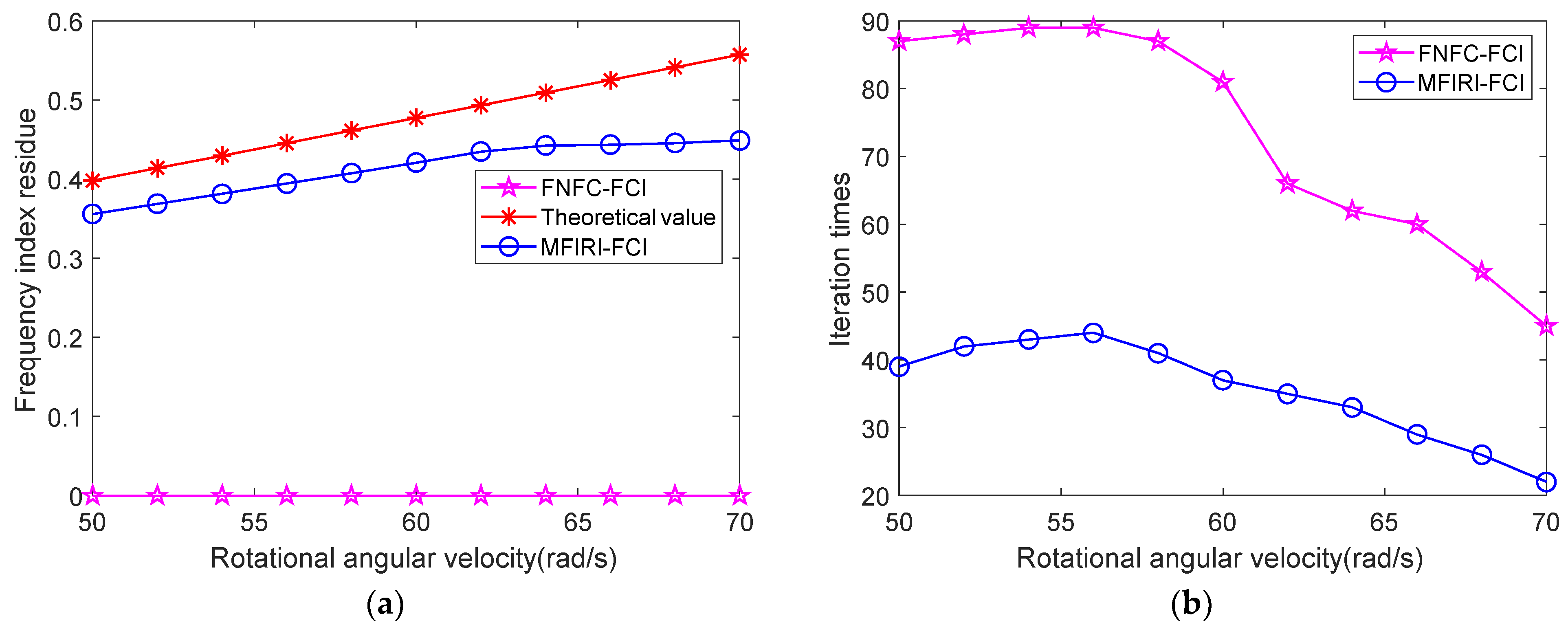
Figure 2 shows the comparison results of the initialization values and iteration times of the frequency index residue of different algorithms, in which the estimation accuracy of the rotational angular velocity is set as ε 0 = 0.1 rad / s , the theoretical value of the frequency index residue is calculated by Equation (15), and the proposed Fourier coefficient interpolation method, based on the modified frequency index residue initialization, is recorded as MFIRI-FCI. According to the analysis in Section 3.3, the theoretical value of the rotational angular velocity threshold, which represents the minimum value of rotational angular velocity that can be estimated by the algorithm, is 62.83 rad / s under the experimental parameter setting; however, due to the spectrum superposition between the positive and negative frequency complex exponential signal components, the practical value of the rotational angular velocity threshold becomes 46 rad / s . Since the algorithm given in [24] cannot estimate the rotational angular velocity by iteration when its true value is less than the theoretical value of the rotational angular velocity threshold, Figure 2 shows the comparison results when the rotational angular velocity changes from 50 rad/s to 70 rad/s. At this time, the frequency index is m 0 = 1 .
It can be concluded from Figure 2a that compared with the frequency index residue in the FNFC-FCI algorithm, the initialization value of the frequency index residue, based on the proposed normalized Fourier spectrum method, corresponds to the true value of the rotational angular velocity taken one by one, because the initialization value of the frequency index residue changes with the rotational angular velocity and is closer to the theoretical value. From Figure 2b, it can be seen that the FNFC-FCI algorithm requires more iteration times to reach the set accuracy of rotational angular velocity estimation, which shows that the closer the initialization value of the frequency index residue is to the theoretical value, the lower the computational complexity of the algorithm, thus verifying the effectiveness of a parameter initialization method based on the normalized Fourier spectrum method that is proposed in this paper.

4.2. Comparative Analysis of the Estimation Error of Rotational Angular Velocity

This experiment illustrates the effectiveness of the proposed rotational angular velocity estimation method based on the MFIRI-FCI algorithm, from the two aspects of signal-to-noise ratio threshold and rotational angular velocity threshold under the background of Gaussian white noise, and compares it with existing state-of-the-art methods, i.e., the MUSIC algorithm [12,13], weighted extended MUSIC algorithm [11,26], the Fourier coefficient interpolation method based on dichotomous search (Search-FCI) [28,29], the iterative Fourier coefficient interpolation method (Iteration-FCI) [19], the three-point function value method (TPF) [20,21], a Fourier coefficient interpolation algorithm based on filtering negative frequency complex exponential signal components (FNFC-FCI) [24,25], and the Cramér–Rao lower bound. It should be pointed out that the CRLB of the rotational angular velocity is given according to Equation (42).

4.2.1. Comparative Analysis of Signal-to-Noise Ratio Threshold

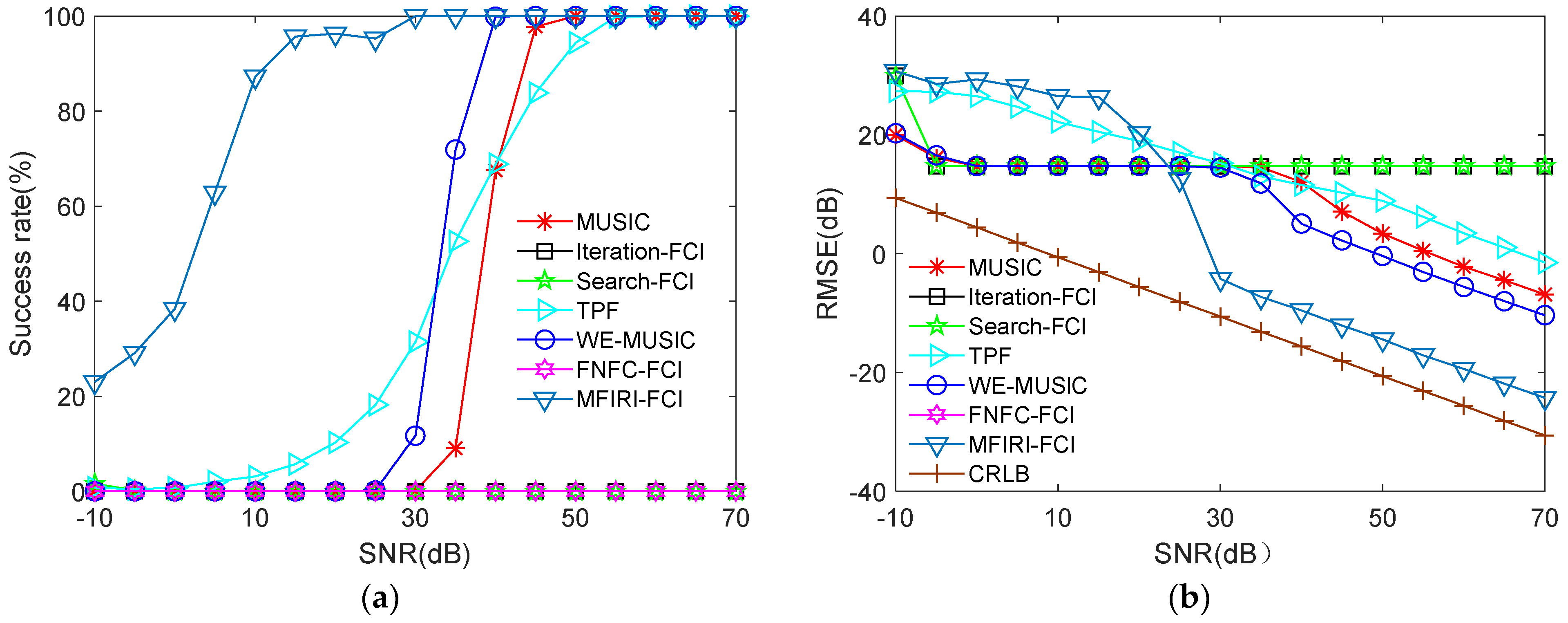
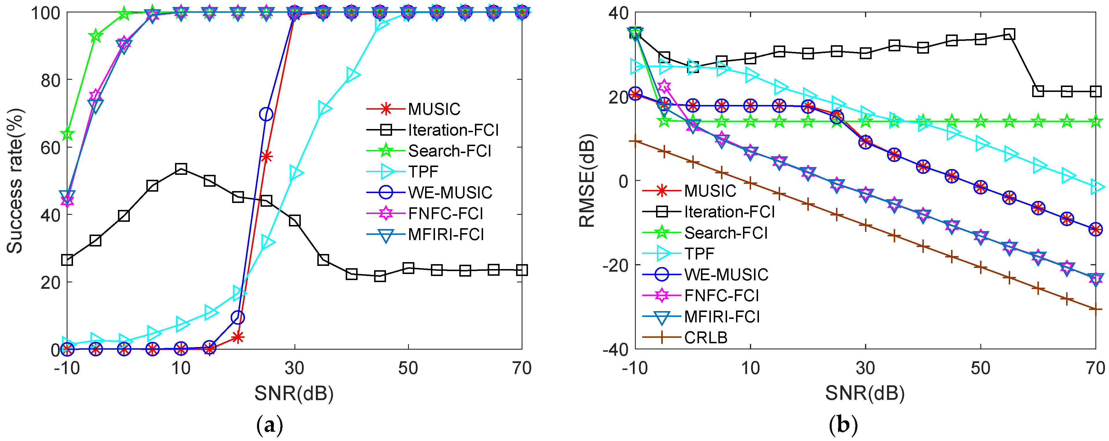
In order to compare and analyze the SNR threshold of the algorithm, a Monte Carlo experiment is designed and the simulation parameters are set as: pulse repetition frequency f r = 5000 Hz , observation time T a = 0.05 s , number of trails N trails = 1000 , and the SNR changes from -10db to 80dB at 5dB intervals. Figure 3, Figure 4 and Figure 5 show the success rate and root mean square error (RMSE) of the rotational angular velocity estimation of different algorithms when the rotational angular velocity is 30rad/s, 60rad/s, and 90rad/s, respectively. The judgment rule of successful estimation is that the absolute estimation error of rotational angular velocity is less than half of its true value, while the success rate of the estimation can be expressed as:
P n = i = 1 N t r a i l s sgn ( | ω 0 ω ^ 0 i | < ω 0 / 2 ) / N t r a i l s
where ω ^ 0 i denotes the estimated value of the rotational angular velocity at the i - th trail, and sgn ( ) represents the sign function, which can be expressed as:
sgn ( | ω 0 ω ^ 0 i | < ω 0 / 2 ) = { 1   | ω 0 ω ^ 0 i | < ω 0 / 2 0   | ω 0 ω ^ 0 i | < ω 0 / 2
It can be seen from Figure 3 that when the rotational angular velocity is 30 rad/s, firstly, the success rate of the Search-FCI and Iteration-FCI algorithms for the estimation of rotational angular velocity is 0, and the RMSE is also 0, which indicates that these two algorithms have failed in terms of parameter setting. The reason for this is that their low frequency resolution leads to an estimated rotational angular velocity of 0 rad/s. Secondly, although the MUSIC algorithm, TPF algorithm, and GSS-WE-MUSIC algorithm can effectively estimate the rotational angular velocity when the SNR is high, the RMSE is much higher than CRLB. Then, according to the experimental results in Section 4.1, the FNFC-FCI algorithm can no longer realize the iterative estimation when the rotational angular velocity is less than 46 rad/s. This conclusion is correspondingly reflected in Figure 3; specifically, the success rate of the rotational angular velocity estimation is zero, and there is no RMSE value. Finally, compared with the above comparison algorithms, the proposed MFIRI-FCI algorithm still has a high estimation success rate when the SNR is low, while the RMSE value is close to CRLB when the SNR is high, and the SNR threshold is about 30 dB.
In Figure 4, the parameter of rotational angular velocity is set as 60 rad/s. Although the estimation success rate of the Search-FCI algorithm and the Iteration-FCI algorithm has been improved, the parameter estimation performance of these algorithms is still limited by their low frequency resolution. At this point in time, the true value of the rotational angular velocity is higher than the theoretical value of the rotational angular velocity threshold used in the FNFC-FCI algorithm. The success rate and RMSE of the rotational angular velocity estimation of the FNFC-FCI algorithm are equivalent to those of the algorithm proposed in this paper; however, when the SNR is lower than 0 dB, its estimation accuracy is reduced. Compared with other comparison algorithms, the proposed MFIRI-FCI algorithm has the highest estimation success rate and the lowest RMSE of the rotation angular velocity estimation methods. Compared with the experimental results in Figure 4, the threshold of SNR is also reduced to 0 dB.
Compared with the simulation results in Figure 3 and Figure 4, the rotational angular velocity in Figure 5 is set as 90 rad/s. The comparative results show that the estimation success rate and RMSE of the MUSIC algorithm, GSS-WE-MUSIC algorithm, and TPF algorithm change little, but there is still a large gap, compared with CRLB. The estimation performance of the Search-FCI algorithm and Iteration-FCI algorithm has been significantly improved; the main reason for this is that the larger the rotational angular velocity, the smaller the spectrum superposition between the positive and negative frequency complex exponential signal components; therefore, the higher the estimation success rate, the smaller the RMSE value. Under this parameter setting, although the two algorithms have a high estimation accuracy when the SNR is low, the RMSE value does not gradually approach the CRLB and tends to be stable due to the limitations of the frequency resolution and search step size of the algorithm itself. The proposed MFIRI-FCI algorithm has obvious advantages in terms of the success rate and RMSE of rotational angular velocity estimation.

4.2.2. Comparative Analysis of the Rotational Angular Velocity Threshold

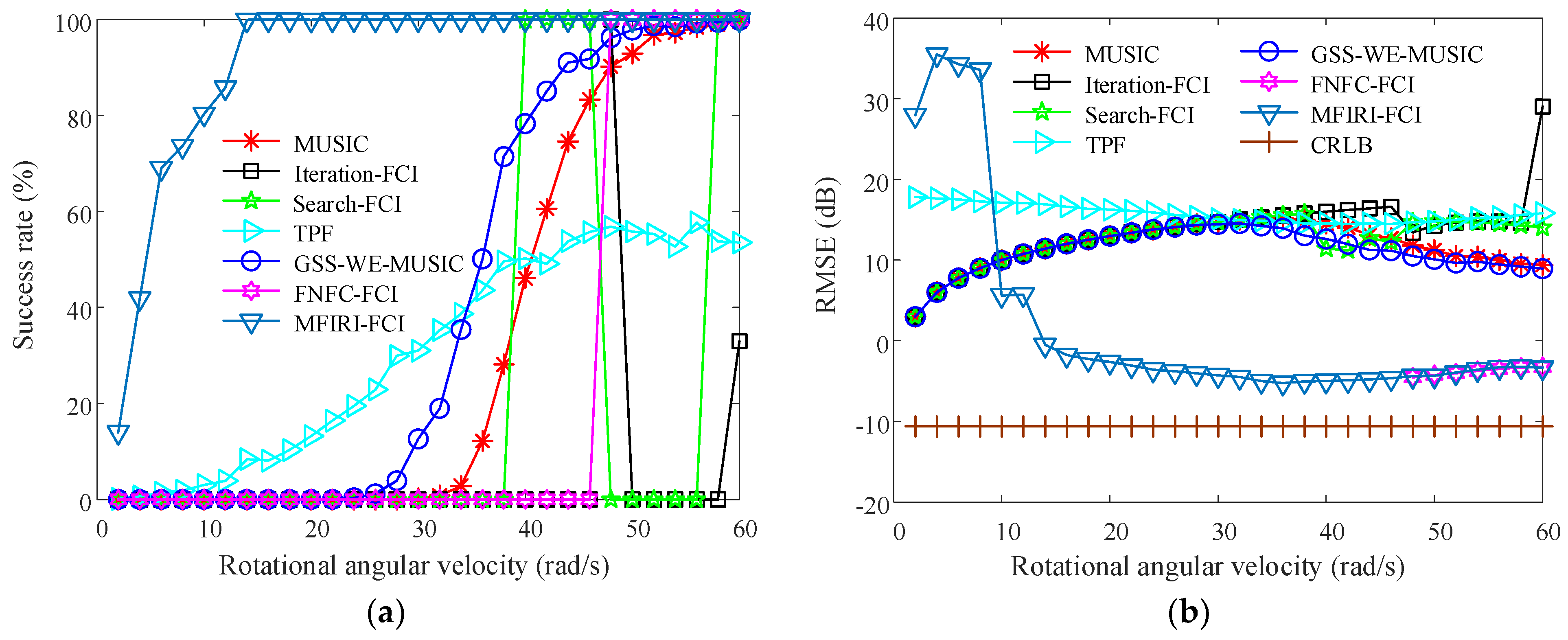
In order to compare and analyze the rotational angular velocity threshold of the algorithm, a Monte Carlo experiment was designed; the simulation parameter settings are the same as those used in Section 4.2.1. Figure 6 and Figure 7 show the experimental results of the different algorithms when the SNR is 30 dB and 60 dB, respectively, whereby the rotational angular velocity changes from 2 rad/s to 60 rad/s in steps of 2 rads/s.
Comparing the simulation results in Figure 6 and Figure 7, firstly, it can be seen that with the increase in rotational angular velocity, the RMSE of the Search-FCI algorithm, Iteration-FCI algorithm, MUSIC algorithm, and GSS-WE-MUSIC algorithm first increases and then decreases. The increase in RMSE indicates that the algorithm cannot effectively estimate the rotational angular velocity, which can be drawn from the experimental results of the estimation success rate. In addition, the success rate of the rotational angular velocity estimation of the Search-FCI algorithm and Iteration-FCI algorithm fluctuates from 0 to 1, which is also related to the spectrum superposition between the positive and negative frequency complex exponential signal components. Secondly, the estimation success rate of the FNFC-FCI algorithm is zero when the rotational angular velocity is less than 46 rad/s and there is no RMSE value. When the rotational angular velocity is higher than 46 rad/s, the estimation success rate and RMSE value of the rotational angular velocity are equivalent to the MFIRI-FCI algorithm that is proposed in this paper. This verifies the correctness of the theoretical analysis of the rotational angular velocity threshold and the existence of the defect regarding a low rotational angular velocity threshold in the algorithm. Finally, compared with the FNFC-FCI algorithm, the proposed MFIRI-FCI algorithm initializes the frequency index residue by a normalized Fourier spectrum, and the rotational angular velocity threshold is significantly reduced.
To sum up, in the proposed MFIRI-FCI-based rotational angular velocity estimation algorithm, the estimation bias caused by spectrum superposition is eliminated by removing the negative frequency complex exponential signal component in the process of Fourier coefficient interpolation, which improves the estimation success rate and estimation accuracy and reduces the SNR threshold. Then, the frequency index residue is initialized, based on the normalized Fourier spectrum, which not only reduces the rotational angular velocity threshold but also decreases the computational complexity of the algorithm by reducing the number of iterations. In addition, the adaptive and iterative estimation of rotational angular velocity can be realized by circularly calculating the Fourier coefficient interpolation, thereby estimating the frequency index residue and the unknown constant term of the signal.

5. Conclusions

In this paper, we proposed an adaptive and accurate estimation method for calculating the rotational angular velocity of rotor targets via Fourier coefficient interpolation, based on modified frequency index residue initialization. The instantaneous Doppler frequency of the rotor target was first estimated with a time-frequency analysis method. Second, on the basis of that finding, the instantaneous Doppler frequency changed sinusoidally; the angular frequency is the rotational angular velocity, the Fourier coefficient interpolation method is utilized, and the negative frequency complex exponential signal component is removed at each iteration to improve the estimation accuracy of rotational angular velocity. Then, a modified algorithm based on a normalized Fourier spectrum is used to optimize the initialization of the frequency index residue to improve the estimable range of rotational angular velocity and reduce the computational complexity. The simulation results were presented to verify the effectiveness of the proposed method. These results show that the proposed method outperforms current state-of-the-art methods in terms of the estimable range and estimation accuracy of the rotational angular velocity, the threshold of SNR, and the computational complexity of the method.

Author Contributions

Writing—original draft preparation, W.W.; methodology, W.W. and J.M.; writing—review and editing, J.Z.; validation, H.W. All authors have read and agreed to the published version of the manuscript.

Funding

This work was supported in part by the National Science Fund for Distinguished Young Scholars by NSFC (No. 52025072), the Young Elite Scientists Sponsorship Program by CAST, the Foundation of National Key Laboratory of Science and Technology on Vessel Integrated Power System (No. 6142217210501), the National Natural Science Foundation of China (No. 61801502 and No. 61901514), and the National Key Research and Development Program.

Acknowledgments

The authors would like to thanks to the editor and anonymous reviewers for processing our manuscript.

Conflicts of Interest

The authors declare no conflict of interest.

References

  1. Wang, W.T.; Zhu, Y.; Tang, Z.Y.; Chen, Y.C.; Zhu, Z.B.; Sun, Y.J.; Zhou, C. Efficient rotational angular velocity estimation of rotor target via modified short-time fractional Fourier transform. Remote Sens. 2021, 13, 1970. [Google Scholar] [CrossRef]
  2. Li, G.; Varshney, P.K. Micro-Doppler parameter estimation via parametric sparse representation and pruned orthogonal matching pursuit. IEEE J. Sel. Top. Appl. Earth Obs. Remote Sens. 2014, 7, 4937–4948. [Google Scholar] [CrossRef]
  3. Wang, K.; Wen, H.; Tai, W.S.; Li, G.Q. Estimation of damping factor and signal frequency for damped sinusoidal signal by three points interpolated DFT. IEEE Signal Process. Lett. 2019, 16, 1927–1930. [Google Scholar] [CrossRef]
  4. Rao, V.; Gaddipati, P.; Rao, P. Signal-driven window-length adaptation for sinusoid detection in polyphonic music. IEEE Trans. Audio Speech Lang. Process. 2012, 20, 342–348. [Google Scholar] [CrossRef]
  5. Follum, J.; Pierre, J.W.; Martin, R. Simultaneous estimation of electromechanical modes and forced oscillations. IEEE Trans-Actions Power Syst. 2017, 32, 3958–3967. [Google Scholar] [CrossRef]
  6. Capon, J. High-resolution frequency-wavenumber spectrum analysis. Proc. IEEE 1969, 57, 1408–1418. [Google Scholar] [CrossRef]
  7. Li, J.; Stoica, P. An adaptive filtering approach to spectral estimation and SAR imaging. IEEE Trans. Signal Process. 1996, 44, 1469–1484. [Google Scholar] [CrossRef]
  8. Yardibi, T.; Li, J.; Stoica, P.; Xue, M.; Baggeroer, A.B. Source localization and sensing: A nonparametric iterative adaptive approach based on weighted least squares. IEEE Trans. Aerosp. Electron. Syst. 2010, 46, 425–443. [Google Scholar] [CrossRef]
  9. Xie, Y.Q.; Li, Y.S.; Gu, Y.T.; Cao, J.W.; Chen, B.D. Fixed-point minimum error entropy with fiducial points. IEEE Trans. Signal Process. 2020, 68, 3824–3833. [Google Scholar] [CrossRef]
  10. Naha, A.; Samanta, A.K.; Routray, A.; Deb, A.K. Determining autocorrelation matrix size and sampling frequency for MUSIC algorithm. IEEE Signal Process. Lett. 2015, 22, 1016–1020. [Google Scholar] [CrossRef]
  11. Shahapurkar, N.; Ramalingam, C.S. Threshold performance of MUSIC when using the forward-backward data matrix. IEEE Signal Process. Lett. 2006, 13, 80–83. [Google Scholar] [CrossRef]
  12. Liao, K.F.; Yu, Z.R.; Xie, N.B.; Jiang, J.Z. Joint estimation of azimuth and distance for far-field multi targets based on graph signal processing. Remote Sens. 2022, 14, 1110. [Google Scholar] [CrossRef]
  13. Wang, W.T.; Liu, S.X.; Shen, X.Z.; Zheng, W.J. 3D imaging algorithm of directional borehole radar based on root-MUSIC. Remote Sens. 2021, 13, 2957. [Google Scholar] [CrossRef]
  14. Liu, Z.X.; Quan, Y.H.; Wu, Y.J.; Xing, M.D. Super-resolution range and velocity estimation for SFA-OFDM radar. Remote Sens. 2022, 14, 278. [Google Scholar] [CrossRef]
  15. Liu, Y.; Sun, Y.X.; Xiong, Z.H. An approximate maximum likelihood estimator for instantaneous frequency estimation of multicomponent nonstationary signals. IEEE Trans. Instrum. Meas. 2022, 71, 6501509. [Google Scholar] [CrossRef]
  16. Bresler, Y.; Macovski, A. Exact maximum likelihood parameter estimation of superimposed exponential signals in noise. IEEE Trans. Acoust. Speech Signal Process. 1986, 34, 1081–1089. [Google Scholar] [CrossRef]
  17. Chan, F.K.W.; So, H.C.; Lau, W.H.; Chan, C.F. Efficient approach for sinusoidal frequency estimation of gapped data. IEEE Signal Process. Lett. 2010, 17, 611–614. [Google Scholar] [CrossRef]
  18. So, H.C.; Chan, K.W.; Chan, Y.T.; Ho, K.C. Linear prediction approach for efficient frequency estimation of multiple real sinusoids: Algorithms and analyses. IEEE Trans. Signal Process. 2005, 53, 2290–2305. [Google Scholar] [CrossRef]
  19. Aboutanios, E.; Mulgrew, B. Iterative frequency estimation by interpolation on Fourier coefficients. IEEE Trans. Signal Process. 2005, 53, 1237–1242. [Google Scholar] [CrossRef]
  20. Candan, Ç. A method for fine resolution frequency estimation from three DFT samples. IEEE Signal Process. Lett. 2011, 18, 351–354. [Google Scholar] [CrossRef]
  21. Candan, Ç. Analysis and further improvement of fine resolution frequency estimation method from three DFT samples. IEEE Signal Process. Lett. 2013, 20, 913–916. [Google Scholar] [CrossRef]
  22. Chen, S.W.; Li, D.H.; Wei, X.P. Accurate frequency estimation of real sinusoid signal. Proceeding of the 2nd International Conference on Signal Processing Systems, Dalian, China, 5–7 July 2010. [Google Scholar]
  23. Djukanović, S. An accurate method for frequency estimation of a real sinusoid. IEEE Signal Process. Lett. 2016, 23, 915–918. [Google Scholar] [CrossRef]
  24. Ye, S.L.; Sun, J.D.; Aboutanios, E. On the estimation of the parameter of a real sinusoid in noise. IEEE Signal Process. Lett. 2017, 24, 638–642. [Google Scholar] [CrossRef]
  25. Ye, S.L.; Aboutanios, E. Rapid accurate frequency estimation of multiple resolved exponentials in noise. Signal Process. 2017, 132, 29–39. [Google Scholar] [CrossRef]
  26. Chen, X.M. On near-field and far-field correlations in reverberation chambers. IEEE Microw. Wirel. Compon. Lett. 2019, 29, 74–76. [Google Scholar] [CrossRef]
  27. Fu, H.; Kam, P.Y. MAP/ML estimation of the frequency and phase of a single sinusoid in noise. IEEE Trans. Signal Process. 2007, 55, 834–845. [Google Scholar] [CrossRef]
  28. Aboutanios, E. A modified dichotomous search frequency estimator. IEEE Signal Process. Lett. 2004, 11, 186–188. [Google Scholar] [CrossRef]
  29. Zakharov, Y.V.; Tozer, T.C. Frequency estimator with dichotomous search of periodogram peak. Electron. Lett. 1999, 35, 1608–1609. [Google Scholar] [CrossRef]
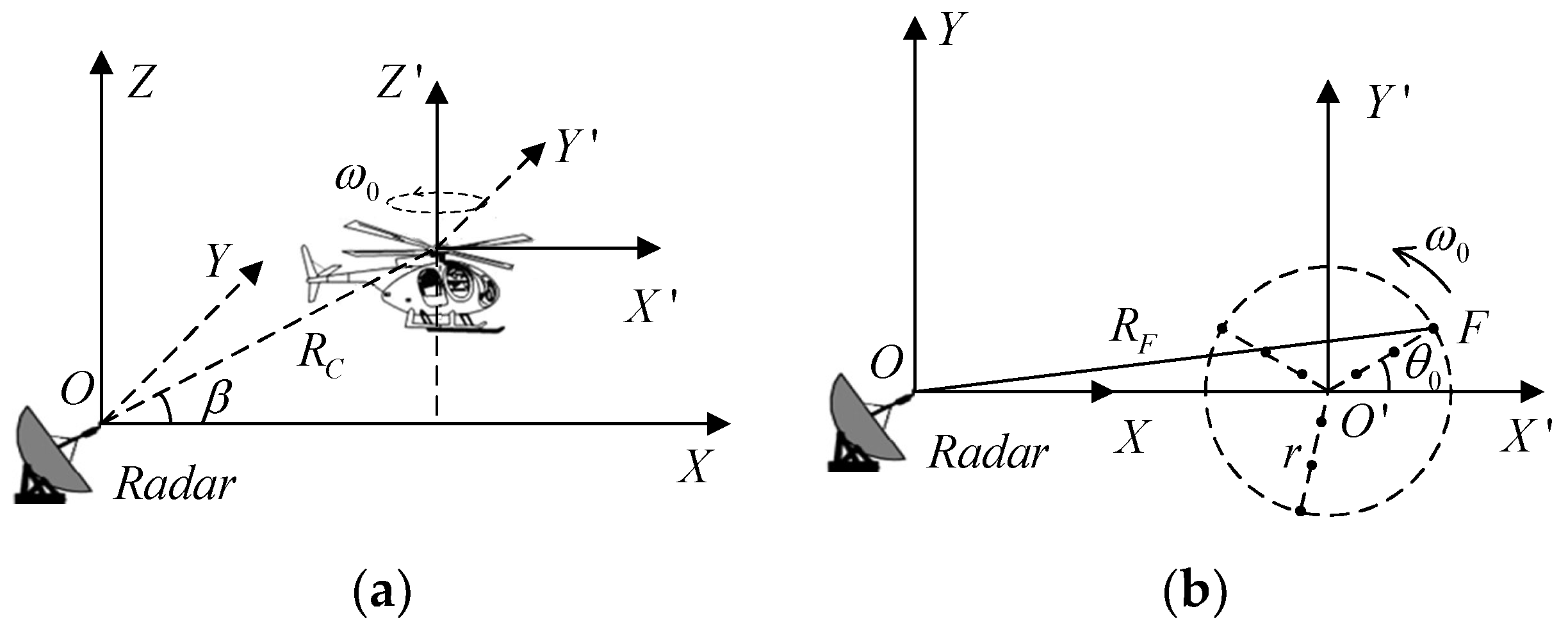
Figure 1. Geometry between radar and the rotor target: (a) space geometry; (b) two-dimensional plane geometry.
Remotesensing 14 04342 g001
Figure 2. Results of the frequency index residue initialization and iteration times: (a) frequency index residue initialization; (b) iteration times.
Remotesensing 14 04342 g002
Figure 3. Estimation results of the different algorithms when the rotational angular velocity is 30 rad/s: (a) success rate; (b) RMSE.
Remotesensing 14 04342 g003
Figure 4. Estimation results of different algorithms when the rotational angular velocity is 60 rad/s: (a) success rate; (b) RMSE.
Remotesensing 14 04342 g004
Figure 5. Estimation results of the different algorithms when the rotational angular velocity is 90 rad/s: (a) success rate; (b) RMSE.
Remotesensing 14 04342 g005
Figure 6. Estimation results of the different algorithms when the SNR is 30dB: (a) success rate; (b) RMSE.
Remotesensing 14 04342 g006
Figure 7. Estimation results of the different algorithms when the SNR is 60dB: (a) success rate; (b) RMSE.
Remotesensing 14 04342 g007
Table 1. Main parameters of the transmitted signal.
Transmitted Signal ParametersCarrier FrequencyBandwidthPulse Repetition FrequencyObservation TimePulse Samples
Value1 GHz2 MHz5 kHz50 ms250
Publisher’s Note: MDPI stays neutral with regard to jurisdictional claims in published maps and institutional affiliations.