Technical Note

High-Resolution Observation of Ionospheric E-Layer Irregularities Using Multi-Frequency Range Imaging Technology

1
Department of Space Physics, School of Electronic Information, Wuhan University, Wuhan 430072, China
2
China Research Institute of Radiowave Propagation (CRIRP), Qingdao 266107, China
3
Beijing Institute of Applied Meteorology, Beijing 100029, China
*
Author to whom correspondence should be addressed.
Remote Sens. 2023, 15(1), 285; https://doi.org/10.3390/rs15010285
Submission received: 2 December 2022 / Revised: 30 December 2022 / Accepted: 30 December 2022 / Published: 3 January 2023
(This article belongs to the Special Issue Ionosphere Monitoring with Remote Sensing II)

Abstract

:
E-region field-aligned irregularities (FAIs) are a hot topic in space research, since electromagnetic signal propagation through ionospheric irregularities can undergo sporadic enhancements and fading known as ionospheric scintillation, which could severely affect communication, navigation, and radar systems. However, the range resolution of very-high-frequency (VHF) radars, which is widely used to observe E-region FAIs, is limited due to its bandwidth. As a technology that is widely used in atmosphere radars to improve the range resolution of pulsed radars by transmitting multiple frequencies, this paper employed the multifrequency radar imaging (RIM) technique in a Wuhan VHF radar. The results showed that the range resolution of E-region FAIs greatly improved when compared with the results in traditional single-frequency mode, and that finer structures of E-region FAIs can be obtained. Specifically, the imaging results in multifrequency mode show that E-region FAIs demonstrate an overall descending trend at night, and it could be related to the tides or gravity waves due to their downward phase velocities or even driven by downwind shear. In addition, typical quasi-periodic (QP) echoes with a time period of around 10 min could be clearly seen using the RIM technique, and the features of the echoes suggest that they could be modulated by gravity waves. Furthermore, the RIM technique can be used to obtain the fine structure of irregularities within a short time period, and the hierarchical structure of E-region FAIs can be easily found. Therefore, the multifrequency imaging RIM technique is suitable for observing E-region FAIs and their evolution, as well as for identifying the different layers of E-region FAIs. Combined with the RIM technique, a VHF radar provides an effective and promising way to observe the structure of E-region FAIs in more detail to study the physical mechanism behind the formation and evolution of ionospheric E-region irregularities.

Graphical Abstract

1. Introduction

Ionospheric field-aligned irregularities (FAIs) are ionized “clumps” or “wave-like” structures of various scales floating in a normal ionospheric structure, and they are of critical importance for electromagnetic signal propagation [1,2,3]. Therefore, FAIs are one of the most important sources of disturbance for navigation, communication, and radar systems, and a remarkable set of comprehensive statistical studies have been conducted on ionospheric FAIs [4,5,6,7,8,9,10,11,12,13,14,15,16,17]. In addition, modeling and case studies have been carried out to reproduce ionospheric irregularities and to understand their mechanism [18,19,20,21,22,23,24,25,26,27,28]. Among them, midlatitude ionospheric E-region FAIs have been investigated for more than four decades since the first observation was made with a VHF radar over Arecibo [4,5,6,14,15,17,18,19,20,21,22,23,24,25,26,27,28,29,30,31].
In order to detect and characterize ionospheric irregularities, different instruments have been used, such as ionosondes, an airglow imager, coherent/incoherent scatter radars, and a global positioning satellite receiver [14,32,33]. Very-high-frequency (VHF) radars are one of the most widely used instruments due to their capability to detect small-scale irregularities, and these radars include the Japan middle and upper (MU) atmosphere radar, the standard frequency-agile radar (FAR), the Gadanki MST radar, Crete Island, the Chung-Li VHF radar, the Sanya VHF radar, and the Wuhan VHF radar. By using the radar observations, Yamamoto et al. [30] was the first to find that midlatitude E-region FAIs can be classified into two types: daytime continuous echoes at 90–100 km and nighttime quasi-periodic (QP) echoes at 100–130 km. Since then, considerable research has been devoted to the investigation of E-region FAIs, and several mechanisms have been proposed to explain the generation and evolution of FAIs. These mechanisms include atmosphere gravity waves (AGW), gradient-drift instability (GDI), Kelvin–Holmoholtz instability (KHI), and sporadic E (Es) layer instability [18,19,20,21,22,23,24]. Notably, the formation of midlatitude E-region FAIs is generally thought to be closely related to the Es layer since the seasonal variation in E-region FAI occurrence is consistent with the local Es occurrence [4,5]. Early and recent studies have shown that there is a positive correlation between the appearance of E-region FAIs and the difference in the critical frequency of a sporadic E layer (foEs) and the blanketing frequency of a sporadic E layer (fbEs) [14,34]. The simulation results also showed that the plasma density gradient in the Es layer represents a profile of the formation of E-region FAIs through gravity-wave modulation, Kelvin–Helmholtz instability generated by wind shear, and polarization electric fields associated with high-density plasma cloud embedded within sporadic E (Es) layers [18,19,21,23]. However, some questions such as the ionospheric E–F coupling phenomena and the effect of geomagnetic activity on E-region irregularity still remain to be thoroughly explained due to observational and modeling limitations.
Range resolution is one of the most important parameters in radar detection. As the most widely used instrument for E-region FAI measurements, the range resolution of a VHF radar is generally several hundred meters due to the bandwidth limitation; therefore, resolving the small-scale structure in a radar-illuminated volume is impossible [35]. To overcome this restriction, multifrequency radar imaging (RIM) technology, which has been used successively in atmospheric radars, was introduced into observations of E-region FAIs. Recently, Chen et al. [36,37,38] applied the RIM technique to the MU radar, and they found that the range resolution greatly improved such that finer structures could be obtained when compared with previous observations. However, no other specific studies have used RIM technology in VHF radars to observe irregularities. The Wuhan VHF radar is located at midlatitude for East Asia, a latitude lower than that of the MU radar. Previous studies have suggested that E-region FAIs have different features at different latitudes [3,15]. Therefore, in this paper, the RIM technique is employed to develop high-resolution imaging of ionospheric E-region FAIs based on the Wuhan VHF radar to expand upon the study of the fine structure of ionospheric irregularities at mid- and low latitudes. This paper is organized as follows: Section 2 presents the RIM technique based on Capon’s multifrequency interferometric imaging and the experimental setup of the VHF radar. Section 3 provides the results, which include the results of a standard range resolution after single-frequency acquisition and the results after the RIM technique processing. A discussion about the possible sources and mechanism behind the formation of E-region FAIs is given in Section 4. Section 5 presents a summary.

2. Method

2.1. Multifrequency Range Imaging Algorithm

In order to eliminate the limitations due to assumptions in the single Gaussian layer in the frequency-domain interference algorithm (FDI) and to further improve the resolution, Palmer et al. [39] developed a technique called range imaging, which uses the best combination of multiple frequency signals to reconstruct a fine-scale atmospheric structure within the resolution range. In this section, we use the Wuhan VHF radar to perform multifrequency range imaging to obtain fine-scale structures in the FAI echoing volume.
The RIM technique uses the Fourier method, the Capon method, the maximum entropy method, and other inversion algorithms to obtain an estimation of the so-called power density or brightness function of spatial refractive index fluctuations [40]. Among the inversion algorithms used with RIM, the Capon method [41] is robust [39,42]. Without considering Doppler-frequency sorting of the echoes, the Capon equations can be simply expressed as follows:
P ( r ) = 1 e H R 1 e
R = [ R 11 R 12 R 1 n R 21 R 22 R 2 n R n 1 R n 2 R n n ]
e = [ e j 2 k 1 r , e j 2 k 2 r , , e j 2 k n r ] T
where P ( r ) is the imaged power at the range r after range-scanning processing. The superscripts H and −1 in Equation (1) and T in Equation (3) represent, respectively, the Hermitian, inverse, and transposition operators; k n is the wave number of the nth carrier frequency; and R m n is the non-normalized cross-correlation function of the signals calculated at zero-time lag for a pair of frequencies. R m n can be simply written as
R m n = R m R n * = A m exp [ j ( 2 k m r m + φ m ) ] A n exp [ j ( 2 k n r n φ n ) ] = A m A n exp [ j 2 ( ( k n r n k m r m ) + ( φ m φ n ) ) ]
wherein   represents the overall average, r m   and   r n   represent the detection range of the scatterer, and φ m and φ n represent the phase terms related to the response of the system to different transmission frequencies.

2.2. Equipment and Experimental Setup

The Wuhan VHF radar, primarily operated at a central frequency of 48.2 MHz, can now generate carrier frequencies from 48.0 MHz to 48.4 MHz, with the smallest frequency step being 1 kHz. The carrier frequencies are generated with the same oscillator and can be changed from pulse to pulse to meet the basic requirement of RIM, that is, the echoes with various carrier frequencies are received almost simultaneously. The radar pulse shape can be Gaussian or rectangular, and complementary codes are usually employed to increase the signal-to-noise ratio (SNR). The VHF radar system used in the experiment is shown in Table 1.
Previous studies have found that the appearance of E-region irregularities in Wuhan is highest in summer [4,14,15]. Therefore, the experiment in this paper focuses on the period from June to August 2022 and uses RIM technology to carry out the radar frequency scanning test of the ionospheric E layer. In the current RIM test, 11 frequency points between 48.15 MHz and 48.25 MHz were used. The frequency interval was set as 10 KHz, and the bandwidth of the transmitted signal was 320 kHz. The selection and use of the above radar parameters were subject to the limitations in the capacity of the Wuhan VHF radar system. Table 2 lists some important radar parameters used in the test. The pulse-repetition frequency of these test-transmitted signals was 525 Hz, the sampling time was about 2 ms, and the number of coherent accumulations was 8. In total, 256 data points were used for each carrier frequency to estimate the non-normalized value in Equation (4), so the time resolution of the signal was about 1 min.
In this paper, a long-term experimental observation was carried out with this set of equipment. The specific detection method is shown in Figure 1. Several groups of pulse signals with similar carrier-frequency intervals were transmitted through the transmitter, corresponding to different beams kn and km, as shown in Figure 1. These pulse signals generated scattering echo after encountering ionospheric irregularities. Then, the echo signal was transmitted to the receiver through the 12 × 2 counter circle receiving an antenna array, and finally, the original data from the experimental analysis were obtained through digital signal processing of the receiver.
Taking the observation data within one minute as an example, the observation data in this experiment were processed as follows: first, we recorded 241 × 256 data corresponding to each frequency of each channel and processed 11 groups of data using Formula (2) for the baseband IQ data of a single channel. Thereafter, we obtained an 11 × 11 matrix R within each threshold value and calculated its inverse matrix R 1 . Then, the wave number k n was calculated according to the frequency, and each threshold scanning range gate ( Δ r = 500   m ) was subdivided into 50 layers, that is, the spacing r between adjacent layers after subdivision was 10 m. Finally, we used formula (3) to calculate the threshold scanning vector e and to conjugate transpose matrix e H , and substituted them into Formula (1) to obtain the scattering imaging power P ( r ) , which represents the “brightness density function” at each time period and detection range. As a result, the refined spatial distribution of the E-region FAIs can be seen from the figure.

3. Result

In order to determine the common height distribution of E-region irregularities, Figure 2 takes the normalized amplitude data of echo signals at different detection ranges within the period 14:01–14:03 UT on 10 July 2022 as an example. The figure clearly shows fewer data points, and that the amplitude distribution is sparse in most of the range gates, with amplitude values generally around 0. Specifically speaking, most of the normalized amplitude values are lower than 0.1, and the normalized amplitude around 155–165 km is larger than 0.2 at 14:01 UT. At 14:02 UT, most of the normalized amplitude is lower than 0.2, and the amplitude around 155–170 km is larger, with values more than 0.2. The normalized amplitude is lower than 0.2, and the amplitude around 160–175 km is larger than 0.2 at 14:03 UT. Therefore, the normalized amplitude values around 155–175 km vary widely and are significantly higher than those in the other detection ranges, which indicates the existence of irregularities in this distance range. The data at other time periods are similar to the above-demonstrated situation after extensive statistical analysis. Note that the relationship between the actual altitude H and the detection distance D is H = 2 / 2 × D, since the elevation angle of our antenna array is 45°. Therefore, the altitude of the common distribution of FAIs is between 95 and 123 km, consistent with that from previous studies [14,30]. In the following, we mainly focus on analyzing the morphology of irregularities within this altitude.
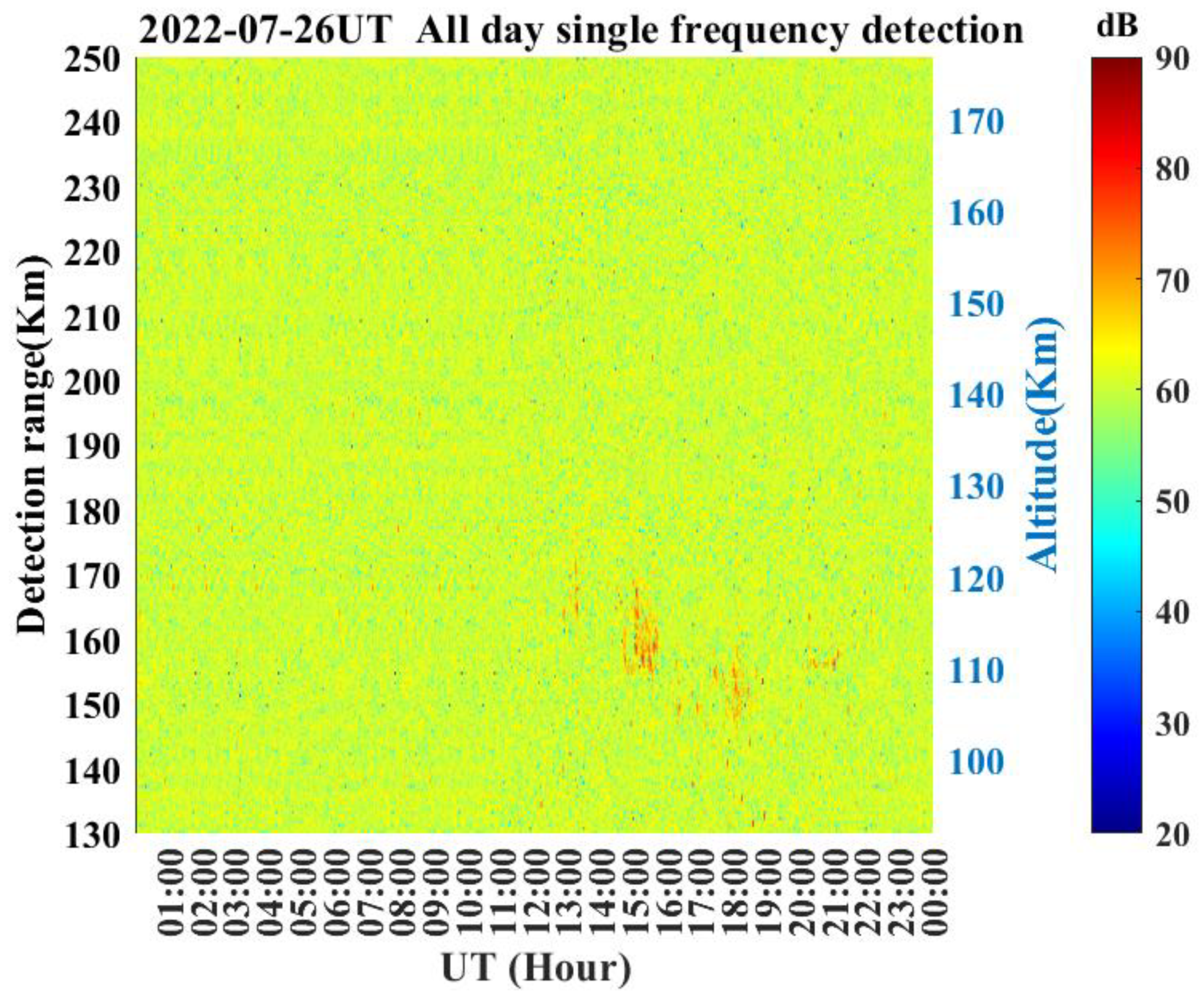
In order to verify the effectiveness and feasibility of the RIM algorithm, this paper uses single-frequency and multifrequency range imaging techniques to process the data on 26 July 2022. By using the data corresponding to a frequency of 48.2 MHz in the radar frequency scan test, the echo signal intensity is calculated to obtain the distribution of scattered power in the single-frequency mode, as shown in Figure 3. Note that the x axis represents UT hour, and the y axis represents detection ranges. In addition, the color represents intensity of the echo scattering power in Figure 3. The results show more obvious FAI echoes at the detection range of 155–175 km (corresponding to an altitude of 110–123 km) during 12:00–21:00 UT, which is in line with the common distribution of FAIs at the detection range given in Figure 2. However, due to the low range resolution, the echo pattern is more blurred in Figure 3. The FAI clumps show an obviously diffused state, and the spatial–temporal distribution features are difficult to accurately extract for the period 15:00–19:00 UT, especially for the time period of 17:00–19:00 UT.
Figure 4 displays the distribution of scattered power in multifrequency scanning mode during the same time period. It is of great importance that the x axis represents UT hour, and the y axis represents detection ranges. In addition, the color represents intensity of the echo scattering power in Figure 4. From the figure, the echo morphology is basically consistent with those in Figure 3; however, the echo morphology is more complete and the structure is clearer in multifrequency mode. Specifically, FAIs first appeared at 13:00 UT, with sporadic distribution in the detection range of 160–170 km. From 15:00 UT, a large range of irregularities appeared in the detection range of 150–170 km, lasting about one hour. At around 16:00 UT, the irregularities were found to be scattered at the detection range of 150 km. A large range of irregularities appeared again at the detection range of 140–160 km at 18:00 UT, and the overall altitude decreased by 7 km, on average, compared with the FAI two hours previously. Then, the FAI gradually disappeared within one hour. During the 20:30–21:30 UT period, the FAIs occurred again around the detection range of 155 km. Compared with the results of the single-frequency mode, the images processed by RIM technology are refined and complete in terms of both the morphological structure and echo distribution of the FAI, which is conducive to further research on its physical mechanism and evolution.
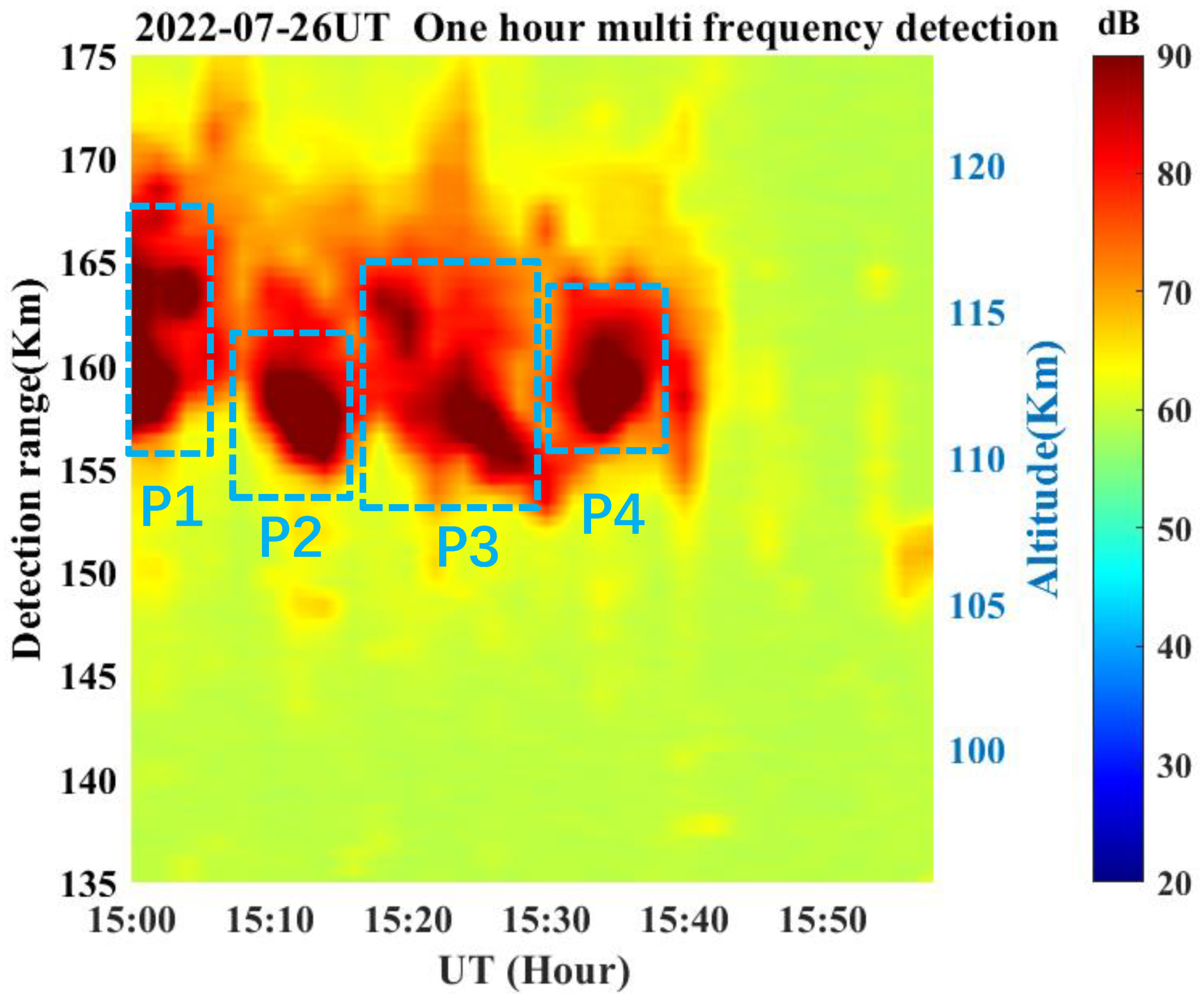
As the FAI for a whole day, shown in Figure 3 and Figure 4 above, is concentrated in some specific time periods and distance ranges, in order to further compare echoes under two modes. In this paper, data from the time range 15:00–16:00 UT and the detection range of 135–175 km were selected for analysis. The echo signal in this time period is strong and the echo quality is excellent, which is more conducive to observing the FAI structure after RIM processing and to conducting a comparative analysis with the single-frequency imaging results. The results are shown in Figure 5 and Figure 6. Note that the x axis represents UT hour, and the y axis represents detection ranges. In addition, the color represents intensity of the echo scattering power in Figure 5 and Figure 6.
Figure 5 shows that the echo distribution is accompanied by an obvious amplitude mutation on each range gate during 15:00–15:40 UT, due to the low initial range resolution in single-frequency mode. This directly leads to two problems: First, it is impossible to analyze the distribution of FAIs inside the original range gates. Second, the amplitude of FAI echoes between each range gate changed suddenly, which makes it impossible to accurately determine the position of the FAI and to observe its hierarchical structure.
Compared with the results of the single-frequency mode, Figure 6 shows that the echo in the multifrequency mode lasts longer and covers a wider area and that the echo signal is more continuous during the same time period. The FAI processed by RIM technology can not only obtain more precise echo-amplitude distribution inside each range gate, but also solve the amplitude mutation problem between each range gate. Specifically, the FAI structures in the P1–P4 period circled in Figure 6 can also accurately determine the evolution of FAIs. Specifically, the overall altitude of the FAI decreased by 4 km in the period of P1 to P2, and the FAI in P2 remained stable for about 10 min within the detection range of 155–160 km. The FAI in the P3 period obviously drifted downward, from the initial range of 165 km (altitude of 116 km) to 155 km (altitude of 110 km). Finally, it is stably distributed within the range of 157–163 km in the P4 period, lasting for 5 min.
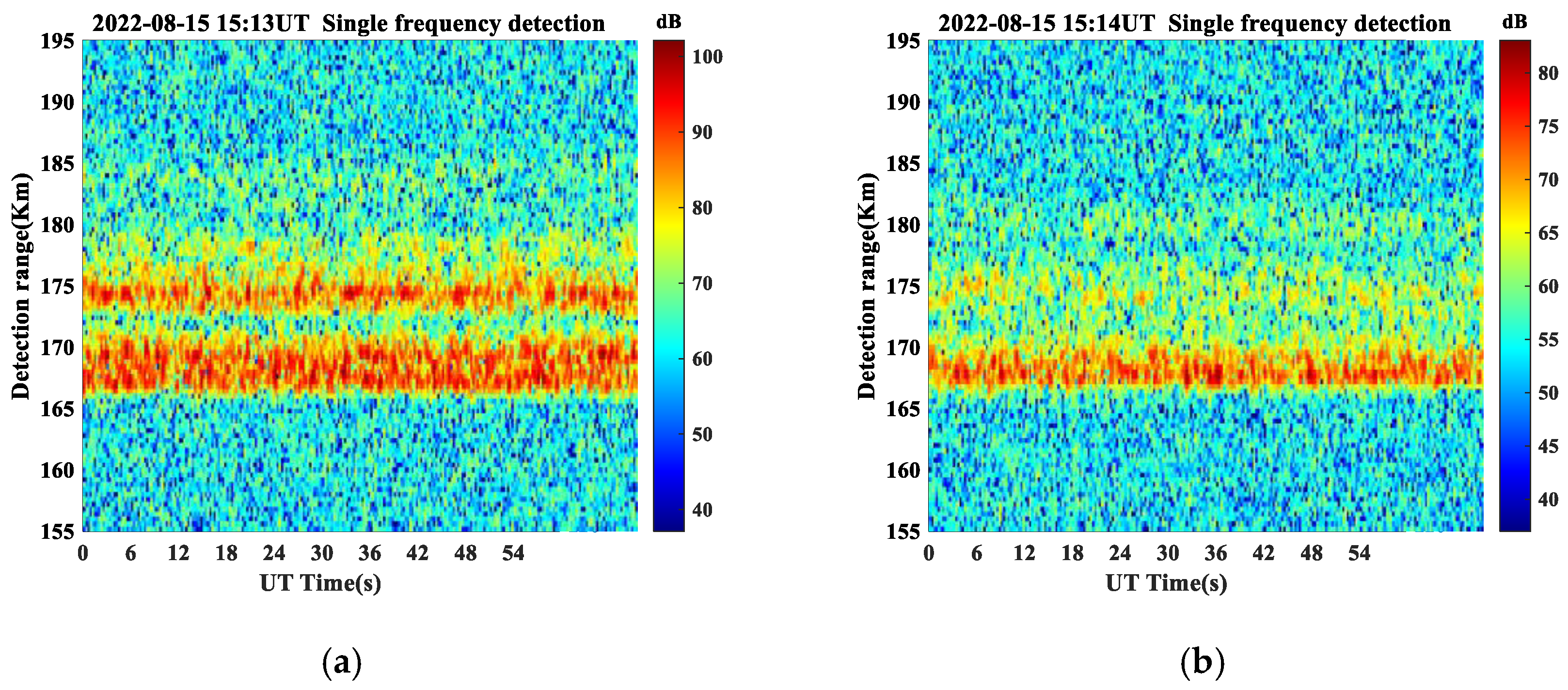
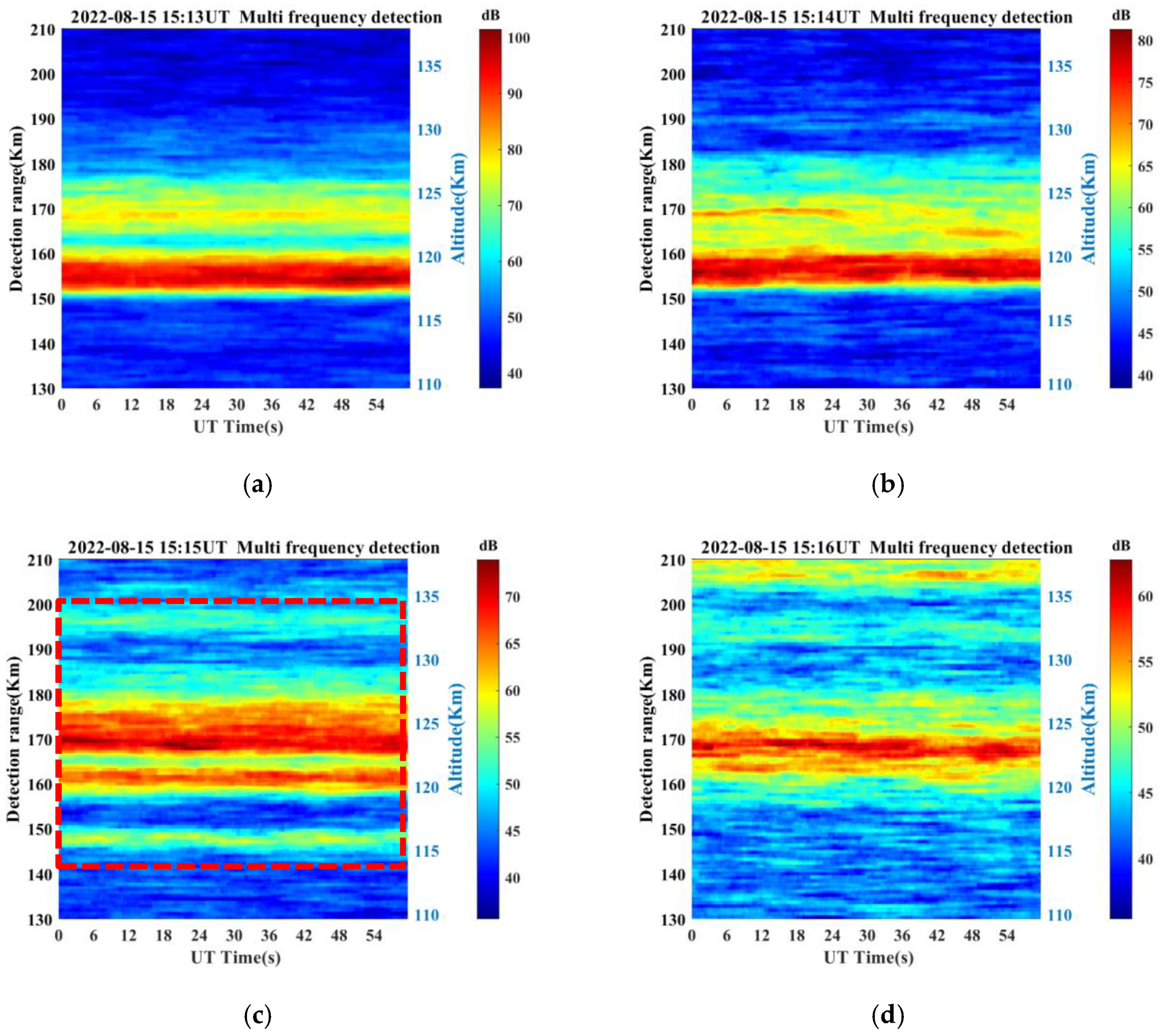
Further research shows that the multifrequency range imaging technique can also be used to obtain the fine structure of irregularities within a short time period. Taking the results of 15:01–15:04 UT on 15 August 2022 as an example, Figure 7 and Figure 8 show the comparison between the imaging of single-frequency mode and those processed by RIM technology. It is important to note that the x axis represents UT hour, and the y axis represents detection ranges. In addition, the color represents intensity of the echo scattering power in Figure 7 and Figure 8. Figure 7 shows that the imaging results are relatively fuzzy due to the low range resolution in the single-frequency mode. In terms of temporal and spatial distribution, the continuity of the scattering echo power density function is poor in time and range, resulting in the imaging results being unable to reflect the specific altitude and duration of the FAI. By contrast, from Figure 8, the image results are more refined after RIM processing, and the hierarchical structure of FAIs is clearer. For example, the FAI layering structure is obvious at 15:03 UT, and they can be divided into four layers, located at the detection ranges of 187 km, 173–180 km, 169–171 km, and 164 km (corresponding to altitudes of 132 km, 122 km–127 km, 119 km–121 km, and 116 km, respectively). Therefore, the height information and inter-layer spacing of each layer structure can be effectively extracted. Specifically, FAIs were concentrated in the range of 165–170 km in the first two minutes, and a small amount of FAIs were found in the range of 175 km according to the temporal–spatial distribution of FAIs in these four minutes. At 15:03 UT, the FAIs were mainly distributed in the range of 173–177 km, with obvious multilayer structures. Moreover, FAIs were concentrated within the range of 170–180 km at 15:04 UT. In summary, the FAI was relatively stable in terms of spatial–temporal distribution within a short time period but was also accompanied by changes in altitude and stratification. Therefore, the temporal distribution of irregularities within a short time period can be observed through the results of RIM technology processing, which would provide observational support for research on the physical properties and evolution process of FAIs within a short time period.

4. Discussion

RIM is a technology that is widely used in atmosphere radars to improve the range resolution of pulsed radars by transmitting multiple frequencies. Chen et al. [36,37,38] have verified its feasibility and effectiveness in the detection of E-region FAIs using the MU radar. To expand this technique into the observation of E-region FAIs using other VHF radars, in this paper, the RIM technique was employed using the Wuhan VHF radar. The results show that the range resolution of E-region FAIs significantly improved when compared with original single-frequency imaging. It is of great importance to note that the improvement of range resolution depends on two aspects. On the one hand, it depends on the wavelength of the carrier frequency. The central frequency of our experiment is 48.2 MHz, and the corresponding wavelength is about 6.2 m. Therefore, our imaging limit of range resolution cannot exceed 3.1 m. On the other hand, it depends on the characteristics of the detection target. For irregularities, its horizontal and vertical distribution has a large spatial scale, and the distance between layers is also large. We have carried out many experiments, and the results show that the range resolution of 10 m produces the ideal result to further improve the range resolution of imaging and the computational complexity of the algorithm; however, it cannot improve the imaging result. Therefore, this paper uses 10 m as the final range resolution for multifrequency modes. In addition, the results show the details of some typical features of FAI, such as QP echoes and hierarchical structures; they can, therefore, be used in an investigation of the formation and evolution processes of the E-region FAIs discussed below.
Processed with multifrequency RIM technology, Figure 4 clearly shows that the E-region FAIs demonstrate an overall descending trend when compared with Figure 3, and their height distributions decreased from 160–170 km at 13:00 UT to 140–160 km at 18:00 UT. Previous studies have also found a downward trend to be one of E-region FAIs’ characteristics and proposed that it may be caused by tides or gravity waves with downward phase velocities or even driven by downwind shear [43,44]. The Es layer, which is closely related to the E-region FAI, also shows a downward trend, which was confirmed in previous studies [45,46]. Therefore, the descending E-region FAIs might be related to the downward trend of the Es layer. However, the physical mechanisms behind the downward trend of E-region FAIs still needs to be explored with more observations and modeling.
In Figure 6, the echoes of E-region FAIs show a quasi-period feature, which belongs to the QP echoes (type 2 echoes). From the figure, the period of the echoes is almost 10 min during the P1-P4 period, which is a typical period of a gravity wave. In addition, the echo power displays a periodic variation in a wave-like pattern. Therefore, we preliminarily conclude that the generation of QP echoes is modulated by a gravity waves. Woodman [18] first suggested that the existing Es layers might be modulated by passing atmospheric gravity waves (AGW), and Tsunoda et al. [19] further proposed that the polarization process will be excited in the presence of background ionospheric winds and wind-driven dynamo electric fields during AGW modulation. Moreover, neutral dynamic instability (gradient-drift instability and Kelvin–Helmholtz instability) and plasma instability (Es-layer instability) were suggested to be responsible for the formation of QP echoes [21,22,23,24,25,26]. Although it remains unclear which mechanism is the dominant mechanism, the high-resolution observation being processed with the RIM technique provides a convenient and promising way to investigate this question.
In addition to the results of a period, the RIM technique can also be applied to observe irregularities within a short time period, as Figure 8 clearly shows the hierarchical structure of E-region FAIs. Early and recent studies have found that the hierarchical structure of E-region FAIs could also be seen at other observation sites, suggesting that it is one of the frequent phenomena of E-region FAIs. Using an Arecibo incoherent scatter radar (ISR) observation, Early et al. [45] found that the maximum of an electron density gradient can appear at different heights (two to three, or more) in the E-region, that is, a multiple Es-layer structure. Szuszczewicz et al. [47] also found the appearance of a multiple Es layer from a Townsville ionosonde observation, and this structure could be found at other ionosonde observations [6,43]. Therefore, the hierarchical structure of E-region FAIs could be closely related to the multiple E-layer structure. The mechanisms behind the formation of E-region FAIs described above could be used to explain the hierarchical structure of E-region FAIs. The multilayered FAI structure at night may be caused by the gradient-drift instability acting on multiple ionized density-gradient layers formed by tides or gravity waves. Specifically, the multiple Es layer indicates the development of an electron density gradient and strong spatial structuring in the electron density, and the ambient electric field in the Es layers could excite the stronger FAIs around the local Es altitude [48]. This example demonstrates that the spatial resolution of the E-region FAIs is improved by the RIM technique and is suitable for the observation of multiple layers of E-region FAIs.

5. Conclusions

In this study, we applied the multifrequency range imaging RIM technique to improve the range resolution of a VHF radar for observing E-region FAIs. The results are generally consistent with those of previous studies for E-region FAIs; however, the spatial resolution of E-region FAIs greatly improved when compared with the single-frequency imaging technique, and finer structures such as QP echoes can be obtained through the RIM technique. The quasi-period features of the echoes indicate that the generation of QP echoes are modulated by gravity waves. Moreover, the RIM technique was found to also be applicable to the observation of irregularities within a short time period, and is particularly suitable for the observation of multiple layers of E-region FAIs. The multilayered FAI structure at night might be caused by a gradient-drift instability acting on multiple ionized density-gradient layers formed by tides or gravity waves. By using the RIM technique, the VHF radar provides convenient and promising ways for more refined observations of E-region FAIs, as well as the physical mechanisms involved in the generation and evolution of the FAIs. More observations and simulations will be combined with these high-resolution imaging results in our future work to study E-region FAIs.

Author Contributions

Conceptualization, Y.Z. (Yuqiang Zhang), J.F. and Y.L.; methodology, Z.Z.; investigation, C.Z. and Y.Z. (Yufeng Zhou); validation, J.F. and B.C.; formal analysis, B.C. and Y.L.; resources, Y.Z. (Yuqiang Zhang) and Z.Z.; visualization, J.F. and Y.Z. (Yufeng Zhou); funding acquisition, Y.L. and B.C. All authors have read and agreed to the published version of the manuscript.

Funding

This work was supported by the Stable-Support Scientific Project of the China Research Institute of Radio Wave Propagation (grant No. A132102W06), the Hubei Natural Science Foundation (grant No. 2022CFB651), the National Natural Science Foundation of China (NSFC grant No. 42204161, 42074187), the Foundation of National Key Laboratory of Electromagnetic Environment (grant No. 20200101), and the Excellent Youth Foundation of Hubei Provincial Natural Science Foundation (grant No. 2019CFA054).

Data Availability Statement

Not applicable.

Acknowledgments

The authors gratefully thank the anonymous reviewers for their insight and help. The observation data on the VHF radar are available by contacting Yuqiang Zhang ([email protected]).

Conflicts of Interest

The authors declare no conflict of interest.

References

  1. Booker, H.G. Turbulence in the ionosphere with applications to meteor trails. radio-star scintillation, auroral radar echoes, and other phenomena. J. Gephys. Res. 1956, 61, 673–705. [Google Scholar] [CrossRef]
  2. Ratcliffe, J.A. An Introduction to the Ionosphere and Magnetosphere; Cambridge University Press: Cambridge, UK, 1972. [Google Scholar]
  3. Balan, N.; Liu, L.; Le, H. A brief review of equatorial ionization anomaly and ionospheric irregularities. Earth Planet. Phys. 2018, 2, 257–275. [Google Scholar] [CrossRef]
  4. Yamamoto, M.; Fukao, S.; Ogawa, T.; Tsuda, K.; Kato, S. A morphological study on mid-latitude E-region field-aligned irregularities observed with the MU radar. J. Atmos. Sol. Terr. Phys. 1992, 54, 769–777. [Google Scholar] [CrossRef]
  5. Haldoupis, C.; Schlegel, K. Characteristic of midlatitude coherent backscatter from the ionospheric E region obtained with Sporadic E scatter experiment. J. Geophys. Res. 1996, 101, 13387–13397. [Google Scholar] [CrossRef]
  6. Fukao, S.; Yamamoto, M.; Tsunoda, R.T.; Hayakawa, H.; Mukai, T. The SEEK (Sporadic-E Experiment over Kyushu) Campaign. Geophys. Res. Lett. 1998, 25, 1761–1764. [Google Scholar] [CrossRef]
  7. Woodman, R.F.; Chau, J.L.; Aquino, F.; Rodriguez, R.R.; Flores, L.A. Low-latitude field-aligned irregularities observed in the E region with the Piura VHF radar, First results. Radio Sci. 1999, 34, 983–990. [Google Scholar] [CrossRef]
  8. Chau, J.L.; Woodman, R.F.; Flores, L.A. Statistical characteristics of low-latitude ionospheric field-aligned irregularities obtained with the Piura VHF radar. Ann. Geophys. 2002, 20, 1203–1212. [Google Scholar] [CrossRef] [Green Version]
  9. Patra, A.K.; Sripathi, S.; Sivakumar, V.; Rao, P.B. Statistical characteristics of VHF radar observations of low latitude E-region field-aligned irregularities over Gadanki. J. Atmos. Sol.-Terr. Phys. 2004, 66, 1615–1626. [Google Scholar] [CrossRef]
  10. Ning, B.; Hu, L.; Li, G.; Liu, L.; Wan, W. The first time observations of low-latitude ionospheric irregularities by VHF radar in Hainan. Sci. China Technol. Sci. 2012, 55, 1189–1197. [Google Scholar] [CrossRef]
  11. Li, G.Z.; Ning, B.Q.; Hu, L.; Li, M. Observations on the field-aligned irregularities using Sanya VHF radar, 2. Low latitude Ionospheric E-region quasi-periodic echoes in the East Asian sector. Chin. J. Geophys. 2013, 56, 2141–2151. (In Chinese) [Google Scholar]
  12. Li, G.Z.; Ning, B.Q.; Hu, L. Interferometry observations of low latitude E-region irregularity patches using the Sanya VHF radar. Sci. China Technol. Sci. 2014, 57, 1552–1561. [Google Scholar] [CrossRef]
  13. Wang, C.; Chu, Y.-H.; Su, C.; Kuong, R.; Chen, H.-C.; Yang, K. Statistical investigations of layer-type and clump-type plasma structures of 3-m field-aligned irregularities in nighttime sporadic E region made with Chung-Li VHF radar. J. Geophys. Res. 2011, 116, A12311. [Google Scholar] [CrossRef] [Green Version]
  14. Zhou, C.; Liu, Y.; Tang, Q.; Gu, X.; Nin, B.; Zhao, Z. Investigation on the occurrence of mid-latitude E-region irregularity by Wuhan VHF radar and its relationship with sporadic E layer. IEEE Trans. Geosci. Remote Sens. 2018, 99, 7207–7216. [Google Scholar] [CrossRef]
  15. Tsunoda, R.T.; Buoncore, J.J.; Saito, A.; Kishimoto, T.; Fukao, S.; Yamamoto, M. First observations of quasi-periodic radar echoes from Stanford, California. Geophys. Res. Lett. 1999, 26, 995–998. [Google Scholar] [CrossRef]
  16. Aa, E.; Zou, S.; Liu, S. Statistical Analysis of Equatorial Plasma Irregularities Retrieved From Swarm 2013–2019 Observations. J.Geophys. Res. 2020, 125, e27022. [Google Scholar] [CrossRef]
  17. Liu, Y.; Zhou, C.; Xu, T.; Deng, Z.; Du, Z.; Lan, T.; Tang, Q.; Zhu, Y.; Wang, Z.; Zhao, Z. Geomagnetic and solar dependencies of midlatitude E-region irregularity occurrence rate, A climatology based on Wuhan VHF radar observations. J. Geophys. Res. Space Phys. 2022, 127, e2021JA029597. [Google Scholar] [CrossRef]
  18. Woodman, R.F.; Yamamoto, M.; Fukao, S. Gravity wave modulation of gradient drift instabilities in mid-latitude sporadic E irregularities. J. Geophys. Res. 1991, 18, 1197–1200. [Google Scholar]
  19. Tsunoda, R.T.; Fukao, S.; Yamamoto, M. On the origin of quasiperiodic radar backscatter from midlatitude sporadic E. Radio Sci. 1994, 29, 349–365. [Google Scholar] [CrossRef]
  20. Yokoyama, T.; Horinouchi, T.; Yamamoto, M.; Fukao, S. Modulation of the midlatitude ionospheric E region by atmospheric gravity waves through polarization electric field. J. Geophys. Res. 2004, 109, A12307. [Google Scholar] [CrossRef]
  21. Larsen, M.F. A shear instability seeding mechanism for quasiperiodic radar echoes. J. Geophys. Res. 2000, 105, 24931–24940. [Google Scholar] [CrossRef]
  22. Maruyama, T.; Fukao, S.; Yamamoto, M. A possible mechanism for echo striation generation of radar backscatter from midlatitude sporadic E. Radio Sci. 2000, 35, 1155–1164. [Google Scholar] [CrossRef]
  23. Bernhardt, P.A. The modulation of sporadic-E layers by Kelvin–Helmholtz billows in the neutral atmosphere. J. Atmos. Sol.-Terr. Phys. 2002, 64, 1487–1504. [Google Scholar] [CrossRef]
  24. Cosgrove, R.B.; Tsunoda, R.T. Simulation of the nonlinear evolution of the sporadic-E layer instability in the nighttime midlatitude ionosphere. J. Geophys. Res. 2003, 108, 1283. [Google Scholar] [CrossRef]
  25. Cosgrove, R.B.; Tsunoda, R.T. Instability of the E-F coupled nighttime midlatitude ionosphere. J. Geophys. Res. 2004, 109, A04305. [Google Scholar]
  26. Cosgrove, R.B.; Tsunoda, R.T.; Fukao, S.; Yamamoto, M. Coupling of the Perkins instability and the sporadic E layer instability derived rom physical arguments. J. Geophys. Res. 2004, 109, A06301. [Google Scholar]
  27. Liu, Y.; Zhou, C.; Tang, Q.; Kong, J.; Gu, X.D.; Ni, B.B.; Yao, Y.B.; Zhao, Z.Y. Evidence of mid- and low-latitude nighttime ionospheric E-F coupling, coordinated observations of sporadic E layers, F-region field aligned irregularities, and medium-scale traveling ionospheric disturbances. IEEE Trans. Geosci. Remote Sens. 2019, 57, 7547–7557. [Google Scholar] [CrossRef]
  28. Wu, J.; Zhou, C.; Wang, G.; Liu, Y.; Jiang, C.; Zhao, Z. Simulation of Es Layer Modulated by Nonlinear Kelvin Helmholtz Instability. J. Geophys. Res. Space Phys. 2021, 127, e2021JA030065. [Google Scholar] [CrossRef]
  29. Ecklund, W.L.; Carter, D.A.; Balsley, B. Gradient drift irregularities in mid-latitude sporadic E. J. Geophys. Res. 1981, 86, 858–862. [Google Scholar] [CrossRef]
  30. Yamamoto, M.; Fukao, S.; Woodman, R.F.; Ogawa, T.; Tsuda, T.; Kato, S. Midlatitude E region field-aligned irregularities observed with the MU radar. J. Geophys. Res. 1991, 96, 15943–15949. [Google Scholar] [CrossRef]
  31. Haldoupis, C.; Schlegel, K.; Farley, D.T. An explanation for type 1 radar echoes from the midlatitude E-region ionosphere. Geophys. Res. Lett. 1996, 23, 97–100. [Google Scholar] [CrossRef]
  32. Jin, H.; Zou, S.; Chen, G.; Yan, C.; Zhang, S.; Yang, G. Formation and Evolution of Low-Latitude F Region Field-Aligned Irregularities During the 7–8 September 2017 Storm, Hainan Coherent Scatter Phased Array Radar and Digisonde Observations. Space Weather 2018, 16, 648–659. [Google Scholar] [CrossRef]
  33. Jin, S.; Wang, Q.; Dardanelli, G. A Review on Multi-GNSS for Earth Observation and Emerging Applications. Remote Sens. 2022, 14, 3930. [Google Scholar] [CrossRef]
  34. Maruyama, T.; Saito, S.; Yamamoto, M.; Fukao, S. Simultaneous observation of sporadic E with a rapid-run ionosonde and VHF coherent backscatter radar. Ann. Geophys. 2006, 24, 153–162. [Google Scholar] [CrossRef]
  35. Chen, J.-S.; Zecha, M. Multiple-frequency range imaging using the OSWIN VHF radar, Phase calibration and first results. Radio Sci. 2009, 44, RS1010. [Google Scholar] [CrossRef]
  36. Chen, J.-S.; Chu, Y.-H.; Su, C.-L.; Hashiguchi, H.; Li, Y. Range imaging of E-region field-aligned irregularities by using a multifrequency technique, Validation and initial results. IEEE Trans. Geosci. Remote Sens. 2016, 54, 3739–3749. [Google Scholar] [CrossRef]
  37. Chen, J.-S.; Wang, C.-Y.; Chu, Y.-H.; Su, C.-L.; Hashiguchi, H. 3-D Radar Imaging of E-Region Field-Aligned Plasma Irregularities by Using Multireceiver and Multifrequency Techniques. IEEE Trans. Geosci. Remote Sens. 2018, 56, 5591–5599. [Google Scholar] [CrossRef]
  38. Chen, J.-S.; Wang, C.-Y.; Chu, Y.-H. Measurement of Aspect Angle of Field-Aligned Plasma Irregularities in Mid-Latitude E Region Using VHF Atmospheric Radar Imaging and Interferometry Techniques. Remote Sens. 2022, 14, 611. [Google Scholar] [CrossRef]
  39. Palmer, R.D.; Yu, T.Y.; Chilson, P.B. Range imaging using frequency diversity. Radio Sci. 1999, 34, 1485–1496. [Google Scholar] [CrossRef]
  40. Yu, T.Y.; Palmer, R.D. Atmospheric radar imaging using multiple-receiver and multiple-frequency techniques. Radio Sci. 2001, 36, 1493–1503. [Google Scholar] [CrossRef]
  41. Capon, J. High-resolution frequency-wavenumber spectrum analysis. Proc. IEEE 1969, 57, 1408–1418. [Google Scholar] [CrossRef] [Green Version]
  42. Luce, H.; Hassenpflug, G.; Yamamoto, M.; Fukao, S. High-resolution vertical imaging of the troposphere and lower stratosphere using the new MU radar system. Ann. Geophys. 2006, 24, 791–804. [Google Scholar] [CrossRef] [Green Version]
  43. Ning, B.; Li, Z.; Hu, L.L.M. Observations on the field-aligned irregularities using Sanya VHF radar, 1. Ionospheric E-region continuous echoes. Chin. J. Geophys. 2013, 56, 719–730. (In Chinese) [Google Scholar]
  44. Zhang, S.; Zhao, Z.; Zhou, C.; Ni, B.G.X. Wuhan VHF coherent scattering radar and its initial observation results. Mod. Electron. Tech. 2016, 39, 1–5. [Google Scholar]
  45. Earle, G.D.; Bishop, R.L.; Collins, S.C.; Gonzalez, S.A.; Sulzer, M.P. Descending layer variability over Arecibo. J. Geophys. Res. 2000, 105, 24951–24961. [Google Scholar] [CrossRef]
  46. Mathews, J.D. Sporadic E, Current views and recent progress. J. Atmos. Sol. Terr. Phys. 1998, 60, 413–435. [Google Scholar] [CrossRef]
  47. Szuszczewicz, E.P.; Roble, R.G.; Wilkinson, P.J.; Hanbaba, R. Coupling mechanisms in the lower ionospheric-thermospheric system and manifestations in the formation and dynamics of intermediate and descending layers. J. Atmos. Terr. Phys. 1995, 57, 1483–1496. [Google Scholar] [CrossRef]
  48. Zhu, Y.; Tang, Q.; Deng, Z.; Zhou, C.; Liu, Y.; Xu, T.; Wang, Z.; Zhao, Z.; Wei, F.; Feng, X. The study of daytime ionospheric E-region radar echoes simultaneously observed by Qujing VHF radar and multi-ionosondes. Space Weather 2022, 20, e2021SW002998. [Google Scholar] [CrossRef]
Figure 1. VHF radar configuration of multifrequency range imaging technology for irregular body detection.
Remotesensing 15 00285 g001
Figure 2. Normalized amplitude distribution of VHF radar original detection data of the E layer measured in Wuhan within the period 14:01–14:03 UT on 10 July 2022 (from top to bottom is 14:01–14:03 UT).
Remotesensing 15 00285 g002
Figure 3. Echo scattering power under single-frequency mode of E layer measured in Wuhan on 26 July 2022. Note that the x axis represents UT hour, and the y axis represents detection range. In addition, the color represents intensity of the echo scattering power.
Remotesensing 15 00285 g003
Figure 4. Same as Figure 3 but for the echo scattering power in multifrequency scanning mode.
Remotesensing 15 00285 g004
Figure 5. Echo scattering power under single-frequency mode of E layer measured in Wuhan at 15:00–16:00 UT on 26 July 2022. Note that the x axis represents UT hour, and the y axis represents detection range. In addition, the color represents intensity of the echo scattering power.
Remotesensing 15 00285 g005
Figure 6. Same as Figure 5 but for the echo scattering power in multifrequency scanning mode.
Remotesensing 15 00285 g006
Figure 7. Echo scattering power under single frequency mode of E layer measured at 15:12–15:16 UT on 15 August 2022 in Wuhan. (a) Echo scattering power measured at 15:12–15:13 UT. (b) Echo scattering power measured at 15:13–15:14 UT. (c) Echo scattering power measured at 15:14–15:15 UT on 15 August 2022. (d) Echo scattering power measured at 15:15–15:16 UT. Note that the x-axis represents UT hours and the y-axis represents the detection range. In addition, the color indicates the intensity of the echo scattering power.
Remotesensing 15 00285 g007aRemotesensing 15 00285 g007b
Figure 8. Same as Figure 7 but for the echo scattering power under the multifrequency scanning mode of E layer measured at 15:12–15:16 UT on 15 August 2022 in Wuhan. (a) Echo scattering power measured at 15:12–15:13 UT. (b) Echo scattering power measured at 15:13–15:14UT. (c) Echo scattering power measured at 15:14–15:15 UT. (d) Echo scattering power measured at 15:15–15:16 UT.
Remotesensing 15 00285 g008
Table 1. VHF radar system introduction.
SystemVHF Pulse Doppler Radar
Center frequency48.2 MHz
Antenna1 sending and 24 receiving
TransmitterPeak power: 20 Kw
Receiver6 Digital channel receiving system
Peripherals24 antennas for layer E FAI observation
Table 2. Wuhan VHF radar parameters in the experiment.
ParameterNumerical Value
Observation site(114.2°E, 30.3°N)
Observation timeFrom 15 July 2022 to now
Distance range130 km–250 km
Original range resolution500 m
Time resolution1 min
Pulse repetition rate550 Hz
Coherent accumulation times8
Coding system16 bit complementary code
Transmission signal bandwidth320 kHz
Carrier frequency (MHz)48.15, 48.16, 48.17, 48.18, 48.19
48.20, 48.21, 48.22, 48.23, 48.24, 48.25
Disclaimer/Publisher’s Note: The statements, opinions and data contained in all publications are solely those of the individual author(s) and contributor(s) and not of MDPI and/or the editor(s). MDPI and/or the editor(s) disclaim responsibility for any injury to people or property resulting from any ideas, methods, instructions or products referred to in the content.