Article

MIMO DFRC Signal Design in Signal-Dependent Clutter

1
School of Information Science and Engineering, Southeast University, Nanjing 210096, China
2
School of Information and Communication Engineering, University of Electronic Science and Technology of China, Chengdu 611731, China
3
School of Electronic and Information Engineering, Chongqing Three Gorges University, Chongqing 404020, China
*
Author to whom correspondence should be addressed.
Remote Sens. 2023, 15(13), 3256; https://doi.org/10.3390/rs15133256
Submission received: 22 May 2023 / Revised: 19 June 2023 / Accepted: 22 June 2023 / Published: 24 June 2023
(This article belongs to the Special Issue Theory and Applications of MIMO Radar)

Abstract

:
This paper deals with the Dual-Function Radar and Communication (DFRC) signal design for a Multiple-Input–Multiple-Output (MIMO) system, considering the presence of signal-dependent clutter. A modulation methodology called Spectral Position Index and Amplitude (SPIA) modulation is proposed, which involves selecting passband and stopband positions and applying amplitude modulation. Signal to Interference plus Noise Ratio (SINR) is maximized to enhance radar detectability. Meanwhile, variable modulus and communication modulation constraints are enforced to ensure compatibility with the current hardware techniques and communication demand, respectively. In addition, the mainlobe width and sidelobe level constraints used to concentrate energy in a specific area of space are enforced. To tackle the resulting nonconvex and NP-hard optimization problem, an Iterative Block Enhancement (IBE) framework that alternately updates each signal in each emitting antenna is exploited to monotonically increase SINR. Each block involves the Dinkelbach’s Iterative Procedure (DIP), Sequential Convex Approximation (SCA) and Alternating Direction Method of Multipliers (ADMM) to obtain a single signal. The computational complexity and convergence of the algorithm are analyzed. Finally, the numerical results highlight the effectiveness of the proposed dual-function scheme in sidelobe signal-dependent clutter.

1. Introduction

The Dual-Function Radar and Communication (DFRC) system has attracted significant attention due to its advantages of a small size, low cost, and strong mobility. This system can be classified into two categories: communication-centric and radar-centric. The radar-centric DFRC system primarily focuses on detection and emits a dual-function signal for both detection and communication using the radar system’s available resources. However, designing a dual-function signal poses a considerable challenge. Existing works primarily concentrate on utilizing Degrees of Freedom (DoFs) of different dimensions to achieve this dual function.
Earlier studies explored the combination of a Linear Frequency Modulation (LFM) signal and Phase Shift Keying (PSK) modulation [1,2]. However, LFM-PSK signals often exhibit higher autocorrelation sidelobe levels compared to standard LFM. Another approach involves embedding information in the transform domain of the dual-function signal. Various modulation methods have been proposed, such as frequency nulling modulation [3], Ambiguity Function (AF) sidelobe nulling modulation [4], and watermarking demodulation [5]. The data rates of the mentioned methods [1,2,3,4,5] are limited as they only consider modulation in the time and frequency domains.
The Multiple-Input–Multiple-Output (MIMO) system has garnered attention due to its potential for spatial domain modulation. In [6,7,8], researchers have embedded information in an orthogonal frequency-hopping signal cluster, capitalizing on the increased possibilities offered by MIMO systems. Alternatively, [9,10,11] form different sidelobe levels or/and different phases for the communication users by designing the weight vector and exploiting signal diversity. In [12], a spatio-spectral method is proposed by shaping the energy spectral density of synthetic signals in users’ directions. Ref. [13] maximizes the Signal to Interference plus Noise Ratio (SINR) under power and communication modulation constraints. To improve the data rate, related studies [14,15,16,17,18,19] have introduced the concept of index modulation in dual-function signal design by drawing inspiration from index modulation techniques employed in the communication literature [20,21,22]. It is important to note that the distinction between these studies lies in the specific application scenario. The former focuses on DFRC systems, while the latter primarily pertains to communication systems. For instance, the communication scheme of the DFRC system in [17] exploits the agile profile of the radar signals to convey its message via frequency and spatial index modulation.
However, the radar-centric DFRC system always operates in a complex electromagnetic countermeasure environment. The existing non-uniform, changeable and strong independent clutter degrades the radar detection performance. Many works have been employed in MIMO radar signal design with uniform or non-uniform clutter [23,24,25,26,27,28,29,30,31]. Recently, a radar-centric dual-function signal design in a signal-dependent clutter environment ias pursued to maximize the SINR [32,33,34]. In [32], a constant-envelope DFRC signal was designed with constraints regarding the synthesis error associated with each communication user, which is different from using an indirect method to control the overall synthesis error in [33]. Ref. [34] proposes a novel Spacetime-Adaptive Processing (STAP)-Symbol-level Precoding (SLP)-based DFRC signal design method that enjoys the advantages of both techniques. In general, the works in [32,33,34] complete the dual-function signal design based on a conventional communication sequence (e.g., PSK) in which communication information is priori embedded.
In this paper, we still focus on the dual-function signal design in signal-dependent clutter. Different from the existing approaches [32,33,34], a new Spectral Position Index and Amplitude (SPIA) modulation methodology is proposed instead of using a conventional communication sequence. The main contributions of this paper are as follows:
(1) DFRC Signal Design Scheme via SPIA Modulation: A novel information modulation method, namely Spectral Position Index and Amplitude (SPIA) modulation via spectral passband and stopband position selection and amplitude modulation, is proposed. To realize radar detection and multi-user communication simultaneously, a nonconvex and NP-hard optimization problem is formed. More specifically, SINR is maximized to enhance radar detectability. Variable modulus and communication modulation constraints are enforced to ensure compatibility with the current hardware techniques and communication demand, respectively and the mainlobe width and sidelobe level constraints used to concentrate energy in a specific area of space are enforced.
(2) Convergence and Computational Complexity: With the help of the Iterative Block Enhancement (IBE) framework, we split the original nonconvex NP-hard problem into smaller subproblems. Dinkelbach’s Iterative Procedure, Sequential Convex Approximation and the Alternating Direction Method Of Multipliers (DSADMM) were used to solve the subproblems. Finally, DSADMM is incorporated into the IBE framework to form the IBE-DSADMM algorithm for implementing the dual-function signal design. The IBE-DSADMM algorithm guarantees that the SINR value monotonically increases and converges to a finite value. Furthermore, the computational complexity is also analyzed.
Note that numerous studies have extensively addressed the optimization of beampatterns [35,36,37,38]. For instance, in [35], the perturbation of the zeros in the radiation pattern enabled the achievement of individually adjustable sidelobe levels for linear and planar antenna arrays. Another interesting study [38] employed the Coordinate Descent (CD) framework for bi-objective Pareto optimization, focusing on minimizing the Integrated Sidelobe Level Ratio (ISLR) both spatially and across the range while considering various practical constraints. It is important to highlight that there are notable distinctions between our work and the aforementioned studies. (1) Dual-Function Background: Our work emphasizes the dual-function background, wherein the optimized beampattern in this paper facilitates simultaneous multi-user communication and detection by designing a dual-function signal. (2) Novel modulation method: In this paper, the proposed SPIA modulation focuses on index modulation via inter-pulse modulation, where the baseband signal is modified. (3) Novel Optimization Problem: Using SINR as the optimization criterion, a new optimization problem is formed by considering the mainlobe width and sidelobe level constraints, variable modulus and communication modulation constraints.
Notation:
We use boldface for vectors a (lower case), and matrices A (upper case). The transpose, the complex conjugate, the conjugate transpose and the factorial operators are denoted by the symbols ( · ) T , ( · ) * , ( · ) H and ( · ) ! , respectively. C N × M and C N are, respectively, the sets of N × M -dimensional matrices and N-dimensional vectors of complex numbers. The letter j represents the imaginary unit (i.e., j = 1 ). { } means the real part of a complex valued scalar. We use | · | for the magnitude or cardinality of a scalar value or a set, respectively. In addition, denotes the floor function. · 2 and ⊗ refer to the Euclidean norm of a vector and the Kronecker product.

2. Methods

2.1. System Model

Assume that a colocated narrow band MIMO-DFRC system with N t transmitting N R receiving antennas is detecting targets while transmitting information to C communication users in signal-dependent clutter, as shown in Figure 1. The discrete baseband signal transmitted by the n-th antenna is s n = [ s n ( 1 ) , , s n ( M ) ] T , where n = 1 , ; N t , M denotes fast time sampling number. Thus, the m-th signal sample received by the N R antennas is
x m = a 0 A ( θ 0 ) s ¯ m + d m + v m ,
where s ¯ m = [ s 1 ( m ) , , s N t ( m ) ] T denotes the m-th sample of N t transmitted signals. a 0 and θ 0 are the complex amplitude and direction of the target, respectively. A ( θ ) = a r * ( θ ) a t H ( θ ) is the spacial steering matrix in direction of θ , therein a r ( θ ) and a t ( θ ) , which represent the normalized receiving and transmitting spacial steering vectors, respectively. Uniform Linear Arrays (ULAs), are given by
a r θ = 1 N R [ 1 , e j 2 π d r sin θ / λ , , e j 2 π d r ( N R 1 ) sin θ / λ ] T ,
a t θ = 1 N t [ 1 , e j 2 π d t sin θ / λ , , e j 2 π d t ( N t 1 ) sin θ / λ ] T ,
where d t and d r are the array element spacings of the transmitting and receiving arrays, respectively. λ is the wavelength.
d m denotes the signal-dependent clutter. Specifically, considering p, uncorrelated interfering sources from the same range bin with the target, each located at a specific azimuth φ p , d m are written as
d m = p = 1 P a p A ( φ p ) s ¯ m ,
therein, a p denotes the the complex amplitude of the p-th clutter. For the P-interfering sources, a p , p = 1 , , P are independent complex Gaussian variables with zero mean and variance δ p 2 = E [ | a p | 2 ] .
v m denotes the additive noise matrix, whose entries modelled as zero mean independent random complex Gaussian variables with variance σ v 2 .
According to Equation (1), the power of the target echo is given by
1 M m = 1 M E a 0 A ( θ 0 ) s ¯ m 2 = E [ a 0 2 ] 1 M m = 1 M s ¯ m H a t ( θ 0 ) a r T ( θ 0 ) a r * ( θ 0 ) a t H ( θ 0 ) s ¯ m = E [ a 0 2 ] tr a t H ( θ 0 ) 1 M m = 1 M s ¯ m s ¯ m H a t ( θ 0 ) = δ 0 2 a t H ( θ 0 ) R a t ( θ 0 ) ,
where δ 0 2 = E [ a 0 2 ] , and R represents the covariance matrix of the signal, expressed as
R = 1 M m = 1 M s ¯ m s ¯ m H ,
Similarly, the power of the clutter is given by
1 M m = 1 M E p = 1 P a p A ( φ p ) s ¯ m 2 = p = 1 P δ p 2 a t H ( φ p ) R a t ( φ p ) .

2.1.1. Spectral Position Index and Amplitude Modulation

In this subsection, a modulation method is proposed by spectral passband and stopband position selection and amplitude modulation to embed information. Specifically, we shaped the Energy Spectral Densities (ESDs) of the spatially synthetic signal arriving at the users’ directions to form the passbands and stopbands. Assume that the C users are located at azimuths θ c , c = 1 , , C . The spatially synthetic signal x c C M in the direction θ c is given by [12]
x c = S a * θ c ,
where S = s 1 , s 2 , , s N t C M × N t .
The normalized frequency band of x c , c = 1 , , C is Ω c [ 0 , 1 ) with L c frequency subbands Ω l c = ( f l c , 1 , f l c , 2 ) Ω , l c = 1 c , 2 c , , L c where f l c , 1 and f l c , 2 denote the lower and upper normalized frequencies associated with Ω l c , respectively. L c is the set with L c available frequency subbands elements, given by
L c : = { Ω 1 c , Ω 2 c , , Ω L c } .
Spectral position index modulation selects different subband positions to embed information. As for user c, according to the communication requirements, Q c subbands are chosen from L c for embedding information. The set of possible subband position selections is denoted by
T c : = { L c ( k ) | | L c ( k ) | = Q c , L c ( k ) L c } ,
where ( k ) stands for the k-th selection pattern in the set T c . The number of possible position selections is
| T c | = C L c Q c = L c ! Q c ! L c Q c ! .
According to Equation (11), the maximum number of bits transmitted via spectral position index modulation is
D c , 1 = log 2 C L c Q c .
Furthermore, the amplitudes of selected subbands can also be used to embed information. Therein, a stopband that corresponds to data is “1” and a passband that corresponds to data is “0”. Therefore, the number of bits transmitted by amplitude modulation is D c , 2 = Q c . As a result, the data rate towards the user c is
D c = ( D c , 1 + D c , 2 ) / T r ,
where T r is Pulse Repetition Time (PRT).
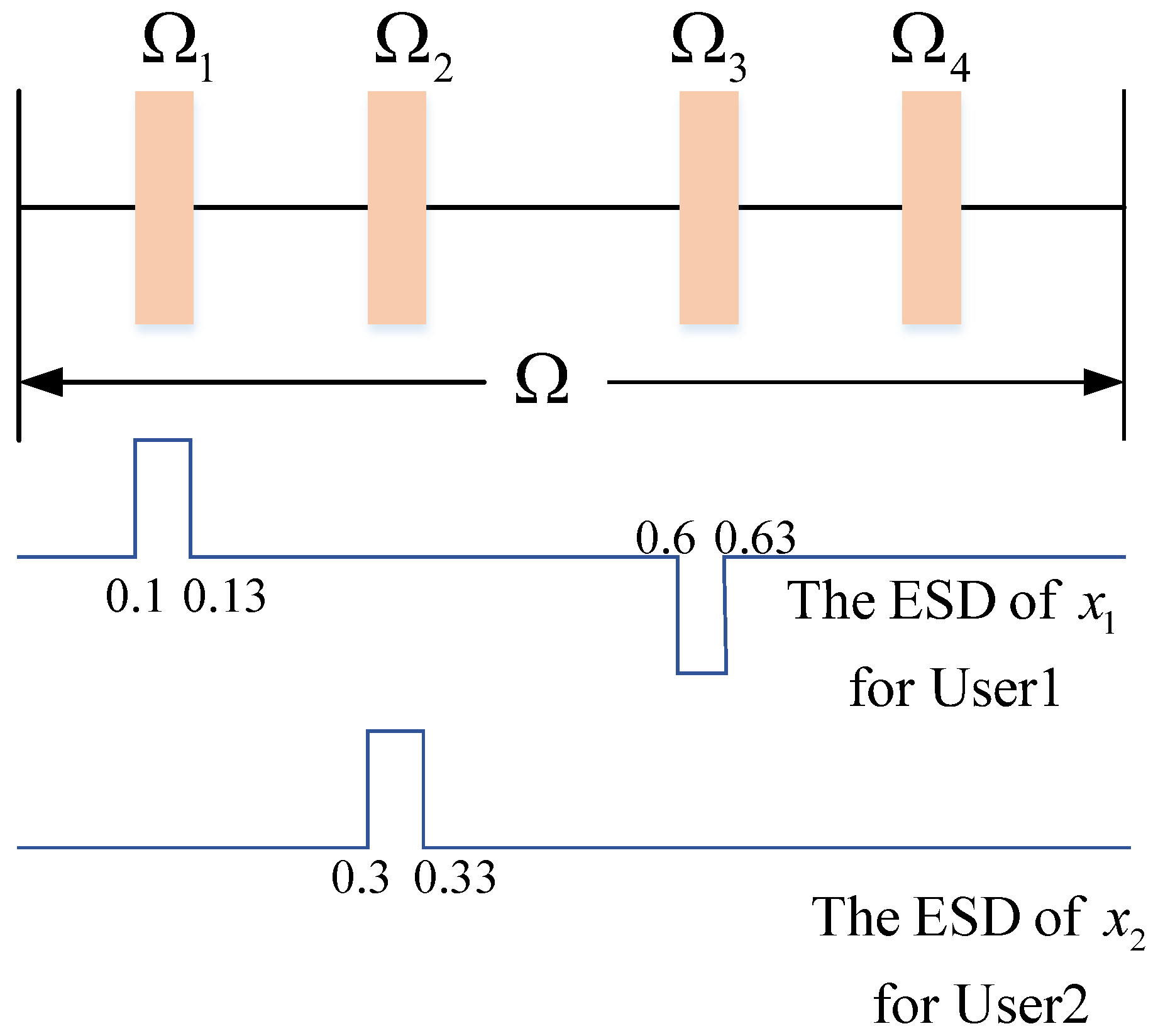
An example is given in the following. Suppose that the MIMO-DFRC system transmits information to two users located in θ 1 , θ 2 . According to Equation (8), the spatially synthetic far-field baseband discrete signals can be obtained as x 1 = S a * θ 1 , x 2 = S a * θ 2 . Then, frequency subband sets used to transmit information are (Without loss of generality, we assume L 1 = L 2 )
L 1 : = { Ω 1 1 , Ω 2 1 , , Ω L 1 } = { ( 0.1 , 0.13 ) , ( 0.3 , 0.33 ) , ( 0.6 , 0.63 ) , ( 0.8 , 0.83 ) } L 2 : = { Ω 1 2 , Ω 2 2 , , Ω L 2 } = { ( 0.1 , 0.13 ) , ( 0.3 , 0.33 ) , ( 0.6 , 0.63 ) , ( 0.8 , 0.83 ) }
Assuming Q 1 = 2 positions are selected from L 1 to deliver information to user 1, six possible selection patterns are
L 1 ( 1 ) = { ( 0.1 , 0.13 ) , ( 0.3 , 0.33 ) } , L 1 ( 2 ) = { ( 0.1 , 0.13 ) , ( 0.6 , 0.63 ) } , L 1 ( 3 ) = { ( 0.1 , 0.13 ) , ( 0.8 , 0.83 ) } , L 1 ( 4 ) = { ( 0.3 , 0.33 ) , ( 0.6 , 0.63 ) } , L 1 ( 5 ) = { ( 0.3 , 0.33 ) , ( 0.8 , 0.83 ) } , L 1 ( 6 ) = { ( 0.6 , 0.63 ) , ( 0.8 , 0.83 ) } .
According to Equation (12), the maximum number of transmitted bits is D 1 , 1 = 2 . Without losing generality, L 1 ( 1 ) , L 1 ( 2 ) , L 1 ( 3 ) , L 1 ( 6 ) are selected to convey binary sequence “00”, “01”, “10” and “11”, respectively. Furthermore, the amplitudes of selected subbands can also be used to embed information. Specifically, the conveyed binary data are “1” when the subband is a stopband; otherwise, the data are “0" for a passband. Figure 2 shows the subband selection and the energy control of selected subbands when the binary sequence “0101” is transmitted to user 1. In more detail, L 1 ( 2 ) = { ( 0.1 , 0.13 ) , ( 0.6 , 0.63 ) } is used to transmit the first two bits of “0101”. Ω 1 1 = ( 0.1 , 0.13 ) is enforced as a passband to transmit the third bit “0” and Ω 1 1 = ( 0.6 , 0.63 ) is enforced as a stopband to transmit the third bit “1”.
Similarly, assuming Q 2 = 1 position is selected from L 2 to deliver information to user 2, four possible selection patterns are
L 2 ( 1 ) = { ( 0.1 , 0.13 ) } , L 2 ( 2 ) = { ( 0.3 , 0.33 ) } , L 2 ( 3 ) = { ( 0.6 , 0.63 ) } , L 2 ( 4 ) = { ( 0.8 , 0.83 ) } .
Generally, L 2 ( 1 ) , L 2 ( 2 ) , L 2 ( 3 ) , L 2 ( 4 ) represent binary sequence “00”, “01”, “10” and “11”, respectively. Figure 2 also shows the subband selection and the energy control of selected subbands when the binary sequence “010” is transmitted to user 2. Specifically, L 2 ( 2 ) = { ( 0.3 , 0.33 ) } is used to transmit the first two bits of “010”. Ω 2 2 = ( 0.3 , 0.33 ) is enforced as a passband to transmit the third bit “0”.

2.1.2. Spectral Position Index and Amplitude Demodulation

The communication demodulation method is discussed in this subsection. Assuming that the channel state information is known, the baseband signal received by the user c located in θ c is
x ˜ c = β c S a * θ c + n c ,
where β c is the channel coefficient. n c C M × 1 denotes the additive Gaussian white noise vector with zero mean and variance δ c 2 .
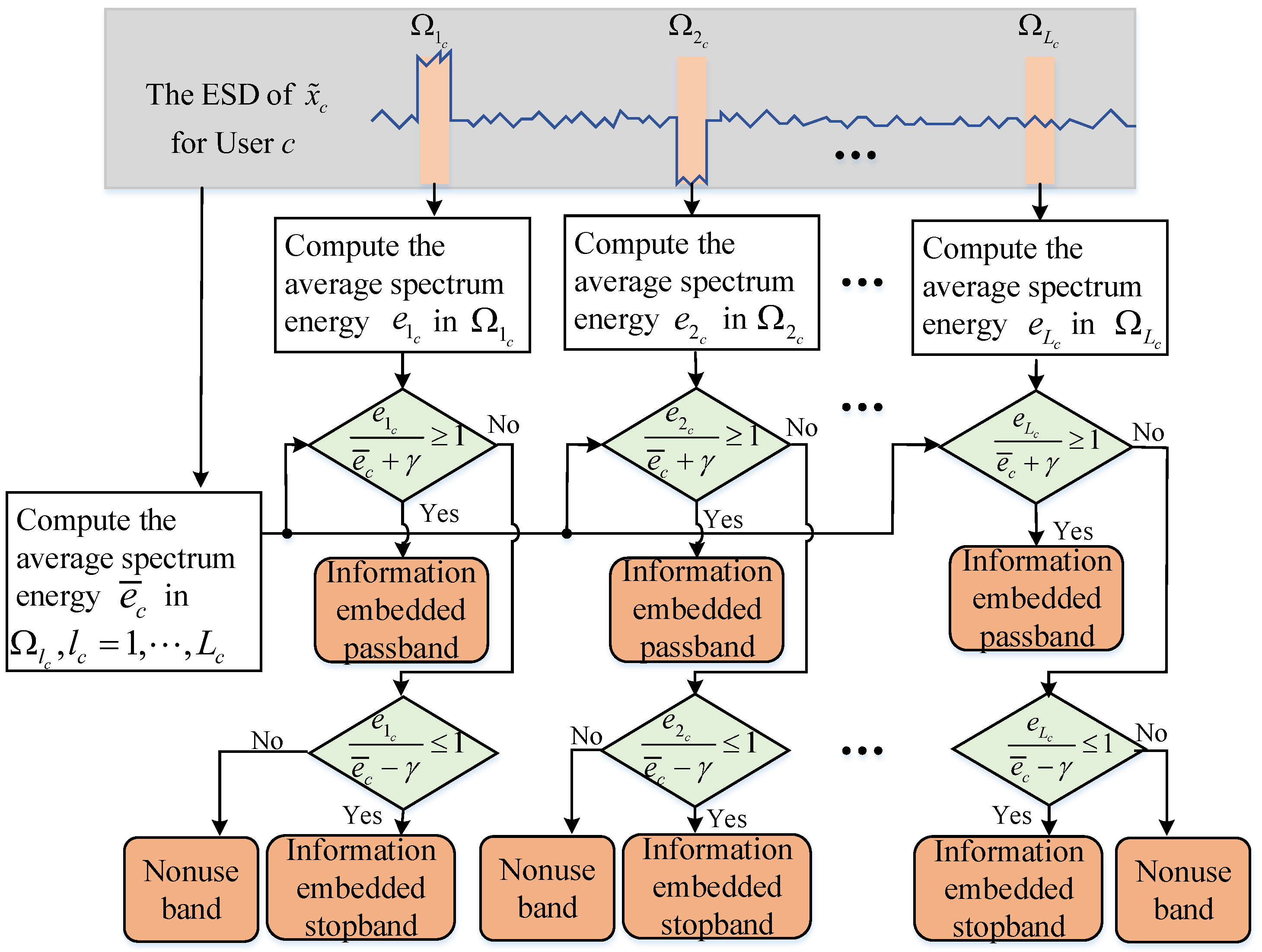
The frequency subband energy of the received signal x ˜ c is utilized to demodulate the information. In more detail, we performed K points Discrete Fourier Transformation (DFT) of the signal x ˜ c and then calculated the energy e l c (in dB) corresponding to each subband Ω l c = ( f l c , 1 , f l c , 2 ) , l c = 1 , , L c , given by [12]
e l c = 10 lg ( x ^ c H F l c F l c H x ^ c / N l c ) ,
where x ^ c = [ x ^ c T , 0 K M T ] T C K . F l c C K × ( N l c + 1 ) represents the DFT matrix, the n l c -th column of F l c is [ 1 , e j 2 π f l c n l , , e j 2 π f l c n l ( K 1 ) ] T , f l c n l = f l c , 1 + ( n l c 1 ) 2 π / K , n l c = 1 , , N l c + 1 , N l c = f l c , 2 f l c , 1 2 π / K .
The average energy of all selected sub-bands is
e ¯ c = l = 1 L c e l c / L c .
Then, the double threshold is set as e ¯ c + γ and e ¯ c γ , where γ is a small positive constant. If e l c > e ¯ c + γ , the subband is detected as a passband. Similarly, if e l c < e ¯ c γ , the subband is detected as a stopband. As a result, the positions and amplitudes of subbands used to embed information are detected. The information demodulation procedure is shown in Figure 3.

2.2. Problem Formulation

In this section, we formalize the dual-function signal design optimization problem via the maximization of the SINR with communication modulation, mainlobe level, sidelobe level and variable modulus constraints.

2.2.1. Waveform Design Metric

Since a higher SINR provides a better radar detection performance, the DFRC signal design is pursued to maximize SINR in this paper. According to Equations (5) and (7), SINR at the output of the receiver is written as
SINR = δ 0 2 a t H ( θ 0 ) R a t ( θ 0 ) p = 1 P δ p 2 a t H ( φ p ) R a t ( φ p ) + δ 2 ,
where δ 2 = M N t δ v 2 is the noise power. It can clearly be seen that the calculation of SINR needs the priori information of target location, target echo power, clutter location, clutter power, and noise power. These parameters can be acquired by exploiting a cognitive paradigm [39,40].

2.2.2. Waveform Constraints

(1) Communication Modulation Constraint: Assume that Q c subbands are selected to transmit information to user c. Specifically, let Ω q c = ( f q c , 1 , f q c , 2 ) L c , q c = 1 , , Q c , the subband energy for the user c can be expressed as
E c = q c = 1 Q c α q c x c H R q c x c = q c = 1 Q c α q c a T ( θ c ) S H R q c S a * ( θ c ) ,
therein, the ( m , n ) -th element of R q c is [40,41,42,43]
R q c ( m , n ) = e j 2 π f q c , 2 ( m n ) e j 2 π f q c , 1 ( m n ) j 2 π ( m n ) , m n f q c , 2 f q c , 1 , m = n ,
where α q c { 0 , 1 } is the weighted factor of the q c -th subband.
As tr [ AXB X T C ] = vect ( X ) T ( B T CA ) vect ( X ) [44], we can obtain
E c = q c = 1 Q c α q c s H [ R q c H ( a ( θ c ) a H ( θ c ) ) ] s ,
where s = vec { [ s 1 , s 2 , , s N t ] T } C N t M .
Further, the total spectral stopband energy of C users is
E s = c = 1 C E c = s H R s s ,
where the value of α q c obeys the following rule if the q c -th subband is stopband, α q c = 1 ; otherwise, α q c = 0 and
R s = c = 1 C q c = 1 Q c α q c [ R q c H ( a ( θ c ) a H ( θ c ) ) ] .
To communicate effectively, the stopband constraint is enforced, as given by [12]
s H R s s η s ,
where η s is the upper bound of energy.
Similarly, the spectral passband energy for the user c is
E p c = s H R c s ,
where the value of α q c obeys the following rule if the q c -th subband is passband, α q c = 1 ; otherwise, α q c = 0 and
R c = q c = 1 Q c α q c [ R q c H ( a ( θ c ) a H ( θ c ) ) ] .
For reliable communication, the spectral passband energy constraint for each user is enforced, as given by [12]
η p c s H R c s , c = 1 , , C ,
where η p c is the lower bound of transmitting energy for the user c.
(2) Integrated Sidelobe Level (ISL) Constraint: To reduce the echo intensity in non-target directions, the beampattern ISL constraint is enforced. ϑ k , k = 1 , , K ¯ and ϕ k , k = 1 , , K ˜ denote the mainlobe region and the sidelobe region, respectively. Therefore, the beampattern ISL is formulated as [12]
s H A s s s H A m s ε ,
where A s = 1 M k = 1 K ˜ I M [ a ( ϕ k ) a H ( ϕ k ) ] , A m = 1 M k = 1 K ¯ I M [ a ( ϑ k ) a H ( ϑ k ) ] , and ε is the upper bound.
(3) Mainlobe Width Constraint: We can enforce the mainlobe width constraint to concentrate energy in a specific area of space, as [12]
P L δ s H A k s s H A 0 s P L + δ , k = 1 , 2 ,
where A k = I M [ a ( θ m k ) a H ( θ m k ) ] / M . Φ ( θ m 2 θ m 0 θ m 1 ) denotes the main-beam width, P L 0 , 1 , and δ is a small positive value.
(4) Variable Modulus Constraint: To mitigate the effects of signal nonlinear distortion, the variable modulus constraint [45,46] is enforced as follows
1 N t κ | s n ( m ) | 2 1 N t + κ ,
where 1 N t κ and 1 N t + κ are the upper and lower bounds, respectively, and κ is a small positive constant. The above constraint degrades into a constant-envelop constraint when κ = 0 .

2.2.3. Waveform Design Problem

To ensure a good detection performance while enabling multi-user communication, we constructed the following optimization problem, which maximizes SINR with several practical constraints,
P 1 max s s H X 0 s s H Y 0 s s . t . s H A s s s H A m s ε , s H R s s η s , η p c s H R c s , c = 1 , , C , P L δ s H A k s s H A 0 s P L + δ , k = 1 , 2 , 1 N t κ | s n ( m ) | 2 1 N t + κ .
Therein, A 0 = I M [ a ( θ 0 ) a H ( θ 0 ) ] / M , A p = I M [ a ( φ p ) a H ( φ p ) ] / M , X 0 = δ 0 2 A 0 , Y 0 = p = 1 P δ p 2 A p + I M N t δ v 2 N t .
Since both the objective function and the feasible domain are non-convex, P 1 is a non-convex NP-hard problem. Next, we introduce an iterative algorithm.

2.3. Optimization Technique via IBE-DSADMM for Solving P 1

To solve the NP-hard optimization problem P 1 , firstly, we split the original non-convex NP-hard problem into the smaller subproblems using via the Iterative Block Enhancement (IBE) framework. Then, the DSADMM algorithm, via jointing Dinkelbach’s Iterative Procedure (DIP), Sequential Convex Approximation (SCA) and Alternating Direction Method Of Multipliers (ADMM), is used to solve the subproblems. Finally, DSADMM is incorporated into the IBE framework to form the IBE-DSADMM algorithm to monotonically increase SINR. The convergence and computational complexity are analyzed.

2.3.1. IBE-DSADMM Algorithm

This subsection presents the IBE-DSADMM algorithm to solve P 1 . Firstly, the IBM framework orderly optimizes f ( s 1 , , s N t ) over one block variable (e.g., s n ) in ( s 1 , , s N t ) , keeping the others fixed. Let s n ( i ) be the i-th optimized signal transmitted via n-th antenna, n = 1 , , N t . Therefore, in the i-th iteration, the following non-convex subproblems need to be solved:
P s n ( i ) max s n f ( s 1 ( i ) , , s n 1 ( i ) , s n , s n + 1 ( i 1 ) , , s N ( i 1 ) ) s . t . s n S n ( i ) ,
where S n ( i ) is the feasible set of s n at the i-th iteration.
Then, the DSADMM algorithm is utilized to handle Problem s n ( i ) . Before proceeding, Problem (34) is equivalently transformed into
P s n ( i ) max s n f ( s n ; s ¯ n ( i ) ) s . t . s n H A s n s n + a s n H s n + a s n ε s n H A m n s n + a m n H s n + a m n s n H R s n s n + s s n H s n + r s n 0 , η p c s n H R c n s n + r c n H s n + r c n , c = 1 , , C , ( P L δ ) ( s n H A 0 n s n + a 0 n H s n + a 0 n ) ( s n H A k n s n + a k n H s n + a k n ) 0 , k = 1 , 2 , ( s n H A k n s n + a k n H s n + a k n ) ( P L + δ ) × ( s n H A 0 n s n + a 0 n H s n + a 0 n ) 0 , k = 1 , 2 , | s n ( m ) | 2 1 N t + κ , 1 N t κ | s n ( m ) | 2 ,
where f ( s n ; s ¯ n ( i ) ) = s n H X n s n + x n H s n + x n s n H Y n s n + y n H s n + y n .
Proof. 
See Appendix A for the derivation.    □
Nevertheless, P s n ( i ) is still a non-convex problem. A parameter w is introduced to transform the objective function f ( s n ; s ¯ n ( i ) ) into the following representation,
χ ( y , s n ) = f 0 ( s n ) w f 1 ( s n ) ,
where f 0 ( s n ) = s n H X n s n + x n H s n + x n and f 1 ( s n ) = s n H Y n s n + y n H s n + y n . Therefore, the problem is rewritten as
max w s n χ ( w , s n ) s . t . { s n } S n ( i ) ,
w ( t ) and s n ( t ) denote the t-th iteration solutions. Invoking DIP method, Problem (35) is equivalent to
  • Given s n ( t 1 ) and w ( t ) = f 0 ( s n ( t 1 ) ) / f 1 ( s n ( t 1 ) ) .
  • Given w ( t ) , s n ( t ) is updated by solving
    max s n χ ( w ( t ) , s n ) s . t . { s n } S n ( i ) .
  • Repeat the above steps until convergence.
Unfortunately, Problem (36) is still non-convex. Leveraging the SCA algorithm, we can approximately recast this to a convex problem
P s n ( t ) max s n s n H D n s n + d n H s n + d n s . t . s n H B n s n + b n H s n + b n 0 , s n H R s n s n + r s n H s n + r s n 0 , s n H A ¯ k n s n + a ¯ k n H s n + a ¯ k n 0 , k = 1 , 2 , s n H A ˜ k n s n + a ˜ k n H s n + a ˜ k n 0 , k = 1 , 2 , r ¯ c n H s n + r ¯ c n 0 , c = 1 , , C , s n ( m ) H s n ( m ) 1 / N t κ 0 , m = 1 , , M p ¯ 1 s n ( m ) + p ¯ 2 0 , m = 1 , , M
Proof. 
See Appendix B for the derivation.    □
Finally, the ADMM algorithm is used to solve P s n ( t ) . By introducing auxiliary variables { h c ¯ } , { v c } , z , the problem P s n ( t ) is transformed into
min h , { h c ¯ } , { v c } , z h H D n h d n H h d n s . t . h 1 = h , h 1 H R s n h 1 + r s n H h 1 + r s n 0 , h 2 = h , h 2 H B n h 2 + b n H h 2 + b n 0 , h k = h , k = 3 , 4 , h k H A ¯ k 0 n h k + a ¯ k 0 n H h k + a ¯ k 0 n 0 h k ¯ = h , k ¯ = 5 , 6 , h k ¯ H A ˜ k 1 n h k ¯ + a ˜ k 1 n H h k ¯ + a ˜ k 1 n 0 v c = h , c = 1 , , C , r ¯ c n H v c + r ¯ c n 0 , z = h , z ( m ) H z ( m ) 1 / N t κ 0 , m = 1 , , M p ¯ 1 z ( m ) + p ¯ 2 0 , m = 1 , , M
where k 0 = k 2 , k 1 = k ¯ 4 . The augmented Lagrangian of the above problem is constructed as follows [47]:
L ϱ ( h , { h c ¯ } , { v c } , z , { μ c ¯ } , { μ c } , μ z ) = h H D n h d n H h d n + c ¯ = 1 6 ϱ / 2 h c ¯ h + μ c ¯ / ϱ 2 + c = 1 C ϱ / 2 v c h + μ c / ϱ 2 + ϱ / 2 z h + μ z / ϱ 2
where { μ c ¯ } , { μ c } , μ z are dimensional multiplier vectors and ϱ > 0 is the penalty parameter.
We minimize L ϱ ( h , { h c ¯ } , { v c } , z , { μ c ¯ } , { μ c } , μ z ) via the ADMM algorithm. See Appendix C for details of the algorithm.
Finally, the procedure of the IBE-DSADMM algorithm is reported in Algorithm 1.
Algorithm 1: IBE-DSADMM for P 1
Input:  Feasible starting point s 0 ;
Output:  An optimized solution s ( * ) to P 1 ;
  1:
For i = 0 , initialize s ( i ) = s 0 and calculate f ( s 1 ( i ) , , s N ( i ) ) ;
  2:
i : = i + 1 , n = 0 ;
  3:
n : = n + 1 ;
  4:
t = 0 ,   s n ( t ) = s n ( i 1 ) ;
  5:
t = t + 1 ;
  6:
Calculate w ( t ) = f 0 ( s n ( t 1 ) ) / f 1 ( s n ( t 1 ) ) , D n and d n ;
  7:
Find an optimal solution s n ( t ) * to P s n ( t ) by using ADMM;
  8:
If | y ( t ) y ( t 1 ) | κ 1 , s n ( i ) = s n ( t ) * ; Otherwise, go to Step 5;
  9:
If n < N , go to Step 3;
 10:
If | f ( s 1 ( i 1 ) , , s N ( i 1 ) ) f ( s 1 ( i ) , , s N ( i ) ) | κ 2 , output s ( ) = s ( i ) ; Otherwise, go to Step 2.

2.3.2. Algorithm Initialization

An initial feasible point s 0 is necessary to start Algorithm 1. Thus, the following problem is introduced to find s 0
P s find s s . t . s H A s s s H A m s ε , s H R s s η s , η p c s H R c s , c = 1 , , C , P L δ s H A k s s H A 0 s P L + δ , k = 1 , 2 , 1 N t κ | s ( n ) | 2 1 N t + κ , , n = 1 , , M N t .
Similarly, the non-convex constraints in Problem (39) are replaced with their first-order conditions. Meanwhile, some slack variables are introduced to ensure the feasibility [48]. Specifically, ➀ is a convex constraint if A s ε A m . Otherwise, it is approximated as s H A s s ε s ¯ H A m s ¯ + 2 s ¯ H A m ( s s ¯ ) 0 , where s ¯ is the previous iteration solution. Follow the same method for the other constraints. Thus, Problem (39) is approximated as a convex problem as follows
min s , b ¯ , { b c } , { b c ˜ } ρ ¯ [ c = 1 C b c + c ˜ = 1 5 b c ˜ + b ¯ ] s . t . s H R s s η s , r ¯ c H s + r ¯ c b c 0 , b c 0 , c = 1 , , C , s H A ¯ s s + a ¯ s H s + a ¯ s b c ˜ 0 , b c ˜ 0 , c ˜ = 1 , s H A ¯ k s + a ¯ k H s + a ¯ k b c ˜ 0 , b c ˜ 0 , c ˜ = 2 , 3 , s H A ˜ k s + a ˜ k H s + a ˜ k b c ˜ 0 , b c ˜ 0 , c ˜ = 4 , 5 , s ( n ) H s ( n ) 1 / N t κ 0 , n = 1 , , M N t q ¯ 1 s ( n ) + q ¯ 2 b ¯ 0 , b ¯ 0 ,
where b ¯ , { b c } , { b c ˜ } are slack variables. ρ ¯ is a large enough positive number to penalize slack variables approaching zero. r ¯ c = 2 R c s ¯ , r ¯ c = η p c + s ¯ R c s ¯ , q ¯ 1 = 2 s ¯ ( n ) , q ¯ 2 = 1 / N t κ + s ¯ ( n ) H s ¯ ( n ) . If constraints ➀ and ➃ are convex, A ¯ s = A s ε A m , A ¯ k = ( P L δ ) A 0 A k , A ˜ k = A k ( P L + δ ) A 0 , a ¯ s = 0 , a ¯ k = 0 , a ˜ k = 0 , a ¯ s = 0 , a ¯ k = 0 , a ˜ k = 0 . Otherwise, A ¯ s = A s , A ¯ k = ( P L δ ) A 0 , A ˜ k = A k , a ¯ s = 2 ε A m s ¯   a ¯ k = 2 A k s ¯ , a ˜ k = 2 ( P L + δ ) A 0 s ¯ , a ¯ s = ε ( s ¯ H A m s ¯ ) , a ¯ k = s ¯ H A k s ¯ , a ˜ k = ( P L + δ ) ( s ¯ H A 0 s ¯ ) . We solve the above convex problem using the CVX toolbox.

2.3.3. Computational Complexity

The computational complexity of IBE-DSADMM mainly depends on two factors. One is the iteration of variables x n , y n , a s n , a m n , r s n , r c n , a k n , a 0 n , with a computational complexity of O ( ( N t M ) 2 ) . Another is the complexity of ADMM for solving P s n ( t ) (e.t. O ( L A T D M 2 ) ). Therein, L A and T D are the iteration times of ADMM and DIP algorithms, respectively. Thus, the total computational complexity is O ( I B N t 3 M 2 ) + O ( I B L A T D N t M 2 ) + O ( N t M 3 ) for IBE-DSADMM, where I B is the iteration time of the whole algorithm. O ( N t M 3 ) is the cost of the matrix inversion of D n .

2.3.4. Convergence Analysis

We analyze the convergence of the IBE-DSADMM algorithm in this subsection.
(1) The ADMM algorithm decomposes P s n ( t ) into multiple convex subproblems with closed-form solutions.
(2) The DSADMM algorithm ensures that the w ( t ) sequence is monotonically increasing to convergence [12].
(3) According to the IBE framework, it follows that
f ( s 1 ( i 1 ) , , s N ( i 1 ) ) f ( s 1 ( i ) , s 2 ( i 1 ) , , s N ( i 1 ) ) f ( s 1 ( i ) , , s N 1 ( i ) , s N ( i 1 ) ) f ( s 1 ( i ) , , s N 1 ( i ) , s N ( i ) ) ,
which implies that the objective function value increases monotonically with iterations. In addition, the upper bound of f ( s 1 , , s N ) is the maximum eigenvalue of matrix Y 0 1 X 0 . Thus, the objective function increases monotonically to convergence.

3. Results

This section evaluates the performance of the proposed SPIA modulation method in terms of detection performance and communication performance. To highlight the superiority of the IBE-DSADMM algorithm, the IBE-DSIPM algorithm [49] is introduced as a benchmarker, which uses the Interior Point Method (IPM) algorithm instead of the ADMM algorithm to solve optimization problems.
Unless otherwise stated, Table 1 shows the parameter settings.

3.1. Beampattern Performance

We aim to analyze the beampattern performance of the IBE-DSADMM algorithm considering different η p 1 and κ for communication passband modulation and variable modulus constraints in this subsection. The influence of information embedding subband number Q 1 is also considered.
Q 1 = 4 subbands were selected for information embedding in Figure 4. In moredetail, the Q 1 = 4 subbands were set as Ω 5 1 = ( 0.5 , 0.53 ) , Ω 6 1 = ( 0.6 , 0.63 ) , Ω 7 1 = ( 0.7 , 0.73 ) , Ω 9 1 = ( 0.9 , 0.93 ) , respectively, and the bit sequence “0101” was transmitted by amplitude modulation. Figure 4a shows SINRs (in dB) versus iteration number for η p 1 = 2 , κ = 0.0001 , 0.05 . It can be observed that the SINRs (in dB) increase monotonously along with the iteration for both IBE-DSADMM and IBE-DSIPM algorithms. Moreover, the two algorithms share a converged SINR value. This is reasonable because the ADMM algorithm can obtain the optimal solution to the convex problem P s n ( t ) . The corresponding SINRs (in dB) versus iteration time are also depicted in Figure 4b. It is worth mentioning that the IBE-DSADMM algorithm converges faster than the IBE-DSIPM algorithm. Finally, it is obvious that the larger κ , the larger the obtained converged SINR value owning to the enlarged feasible set on P 1 . Figure 4c reports SINRs’ (in dB) value against iteration number for η p 1 = 2 , 5 , κ = 0.05 . The results again exhibit that IBE-DSADMM and IBE-DSIPM obtain near-converged SINR values. Figure 4d also depicts the corresponding SINRs value versus CPU time. The results again demonstrate the advantage of the IBE-DSADMM algorithm in terms of convergence speed. Finally, the curves also show that the smaller the η p 1 , the higher the converged SINR value will be owing to there being more DoFs on P 1 .
In Figure 4e, the beampatterns vesus angle are depicted for η p 1 = 2 , κ = 0.0001 , 0.05 . The results show all optimized beampatterns have a high sidelobe level around the communication direction 70 . The reason for this is that more energy is required to transmit to communication users, which is located in the sidelobe domain. Furthermore, the optimized SINR guarantees the maximum radiation power of the target direction (i.e., θ 0 = 15 ) and the minimum radiation energy of clutter directions (i.e., 30 and 60 ), which enhances the target detection and clutter suppression capability. The results in Figure 4e are consistent with the previous Figure 4a,b. Specifically, the larger the κ , the better the beampattern performance will be. Figure 4f illustrates the normalized beampatterns obtained for η p 1 = 2 , 5 , κ = 0.05 . it is clearly observed that beampattern nullings are formed in clutter directions (i.e., 30 and 60 ). In addition, these curves highlight again that IBE-DSADMM and IBE-DSIPM have an almost identical beampattern and the smaller the η p 1 value, the better the obtained beampattern performance.
The impact of information embedding subbands number Q 1 is analyzed in Figure 5. The parameters are set as η p 1 = 2 , κ = 0.05 with Q 1 = 2 , 3 , 4 . We chose 250 information embedding subband position selection patterns. Figure 5a shows the specific converged SINR values of the aforementioned 250 trails. It is clearly seen that the converged SINR values fluctuate within a very small range. The normalized beampatterns versus angle with the maximum converged SINR values are depicted in Figure 5b. The results again exhibit that different Q 1 share closely converged SINR values, which is consistent with Figure 5a.

3.2. Communication Performance

The communication performance of the proposed SPIA modulation method is discussed in this subsection. Figure 6a illustrates Symbol Error Ratio (SER) versus Power Noise Ratio (PNR) with η p 1 = 2 , 5 , κ = 0.05 , 0.0001 , Q 1 = 2 , 4 . According to the based band echo x ˜ c in (17), the PNR received by the c-th user is defined as | β c | 2 / δ c 2 . The curves show that the larger the η p 1 , the smaller the SER will be due to more energy being transmitted to communication users. In addition, a smaller κ leads to a higher sidelobe level in communication direction, which also results in a lower SER. Nevertheless, an increase in η p 1 and a decrease in κ raise the sidelobe level, which may degrade the detection performance. The results indicate that careful selection of η p 1 and κ is needed to balance radar detection with SER performance. Figure 6a also reveals that a smaller Q 1 leads to a better SER performance as preciser demodulation is performed. Note that although Figure 5 shows that a different Q 1 almost cannot affect SINR performance, a trade-off between data rate and SER performance also exists. Figure 6b–d shows the optimized frequency band energy (in dB) towards communication users with selected Q = 2 , 3 , 4 subbands for information embedding, respectively. The curves highlight that the passbands and stopbands are formed in the accurate position corresponding to the delivered bit sequence.

3.3. Performance Analysis for Different Application Scenarios

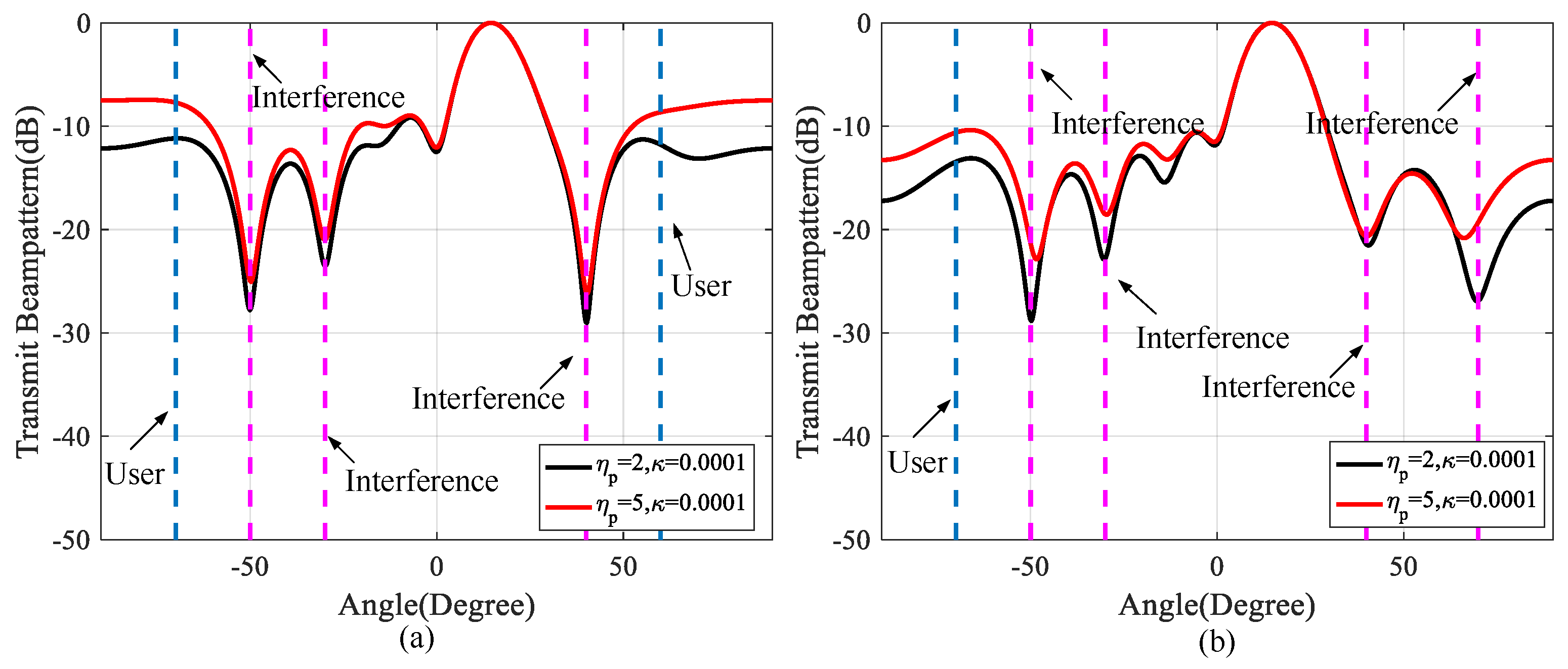
This subsection evaluates the performance of the proposed SPIA modulation method for different application scenarios. Specifically, we consider different numbers of communication users and interfering sources. The signal-dependent interfering sources are assumed to be in the same range bin with the target. Figure 7a,b show optimized beampatterns with two users and three interfering sources and one user and four interfering sources, respectively. It can be seen that the energy could be focused near the target direction and beampattern nullings are formed in clutter directions. In addition, a higher sidelobe level is achieved with increasing η p 1 .

3.4. Comparison with Related Information Embedding Methods

In this section, we compare the proposed SPIA modulation method with the sidelobe modulation [9] and our previous work, named spatio-spectral modulation [12].
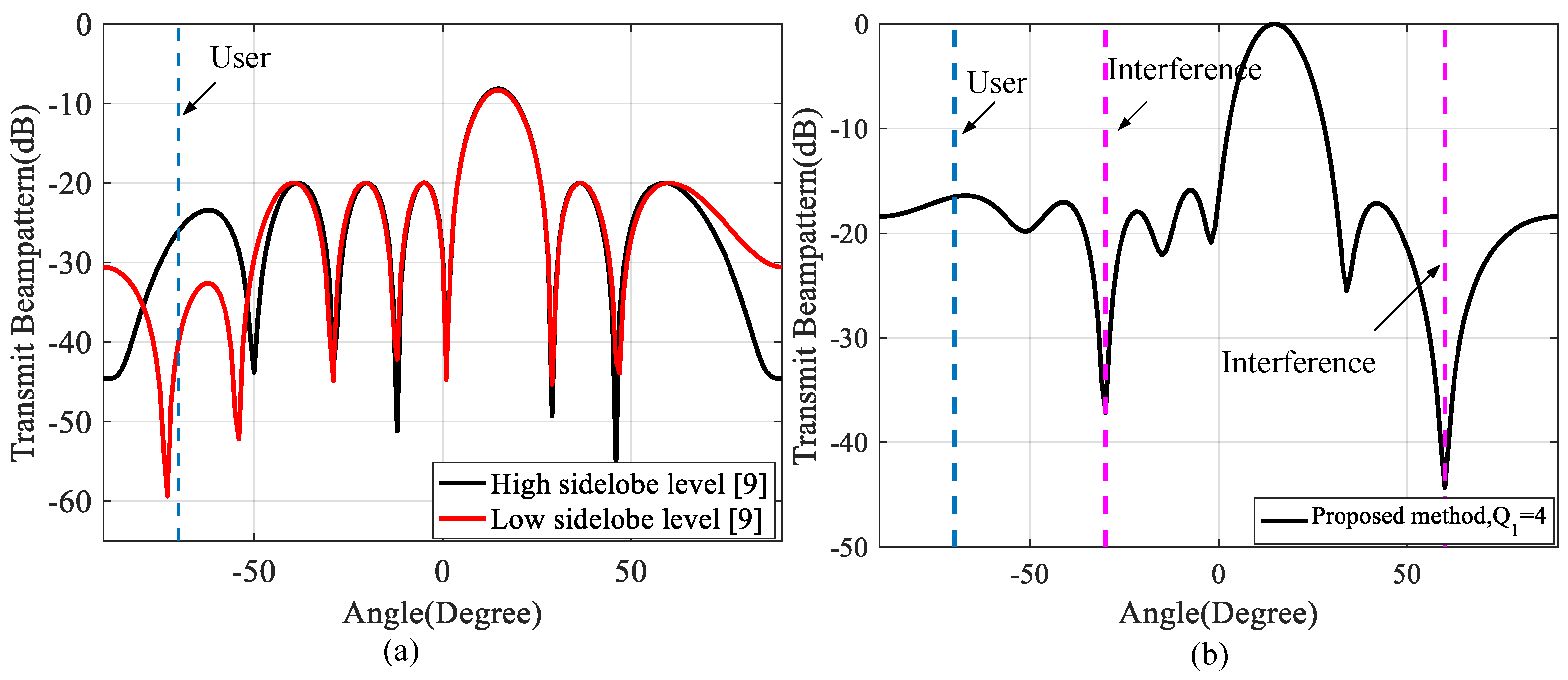
In [9], the focus is on the design of joint transmit weight vectors and the utilization of signal diversity to introduce variations in the sidelobe levels (SLLs) for communication. The number of orthogonal signals used is equal to the number of bits being transmitted. By controlling the sidelobes in the communication directions, two distinct levels can be achieved, requiring the use of two transmit beamforming weight vectors. The communication SLLs are enforced to be either 0.1 (−20 dB) or 0.01 (−40 dB). Parameters such as array type, antenna spacing, antenna number, communication user direction, mainlobe region, and sidelobe region are the same as specified in Table 1. Figure 8a,b illustrate the beampatterns achieved through sidelobe modulation [9] and the proposed SPIA modulation method, respectively. The number of information embedding subbands in the SPIA modulation method, denoted as Q1, is set to 4. The results indicate that the beampattern performance of the proposed SPIA modulation method is superior to the sidelobe modulation method. The former method achieves its beampattern by matching it with an ideal mask pattern, while the latter maximizes the SINR. It is important to note that the proposed SPIA modulation method creates nullings in the direction of interference sources, which aids in clutter suppression. However, the former method does not take into account the presence of clutter. Additionally, the former method requires designing a specific orthogonal signal set size to meet the data rate requirements.
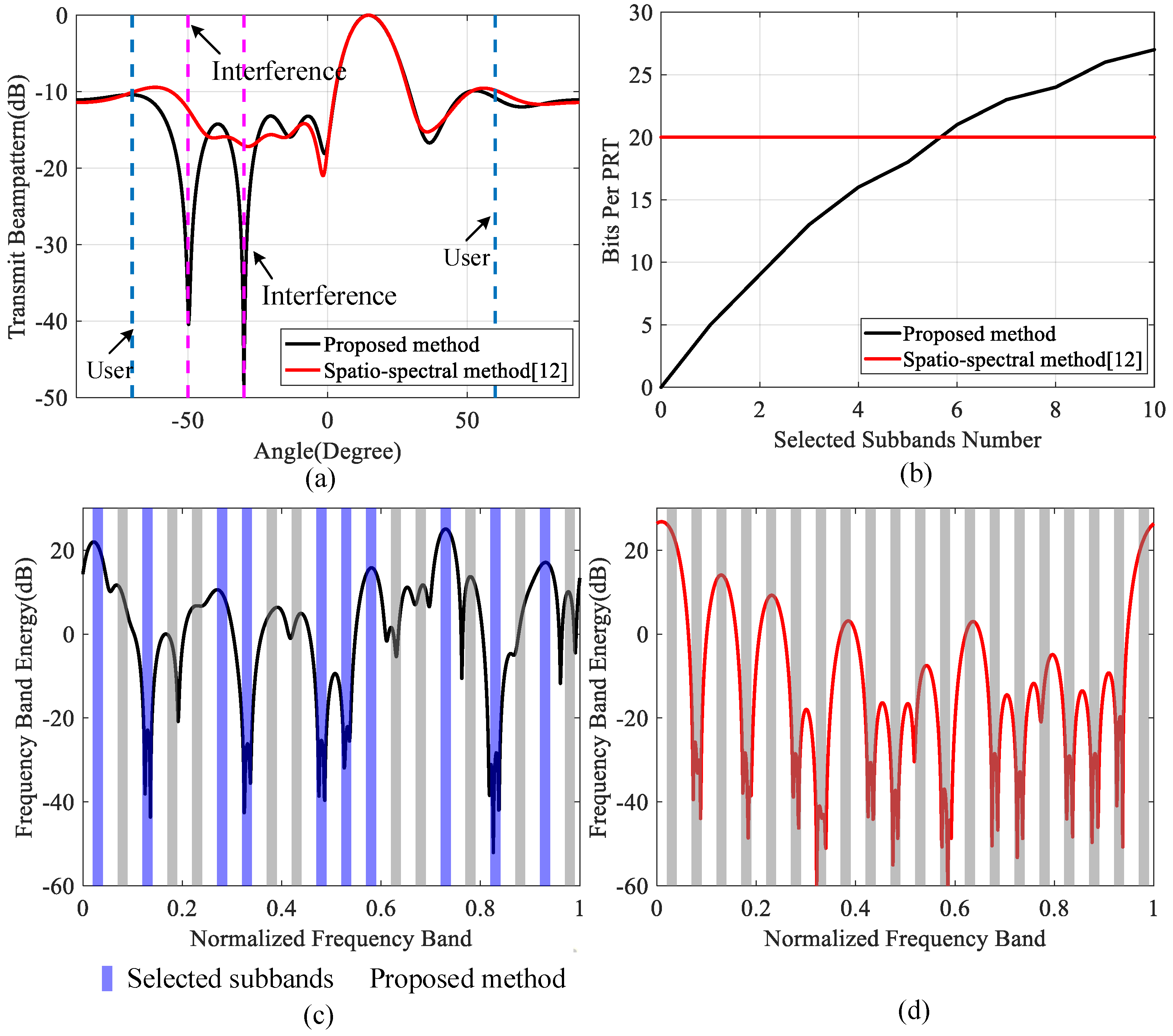
To highlight the superiority of the proposed SPIA modulation method, the spatio-spectral modulation [12] is taken as a benchmarker. The parameter settings are shown in Table 2. Figure 9a depicts the optimized beampatterns obtained by the proposed SPIA modulation method and spatio-spectral modulation [12], which delineates that the proposed SPIA modulation method can form the beampattern nullings in clutter directions. Figure 9b presents the number of bits transmitted in a PRT versus the number of selected information embedding subbands. Since the spatio-spectral modulation in [12] uses the energy of subbands to embed information. Thereby, the data rate is fixed in 20 bits per PRT when the available frequency subband number is 20. According to Equation(13), the data rate in the proposed SPIA method increases along with the number of selected information embedding subbands. Note that the proposed SPIA method provides a higher data rate than the spatio-spectral modulation in [12] when more than six subbands are selected. Figure 9c shows the optimized frequency band energy (in dB) towards communication user 1 using the proposed SPIA modulation method. Ten information subbands selected to embed information are formed by the corresponding passbands and stopbands. Figure 9d shows the optimized frequency band energy (in dB) towards communication user 1 via spatio-spectral modulation [12]. The curve highlights that all 20 available subbands are used to embed information.

4. Discussion

(1) A method for designing an MIMO DFRC signal is proposed to enhance signal detection and communication in the presence of signal-dependent clutter. The proposed method optimizes the beampattern to create nullings in clutter directions, effectively suppressing clutter based on prior knowledge of clutter locations. Additionally, the beam direction is optimized to precisely detect the target location, obtained through a cognitive paradigm. This ensures good detection performance.
(2) A novel modulation technique called SPIA modulation, which combines spectral passband and stop-band selection with amplitude modulation, is proposed to achieve simultaneous detection and communication. Unlike the existing approaches [32,33,34], the SPIA modulation methodology is proposed instead of using a conventional communication sequence. Additionally, previous works on DFRC signal design have focused on index modulation [14,15,16,17,18,19], primarily utilizing intra-pulse modulation without altering the conventional radar baseband signal. However, in this paper, we focus on index modulation via inter-pulse modulation, where the baseband signal is modified as an alternative to intra-pulse modulation. However, it is worth mentioning that, in future work, we plan to explore the combination of intra- and inter-pulse modulation techniques to design a dual-function signal.
(3) The IBE-DSADMM is exploited to solve the original nonconvex NP-hard problem. The algorithm guarantees that the SINR value monotonically increases and converges to a finite value.

5. Conclusions

In this paper, an MIMO DFRC signal design method resorting to SPIA modulation was proposed to realize radar detection and communication in signal-dependent clutter. To effectively suppress signal-dependent clutter and improve radar detection performance, SINR was used as the criterion to construct an optimization problem with practical constraints. We also exploited an IBE-DSADMM algorithm to monotonically increase the SINR. The numerical results verified that the designed integrated signal ensures the detection performance in the signal-dependent clutter and simultaneously implements multi-user communication.   

Author Contributions

Conceptualization, X.Y. (Xue Yao); Formal analysis, X.Y. (Xue Yao); Funding acquisition, X.N.; Investigation, B.P. and T.F.; Methodology, X.Y. (Xue Yao); Project administration, X.N.; Supervision, G.C.; Validation, X.Y. (Xianxiang Yu); Writing—original draft, B.P., T.F. and G.C.; Writing—review and editing, X.Y. (Xue Yao) and X.Y. (Xianxiang Yu). All authors have read and agreed to the published version of the manuscript.

Funding

The work was supported by the National Natural Science Foundation of China (62101097 and 62271126). Natural Science Foundation Project of Chongqing (2022NSCQ-MSX3815). National key research and development program (2021YFB3901400).

Acknowledgments

The authors appreciate the valuable comments and constructive suggestions from the anonymous referees and the editors who helped improve the manuscript.

Conflicts of Interest

The authors declare no conflict of interest.

Appendix A

Given s = vec ( [ s 1 , , s N ] T ) C N M , A N M , the quadratic function g s = s H As can be recast as a function of the specific block s n , i.e.,
g s n ; s ¯ n = ( s ¯ n + Λ n s n ) H A ( s ¯ n + Λ n s n ) = s n H Λ n H A Λ n s n + 2 s ¯ n H A Λ n s n + s ¯ n H A s ¯ n ,
where s ¯ n = s Λ n s n C N M , and Λ n C N M × M is defined as
Λ n ( i , j ¯ ) = 1 , if i = n + ( j ¯ 1 ) N 0 , otherwise
with i { 1 , , N M } , j ¯ { 1 , , M } , s n = vec ( [ s 1 , , s n 1 , s n + 1 , , s N ] T ) C ( N 1 ) M .
Let s ( n i ) = vect ( [ s 1 ( i ) , , s n 1 ( i ) , s n , s n + 1 ( i 1 ) , , s N t ( i 1 ) ] T ) C N t M , the objective function f ( s 1 ( i ) , , s n 1 ( i ) , s n , s n + 1 ( i 1 ) , , s N t ( i 1 ) ) can be rewritten as
f ( s n ; s ¯ n ( i ) ) = s n H X n s n + x n H s n + x n s n H Y n s n + y n H s n + y n ,
where X n = Λ n H X 0 Λ n , x n = 2 Λ n H X 0 H s ¯ n ( i ) and x n = s ¯ n ( i ) H X 0 s ¯ n ( i ) . Y n = Λ n H Y 0 Λ n , y n = 2 Λ n H Y 0 H s ¯ n ( i ) and y n = s ¯ n ( i ) H Y 0 s ¯ n ( i ) . s n ( i ) = vect ( [ s 1 ( i ) , , s n 1 ( i ) , s n + 1 ( i 1 ) , , s N t ( i 1 ) ] T ) C ( N t 1 ) M , s ¯ n ( i ) = s ( n i ) Λ n s n C N t M .
Constraint ➀ in Problem P 1 can be recast
s n H A s n s n + a s n H s n + a s n ε s n H A m n s n + a m n H s n + a m n
where A s n = Λ n H A s Λ n , a s n = 2 Λ n H A s H s ¯ n ( i ) and a s n = s ¯ n ( i ) H A s s ¯ n ( i ) , A m n = Λ n H A m Λ n , a m n = 2 Λ n H A m H s ¯ n ( i ) and a m n = s ¯ n ( i ) H A m s ¯ n ( i ) .
Constraint ➁ can be written to
s n H R s n s n + r s n H s n + r s n 0 ,
where R s n = Λ n H R s Λ n , r s n = 2 Λ n H R s H s ¯ n ( i ) , r s n = s ¯ n ( i ) H R s s ¯ n ( i ) η s .
Constraint ➂ can be rewritten to
η p c s n H R c n s n + r c n H s n + r c n , c = 1 , , C ,
where R c n = Λ n H R c Λ n , r c n = 2 Λ n H R c H s ¯ n ( i ) , r c n = s ¯ n ( i ) H R c s ¯ n ( i ) .
Constraint ➃ can be converted to
( P L δ ) s n H A 0 n s n + a 0 n H s n + a 0 n s n H A k n s n + a k n H s n + a k n , k = 1 , 2 ,
s n H A k n s n + a k n H s n + a k n ( P L + δ ) s n H A 0 n s n + a 0 n H s n + a 0 n , k = 1 , 2 ,
where A k n = Λ n H A k Λ n , a k n = 2 Λ n H A k H s ¯ n ( i ) , a k n = s ¯ n ( i ) H A k s ¯ n ( i ) , A 0 n = Λ n H A 0 Λ n , a 0 n = 2 Λ n H A 0 H s ¯ n ( i ) , a 0 n = s ¯ n ( i ) H A 0 s ¯ n ( i ) .

Appendix B

Next, we are going to find an approximation solution to Problem (36) by solving its approximation version. Interestingly, we observe the objective function χ ( w ( t ) , s n ) is the difference between two convex functions. To this end, the objective function can be approximated by a lower bound function. Specifically,
χ ( w ( t ) , s n ) s n ( t 1 ) H X n s n ( t 1 ) + 2 s n ( t 1 ) H X n ( s n s n ( t 1 ) ) + x n H s n + x n w ( t ) ( s n H Y n s n + y n H s n + y n ) = s n H D n s n + d n H s n + d n ,
where D n = w ( t ) Y n , d n = w ( t ) y n + 2 X n s n ( t 1 ) + x n , d n = w ( t ) y n s n ( t 1 ) H X n s n ( t 1 ) + x n .
Similarly, constraints ➀, ➃, ➄ are also the difference between two convex quadratic functions. Specifically, if A s n ε A m n , constraint ➀ is convex. Otherwise, it is approximated to [50,51]
( s n H A s n s n + a s n H s n + a s n ) ε s n ( t 1 ) H A m n s n ( t 1 ) + 2 s n ( t 1 ) H A m n ( s n s n ( t 1 ) ) + a m n H s n + a m n 0 .
A similar operation can be implemented on constraints ➃ and ➄.
As to constraint ➂, it can be approximated to
η p c s n ( t 1 ) H R c n s n ( t 1 ) + 2 s n ( t 1 ) H R c n ( s n s n ( t 1 ) ) + r c n H s n + r c n 0 .
And constraint ➆ is treated in the same way.
In this respect, we can approximately tackle the maximization of χ ( w ( t ) , s n ) through solving the following convex problem
P s n ( t ) max s n s n H D n s n + d n H s n + d n s . t . s n H B n s n + b n H s n + b n 0 , s n H R s n s n + r s n H s n + r s n 0 , s n H A ¯ k n s n + a ¯ k n H s n + a ¯ k n 0 , k = 1 , 2 , s n H A k n s n + a ˜ k n H s n + a ˜ k n 0 , k = 1 , 2 , r ¯ c n H s n + r ¯ c n 0 , c = 1 , , C , s n ( m ) H s n ( m ) 1 / N t κ 0 , m = 1 , , M p ¯ 1 s n ( m ) + p ¯ 2 0 , m = 1 , , M ,
where r ¯ c n = 2 R c n s n ( t 1 ) r c n , r ¯ c n = s n ( t 1 ) H R c n s n ( t 1 ) + η p c r c n , p ¯ 1 = 2 s n ( t 1 ) ( m ) , p ¯ 2 = 1 / N t κ + s n ( t 1 ) ( m ) H s n ( t 1 ) ( m ) . If constraints ➃ and ➄ are convex, B n = A s n ε A m n , A ¯ k n = ( P L δ ) A 0 n A k n , A ˜ k n = A k n ( P L + δ ) A 0 n , b n = a s n ε a m n , a ¯ k n = ( P L δ ) a 0 n a k n , a ˜ k n = a k n ( P L + δ ) a 0 n , b n = a s n ε a m n , a ¯ k n = ( P L δ ) a 0 n a k n , a ˜ k n = a k n ( P L + δ ) a 0 n . Otherwise, if constraints ➃ and ➄ are non-convex, B n = A s n , A ¯ k n = ( P L δ ) A 0 n , A ˜ k n = A k n , b n = a s n ε a m n 2 ε A m n s n ( t 1 ) , a ˜ k n = ( P L δ ) a 0 n a k n 2 A k n s n ( t 1 ) , a ˜ k n = a k n ( P L + δ ) ( 2 A 0 n s n ( t 1 ) + a 0 n ) , b n = a s n ε a m n + ε s n ( t 1 ) H A m n s n ( t 1 ) , a ¯ k n = ( P L δ ) a 0 n a k n + s n ( t 1 ) H A k n s n ( t 1 ) , a ˜ k n = a k n ( P L + δ ) ( a 0 n s n ( t 1 ) H A 0 n s n ( t 1 ) ) .

Appendix C

Assume that the l-th iteration results of h , z , { h c ¯ } , { v c } , { μ c ¯ } , { μ c } , μ z are respectively h ( l ) , z ( l ) , { h c ¯ ( l ) } , { v c ( l ) } , { μ c ¯ ( l ) } , { μ c ( l ) } , μ z ( l ) . The ADMM [52,53] procedure can be reported in Algorithm A1.
Algorithm A1: ADMM for solving P s n ( t )
Input:  h ( 0 ) , z ( 0 ) , { h c ¯ ( 0 ) } , { v c ( 0 ) } , { μ c ¯ ( 0 ) } , { μ c ( 0 ) } , μ z ( 0 ) ;
Output: An optimized solution s n ( t ) * to P s n ( t ) ;
  1:
l = 0 ;
  2:
l : = l + 1 ;
  3:
Update h ( l ) , z ( l ) , { h c ¯ ( l ) } , { v c ( l ) } , { μ c ¯ ( l ) } , { μ c ( l ) } , μ z ( l ) by solving the following problems:
h 1 ( l ) : = arg min h 1 h 1 h ( l 1 ) + μ 1 ( l 1 ) / ϱ 2 s . t . h 1 H R s n h 1 + r s n H h 1 + r s n 0 ,
h 2 ( l ) : = arg min h 2 h 2 h ( l 1 ) + μ 2 ( l 1 ) / ϱ 2 s . t . h 2 H B n h 2 + b n H h 2 + b n 0 ,
{ h k ( l ) } : = arg min { h k } k = 3 4 h k h ( l 1 ) + μ k ( l 1 ) / ϱ 2 s . t . h k H A ¯ n , k 0 h k + a ¯ n , k 0 H h k + a ¯ n , k 0 0 , k = 3 , 4 , k 0 = k 2 ,
{ h k ¯ ( l ) } : = arg min { h k ¯ } k ¯ = 5 6 h k ¯ h ( l 1 ) + μ k ¯ ( l 1 ) / ϱ 2 s . t . h k ¯ H A ˜ n , k 1 h k ¯ + a ˜ n , k 1 H h k ¯ + a ˜ n , k 1 0 , k ¯ = 5 , 6 , k 1 = k ¯ 4 ,
{ v c ( l ) } : = arg min { v c } c = 1 C v c h ( l 1 ) + μ c ( l 1 ) / ϱ 2 s . t . r ¯ c n H v c + r ¯ c n 0 , c = 1 , , C ,
z ( l ) : = arg min z z h ( l 1 ) + μ z ( l 1 ) / ϱ 2 s . t . z ( m ) H z ( m ) 1 / N t κ 0 , m = 1 , , M p ¯ 1 z ( m ) + p ¯ 2 0 , m = 1 , , M
h ( l ) : = arg min h L ϱ ( h , z ( l ) , { h c ¯ ( l ) } , { v c ( l ) } , { μ c ¯ ( l 1 ) } , { μ c ( l 1 ) } , { μ z ( l 1 ) } )
  4:
Update { μ c ¯ ( l ) } , { μ c ( l ) } μ z ( l ) by: μ c ¯ ( l ) = μ c ¯ ( l 1 ) + ϱ ( h c ¯ ( l ) h ( l ) ) , μ c ( l ) = μ c ( l 1 ) + ϱ ( v c ( l ) h ( l ) ) , μ z ( l ) = μ z ( l 1 ) + ϱ ( h z ( l ) h ( l ) ) ;
  5:
If a pre-set exit condition is met, output s n ( t ) * = h ( l ) . Otherwise, go to Step 2.
Obviously, we can parallelly update z , h c ¯ , c ¯ = 1 , , 6 , v c , c = 1 , , C . In particular, the optimization problems concerning h c ¯ , c ¯ = 1 , , 6 can split into 6 subproblems falling into the convex QCQP with only one constraint (QCQP-1) whose closed-form solution has been derived using KKT conditions in [54]. As to the optimization problem with respect to z , v c , c = 1 , , C can be solved via the KKT technique in [46]. Finally, the problem for h is equivalent to
min h h H Dh + { d H h } ,
where D = D n + 8 ϱ / 2 I M and d = d n c ¯ = 1 6 ϱ ( h c ¯ ( l ) + μ c ¯ ( l 1 ) / ϱ ) c = 1 C ϱ ( v c ( l ) + μ c ( l 1 ) / ϱ ) ϱ ( z ( l ) + μ z ( l 1 ) / ϱ ) . By letting its first derivative be zero, the closed-form solution to Problem (38) is D 1 d / 2 .

References

  1. Saddik, G.N.; Singh, R.S.; Brown, E.R. Ultra-wideband multifunctional communications/radar system. IEEE Trans. Microw. Theory Tech. 2007, 55, 1431–1437. [Google Scholar] [CrossRef]
  2. Liu, Z. Waveform Research on the Integration of Radar and Communication. Ph.D. Thesis, Beijing Institute of Technology, Beijing, China, 12 June 2015. (In Chinese). [Google Scholar]
  3. Cui, G.; Yang, J.; Lu, S.; Yu, X.; Kong, L. Dual-use unimodular sequence design via frequency nulling modulation. IEEE Access 2018, 6, 62470–62481. [Google Scholar] [CrossRef]
  4. Yang, J.; Cui, G.; Yu, X.; Kong, L. Dual-use signal design for radar and communication via ambiguity function sidelobe control. IEEE Trans. Veh. Technol. 2020, 69, 9781–9794. [Google Scholar] [CrossRef]
  5. Yang, J.; Tan, Y.; Yu, X.; Cui, G.; Zhang, D. Waveform Design for Watermark Framework Based DFRC System With Application on Joint SAR Imaging and Communication. IEEE Trans. Geosci. Remote Sens. 2022, 61, 1–14. [Google Scholar] [CrossRef]
  6. Eedara, I.P.; Hassamien, A.; Amin, M.G. Performance analysis of dual-function multiple-input multiple-output radar-communications using frequency hopping waveforms and phase shift keying signalling. IET Radar Sonar Navig. 2021, 15, 402–418. [Google Scholar] [CrossRef]
  7. Eedara, I.P.; Amin, M.G.; Fabrizio, G.A. Target detection in frequency hopping MIMO dual-function radar-communication systems. In Proceedings of the 2021 IEEE International Conference on Acoustics, Speech and Signal Processing, Toronto, ON, Canada, 6 June 2021; pp. 8458–8462. [Google Scholar]
  8. Eedara, I.P.; Amin, M.G.; Hoorfar, A.; Chalise, B.K. Dual-function frequency-hopping MIMO radar system with CSK signaling. IEEE Trans. Aerosp. Electron. Syst. 2022, 58, 1501–1513. [Google Scholar] [CrossRef]
  9. Hassanien, A.; Amin, M.G.; Zhang, Y.D.; Ahmad, F. Dual-function radar-communications: Information embedding using sidelobe control and waveform diversity. IEEE Trans. Signal Process. 2016, 64, 2168–2181. [Google Scholar] [CrossRef]
  10. Hassanien, A.; Amin, M.G.; Zhang, Y.D.; Ahmad, F. Signaling strategies for dual-function radar communications: An overview. IEEE Aerosp. Electron. Syst. Mag. 2016, 31, 36–45. [Google Scholar] [CrossRef]
  11. Hassanien, A.; Amin, M.G.; Zhang, Y.D.; Ahmad, F. Phase-modulation based dual-function radar-communications. IET Radar Sonar Navig. 2016, 10, 1411–1421. [Google Scholar] [CrossRef] [Green Version]
  12. Yu, X.; Yao, X.; Yang, J.; Zhang, L.; Kong, L.; Cui, G. Integrated waveform design for MIMO radar and communication via spatio-spectral modulation. IEEE Trans. Signal Process. 2022, 70, 2293–2305. [Google Scholar] [CrossRef]
  13. Tang, B.; Stoica, P. MIMO multifunction RF systems: Detection performance and waveform design. IEEE Trans. Signal Process. 2022, 70, 4381–4394. [Google Scholar] [CrossRef]
  14. Hassanien, A.; Aboutanios, E.; Amin, M.G.; Fabrizio, G.A. A dual-function MIMO radar-communication system via waveform permutation. Digit. Signal Process. 2018, 83, 118–128. [Google Scholar] [CrossRef]
  15. Wang, X.; Hassanien, A.; Amin, M.G. Dual-function MIMO radar communications system design via sparse array optimization. IEEE Trans. Aerosp. Electron. Syst. 2019, 55, 1213–1226. [Google Scholar] [CrossRef] [Green Version]
  16. Baxter, W.; Aboutanios, E.; Hassanien, A. Joint radar and communications for frequency-hopped MIMO systems. IEEE Trans. Signal Process. 2022, 70, 729–742. [Google Scholar] [CrossRef]
  17. Huang, T.; Shlezinger, N.; Xu, X.; Liu, Y.; Eldar, Y.C. MAJoRCom: A dual-function radar communication system using index modulation. IEEE Trans. Signal Process. 2020, 68, 3423–3438. [Google Scholar] [CrossRef]
  18. Ma, D.; Shlezinger, N.; Huang, T.; Liu, Y.; Eldar, Y.C. FRaC: FMCW-based joint radar-communications system via index modulation. IEEE J. Sel. Top. Signal Process. 2021, 15, 1348–1364. [Google Scholar] [CrossRef]
  19. Xu, J.; Wang, X.; Aboutanios, E.; Cui, G. Hybrid index modulation for dual-functional radar communications systems. IEEE Trans. Veh. Technol. 2022, 72, 3186–3200. [Google Scholar] [CrossRef]
  20. Wen, M.; Zheng, B.; Kim, K.; Di, R.M.; Tsiftsis, T.A.; Chen, K.C.; Al-Dhahir, N. A Survey on Spatial Modulation in Emerging Wireless Systems: Research Progresses and Applications. IEEE J. Sel. Areas Commun. 2019, 37, 1949–1972. [Google Scholar] [CrossRef] [Green Version]
  21. Li, J.; Dang, S.; Wen, M.; Li, Q.; Chen, Y.; Huang, Y.; Shang, W. Index Modulation Multiple Access for 6G Communications: Principles, Applications, and Challenges. IEEE Netw. 2023, 37, 52–60. [Google Scholar] [CrossRef]
  22. Wen, M.; Basar, E.; Li, Q.; Zheng, B.; Zhang, M. Multiple-Mode Orthogonal Frequency Division Multiplexing with Index Modulation. IEEE Trans. Commun. 2017, 65, 3892–3906. [Google Scholar] [CrossRef]
  23. Duly, A.J.; Love, D.J.; Krogmeier, J.V. Time-division beamforming for MIMO radar waveform design. IEEE Trans. Aerosp. Electron. Syst. 2013, 49, 1210–1223. [Google Scholar] [CrossRef]
  24. Wang, Y.; Li, W.; Sun, Q.; Huang, G. Robust joint design of transmit waveform and receive filter for MIMO radar space-time adaptive processing with signal-dependent interferences. IET Radar Sonar Navig. 2017, 11, 1321–1332. [Google Scholar] [CrossRef]
  25. Yu, X.; Cui, G.; Kong, L.; Li, J.; Gui, G. Constrained waveform design for colocated MIMO radar with uncertain steering matrices. IEEE Trans. Aerosp. Electron. Syst. 2019, 55, 356–370. [Google Scholar] [CrossRef]
  26. Karbasi, S.M.; Aubry, A.; Carotenuto, V.; Naghsh, M.M.; Bastani, M.H. Knowledge-based design of space-time transmit code and receive filter for a multiple-input-multiple-output radar in signal-dependent interference. IET Radar Sonar Navig. 2015, 9, 1124–1135. [Google Scholar] [CrossRef]
  27. Cui, G.; Yu, X.; Carotenuto, V.; Kong, L. Space-time transmit code and receive filter design for colocated MIMO radar. IEEE Trans. Signal Process. 2017, 65, 1116–1129. [Google Scholar] [CrossRef]
  28. Yang, J.; Aubry, A.; De Maio, A.; Yu, X.; Cui, G. Multi-spectrally constrained transceiver design against signal-dependent interference. IEEE Trans. Signal Process. 2022, 70, 1320–1332. [Google Scholar] [CrossRef]
  29. Tang, B.; Tang, J. Joint design of transmit waveforms and receive filters for MIMO radar space-time adaptive processing. IEEE Trans. Signal Process. 2016, 64, 4707–4722. [Google Scholar] [CrossRef]
  30. Tang, B.; Tuck, J.; Stoica, P. Polyphase waveform design for MIMO radar space time adaptive processing. IEEE Trans. Signal Process. 2020, 68, 2143–2154. [Google Scholar] [CrossRef] [Green Version]
  31. Tang, B.; Stoica, P. Information-theoretic waveform design for MIMO radar detection in range-spread clutter. Signal Process. 2021, 182, 107961. [Google Scholar] [CrossRef]
  32. Wu, W.; Tang, B.; Tang, J. Waveform design for dual-function radar-communication systems in clutter. J. Radars 2022, 11, 570–580. (In Chinese) [Google Scholar]
  33. Tsinos, C.G.; Arora, A.; Chatzinotas, S.; Ottersten, B. Joint transmit waveform and receive filter design for dual-function radar-communication systems. IEEE J. Sel. Top. Signal Process. 2021, 15, 1378–1392. [Google Scholar] [CrossRef]
  34. Liu, R.; Li, M.; Liu, Q.; Swindlehurst, A.L. Joint waveform and filter designs for STAP-SLP-based MIMO-DFRC systems. IEEE J. Sel. Areas Commun. 2022, 40, 1918–1931. [Google Scholar] [CrossRef]
  35. Khalaj-Amirhosseini, M. Synthesis of linear and planar arrays with sidelobes of individually arbitrary levels. Int. J. RF Microw. Comput. Eng. 2019, 29. [Google Scholar] [CrossRef]
  36. Kang, M.; Baek, J. Efficient and Accurate Synthesis for Array Pattern Shaping. Sensors 2022, 22, 5537. [Google Scholar] [CrossRef]
  37. Dicandia, F.A.; Genovesi, S. Wide-Scan and Energy-Saving Phased Arrays by Exploiting Penrose Tiling Subarrays. IEEE Trans. Antennas Propag. 2022, 70, 7524–7537. [Google Scholar] [CrossRef]
  38. Raei, E.; Alaee-Kerahroodi, M.; Mysore Rand, B.S. Spatial- and Range- ISLR Trade-Off in MIMO Radar Via Waveform Correlation Optimization. IEEE Trans. Signal Process. 2021, 69, 3283–3298. [Google Scholar] [CrossRef]
  39. Aubry, A.; De Maio, A.; Farina, A.; Wicks, M. Knowledge-aided (potentially cognitive) transmit signal and receive filter design in signal-dependent clutter. IEEE Trans. Aerosp. Electron. Syst. 2013, 49, 93–117. [Google Scholar] [CrossRef]
  40. Yu, X.; Cui, G.; Yang, J.; Li, J.; Kong, L. Quadratic optimization for unimodular sequence design via an ADPM framework. IEEE Trans. Signal Process. 2020, 68, 3619–3634. [Google Scholar] [CrossRef]
  41. He, H.; Li, J.; Stoica, P. Waveform Design for Active Sensing Systems: A Computational Approach; Cambridge University Press: New York, NY, USA, 2012. [Google Scholar]
  42. Aubry, A.; De Maio, A.; Piezzo, M.; Farina, A. Radar waveform design in a spectrally crowded environment via nonconvex quadratic optimization. IEEE Trans. Aerosp. Electron. Syst. 2014, 50, 1138–1152. [Google Scholar] [CrossRef]
  43. Yu, X.; Alhujaili, K.; Cui, G.; Monga, V. MIMO radar waveform design in the presence of multiple targets and practical constraints. IEEE Trans. Signal Process. 2020, 68, 1974–1989. [Google Scholar] [CrossRef]
  44. Seber, G.A.F. A Matrix Handbook for Statisticians; John Wiley & Sons: Hoboken, NJ, USA, 2007. [Google Scholar]
  45. Zhao, L.; Song, J.; Babu, P.; Palomar, D.P. A unified framework for low autocorrelation sequence design via majorization–minimization. IEEE Trans. Signal Process. 2017, 65, 438–453. [Google Scholar] [CrossRef]
  46. Yu, X.; Cui, G.; Yang, J.; Kong, L.; Li, J. Wideband MIMO radar waveform design. IEEE Trans. Signal Process. 2019, 67, 3487–3501. [Google Scholar] [CrossRef]
  47. Bertsekas, D.P.; Tsitsiklis, J.N. Parallel and Distributed Computation: Numerical Methods; Athena Scientific: New York, NY, USA, 1997. [Google Scholar]
  48. Mehanna, O.; Huang, K.; Gopalakrishnan, B.; Konar, A.; Sidiropoulos, N.D. Feasible point pursuit and successive approximation of non-convex QCQPs. IEEE Signal Process. Lett. 2015, 22, 804–808. [Google Scholar] [CrossRef] [Green Version]
  49. Yu, X.; Yao, X.; Qiu, H.; Cui, G. Integrated MIMO signal design via spatio-spectral modulation. In Proceedings of the 2022 30th European Signal Processing Conference (EUSIPCO), Belgrade, Serbia, 29 August 2022; pp. 1911–1915. [Google Scholar]
  50. Razaviyayn, M.; Hong, M.; Luo, Z.-Q. A unified convergence analysis of block successive minimization methods for nonsmooth optimization. SIAM J. Optimiz. 2013, 23, 1126–1153. [Google Scholar] [CrossRef] [Green Version]
  51. Aubry, A.; De Maio, A.; Zappone, A.; Razaviyayn, M.; Luo, Z. A new sequential optimization procedure and its applications to resource allocation for wireless systems. IEEE Trans. Signal Process. 2018, 66, 6518–6533. [Google Scholar] [CrossRef]
  52. Yu, X.; Qiu, H.; Yang, J.; Wei, W.; Cui, G.; Kong, L. Multispectrally constrained MIMO radar beampattern design via sequential convex approximation. IEEE Trans. Aerosp. Electron. Syst. 2022, 58, 2935–2949. [Google Scholar] [CrossRef]
  53. Chen, J.; Zhang, Y.; Guo, S.; Cui, G.; Wu, P.; Jia, C.; Kong, L. Joint estimation of NLOS building layout and targets via sparsity-driven approach. IEEE Trans. Geosci. Remote Sens. 2022, 60, 1–13. [Google Scholar] [CrossRef]
  54. Huang, K.; Sidiropoulos, N.D. Consensus-ADMM for general quadratically constrained quadratic programming. IEEE Trans. Signal Process. 2016, 64, 5297–5310. [Google Scholar] [CrossRef] [Green Version]
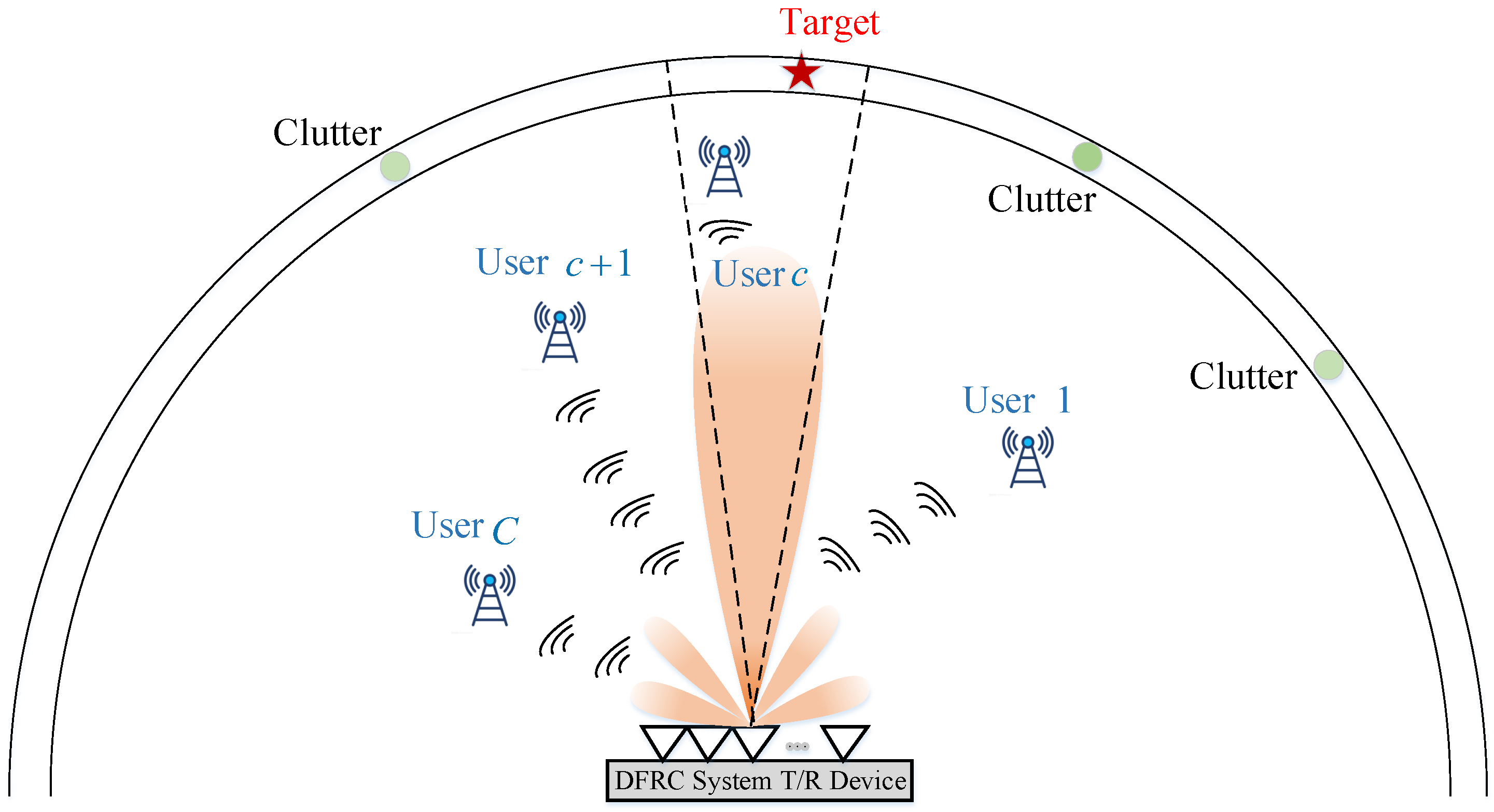
Figure 1. DFRC work scenario for detection and communication in signal-dependent clutter.
Remotesensing 15 03256 g001
Figure 2. An example of SPIA modulation.
Remotesensing 15 03256 g002
Figure 3. Information demodulation procedure.
Remotesensing 15 03256 g003
Figure 4. Beampattern performance under different parameters (a) SINR versus iteration number for η p 1 = 2 , κ = 0.0001 , 0.05 , (b) SINR versus iteration time (in seconds) η p 1 = 2 , κ = 0.0001 , 0.05 , (c) SINR versus iteration number for η p 1 = 2 , 5 , κ = 0.05 , (d) SINR versus iteration time (in seconds) η p 1 = 2 , 5 , κ = 0.05 , (e) beampattern versus angle for η p 1 = 2 , κ = 0.0001 , 0.05 , (f) beampattern versus angle for η p 1 = 2 , 5 , κ = 0.05 .
Remotesensing 15 03256 g004
Figure 5. Beampattern performance for Q 1 = 2 , 3 , 4 (a) the histogram of converged SINR values, (b) beampattern versus angle with the maximum converged SINR values.
Remotesensing 15 03256 g005
Figure 6. Communication performance (a) SER versus PNR for η p = 2 , 5 , κ = 0.0001 , 0.05 , Q 1 = 2 , 4 , (b) optimized frequency band energy for communication user assuming Q 1 = 4 , (c) optimized frequency band energy for communication user assuming Q 1 = 3 , (d) optimized frequency band energy for communication user assuming Q 1 = 2 .
Remotesensing 15 03256 g006
Figure 7. Beampattern performance for different application scenarios (a) beampattern versus angle (two users and three interfering sources), (b) beampattern versus angle (one user FL and four interfering sources).
Remotesensing 15 03256 g007
Figure 8. The comparison with sidelobe modulation in [9] (a) beampatterns versus angle using sidelobe modulation [9], (b) beampatterns versus angle using proposed SPIA modulation.
Remotesensing 15 03256 g008
Figure 9. The comparison with spatio-spectral modulation scheme in [12] (a) beampatterns versus angle, (b) data rate versus selected subband number, (c) optimized frequency band energy using proposed SPIA method (d) optimized frequency band energy using spatio-spectral modulation method [12].
Remotesensing 15 03256 g009
Table 1. The setting of simulational parameters.
Variable NameVariable Setting
Transmitting arrayUniform linear array
Antenna spacinghalf-wave
Antenna number N t = 8
Signal sample number M = 32
Parameters of mainlobe width constraints θ 0 = 15 , θ 1 = 5 , θ 2 = 25 , P L = 0.5 and δ = 0.05
Sidelobe region [ 90 , 5 ] [ 25 , 90 ]
Upper limit of antenna pattern ISL ε = 1.5
Upper limit of stopband energy η s = 5 × 10 5 × n s
Number of stopband n s
Exit condition value of IBE κ 2 = 10 5
Exit condition value of DIP κ 1 = 10 2
The location of communication user 70
The location of target θ 0 = 15
The power of target δ 0 2 = 20 dB
The location of two reference sources 30 and 60
The power of two reference sources 25 dB , 30 dB
Normalized available frequency subbands Ω 1 1 = ( 0.1 , 0.13 ) , Ω 2 1 = ( 0.2 , 0.23 ) , Ω 3 1 = ( 0.3 , 0.33 ) , Ω 4 1 = ( 0.4 , 0.43 ) , Ω 5 1 = ( 0.5 , 0.53 ) , Ω 6 1 = ( 0.6 , 0.63 ) , Ω 7 1 = ( 0.7 , 0.73 ) , Ω 8 1 = ( 0.8 , 0.83 ) , Ω 9 1 = ( 0.9 , 0.93 )
Table 2. The setting of simulational parameters.
NumberSPIA MethodNumberSpatio-Spectral Method [12]
1Two users positions 70 , 60 1Two users positions 70 , 60
2Lower bound of passband energies η p 1 = η p 2 = 2 2Lower bound of passband energies η p 1 = η p 2 = 2
3Upper bound of stopband energy η s = 5 × 10 5 × n s 3Upper bound of stopband energy η s = 2.5 × 10 5 × n s
4Two interference sources’ positions 30 , 50 4Without this parameter
5Power of two interference sources 25 dB , 30 dB 5Without this parameter
6Power of target δ 0 2 = 0 dB 6Without this parameter
7Ten frequency subbands are selected from the available frequency subbands using the spatio-spectral method [12] for information embedding7Frequency subbands for information embedding Ω 1 = ( 0.02 , 0.04 ) , Ω 2 = ( 0.07 , 0.09 ) , Ω 3 = ( 0.12 , 0.14 ) , Ω 4 = ( 0.17 , 0.19 ) , Ω 5 = ( 0.22 , 0.24 ) , Ω 6 = ( 0.27 , 0.29 ) , Ω 7 = ( 0.32 , 0.34 ) , Ω 8 = ( 0.37 , 0.39 ) , Ω 9 = ( 0.42 , 0.44 ) , Ω 10 = ( 0.47 , 0.49 ) , Ω 11 = ( 0.52 , 0.54 ) , Ω 12 = ( 0.57 , 0.59 ) , Ω 13 = ( 0.62 , 0.64 ) , Ω 14 = ( 0.67 , 0.69 ) , Ω 15 = ( 0.72 , 0.74 ) , Ω 16 = ( 0.77 , 0.79 ) , Ω 17 = ( 0.82 , 0.84 ) , Ω 18 = ( 0.87 , 0.89 ) , Ω 19 = ( 0.92 , 0.94 ) , Ω 20 = ( 0.97 , 0.99 )
Disclaimer/Publisher’s Note: The statements, opinions and data contained in all publications are solely those of the individual author(s) and contributor(s) and not of MDPI and/or the editor(s). MDPI and/or the editor(s) disclaim responsibility for any injury to people or property resulting from any ideas, methods, instructions or products referred to in the content.