Abstract
Recently, the problem of target detection in noisy environments for the Dual-Functional Radar Communication (DFRC) integration system has been a hot topic. In this paper, to suppress the noise and further enhance the target detection performance, a novel manifold Riemannian Improved Armijo Search Conjugate Gradient algorithm (RIASCG) framework has been proposed which jointly optimizes the integrated transmitting waveform and receiving filter. Therein, the reference waveform is first designed to achieve excellent pattern matching of radar beamforming. Furthermore, to ensure the quality of system information transmission, the energy of multi-user interference (MUI) of communication signals is incorporated as the constraint. Additionally, the typical similarity constraint is introduced to ensure the transmitting waveform with a good ambiguity function. Finally, simulation results demonstrate that the designed waveform not only enhances the system’s target detection performance in noisy environments but also achieves a relatively good multi-user communication ability when compared with other prevalent waveforms.
1. Introduction
In the past decades, with the rapid development of commercial wireless communication and remote sensing image processing [1,2,3], the demand for available frequency bands has also increased dramatically where most of the frequency resources are allocated to radar requirements and also limit the communication throughput. Therein, the integration of sensing and communication to improve spectrum utilization has become a research hotspot [4,5,6].
At present, the radar communication integration system can be divided into two categories according to whether the spectrum is shared: radar communication coexistence (RCC) [6] and dual functional radar communication (DFRC) [7]. For RCC, it means that radar and communication work independently on the same platform through some resource diversity, including frequency division multiplexing, power multiplexing and time division multiplexing [8]. Authors in [9] presented the power allocation and subcarrier selection scheme to minimize the transmission power while ensuring the presence of mutual information between radar and communication. Authors in [10] discussed the integration of radar communication by orthogonalizing radar and communication signals. Unlike RCC, DFRC integrates radar and communication functions through a single integrated waveform and allocates its power to a specific spatial area to detect targets while transmitting the user communication signals. Early research focused on the integrated waveform design where the digital information was embedded into the radar waveform by modifying the traditional radar waveform and controlling its sidelobe in the direction of the objective user [11,12]. Typically, when the communication user is in the mainlobe of the radar waveform, the communication rate would drop greatly, and the communication function would fail. Moreover, the communication symbols can also modulate the radar waveform to achieve coexistence for dual functions [13,14,15]. Authors in [16,17] tried to use the existing communication waveforms to achieve radar’s tasks. From the communication view, DFRC signals need high-quality communication performance, such as a high communication rate, which can be improved by minimizing multi-user interference (MUI).
Considering the scenarios involving multiple communication users and multiple radar sensing targets, the DFRC waveform has faced more challenges [18]. For communication, the signal-to-interference-plus-noise ratio (SINR) of each user should be considered. For radar, the SINR should also be considered. For DFRC systems, the performance of communication and sensing is coupled together, which means that any improvement of communication may deteriorate the radar performance, and vice versa. Therefore, in fact, when DFRC systems work in multi-user and multi-target scenarios, they inevitably face multiple performance tradeoffs between multi-users, multi-targets and also communication and perception. To solve this problem, authors in [19] designed the transmitting waveform by minimizing the joint least squares of weighted squared error and total MUI, where the weighting factor is used to balance two systems. Moreover, in this integration, most communication signals are modulated by multiple carriers, which will inevitably lead to a high peak average power ratio (PAPR) and incur distortion at the RF end. To improve the power efficiency of transmitters, PAPR constraints or constant modulus (CM) are widely used. Authors in [20] tried to jointly optimize the MUI and radar SINR by alternating the minimization and gradient projection frameworks. Authors in [21,22] designed the radar transmitting waveform under a given PAPR and similarity constraints. Note that radar waveforms as well as DFRC waveforms with constant modulus are also in need [23,24]. Authors in [25] designed a CM-integrated waveform by synthesizing different signals in the direction of communication and radar and also proposed an iterative optimization amplitude weighting method. No matter the PAPR/CM constraint or similarity constraint, these prior works would have to tackle the non-convex optimization problem with a heavy computation burden. How to design DFRC waveforms within the non-convex framework has been a hot topic. Furthermore, authors in [26] designed the CM DFRC waveform to minimize MUI and maximize the similarity between integrated signals and reference radar waveforms. Authors in [27] considered the joint design of the receiving filter and transmitting waveform with the maximum signal-to-noise ratio () and proposed a novel algorithm based on manifold ideas which give us lots of inspiration.
In this paper, to improve the detection performance of the integration system in noisy environments, the joint design of the system’s transmitting waveform and receiving filter has been proposed to enhance the output , which is based on the Riemannian Improved Armijo Search Conjugate Gradient algorithm (RIASCG) framework. This framework could transform the non-convex optimization problem into a novel convex one within Riemannian manifold space. Firstly, the MIMO radar waveform, with the constant modulus and similarity (CM&S) constraint as well as good directivity, was designed. Furthermore, the waveform with the minimum MUI was also considered. By using the manifold principle, the CM&S constraint was transformed into an unconstrained Riemannian space. Particularly in the Riemannian space, the final solution can be obtained through the iterative closed-form. Finally, we compare their performance with several existing ones.
The organization of this paper is as follows. The system model and problem formulation are presented in Section 2 and Section 3. The DFRC waveform design by the novel algorithm is proposed in Section 4. Section 5 presents the numerical results. Finally, conclusions are drawn in Section 6.
Notation: Lower-case letters and upper-case letters denote vectors and matrices, respectively. The symbols , and stand for the transpose, the conjugate transpose and the conjugate operators, respectively. The set of complex matrices and the set of -dimensional complex numbers vectors are denoted by and , respectively. The norm is denoted by the symbol , and the Frobenius norm is represented by the symbol . stands for the identity matrix of size . Finally, the notations and are denoted as the real and imaginary part of , represents the expectation operator, the symbol denotes the Kronecker product and the symbol represents the Hadamard product.
2. System Model
Cognitive radar adjusts its waveforms via artificial intelligence or machine learning as shown in Figure 1, which is regarded as a closed-loop feedback cycle. This adaptive system makes it more intelligent and offers higher robustness in waveform optimization compared with the traditional one. This paper focuses on the design of transmitting waveforms and receiving filters in DFRC systems where the integrated waveform is suitable for both target detection and information transmission. Namely, to achieve this, the optimization problem should satisfy the transmitted beampattern favorable for target detection while generating minimal MUI to multiple users in the downlink. The DFRC system needs to perform the following two tasks simultaneously: (i) target detection and (ii) communication with single-antenna users in the downlink.
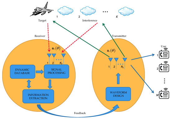
Figure 1.
MIMO DFRC system based on cognitive radar idea.
2.1. Communication Model
Assume that the channel between the bifunctional base-station and the communication user is flat Rayleigh fading and the channel characteristics remain unchanged for a certain period of time. The integrated MIMO radar-antenna system has transmitting antennas and receiving antennas, and the frame length of the dual-functional waveform is assumed to be . Suppose that there are communication users subjected to the interference from irrelevant signals when detecting the target. Specifically, the signals received by communication users can be represented as
where is the channel matrix. The transmission signal matrix is , where denotes the -th transmitted symbol vector, and is the white Gaussian noise matrix of the receiver.
Furthermore, as the integrated system would transmit a signal matrix to users, (1) can be rewritten as
where the second term in (2) represents the multi-user interference [19], and its energy can be expressed as with separable property . According to [20], the achievable sum-rate of the users can be defined as
where represents the of per-frame received by the -th user, i.e.,
where represents the -th code-unit for the -th user, is the power of the received noise, and the energy of the term of MUI can be expressed as . By minimizing the energy of MUI, the achievable rate of the system can be maximized, which is equivalent to minimizing .
2.2. Detection Model
This section primarily aims to synthesize waveforms to achieve beampattern matching while maximizing . The of the MIMO system is determined by the transmitted waveform and its covariance matrix . By optimizing the transmitting waveform vector, the quality of the radar-output signal can also be enhanced, which in turn improves the and anti-interference ability of radar and also improves the sensitivity and accuracy of target detection. Assuming that a point target exists in the direction , and independent interference sources are located at , then the received signals at the -th frame is formulated by
where are the amplitudes of target and interference sources, and denotes the receiver noise. The and are the propagation vector and steering vector for the direction where the transmit and receive arrays are assumed to be linear uniform ones with and . To simplify the expression, the vectors corresponding to in Equation (5) can be represented as
where , , , .
To improve the detection performance, it is required to process the received signal. Regarding the receiving filter , the resulting output can be expressed as
In Equation (7), the first term represents the desired signal, the second term represents the interference signal, and the third term represents the noise. Thus, the of the filter output can be expressed as
where represents the complex amplitude of . Generally, in a Gaussian noise environment, the larger the , the better the detection performance would be. Equation (8) can be transformed into a convex problem for a fixed .
where . Furthermore, to accurately obtain some information of target or interference in the environment, waveforms in all directions should be equipped with some low sidelobes so as to reduce mutual interference. The beampattern power located at can be expressed as
Considering that each array has the same emission energy, i.e., unitary power, the covariance matrix can be designed as
where represents the -th element of covariance matrix . denotes an expected transmit beampattern where is a fine grid covering the points of interest. Assuming that there are expected target locations, the objective is to detect the target at locations , which can be confirmed by calculating the Capon spatial spectrum or generalized likelihood ratio test (GLRT) [28]. Here, the dominant peak position has been calculated by the GLRT pseudo-spectrum so as to form the desired beampattern , and is the resulting estimate of , i.e.,
where is the beamwidth selected by each target.
Based on the aforementioned discussions, it is necessary to design a matrix that minimizes the least squares error between the transmitted beampattern and the expected beampattern , while also minimizing the cross-correlation terms from different backscattered signals. Consequently, the corresponding problem could be expressed as
where represents the weight factor of the -th source, represents the weight factor of the cross-correlation term, and is a scaling factor that needs to be optimized.
Moreover, some appropriate constraints are further imposed on the covariance matrix , which also considers the need of the low cross-correlation beampattern. The designed must be positive semidefinite, and all diagonal elements of must be equal to the uniform antenna power while satisfying the uniform basic-power constraint. The covariance optimization problem can be formulated as
To solve the optimization problem of variables , the convex optimization toolbox CVX can be employed [29]. Note that when designing MIMO radar systems with low cross-correlation beampatterns, it is crucial to make a balance between detection and communication performance. It is necessary to define the optimization objectives and constraints based on the specific application requirements. This ensures that the design effectively meets the desired performance criteria.
3. Optimization Modeling of Radar and Communication Integrated System
In this section, the optimization objective is to maximize while considering the signal-dependent interference. The design of the covariance matrix and transmitting waveform of MIMO radar will be addressed simultaneously. In practical radar applications, to improve the detection performance while maintaining the ability of multi-user communication, good ambiguity function and range resolution characteristics, it is necessary to introduce similarity constraints, such as
where is the reference waveform and is the similarity coefficient. To enhance detection performance and facilitate multi-user communication, the permissible range of is usually set as , where . It should be noted that the communication performance may be severely degraded under the above constraints. Once the output result is obtained as the integrated referenced waveform , then it is equivalent to add the communication information into the integrated signal. Therefore, the optimization problem for the design of directional beamforming can be formulated as
According to [19], the problem described in (16) can be characterized as an Orthogonal Procrustes problem (OPP) with a closed-form solution , where represents the Cholesky decomposition or other valid square-root decomposition, while represents the singular value decomposition (SVD). Consequently, the benchmark radar waveform is uncorrelated with the power of the desired constellation .
Next, a compromise constraint, i.e., , is proposed, where defines the maximum permissible level for the communication performance metric and radar waveform similarity error. By taking the limited transmission energy into account, the optimization problem can be formulated as
where denote the weight factor, and represents the total power of all antennas per symbol. The constraint conditions can be transformed into the following composite form [19], i.e.,
Denoting and , Equation (18) can be rewritten and extended to
Further defining and , Equation (19) can be rewritten as
where is a Hermitian matrix, Equation (20) can be written in the form of a Lagrange multiplier with respect to the total power as follows
where is the dual variable of the equality constraint. Defining and as the optimal point and the dual optimal point with zero duality gap, according to the trust-region subproblem (TRS) optimality conditions [30], the following conclusions show
where the notation refers to the Moore–Penrose pseudoinverse of the matrix. Furthermore, the matrix can be decomposed into where denotes the minimum eigenvalue of . It can be further proved that formula (22) has a unique solution, i.e.,
From deduction of (23), it is noted that when , the function is strictly decreasing and convex. Therefore, the golden-section search method can be employed to determine the optimal solution for .
4. Waveform Optimization Algorithm
In this section, a novel RIASCG algorithm is proposed to optimize the objective function. The Riemann gradient of function is defined as , which can be obtained by projecting the gradient on the Euclidean space. Here, represents the Euclidean gradient of , and the contraction operator maps the vector on the tangent space at the vicinity of manifold . The next iteration point is considered when the objective value satisfies the descent condition. In each descent process, a more accurate step size needs to be selected to ensure faster convergence. To achieve this, an improved Riemannian manifold conjugate gradient algorithm based on the Armijo back-tracking line-search idea is proposed, offering several advantages over the first-order conjugate gradient algorithm [27]:
- (1)
- Faster convergence speed: The second-order conjugate gradient algorithm, utilizing second-order derivative information, could more accurately determine the search direction and step size compared with the first-order conjugate gradient one, resulting in better results in the same number of iterations.
- (2)
- More effective optimization for high-dimensional data: The first-order conjugate gradient algorithm may have a slow convergence speed when optimizing high-dimensional data, while the second-order conjugate gradient algorithm can better overcome this problem.
- (3)
- Stronger numerical stability: The second-order conjugate gradient algorithm can better avoid numerical instability, which is particularly prominent in optimizing high-dimensional data.
- (4)
- Fewer iterations: Due to faster convergence, the second-order conjugate gradient algorithm typically requires fewer iterations to achieve the same optimization effect, which is particularly important for optimizing large-scale data.
Suppose that the above constraints can be denoted as . For any , its projection operator of the sequence can be expressed as
Once the input is given, it is possible to apply a universal compression function to effectively address common constraints, i.e.,
The closed-form solution of in Equation (17) can be derived, i.e.,
As a result, a subproblem of the optimization problem has been obtained, i.e.,
The subproblem can be further expressed as
The Euclidean gradient of the smooth extension can be denoted as , i.e.,
The steps of manifold RIASCG for DFRC waveform design can be summarized in Algorithm 1.
| Algorithm 1: The Manifold RIASCG for DFRC Waveform Design. |
| Input: weight factor . Output: . |
| While do |
| 1. Compute . 2. Compute the eigenvalue decomposition of , set the searching interval as [,], where is a searching upper-bound. 3. Find the optimal solution to (22) using golden-section search. 4. Compute . 5. Once the global minimizer is obtained, given its separability property, it can be employed as the reference waveform for the similarity constraint, denoted as . |
| 6. Compute according to (29). |
| 7. Compute according to (24). |
| 8. Compute the improved Armijo back-tracking line-search parameter , is the smallest non-negative integer satisfying |
| 9. Perform the projection step . 10. Obtain according to (25). 11. . |
| End while Compute according to (26). |
5. Numerical Result
To evaluate the performance of the designed waveforms, we first formulated the simulation scenarios. A uniform linear array configuration is assumed for both the transmitting and receiving arrays. Units in these arrays have an element spacing of half a wavelength. The number of transmitting antennas is , the number of receiving antennas is , and the target echo power is . Additionally, the interference power is set to , the noise power is and the code-length of the waveform is , while and are drawn from and , respectively. For convenience, and assume that each entry of the channel matrix is modeled as flat fading one and also is independently and identically distributed with a standard complex Gaussian distribution . The constellation selected for the communication users is the unit-power QPSK alphabet, and the threshold value of is set as .
By employing Equation (14), the objective is to construct the covariance matrix for problem (16), and then its performance would be compared with the omni-directional waveform. Assume that there are four users, and the direction of arrival (DoA) information for targets with unit complex amplitude is approximately , which can be obtained by the Capon or GLRT method. Three symmetrical beampatterns of interest are denoted as , with a beampattern width of . Next, the performance of the omni-directional and directional beampattern would be discussed, and a radar-communication compromise waveform would be designed to achieve some flexible trade-off between radar and communication for practical needs. Considering the trade-off design for radar communication, the Pareto weight factor is introduced, and ‘Omni’ and ‘Directional’ are denoted as the omnidirectional and directional beam-patterns. Further, the waveforms with strict equality constraints are denoted as ‘Strict’, while the trade-off designs are denoted as ‘Tradeoff’. In Figure 2, it is evident that the proposed method exhibits significantly lower sidelobe levels compared to the method of [19].
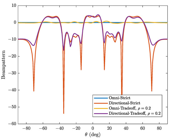
Figure 2.
Comparison of radar beampattern corresponding to different cases.
Moreover, to further assess the robustness of different algorithms, the proposed RIASCG would be compared with RCG [31], MM [32], MM-SQUAREM [33] and RCG-Armijo algorithms. To enhance the comparability, two additional constraints are also incorporated: the constant modulus constraint [34] and the e-uncertainty constant modulus constraint [35]. As shown in Figure 3, in comparison to the first-order RCG-Armijo algorithm, the second-order conjugate RIASCG algorithm used in this paper demonstrates faster convergence. The first-order conjugate gradient algorithm needs some precise line searching, which could increase computational costs and lead to some direction inconsistency in certain cases. Particularly in ill-conditioned problems, this algorithm might encounter direction loss within iterations and fail to converge to the minimum value. In such scenarios, the second-order conjugate gradient algorithm appears to be more advantageous than the first-order one, as it utilizes more information to determine the search direction and reduces the direction inconsistency. The RIASCG algorithm has demonstrated fewer iterations and a faster convergence rate compared with other algorithms.
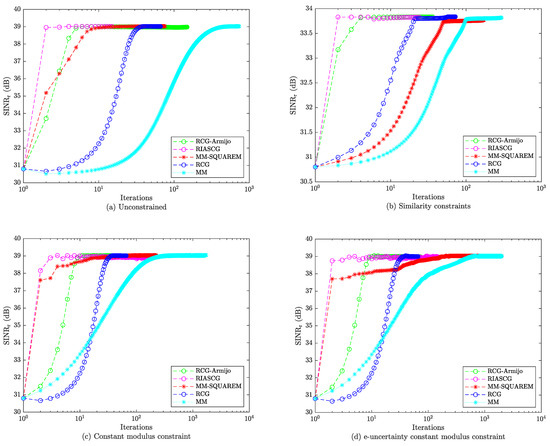
Figure 3.
Comparison of convergence rates under different constraints. (a) Unconstrained; (b) Similarity constraints; (c) Constant modulus constraint; (d) e-uncertainty constant modulus constraint.
To evaluate the scalability and robustness of algorithms, the computation runtime comparisons were also conducted for different in Table 1 considering the CM&S constraint. Obviously, the practicality and scalability of RIASCG has effectively demonstrated that the comparative runtime performance has outperformed other prior works, such as RCG, RCG-Armijo, MM and MM-SQUAREM, especially for larger . These comparisons could underscore the effectiveness and applicability of RIASCG.

Table 1.
Runtime comparisons of different methods under CM&S constraint.
Next, the effect of the similarity constraint has been discussed. As shown in Figure 4, when the similarity coefficient between two users is lower, it indicates a lower similarity between their signals, which can result in a greater degree of interference between them. When multiple users transmit signals simultaneously, the interference will affect the quality of the received signal and also result in a lower . In Figure 5, waveforms optimized by RIASCG algorithm as decreasing have shown different shapes of ambiguity function. The similarity between the designed waveform and the reference waveform would be gradually increased, which would result in a better-formed ambiguity function. However, this also leads to a reduction in the degrees of freedom for waveform design.
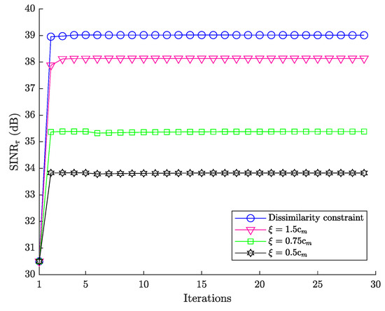
Figure 4.
vs. iteration number for different .
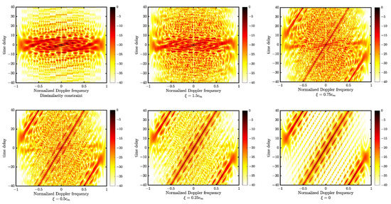
Figure 5.
Ambiguity functions of the presented waveforms as decreasing.
Furthermore, given a specified radar beampattern, the design of dual-function waveforms is further analyzed. As demonstrated in Figure 6, we define the transmit as , and then examine the relationship between the transmit of the communication signal and the average achievable sum-rate. Here, represents the stopping criterion for the golden-section search iteration. As the transmit increases, the effect of the signal synthesis error on the average achievable sum-rate increases. Therefore, the sum-rate of the synthesized signal is slightly lower than that of a single communication signal.
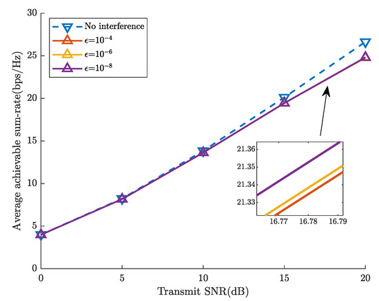
Figure 6.
comparison of different stop conditions for golden-section search iterations.
Moreover, in Figure 7, the relationship between the average achievable rate per-user vs. the detection probability is illustrated when the receive has and the false-alarm probability has . With an increase in the number of users, the detection probability would be decreased for a fixed average achievable rate per-user, which suggests that the increasing degrees of freedom could further minimize MUI energy. In Figure 8, the relationship between the average achievable rate per-user vs. the number of iterations has been demonstrated. Once the number of communication users increases, the feasible solution space decreases, which leads to a decline in the average achievable rate.
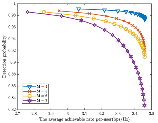
Figure 7.
The average achievable rate per-user vs. radar detection probability.
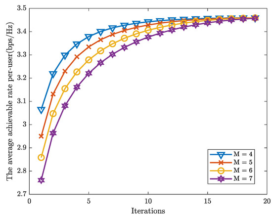
Figure 8.
The average achievable rate per-user vs. number of iterations.
6. Conclusions
In this paper, we aimed to design an integrated waveform for DFRC using an RIASCG framework, which offers a flexible trade-off between radar and communication performance. To accomplish this, the manifold principle was leveraged to transform the constrained CM&S problem into unconstrained Riemann spaces, ensuring radar beampattern constraints and their trade-offs. Simulations have demonstrated the convergence performance and superiority of RIASCG when compared with other existing algorithms. Moreover, by adjusting the similarity coefficient, the designed waveform exhibited desirable properties in terms of the ambiguity function. As this paper demonstrated, we mainly focused on presenting a novel optimizing idea to tackle the joint optimization of integrated transmitting waveforms and receiving filters, which ignores the relative motion or Doppler shift. Next, in our future research, we will investigate the influence of relative motion and the Doppler shift and try to assess the robustness and adaptability of the proposed techniques in realistic scenarios. Additionally, we will also investigate the impact of varying channel conditions and different fading models, such as frequency-selective fading or multipath fading.
Author Contributions
Conceptualization, Y.Z. and X.F.; data curation, Z.Z. (Zhongqing Zhao) and F.T.; formal analysis, X.F. and P.S.; funding acquisition, X.F. and Y.Z.; investigation, Y.Z., X.F. and Z.Z. (Zhanfeng Zhao); methodology, X.F., Z.Z. (Zhanfeng Zhao) and P.S.; project administration, Y.Z., X.F. and Z.Z. (Zhongqing Zhao); resources, Z.Z. (Zhanfeng Zhao) and P.S.; supervision, X.F.; validation, Y.Z. and F.T.; writing—original draft, X.F. and Z.Z. (Zhongqing Zhao); writing—review and editing, X.F. and F.T. All authors have read and agreed to the published version of the manuscript.
Funding
This research was supported in part by the major scientific and technological innovation projects of Shandong Province of China (Grant No. 2021ZLGX05 and 2022ZLGX04).
Data Availability Statement
Not applicable.
Conflicts of Interest
The authors declare no conflict of interest.
References
- Liu, R.; Li, M.; Liu, Y.; Wu, Q.; Liu, Q. Joint Transmit Waveform and Passive Beamforming Design for RIS-Aided DFRC Systems. IEEE J. Sel. Top. Signal Process. 2022, 16, 995–1010. [Google Scholar] [CrossRef]
- Qian, X.; Zeng, Y.; Wang, W.; Zhang, Q. Co-Saliency Detection Guided by Group Weakly Supervised Learning. IEEE Trans. Multimed. 2023, 25, 1810–1818. [Google Scholar] [CrossRef]
- Lin, S.; Zhang, M.; Cheng, X.; Wang, L.; Xu, M.; Wang, H. Hyperspectral Anomaly Detection via Dual Dictionaries Construction Guided by Two-Stage Complementary Decision. Remote Sens. 2022, 14, 1784. [Google Scholar] [CrossRef]
- Yuan, W.; Wei, Z.; Li, S.; Yuan, J.; Ng, D.W.K. Integrated Sensing and Communication-Assisted Orthogonal Time Frequency Space Transmission for Vehicular Networks. IEEE J. Sel. Top. Signal Process. 2021, 15, 1515–1528. [Google Scholar] [CrossRef]
- Liu, R.; Li, M.; Liu, Q.; Swindlehurst, A.L. Joint Waveform and Filter Designs for STAP-SLP-Based MIMO-DFRC Systems. IEEE J. Sel. Areas Commun. 2022, 40, 1918–1931. [Google Scholar] [CrossRef]
- Labib, M.; Marojevic, V.; Martone, A.F.; Reed, J.H.; Zaghloui, A.I. Coexistence between Communications and Radar Systems: A Survey. URSI Radio Sci. Bull. 2017, 2017, 74–82. [Google Scholar] [CrossRef]
- Ma, D.; Shlezinger, N.; Huang, T.; Liu, Y.; Eldar, Y.C. Joint Radar-Communication Strategies for Autonomous Vehicles: Combining Two Key Automotive Technologies. IEEE Signal Process. Mag. 2020, 37, 85–97. [Google Scholar] [CrossRef]
- Chen, Y.; Gu, X. Time Allocation for Integrated Bi-Static Radar and Communication Systems. IEEE Commun. Lett. 2021, 25, 1033–1036. [Google Scholar] [CrossRef]
- Tian, T.; Li, G.; Zhou, T. Power Distribution for an OFDM-Based Dual-Function Radar-Communication Sensor. IEEE Sens. Lett. 2020, 4, 1–4. [Google Scholar] [CrossRef]
- Yu, X.; Yao, X.; Yang, J.; Zhang, L.; Kong, L.; Cui, G. Integrated Waveform Design for MIMO Radar and Communication via Spatio-Spectral Modulation. IEEE Trans. Signal Process. 2022, 70, 2293–2305. [Google Scholar] [CrossRef]
- Hassanien, A.; Amin, M.G.; Zhang, Y.D.; Ahmad, F. Dual-Function Radar-Communications: Information Embedding Using Sidelobe Control and Waveform Diversity. IEEE Trans. Signal Process. 2016, 64, 2168–2181. [Google Scholar] [CrossRef]
- Cheng, Z.; Wu, L.; Wang, B.; Shankar, M.R.B.; Ottersten, B. Double-Phase-Shifter Based Hybrid Beamforming for MmWave DFRC in the Presence of Extended Target and Clutters. IEEE Trans. Wirel. Commun. 2023, 22, 3671–3686. [Google Scholar] [CrossRef]
- Ahmed, A.; Zhang, Y.D.; Gu, Y. Dual-Function Radar-Communications Using QAM-Based Sidelobe Modulation. Digit. Signal Process. 2018, 82, 166–174. [Google Scholar] [CrossRef]
- Huang, T.; Xu, X.; Liu, Y.; Shlezinger, N.; Eldar, Y.C. A Dual-Function Radar Communication System Using Index Modulation. In Proceedings of the 2019 IEEE 20th International Workshop on Signal Processing Advances in Wireless Communications (SPAWC), Cannes, France, 2–5 July 2019; pp. 1–5. [Google Scholar]
- Yang, J.; Cui, G.; Yu, X.; Kong, L. Dual-Use Signal Design for Radar and Communication via Ambiguity Function Sidelobe Control. IEEE Trans. Veh. Technol. 2020, 69, 9781–9794. [Google Scholar] [CrossRef]
- Sen, S. PAPR-Constrained Pareto-Optimal Waveform Design for OFDM-STAP Radar. IEEE Trans. Geosci. Remote Sens. 2014, 52, 3658–3669. [Google Scholar] [CrossRef]
- Zhou, S.; Liang, X.; Yu, Y.; Liu, H. Joint Radar-Communications Co-Use Waveform Design Using Optimized Phase Perturbation. IEEE Trans. Aerosp. Electron. Syst. 2019, 55, 1227–1240. [Google Scholar] [CrossRef]
- Hassanien, A.; Amin, M.G.; Aboutanios, E.; Himed, B. Dual-Function Radar Communication Systems: A Solution to the Spectrum Congestion Problem. IEEE Signal Process. Mag. 2019, 36, 115–126. [Google Scholar] [CrossRef]
- Liu, F.; Zhou, L.; Masouros, C.; Li, A.; Luo, W.; Petropulu, A. Toward Dual-Functional Radar-Communication Systems: Optimal Waveform Design. IEEE Trans. Signal Process. 2018, 66, 4264–4279. [Google Scholar] [CrossRef]
- Tsinos, C.G.; Arora, A.; Chatzinotas, S.; Ottersten, B. Joint Transmit Waveform and Receive Filter Design for Dual-Function Radar-Communication Systems. IEEE J. Sel. Top. Signal Process. 2021, 15, 1378–1392. [Google Scholar] [CrossRef]
- De Maio, A.; Huang, Y.; Piezzo, M.; Zhang, S.; Farina, A. Design of Optimized Radar Codes With a Peak to Average Power Ratio Constraint. IEEE Trans. Signal Process. 2011, 59, 2683–2697. [Google Scholar] [CrossRef]
- Cheng, Z.; He, Z.; Liao, B.; Fang, M. MIMO Radar Waveform Design With PAPR and Similarity Constraints. IEEE Trans. Signal Process. 2018, 66, 968–981. [Google Scholar] [CrossRef]
- Cui, G.; Li, H.; Rangaswamy, M. MIMO Radar Waveform Design With Constant Modulus and Similarity Constraints. IEEE Trans. Signal Process. 2014, 62, 343–353. [Google Scholar] [CrossRef]
- BouDaher, E.; Hassanien, A.; Aboutanios, E.; Amin, M.G. Towards a Dual-Function MIMO Radar-Communication System. In Proceedings of the 2016 IEEE Radar Conference (RadarConf), Philadelphia, PA, USA, 2–6 May 2016; pp. 1–6. [Google Scholar]
- Jiang, M.; Liao, G.; Yang, Z.; Liu, Y.; Chen, Y. Integrated Radar and Communication Waveform Design Based on a Shared Array. Signal Process. 2021, 182, 107956. [Google Scholar] [CrossRef]
- Shi, S.; Wang, Z.; He, Z.; Cheng, Z. Constrained Waveform Design for Dual-Functional MIMO Radar-Communication System. Signal Process. 2020, 171, 107530. [Google Scholar] [CrossRef]
- Liu, F.; Masouros, C.; Li, A.; Sun, H.; Hanzo, L. MU-MIMO Communications With MIMO Radar: From Co-Existence to Joint Transmission. IEEE Trans. Wirel. Commun. 2018, 17, 2755–2770. [Google Scholar] [CrossRef]
- Bose, A.; Khobahi, S.; Soltanalian, M. Efficient Waveform Covariance Matrix Design and Antenna Selection for MIMO Radar. Signal Process. 2021, 183, 107985. [Google Scholar] [CrossRef]
- Grant, M.; SP, B. CVX: MATLAB Software for Disciplined Convex Programming. 2014. Available online: http://cvxr.com/cvx (accessed on 19 March 2023).
- Rendl, F.; Wolkowicz, H. A Semidefinite Framework for Trust Region Subproblems with Applications to Large Scale Minimization. Math. Program. 1997, 77, 273–299. [Google Scholar] [CrossRef]
- Alhujaili, K.; Monga, V.; Rangaswamy, M. Transmit MIMO Radar Beampattern Design via Optimization on the Complex Circle Manifold. IEEE Trans. Signal Process. 2019, 67, 3561–3575. [Google Scholar] [CrossRef]
- Hunter, D.R.; Lange, K. A Tutorial on MM Algorithms. Am. Stat. 2004, 58, 30–37. [Google Scholar] [CrossRef]
- Song, J.; Babu, P.; Palomar, D. Sequence Design to Minimize the Weighted Integrated and Peak Sidelobe Levels. IEEE Trans. Signal Process. 2015, 64, 2051–2064. [Google Scholar] [CrossRef]
- He, H.; Li, J.; Stoica, P. Waveform Design for Active Sensing Systems: A Computational Approach; Cambridge University Press: Cambridge, UK; New York, NY, USA, 2012. [Google Scholar]
- Zhao, L.; Song, J.; Babu, P.; Palomar, D.P. A Unified Framework for Low Autocorrelation Sequence Design via Majorization–Minimization. IEEE Trans. Signal Process. 2017, 65, 438–453. [Google Scholar] [CrossRef]


Disclaimer/Publisher’s Note: The statements, opinions and data contained in all publications are solely those of the individual author(s) and contributor(s) and not of MDPI and/or the editor(s). MDPI and/or the editor(s) disclaim responsibility for any injury to people or property resulting from any ideas, methods, instructions or products referred to in the content. |
© 2023 by the authors. Licensee MDPI, Basel, Switzerland. This article is an open access article distributed under the terms and conditions of the Creative Commons Attribution (CC BY) license (https://creativecommons.org/licenses/by/4.0/).