1. Introduction
Radar (Radio Detection and Ranging) actively emits electromagnetic waves and utilizes their reflections to acquire information about the target, including its distance, azimuth, and velocity. Modern radar performs various essential functions, such as detection, positioning, recognition, tracking, and imaging, playing significant roles in both military and civilian applications. In aviation, airborne radar is widely used, providing reliable situational awareness, navigation, and monitoring capabilities during adverse weather conditions and nighttime flights. Advancements in technology have led to airborne radar systems that offer higher resolution, increased data accuracy, and expanded monitoring ranges.
When operating in the down-looking mode, airborne radar must consider the presence of ground clutter. The Doppler frequency of ground clutter varies based on the angle between the radar and the ground, causing significant range and Doppler ambiguities. Pulse Doppler radar is commonly employed for ground detection to distinguish targets from strong clutter echoes. The medium-pulse repetition frequency (MPRF) waveform is widely used in pulse Doppler radar to accurately measure target range and velocity in the presence of strong clutter. The adoption of multiple pulse repetition frequencies (Multi-PRF) in MPRF radar is necessary to resolve range and Doppler frequency ambiguities effectively. For optimal PRF selection, minimizing blind zones in terms of distance and velocity while ensuring full resolution of real distance and Doppler frequency ambiguities is crucial.
Hovanessian S.A. [
1] was the first to conduct an analysis of the MPRF, and perform a distance and Doppler ambiguity analysis of MPRF waveforms. The clutter distribution in the down-looking mode of airborne radar was also explored, and the clutter’s ambiguous characteristics on the Range Doppler (RD) map were analyzed. Diani et al. [
2] introduced a ground clutter model for the down-looking mode of radar, and to reduce the computational complexity of traditional clutter calculation methods, Liu Tao et al. [
3] derived the expression of the boundary of range-Doppler cells in spherical coordinates, describing the process of calculating ground clutter range-Doppler spectra only in spherical coordinates. Zhang Chun-cheng et al. [
4] presented a ground clutter echo model under high PRF, and discussed the clutter-induced distance ambiguity in the RD results. Agarwal et al. [
5] introduced a blind zone model for distance-velocity measurement caused by ground clutter in airborne MPRF radar. Since a set of fixed PRFs has fixed ambiguous characteristics, multiple sets of PRF signals can be used in conjunction with the Chinese remainder theorem to perform de-ambiguity processing of targets after ambiguity [
6,
7,
8]. This method of combining multiple sets of PRFs is also widely used in practical applications today. Narasimhan et al. [
9] proposed a target parameter extraction method under MPRF target distance and velocity ambiguity, using the Chinese remainder theorem combined with clustering methods to solve the problem of target cross-distance units in different PRF groups. Tien et al. [
10] used interleaved transmission of different PRF signals and can perform coherent processing, effectively expanding the Doppler unambiguous measurement capability.
In recent years, due to its superior anti-jamming capability and the ability to optimize the range-Doppler two-dimensional ambiguity, the use of random PRF has been increasingly researched and applied in addition to the traditional fixed PRF approach [
10,
11,
12,
13,
14,
15]. Duan et al. [
16] proposed a radar operating mode that uses pulse trains with time intervals to eliminate range and Doppler ambiguity by appropriately setting the pulse interval difference. Long et al. [
17] pointed out the beneficial electronic countermeasures brought by the use of random frequency and pulse repetition interval agile signals to radar systems. By analyzing the ambiguity function, they determined the expected value and variance of the ambiguity function of signals in multiple ambiguity ranges under arbitrary agile probability density function (PDF) conditions. Pan et al. [
18] proposed a coherent integration method for random pulse repetition interval and staggered pulse width, which has strong anti-jamming capability. They used the radon-non-uniform fast Fourier transform (Radon-NUFFT) method to solve the problems of non-uniform sampling and irregular range-Doppler coupling caused by random pulse repetition interval (PRI) and staggered pulse width (PW). Ma et al. [
19] proposed an improved sinc interpolation theory-based approach for dynamic target imaging with random pulse interval signals. They reconstructed non-uniformly sampled signals into a uniform grid in the distance-frequency domain, then constructed a matching filtering function related to the target’s linear frequency modulation parameters to eliminate residual coupling between distance and azimuth, and obtained good imaging results after target motion compensation. Fan et al. designed the transmission and reception of non-uniform pulse interval airborne radar. By designing the PRI of transmission and the phase-coefficient of the received pulses, the clutter in the target’s environment can be suppressed, significantly improving the detection performance of targets that are submerged in clutter. Kong et al. [
20] addressed the issue of ambiguous clutter in airborne radar by designing random pulse intervals. Through non-uniform phase-coherent processing, they can eliminate the ambiguous clutter spectrum and analyze the maximum unambiguous range and maximum unambiguous Doppler. In addition to random PRF, PRF jitter [
21,
22], adaptive PRF selection [
23,
24], and other designs can also be employed to enhance the radar’s de-ambiguity capability and target detection performance.
For the detection of targets under radar down-looking conditions, the general approach is to suppress clutter and then use constant false-alarm rate (CFAR) detection to detect the targets after filtering out the ground clutter. Typical methods for detecting moving targets with single-channel radar include moving target indication (MTI) and moving target detection (MTD). However, due to the Doppler spectrum broadening of airborne radar, the MTI filter spectrum also needs to be large, which may result in a loss of target detection performance in the clutter spectrum vicinity. Under airborne radar conditions, due to the complex clutter environment, the MTI filter parameters must be adaptively adjusted according to the actual clutter changes to effectively attenuate the clutter. In addition, to detect low-speed targets on the ground, such as trucks and tanks, the MTI filter must have a wide enough passband and steep transition band. Huang Yong et al. [
25] proposed a flexible filter design method that can not only adaptively adjust the filter parameters according to the actual clutter conditions, but also prevent the attenuation of slow-moving targets. A new method based on “filter-then-adapt” was proposed in [
26] for single-channel airborne radar. The new method can weaken non-uniformity and adaptively suppress clutter. Wu Renbiao et al. [
27] proposed an adaptive clutter suppression method based on echo power. The center frequency and bandwidth of the clutter spectrum were effectively estimated using prior information and polar coordinate centroid method. The echo power in each range bin was used to design an adaptive notch filter with dual threshold control.
The detection capability of slow-moving ground targets is a necessary condition for the effective engagement of ground targets by combat aircraft [
28,
29,
30]. Space–time adaptive processing (STAP) is an important method for improving the detection performance of airborne radars, which has received considerable attention from researchers in recent years [
31,
32]. When an airborne radar operates in a down-looking mode, the total clutter echoes from various directions are superimposed and cause Doppler broadening, which makes the detection of low-Doppler targets difficult. Ground moving target indication (GMTI) aims to detect slowly moving ground targets in the presence of strong clutter echoes. Research on GMTI and clutter suppression for radar platforms began in the 1960s, and typical platform motion compensation methods are displaced phase center antenna (DPCA) and STAP. However, both DPCA and STAP require at least two receiving channels. The application of STAP to side-looking airborne radars with relatively stationary ground clutter has achieved good performance, but due to severe distance dependence, especially for non-side-looking airborne radars, the performance is poor. When the PRF is high enough to cause range ambiguity, the clutter Doppler at close ranges changes rapidly for non-side-looking airborne radars, while the clutter Doppler at far ranges changes slowly, and clutter at different ambiguous ranges does not overlap. Meng Xiangdong et al. [
33] proposed a subarray synthesis algorithm with elevation pre-filtering. Through this technology, ambiguous short-range clutter is eliminated before STAP, and the range dependence of clutter is alleviated, greatly improving the performance of STAP. Wang et al. [
34] proposed using STAP combined with multiple interleaved mid-pulse repetition frequencies for processing. The update of the radar system can also provide new capabilities for clutter suppression and target detection of airborne radars. Wang Yuzhuo et al. [
35] proposed a frequency diverse array (FDA) MIMO radar range ambiguity clutter suppression method based on transmit beam main lobe correction. This method first uses designed transmit pulse weighting to compensate for the initial phase accumulated by the pulse frequency increment, thereby solving the problem of inconsistent high-gain illumination angles of the main lobe of the synthesized MIMO equivalent transmit beam pattern.
In this paper, we conduct a study on the detection of airborne radar down-looking targets based on orthogonal signals combined with PRF staggered transmission. We employ multiple sets of PRF signal groups with orthogonal waveforms for target detection and range-Doppler ambiguity resolution. Additionally, we apply coherent processing to the results of multiple PRF signal groups, using the transmission intervals, to enhance the SNR of the targets, thereby facilitating the detection of low SNR targets. The major contributions of this paper are as follows:
By using orthogonal DFC signals, targets under different PRFs can be separated, avoiding false target interference in different PRF signal groups;
Staggered transmitting multiple sets of PRF signals and utilizing the first pulse emission time of each set of PRF to perform coherent fusion on the RD results can significantly improve the target’s SNR, increase the coherent processing time, and improve the Doppler resolution of the target.
This paper is organized according to the following framework. The second part of this paper mainly constructs the clutter model, down-looking detection model, and PRF staggered transmission model of airborne radar and introduces the ambiguous situation of the RD map of target and clutter under different PRFs. In the third part of the paper, the signal processing flow and radar blind zone optimization are mainly discussed and designed. The fourth part performs performance analysis on the algorithm’s target detection and parameter estimation processes to validate the effectiveness of the algorithm presented in this paper.
2. Airborne Radar Clutter Model and Signal Model
2.1. Airborne Radar Clutter Model
The main problem in airborne radar air-to-air target detection is the range-Doppler ambiguity. The primary factor influencing target range-Doppler ambiguity is the PRF. Pulse radar typically uses a fixed PRF, categorized as low pulse repetition frequency (LPRF), medium pulse repetition frequency (MPRF), or high pulse repetition frequency (HPRF).
When an airborne radar operates in down-looking mode, ground clutter within a resolution cell consists of numerous randomly scattered objects with random amplitude and phase. Therefore, it is common to describe the amplitude characteristics of clutter using probability density functions, such as Gaussian, Rayleigh, and Rice distributions.
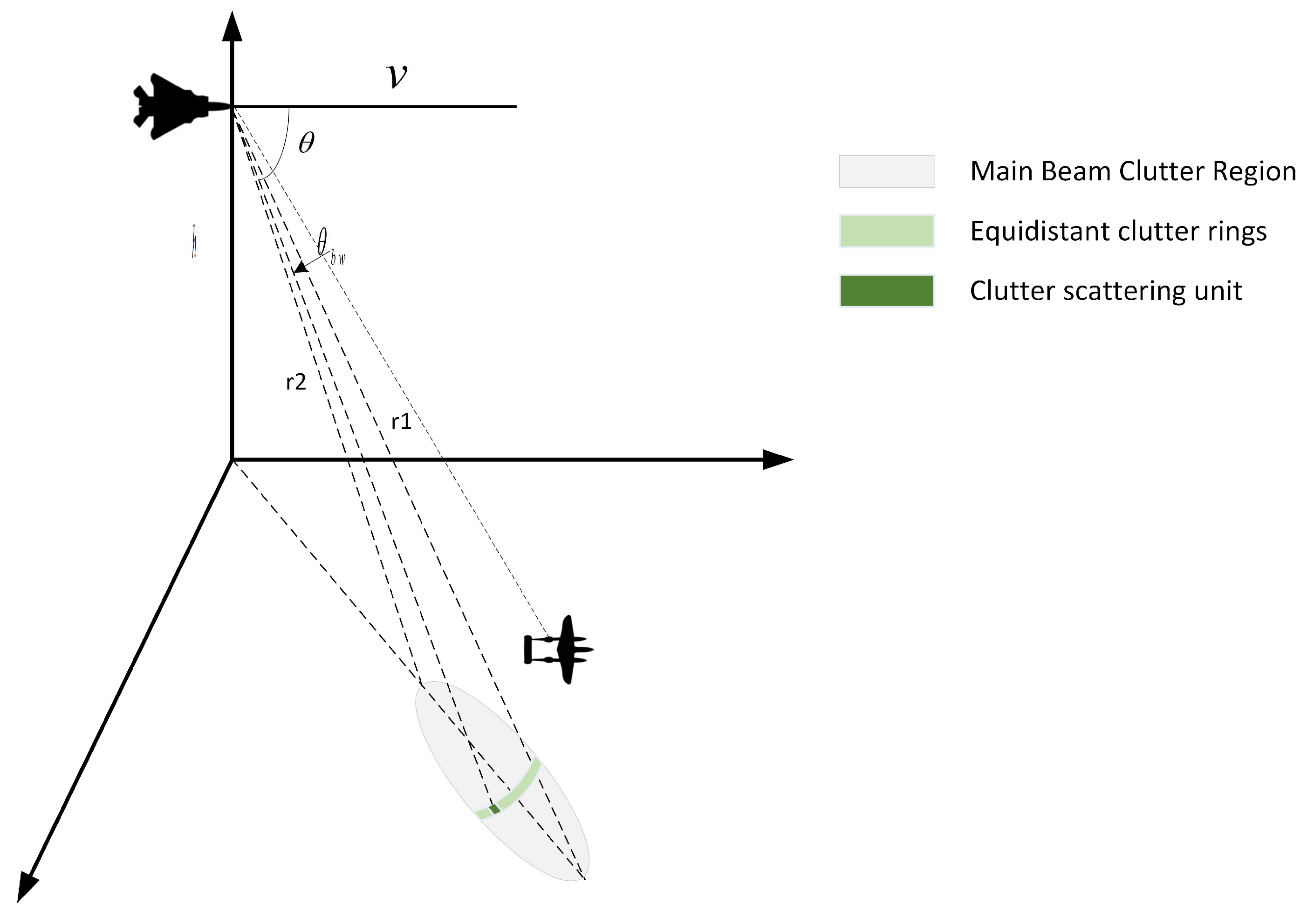
Figure 1 illustrates the down-looking scene of an airborne radar, showing clutter echoes that resemble target echoes. Clutter power can be quantified by the clutter scattering cross section
. In a radar system, the clutter region’s unit area can be represented as the equivalent scattering cross section per unit area, denoted as:
where
refers to the unit area of clutter and
denotes the clutter scattering coefficient, which follows the clutter statistical characteristics mentioned above.
The Doppler spectrum of stationary ground clutter broadens in the Doppler dimension when observed by a down-looking airborne radar, due to varying radial velocities of different angles within the radar beam. The clutter’s Doppler spectrum width is influenced by the aircraft speed, wavelength, and beamwidth.
The Doppler frequency of ground scatter echoes depends on the aircraft velocity and the angle between the scatter point and the aircraft’s velocity vector. It can be formulated as:
where
v represents the velocity of the carrier aircraft and
denotes the angle between the clutter point-to-radar vector and the velocity vector of the radar, and
is the wavelength of the radar system.
In general, the clutter area within the main radar beam has a significant impact on target detection. We assume that the radar beamwidth is
and the radar beam center slant angle is
, and the radar beamwidth is relatively small. The Doppler bandwidth and the Doppler center of ground clutter can be approximated as:
Assuming the aircraft altitude is
h, the clutter distance from the leading edge to the trailing edge of the main beam can be denoted as:
As radar typically transmits fixed PRF signals, target and ground clutter echoes will suffer from range ambiguity and velocity ambiguity in the received echoes, as shown in
Figure 2. For a given PRF, the maximum unambiguous range of the radar can be denoted as
, and the maximum unambiguous velocity as
.
Assuming the distance and Doppler of a certain scatter point are
R and
, respectively, the observable distance and Doppler of the radar can be expressed as:
where
l represents the number of range ambiguities and
g represents the number of Doppler ambiguities.
To mitigate ambiguity in radar echo signals from targets and ground clutter, a single fixed PRF signal may not provide accurate target information. Hence, a conventional approach involves employing multiple signal groups with different medium PRFs (Multi-MPRF) for detection. By varying the PRF, which affects both the maximum unambiguous range and velocity, the ambiguous region of the clutter spectrum can be adjusted.
Target detection is performed by obtaining range-Doppler results for each PRF set. However, when the clutter power exceeds the target power, the target may be obscured by the clutter. In such cases, the target’s presence and the number of target detections can be determined by establishing a set of rules.
Figure 3 illustrates this scenario. Assuming three PRF sets are employed for target detection, the target’s existence can be confirmed if it is detected twice. If the target lies within the clutter overlap region and remains undetected in two PRF sets, a target miss occurs.
Utilizing the RD map of different PRF echoes and applying the Chinese remainder theorem for ambiguity resolution enables accurate determination of the target’s distance and velocity. However, the conventional Multi-PRF approach independently detects targets in each PRF signal group, leading to degraded target detection performance in low SNR conditions due to inefficient use of energy within the main beam time. Modern non-coherent detection methods using multiple sets of RD results suffer from inconsistent range cells across PRF signals, resulting from large time gaps between PRF groups, which hinders effective non-coherent accumulation for high-speed targets that exhibit significant start position variations in different PRF echoes. Additionally, the presence of matching errors poses challenges in resolving distance and Doppler ambiguity.
2.2. PRF Interleaved Transmission and Echo Model
We propose a novel airborne radar mode that addresses the coherence issue in traditional multi-PRF systems. This mode involves interleaved transmission of multiple low PRF signal groups, each utilizing orthogonal discrete frequency coded (DFC) signals. The first pulse of each group is interleaved, followed by sequential emission of subsequent pulses based on each group’s PRF. Echo processing involves matched filtering to filter out signals from other PRF groups, enabling coherent processing based on the pulse transmission interval. This approach enhances target detection performance in low SNR conditions by obtaining high SNR results and improving target detection performance.
As shown in
Figure 4, the PRF interleaved transmission model assumes the existence of
N PRF signal groups, each using a different encoded DFC signal. It is also assumed that the radar alternates the transmission of N sets of DFC waveforms, with the start times of the signal transmissions being
. The PRI of the signals for different PRF groups are denoted as
. The
nth pulse group transmission of the radar can be expressed as:
where
is the center frequency of the radar system.
In Equation (
9),
denotes the DFC waveform used by the
nth PRF signal group, which can be denoted as:
where
is a rectangular function,
M is the number of frequency chips in a pulse,
is the time width of the frequency chip,
is the entire pulse time width,
is the frequency encoding sequence,
is the frequency interval of the frequency chips, and
.
is the pulse frequency coding coefficient in the
nth PRF signal group, which is randomly rearranged by
.
Assuming that
K pulse signals are transmitted for each PRF signal group during a beam dwell time, the transmitted signal can be represented as:
Let
, the echo signal of each PRF signal group can be represented as follows:
where
represents clutter signal, while
represents target signal.
For ground echoes, the echo signals of each PRF group can be represented after frequency down-conversion as:
where
refers to the clutter unit echo intensity,
corresponds to the phase of the clutter unit, and
denotes the Doppler of the clutter unit.
For a target, assuming the initial distance is
and the velocity is
, the echo of each PRF group can be represented as:
where
denotes the intensity of the target echo, while
represents the distance of the target at each pulse time. Due to the use of wideband signals, it is necessary to account for the target’s movement across distance cells during the observation time.
4. Simulation Results
The radar down-looking target detection introduced in this paper offers the advantage of performing coherent accumulation processing of all pulses in the entire coherent processing interval. It enables coherent processing of the Doppler spectrum to resolve ambiguity by obtaining range-Doppler results using orthogonal signals from multi-PRF. This section assesses the effectiveness of coherent processing in resolving Doppler ambiguity and extends it to typical airborne radar down-looking mode target detection. The proposed method’s validity is verified based on the target’s track integrity. For comparison, the traditional Multi-MPRF method, LPRF, and HPRF working modes are analyzed in target track detection.
4.1. Effectiveness Analysis of Doppler Ambiguity Resolution with Coherent Processing
The introduced airborne radar down-looking target detection method utilizes the staggered-PRF transmission mode. It integrates multi-PRF ambiguity resolution coherently based on pulse transmission timing. Firstly, the method conducts coherence validity analysis of the multi-PRF pulse group signals, disregarding the influence of target distance. The radar samples the target’s Doppler frequency, 3300 Hz, using three PRFs: 4000 Hz, 3900 Hz, and 4100 Hz, with a first sampling interval of 80
s and sampling 128 times per PRF. The DFT results for the range bins where the targets are located are depicted in
Figure 7a, indicating Doppler frequency ambiguity for the targets.
During coherent processing, the Doppler frequency is subject to ambiguity. Coherent processing is applied to each Doppler point within the range of [−5000 Hz, 5000 Hz]. For ambiguous Doppler frequencies, coherent processing is only conducted when all three PRFs exhibit ambiguity and the signal amplitude is assessed. If the selected post-ambiguous frequency values all contain peak amplitudes, the corresponding peaks are either set to zero or assigned a small value (effectively discarding the selected frequency point as it does not represent a real target).
As shown in
Figure 7b, in the range of Doppler frequency, due to the existence of Doppler ambiguity, there is a period extension under different PRFs. Only at the frequency of 3300 Hz, the DFT results of the three PRFs coincide.
By eliminating false frequency points, the correct result of resolving ambiguity can be obtained, as shown in
Figure 8.
The results of resolving ambiguity and coherent processing for three PRFs are shown in
Figure 8a. The output reveals a single peak at 3300 Hz, indicating successful elimination and suppression of ambiguous components in the Doppler frequency. The remaining energy is below 50 dB.
Figure 8b illustrates the comparison of normalized Doppler spectra before and after coherent processing, where coherent processing is performed using a staggered PRF signal group with
. After coherent processing, the signal gain is enhanced by a factor of
, as observed from the results. The peak output energy is increased by 9.5 dB, consistent with theoretical expectations. In the presence of noise, the noise energy is increased by a factor of
after coherent processing, leading to an improved SNR by
times. However, the figure shows the presence of high sidelobes near the mainlobe, which can be mitigated through windowing.
DFT-induced high sidelobes necessitate sidelobe suppression using windowing. The following results compare the outcomes before and after applying a Hamming window.
Figure 9a illustrates that windowing reduces the remaining coherent energy to below −60 dB, thereby enhancing the suppression of ambiguities.
Figure 9b demonstrates that the coherence performance remains unaffected by the addition of the window. Even after coherence processing, the signal energy remains 9.5 dB higher compared to before coherence processing.
In target detection, verifying the capability of coherent processing for ambiguity resolution in the presence of multiple frequencies, considering multiple targets with different Doppler frequencies in a range bin, is essential. For this purpose, a simulation experiment is conducted with three targets having Doppler frequencies of 3300 Hz, 1251 Hz, and −1300 Hz, respectively.
Figure 10a displays the DFT results of different PRFs in the presence of multiple targets, where each repetition frequency exhibits three peaks.
Figure 10b demonstrates the outcome of coherent processing for ambiguity resolution of the multiple targets. It is observed that the correct Doppler frequency manifests as a peak, which is the target, while the ambiguous false target is suppressed.
The results of coherent processing before and after multi-target’s ambiguity resolution are shown in the
Figure 11. It can be seen from
Figure 11 that multi-target’s Doppler frequencies have obtained coherent processing gains, which are 9.5 dB higher than the energy before coherent processing.
The above experiments have verified the coherent processing ability of the multiple PRFs in this paper to solve Doppler ambiguity of the target, and then verify the effectiveness of the airborne down-looking target detection working mode.
4.2. Multi-PRF Result Analysis of Airborne Radar with Orthogonal Signals
This section simulates the entire process of airborne radar down-looking mode using the proposed method. The simulation involves the use of five different PRFs for staggered-transmission in the down-looking mode. Each group employs different DFC signals. The PRFs for the five groups of signals are [4.3 kHz, 4.2 kHz, 3.7 kHz, 3.5 kHz, 4.1 kHz], with the corresponding start times of the first transmit pulse being [0 s, 32.6 s, 88.4 s, 144.2 s, 195.3 s]. Assuming a target distance of 12 km, a target speed of −45 m/s, and the target being coincident with the clutter front, it is assumed that the 5 PRFs are unaffected by clutter, thus placing the targets within the noise region.
Airborne radar simulation parameters are shown in
Table 1.
Radar antenna parameters are shown in
Table 2.
According to the antenna simulation parameters, the antenna pattern has a beam width of approximately 4 and a maximum gain of 53 dB.
The simulation sets the aircraft’s flight altitude to 8000 m and its heading speed to 100 m/s. The simulated ground clutter range is 34.8 km × 34.8 km. Based on the aircraft track and antenna pattern, the corresponding antenna gain for each ground grid can be calculated. Within the main beam’s irradiation range of the ground clutter, the Doppler bandwidth is approximately 600 Hz.
For the echo simulation of each PRF signal group, clutter, and target parameters, DFT processing is performed without noise. The DFT frequency interval is set to 100 Hz, and the RD maps of the four PRF signal groups are depicted in
Figure 12. The figure reveals that the target’s Doppler frequency is 3900 Hz. After DFT processing, the ambiguous frequencies for different signal groups are [−400 Hz, −300 Hz, 200 Hz, 400 Hz, −200 Hz]. The clutter Doppler center is at 4600 Hz, and there are ambiguities in various PRF signal groups.
Performing ambiguity resolution and coherent fusion processing between multiple frames is based on the initial moment of each frame signal transmission. Doppler ambiguity is resolved by selecting data according to the corresponding ambiguity Doppler index for each Doppler spectrum line, followed by coherent processing on the selected data.
Figure 13a displays the processing results without noise.
In the figure, the correct Doppler spectrum for the target and the clutter area (around 4900 Hz) exhibits significant energy, while the remaining ambiguous areas contain only residual energy. For a clearer analysis of the coherent effect and ambiguity suppression performance, the signal from the range bin containing the target is examined.
Figure 13b presents the Doppler spectrum of the target’s range bin. In the figure, the target’s Doppler is accurately resolved and its coherent accumulation achieves an energy gain of 13.38 dB, close to the theoretical value of 13.97 dB. In non-target areas, there is residual energy from Doppler ambiguity resolution, resulting in energy distribution in some regions. The energy of ambiguity resolution is suppressed by approximately 50 dB.
The experiments above confirm the accuracy of Doppler ambiguity and the coherent gain of target energy. In practical applications, performing coherent processing of ambiguity resolution on every range-Doppler cell within the power range requires extensive computation. To reduce the computational load, first-layer detection of the echo signal can be employed. Firstly, the RD results of each PRF signal group are detected using a lower first detection threshold (7 dB).
Figure 14 illustrates the schematic diagram of CFAR detection. Then, based on the detection results, Doppler ambiguity resolution and coherent fusion are performed, followed by a second-layer detection on the fusion results.
Figure 15 presents the RD result of the first PRF signal group. The detection result using the first detection threshold is depicted in
Figure 15b, where numerous false alarms are observed. For ambiguity resolution and coherent fusion processing using the multi-PRF signal group, the simulation applies a second detection threshold (13 dB) to detect the signal after ambiguity resolution. The comparison between the first and second CFAR detections is shown in
Figure 16.
In
Figure 17, coherent processing of the RD results from multiple PRF groups leads to a corresponding increase in the detection threshold. The target energy experiences a five-times SNR gain through coherent processing. Simulation raises the threshold (i.e., the second detection threshold) to 13 dB, surpassing the noise level.
Figure 17b displays the detection result of the second detection threshold. After coherent processing and the second detection, only the target signal is output, eliminating all false alarms.
Compared to the traditional Multi-PRF method, within the same dwell time, which sequentially transmits five groups of PRF waveforms and performs ambiguity resolution processing after detecting the RD results of each group. Utilizing low PRFs in PRF cross-transmission extends the maximum unambiguous distance than the traditional method, avoiding the division of the entire dwell time into multiple parts. Consequently, the coherent processing time is longer (with a larger slow-time domain sampling width), resulting in improved target energy and Doppler resolution.
As shown in the figure above,
Figure 18a shows the traditional Multi-PRF at 20 KHz repetition frequency, accumulating 256 pulses, the Doppler resolution is 103 Hz, and
Figure 18b shows the use of alternate PRF in this way, and the Doppler resolution is 20 Hz. After coherent processing, the Doppler resolution is less than 20 Hz, and the Doppler resolution is five times higher than that of Multi-PRF.
4.3. Target Detection Clutter Avoidance and Track Integrity Analysis
The previous experiments verified Doppler ambiguity resolution and coherent accumulation for targets and clutter. To further analyze target occlusion by clutter, the track integrity detection method is employed for comparison. Simulated targets can be obstructed by ground clutter. Radar parameters are consistent with previous experiments, with an antenna beam pointing of 50 in azimuth and 50 in elevation. Based on radar height, radar speed, and beam pointing angle, the clutter Doppler center is determined to be 2589.2 Hz, with a clutter Doppler bandwidth of 1093.7 Hz, and ground clutter distribution ranging from 14.1 Km to 17.4 Km. The genetic algorithm optimizes the PRF based on the clutter Doppler spectrum, resulting in five optimized PRF groups: [5758 Hz, 4827 Hz, 4262 Hz, 5243 Hz, 4022 Hz].
For comparison, LPRF, HPRF, and traditional multi-MPRF working modes are used. LPRF is set at 1.5 KHz, HPRF at 100 KHz, and traditional Multi-MPRF as [17 kHz, 19 kHz, 17.3 kHz, 19.2 kHz, 19.8 kHz]. Under LPRF, distance ambiguity is absent, but Doppler ambiguity is more severe, with clutter Doppler widely distributed on the RD map. When the target’s distance and ambiguity-resolved Doppler coincide with the clutter Doppler distribution, accurate target detection becomes challenging. Extracting the target’s velocity information is also problematic due to Doppler ambiguity. With HPRF, distance ambiguity in the RD result is more severe, and clutter is widely distributed in the distance cell corresponding to the target’s Doppler spectrum. Consequently, when the target’s Doppler coincides with clutter Doppler, the target is submerged in clutter and remains undetected. Even if the target is not obscured by clutter, accurate extraction of the target’s distance information is impossible due to significant distance ambiguity. The multi-group MPRF method minimizes clutter Doppler spectrum obscuring the target, but separate detections within a dwell time prevent full utilization of transmitted signal energy, resulting in missed target detection under low SNR conditions and reduced radar power range.
In the simulation, a target within the radar field of view starts moving away from the radar at a distance of 2 km, accelerates, decelerates, and hovers over the ground. The target’s trajectory within 200 s is simulated, and target detection is performed in clutter. The speed and distance of the target during the simulation time period are shown in
Figure 19.
Assuming the radar transmission power is 10 kW and the target’s RCS is 0.1 m
. According to the target distance and radar equation, after multi-pulse coherent processing, the power of the target throughout its trajectory can be obtained, and the result is shown in
Figure 20.
To ensure an equivalent comparison, the radar is configured with the same transmission energy during each dwell time, resulting in a fixed average transmission power. Under LPRF, the pulse signal exhibits high instantaneous power, while HPRF demonstrates low instantaneous power. After coherent processing, the echo power is calculated for each PRF. LPRF and HPRF maintain full coherence throughout the dwell time, resulting in equal echo power for the target. In the case of traditional multi-group MPRF, five groups of MPRF signals are used, and each group is separately detected, resulting in coherent performance of only 1/5 of the total energy. The method proposed in this paper uses three groups of signals in five groups for coherent accumulation detection, resulting in coherent processing performance equivalent to 3/5 of the total energy.
During the simulation process, the received echo’s noise power is set to −64 dBw. The detection results of the target at different PRFs throughout the entire track are depicted in
Figure 21.
Figure 21 reveals that traditional Multi-MPRF exhibits low-target SNR due to limited coherent processing within each group, resulting in the inability to detect targets beyond a distance of 13.2 km. In LPRF mode, stable target detection is achieved when the target is far from the ground. However, during the target’s hovering phase above the ground, robust detection is hindered by the overlap between the target and ground clutter Doppler spectrum, where the target power is lower than the clutter power. This leads to missed detections during the time periods of 116–136 s and 166–186 s. In HPRF mode, severe distance ambiguity creates blind zones within the ground clutter Doppler spectrum and in each range bin. Consequently, missed detections occur at any distance when the target Doppler was covered by the clutter Doppler spectrum. The multi-group LPRF cross-transmission designed in this paper, optimized to minimize blind zones and enable ambiguity resolution, exhibits minimal missed detections throughout the target’s trajectory.
Using solely LPRF or HPRF poses limitations in accurately extracting both distance and velocity parameters of the target simultaneously.
Figure 22 displays the experimental measurement results for target distance and velocity.
Figure 22 illustrates that LPRF, Multi-MPRF, and the proposed method accurately extract target distance, whereas HPRF suffers from severe distance ambiguity and cannot accurately reflect the true target distance. In terms of target speed estimation, HPRF, Multi-MPRF, and the proposed method provide accurate results, while LPRF exhibits speed ambiguity within the detectable range. The proposed method employs a range-speed ambiguity resolution technique similar to traditional Multi-MPRF, enabling simultaneous and accurate estimation of target distance and speed. Additionally, by utilizing at least three groups of signals for coherent processing within five groups, the proposed method achieves a three-times increase in SNR gain, expanding the theoretical power range of the radar by 1.48 times compared to traditional Multi-MPRF.
In the experiment, Newton interpolation was applied to estimate the target distance and speed based on the detection results.
Figure 23 displays the parameter estimation error results. Analysis of the distance error is limited to LPRF, traditional Multi-MPRF, and the proposed method, while speed error analysis covers only HPRF, Multi-MPRF, and the proposed method. Traditional Multi-MPRF exhibits a smaller SNR gain from signal processing, leading to larger measurement error variance within the detectable segment compared to the other three methods. The proposed method, performing coherent processing within three groups of five PRFs, yields a relatively smaller SNR in signal processing compared to LPRF and HPRF. Consequently, distance measurement error variance is slightly larger than that of LPRF, while speed measurement error variance is slightly larger than that of HPRF.
These findings demonstrate the effectiveness of the proposed method in detecting airborne targets in the radar’s down-looking mode, accurately extracting target distance and speed information, and achieving an extended operating distance (power range) compared to traditional Multi-MPRF methods for resolving two-dimensional ambiguity between range and Doppler.


