Abstract
Observation task planning is a key issue and the first step in the development of automated Satellite Laser Ranging (SLR) systems. Aiming at the problem of dynamic change of cloud cover during SLR operation, this paper proposes an autonomous mission planning algorithm for SLR based on the Rolling Horizon Optimization (RHO) framework. A hybrid event- and cycle-driven replanning mechanism is adopted, and four functional modules, rolling, planning, information acquisition and decision-making, are established to decompose the SLR observation task planning process into a series of static planning intervals. An improved ant colony algorithm is proposed and utilized to realize the autonomous planning of SLR system observation tasks, and the above autonomous planning algorithm is verified and analyzed based on the SLR system at station 7237. The results show that the above algorithm can effectively increase the number of observation satellites and revenue under cloud disturbance, solve the problems of low efficiency and poor interference resistance of conventional static algorithms, and provide a new research idea for the establishment of an unattended SLR system.
1. Introduction
Satellite laser ranging (SLR) technology is a multidisciplinary technology combining laser, photoelectric detection, automatic control, satellite orbit and other technologies [1,2]. Unlike other space geodesy techniques, SLR uses high heavy frequency, high peak power and narrow pulse width lasers, which solves the problems of low ranging accuracy, poor stability and bulky equipment in traditional radar systems, and has been widely used in astronomical geodynamics, space geodesy and space science research [3,4,5,6]. In order to meet the major national needs of manned spaceflight, satellite navigation systems and deep space exploration, SLR systems are developing towards long-range, high-precision and automation. Due to the expensive equipment and technical difficulties, only NASA of the United States, Stromlo of Australia and Wettzell of Germany have realized research into an unattended fully automatic satellite laser ranging system [7,8,9,10].
With the continuous expansion of the application field, the SLR cooperation targets are increasing year by year: how to use the observation task planning technique to arrange the repetitive and large number of SLR observation tasks in the observation window reasonably; to obtain the optimal observation effect—one of the difficulties to be solved urgently to improve the efficiency of the SLR system; to realize the automation of the station. At present, most SLR stations still use manual planning to select observation targets. This method has a poor degree of automation and low efficiency, and is prone to leakage of stars and fewer stars in the observation process, which cannot give full play to the effectiveness of the high-precision SLR system.
Much of the research on observational task planning issues has centred on aspects such as Earth observation satellites and imaging satellites. Conventional observation task planning is usually based on observation task information, building a mathematical model, designing a static planning algorithm to solve it, and generating observation plans for days or even weeks [11,12]. However, in actual observations, there are situations where clouds obscure the observation targets, and pre-generated observation plans are often severely disrupted. In order to solve this problem, some scholars have developed observation plans based on static planning algorithms, which are based on the predicted cloud information provided by the meteorological department. In 2007, Liao et al. converted the observation task planning problem into a stochastic integer planning problem, combined with weather prediction information, and utilized a Lagrangian relaxation algorithm to generate a planning scheme, which was adjusted according to the updated weather prediction information [13]. In 2013, He et al. developed a model for the impact of cloud cover on the observation task based on cloud prediction information and designed a heuristic algorithm to solve the problem [14]; Wang et al. represented the cloud cover occlusion at the time of observation as a stochastic event, established an integer linear programming (ILP) model, and proposed a branch and cut (B&C) algorithm based on delayed constraint generation to solve the ILP model [15]. In 2022, Li et al. first analyzed the cloud information provided by meteorological satellites and proposed a task planning algorithm solving for generated observation plans based on cloud information [16].
Unlike in the above studies, the observation results and accuracy of SLR systems are highly susceptible to the influence of cloud cover, and the observation plans generated using the predicted cloud information cannot meet the requirements of SLR applications. For this reason, this paper proposes an autonomous planning method for SLR observation tasks based on the Rolling Horizon Optimization (RHO) framework for dynamic changes of cloud cover. The task planning process is decomposed into a series of continuous uninterrupted static planning intervals based on real-time cloud information and rolling windows. At the same time, an improved ant colony algorithm is designed to solve the problem, continuously carry out planning and decision-making, and utilize the local planning several consecutive times instead of one-time global planning, so as to reasonably arrange the repetitive and large number of SLR observation tasks within the observation window, and to realize the autonomous planning of observation tasks in the SLR system, so as to enhance its degree of automation and work efficiency.
2. Problem Analysis
2.1. Problem Description
In the SLR observation task planning problem, there are phenomena such as multiple targets transiting at the same time, different target priorities, time window constraints between targets and stations, and cloud cover obscuring the observation targets during the observation process [17], as shown in Figure 1. How to achieve autonomous avoidance of clouds in a specific observation time window and maximize the observation results to meet the satellite tracking priority and observation revenue is the primary problem to be solved in the autonomous task planning of the SLR observation task.
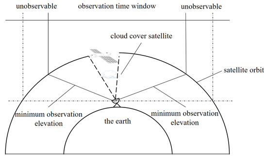
Figure 1.
Schematic diagram of station observation.
The satellite tracking priority is established by the International Laser Ranging Service (ILRS) organization based on satellite orbit parameters and special project requirements. The priority list is shown in Table 1 (partial).

Table 1.
Priority list (partial).
The 7237 observation station combines the priority list provided by ILRS to convert observation efficiency into observation revenue. Each satellite has three scores based on observation time. The higher the score, the higher the observation efficiency. The 7237 observation station rating table is shown in Table 2 (partial).
Table 2.
7237 observation station rating table (partial).
2.2. Decision Variables
Based on the above problem description, the decision variables for the SLR systematic observation task planning problem are expressed as follows:
Equations (1)–(4) represent the decision variables of the planning model. Among them, is a variable indicating whether the satellite is obscured by clouds. When is set to 1, it indicates that satellite i can continue to observe without being obscured by clouds. Otherwise, it is set to 0. , , respectively represent the observation duration variables of satellite i. When satellite i is observed, one and only one of the three variables is not zero. When satellite i is not observed, all three variables are zero.
2.3. Constraints to Be Met
In the task planning process of the SLR system, for a particular laser ranging station H on the ground, the satellite selected needs to satisfy the following constraints:
- The station is not visible to the satellite at all times, so there is a visibility time window constraint that needs to be satisfied for target selection;
- Satellites need to meet a certain elevation angle in order to carry out effective observations;
- Observation targets need to be selected based on a prioritized list of satellites provided by ILRS;
- The selection of the observation target should be such that the observable duration of the target is not less than the minimum duration;
- Once the target has been selected, there are only three choices of observation duration: minimum, qualified and full, corresponding to three scores;
- Observation start and end times for all targets should be within the task planning time frame;
- Observation targets must not be obscured by clouds.
2.4. Problem Modeling
The above constraints will affect the station’s selection of observation satellites, and these constraints are expressed in the constraint satisfaction model below:
In the above model, Equation (5) indicates that the optimization goal of SLR system task planning is to maximize the observation revenue, and Equations (6)–(11) indicate the constraints that need to be met for SLR observation task planning problems. The specific instructions are shown in Table 3:
Table 3.
Constraint Description.
3. Autonomous Planning Algorithm for Observation Tasks in SLR System
Based on the above constraint model, this paper adopts the Rolling Horizon Optimization (RHO) framework for the SLR system observation task. Rolling Horizon Optimization (RHO) is a framework of continuous short-term local optimization over time to achieve continuous online optimization [18,19,20]. A hybrid event- and cycle-driven replanning mechanism is used, with cloud cover of the satellite as a contingency. When an emergency occurs, an event driven replanning mechanism is adopted to immediately carry out replanning. Otherwise, a cycle driven replanning mechanism is adopted to continuously roll out planning and quickly respond to cloud dynamic changes. This method includes four functional modules: rolling, planning, information collection, and decision-making, with information transmission and feedback between the modules, as shown in Figure 2.
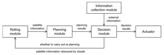
Figure 2.
The relationship between modules.
3.1. Rolling Module
The rolling module is responsible for creating rolling windows [21]. For the SLR system observation task autonomous planning problem, the role of the rolling window is mainly to establish the static planning interval, combined with the decision-making module passing the information of the satellite obscured by clouds, to obtain the information on observable satellites within the interval, and pass it to the planning module, as shown in Figure 3. The flow of the rolling module is shown in Figure 4.
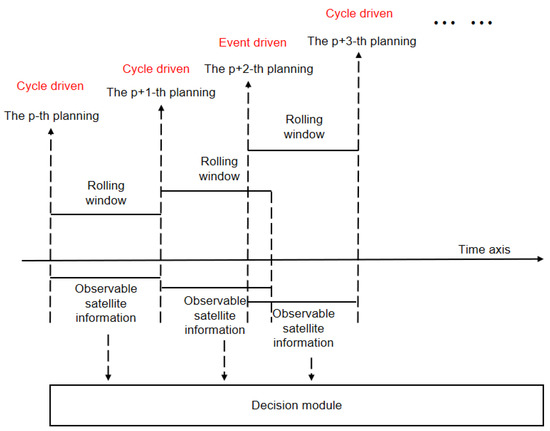
Figure 3.
Schematic diagram of rolling window.
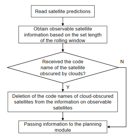
Figure 4.
The flow of the rolling module.
3.2. Planning Module
The planning module is responsible for planning observable satellites within the rolling window, often using static planning algorithms. The ant colony algorithm is one of the preferred algorithms for static planning and has high computational speed in solving optimization problems [22,23]. In this paper, the ant colony algorithm is improved by combining the ideas of the greedy algorithm and wolf pack algorithm according to the established constraint model of the problem. The details are as follows:
3.2.1. Node Transfer Improvement
In this paper, the greedy algorithm is introduced to improve the node transfer of ants, which not only solves the problem of large randomness in the node transfer of the ant colony algorithm, but also meets the principle of satellite tracking priority for the SLR system. There are two methods for the improved node transfer as follows:
Method 1: At the time of node transfer, the set of observable satellites exists, and there are unobserved satellite sets . The observed satellites are placed in the taboo list , meeting the requirements . At this point, node transfer is carried out through Greedy Algorithms for satellite selection from . The greedy criterion set in this article is satellite priority [24,25]. After finding the satellite with the highest priority for the current node, the ant colony algorithm is used for processing, and the observation time of the satellite is selected through the roulette wheel method. This not only satisfies satellite priority, but also relies on the dynamic optimization characteristics of the ant colony algorithm to obtain the optimal observation sequence. The roulette wheel expression is:
In the formula, represents the probability that ant will transfer from Node to Node at time , and select the next node based on the roulette wheel method, where represents the pheromone content on the path at time ; represents heuristic information on path at time ; and is the pheromone heuristic factor, representing the importance of pheromone to path selection. The greater the , the greater the role of the pheromone in selecting the next node; is the expected heuristic factor, and the larger the , the greater the role of heuristic information in path selection; is the set of next paths that can be selected.
Method 2: At the time of node transfer, indicates that the set of satellites can be observed, while the unobserved set of satellites is . At this time, the node transfer is consistent with the traditional ant colony algorithm, and the next observation target and its observation time are selected according to the roulette wheel method.
At the moment of node transfer, if there are unobserved satellites, the satellite with the highest priority among them is to be preferred, when the node is transferred in method 1; if there are no unobserved satellites, all satellites are randomly selected, at which point the node is transferred in method 2.
3.2.2. Improvement of Pheromone Updating Method
In order to ensure that the computational speed of the algorithm meets the requirements of the planning module, this paper is based on the idea “the weak is strong and the strong is strong” in the wolf pack algorithm [26], which penalizes the paths other than the optimal paths in each iteration, and reduces their pheromone concentration:
where represents the updated pheromone concentration; represents the volatilization coefficient of pheromone; represents the sum of pheromone increments of all ants; represents the pheromone increment of ant on path ; represents the pheromone strength, which is a constant; is the total score of ant in this cycle; represents the planned termination time; represents the planning start time; represents the penalty function for the path ; represents the penalty coefficient; represents the optimal path in this iteration; and represents the paths other than the optimal path in this iteration.
By updating the pheromone on the path through Equation (14), the differentiated path information of the ant colony in the iterative process is utilized to increase the guiding effect of the better ants in the colony for the progeny, which reduces the interference of the worse ants on the path search, and improves the computational speed of the algorithm.
Figure 5 shows the flowchart of the improved ant colony algorithm. The process is as follows:
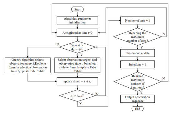
Figure 5.
Algorithm flow chart.
- Step 1:
- Receive observable satellite information transmitted by the rolling module, and initialize algorithm parameters;
- Step 2:
- Place all ants at time t = 0 and prepare to launch;
- Step 3:
- At time t, to determine if the unobserved satellite set is . If it is , continue to step 4. If it is not , jump to step 5;
- Step 4:
- Use Equation (12) to select observation target and its observation time from the observable satellite set , add the target to taboo table , and update the taboo table;
- Step 5:
- Use the greedy algorithm to select observation target from the unobserved satellite set and the selection of target observation time utilizes Equation (12), while updating the taboo table , and update the taboo table;
- Step 6:
- If the ants reach the end of the task planning interval, continue to the next step, otherwise jump to step 3;
- Step 7:
- Number of ants + 1. If the maximum number of ants is reached, continue to the next step; otherwise, jump to step 2;
- Step 8:
- Update the pheromone with Equation (13);
- Step 9:
- Iterations + 1. If the maximum number of iterations is reached, continue to the next step; otherwise, jump to step 2;
- Step 10:
- Output the observation plan with the highest revenue, and the algorithm ends.
3.3. Information Collection Module
In this paper, a hybrid-driven replanning mechanism is used and the satellite is obscured by clouds as a contingency. When an emergency occurs, an event-driven replanning mechanism is used for immediate replanning, otherwise a cycle-driven replanning mechanism is used for continuous rolling planning to quickly respond to dynamic changes in the cloud cover [27]. To determine whether the satellite is obscured by clouds, an all-sky camera is used to obtain information on cloud cover over the station. Setting the sampling moments with fixed time intervals, the information acquisition module transmits the information to the decision-making module at each sampling moment, and the decision-making module makes a judgment on the relationship between the satellite and the cloud cover.
The information collection module is responsible for obtaining the pixel position of the cloud cover from the image acquired by the all-sky camera at each sampling moment. In this paper, we use the image processing method to separate the sky background from the cloud cover and pass the cloud position information to the decision module, and the separation result is shown in Figure 6.
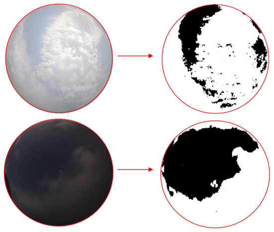
Figure 6.
Separation results of sky background and cloud cover.
3.4. Decision Making Module
3.4.1. Decision Output
When each sampling moment arrives, the decision module obtains the observation satellite i at the current sampling moment from the planning results passed by the planning module, and combines the cloud information passed by the information collection module to determine whether the observation satellite i is obscured by clouds. The decision module will output two different decision results according to the different judgment results, which are:
Decision 1: When the observation satellite i is obscured by clouds, the decision module obtains the observable satellite information at the current sampling time, removes the satellite i obscured by clouds from the observable satellite information, selects the satellite with the highest priority among the remaining satellites, makes a judgment again until the observation satellite k is selected, and outputs satellite k as the observation satellite from the current sampling time to the next sampling time. At the same time, the decision module, based on the event-driven replanning mechanism, passes the information o, the remaining satellites that have not been obscured by clouds and the replanning signal to the roll module to initiate a new round of rolling.
Decision 2: When satellite i is not obscured by clouds, output satellite i as the observed satellite from the current sampling moment to the next sampling moment. At the same time, the decision module judges the sampling moment; if the next sampling moment is the end of the rolling window, then according to the cycle-driven replanning mechanism, the replanning signal will be passed to the rolling module to start a new round of rolling.
3.4.2. Cloud and Satellite Position Determination
In order to determine whether the satellite is obscured by clouds, the satellite position information is converted to the same coordinate system as the cloud position information for evaluation, and the conversion steps are as follows:
- Step 1:
- Obtain the ground fixed coordinates of the satellite at the current sampling time from the satellite predictions, and convert the satellite’s ground fixed coordinates into a point in the camera coordinate system;
- Step 2:
- Based on the imaging principle of a pinhole camera, obtain the image point of point without distortion, represented in polar coordinates as , and the projected incidence angle of point as ;
- Step 3:
- Due to the presence of distortion, the actual angle of light emission is , and the actual image point is ;
- Step 4:
- Using the equidistant projection formula and Taylor expansion can approximately obtain , where is the camera distortion parameter, which is provided by the camera calibration results;
- Step 5:
- Because of , the polar coordinate of point is , and the Cartesian coordinate value , is obtained;
- Step 6:
- Finally, convert to the pixel coordinate system based on the camera’s internal parameters, , .
Through the above steps, the satellite position is converted to the pixel coordinate system to determine whether the satellite is obscured by clouds. Figure 7 shows the schematic diagram of the satellite position information coordinate conversion process.
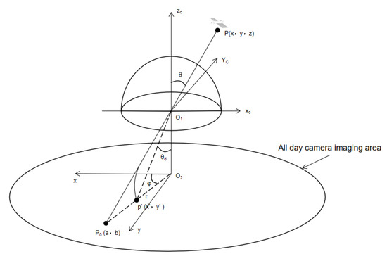
Figure 7.
Coordinate conversion of satellite position information.
4. Experiments and Analysis
In order to verify the performance of the autonomous task planning algorithm for satellite laser ranging based on the Rolling Horizon Optimization framework, two sets of simulation experiments are conducted based on the 7237 station SLR system. The first set of experiments is a cloud environment simulation experiment to verify the ability of the autonomous planning method to avoid cloud cover for observation task planning; the second set of experiments is an algorithm comparison experiment, in which the autonomous planning method is simulated with two static planning algorithms in cloud environments with different occupancy ratios to validate the advancement of this paper’s method in dealing with the planning problem of observation tasks in SLR systems.
4.1. Cloud Environment Simulation Experiment
In the actual observation process of the SLR system, the observation results are susceptible to the influence of cloud disturbances. For this purpose, three experiments are conducted, and one disturbance is set up in each experiment; the cloud disturbance moments are shown in Table 4, and the simulation tasks are given in Table 5.
Table 4.
Disturbance settings.
Table 5.
Simulation task list.
Figure 8 shows the results of three cloud disturbance experiments. In experiment 1, the decision module received a signal that satellite L2 was obscured by clouds at 6 min. As can be seen from the results of Experiment 1, the decision module performs automatic cloud avoidance, selects satellite BP to continue the observation, and reformulates the planning. In experiment 2, the decision module received a signal that satellite L2 was obscured by clouds at 11 min. As can be seen from the results of Experiment 2, the decision module performs automatic cloud avoidance, selects satellite BP to continue the observation, and reformulates the planning. In experiment 3, the decision module received a signal that satellite A6 was obscured by clouds at 20 min. From the results of Experiment 3, it is clear that the decision module automatically avoids the clouds, selects satellite HD to continue the observation, and reformulates the planning.
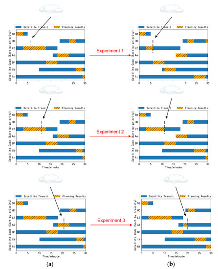
Figure 8.
Experimental results of cloud disturbance. (a) Results before inserting clouds; (b) results after inserting clouds.
Table 6 shows the results of the comparison of the revenue obtained from the observation according to the original planning sequence after setting up the cloud perturbation with that obtained from the re-formulated planning observation. From Table 6, it can be seen that after setting up the cloud disturbance, the revenue obtained from re-planning is higher compared to the revenue obtained from the original plan. This is due to the fact that the autonomous planning algorithm automatically avoids clouds and fully utilizes the observation time to search for other observable satellites, which improves the observation efficiency of the system and provides resistance to cloud disturbances.
Table 6.
Comparison of the revenue obtained from the original planning sequence and the replanning sequence after insertion of the cloud perturbation.
4.2. Comparative Experiments
In order to further validate the performance of the autonomous task planning algorithm based on the Rolling Horizon Optimization framework, the above algorithm and two static planning algorithms are applied to SLR observation task planning. The above algorithms are utilized to process the same observation tasks in simulated environments with different cloud amounts.
First, a cloud simulation environment is established. The simulated cloud was set as a circle, with an initial position tangent to the imaging area of the all-sky camera, and constantly moving along the image axis. At the end of the planning time, the cloud moves to the other side of the image of the all-sky camera and is at a tangent to the image, as shown in Figure 9, assuming that the cloud moves with a fixed speed in the image.
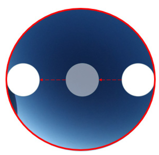
Figure 9.
5% simulation of cloud environment.
The SLR observation task example from 0–1 o’clock on 18 April 2023 was selected to conduct five experiments with simulated clouds occupying 0%, 5%, 10%, 20% & 40% of the imaging area of the all-day camera image, and the results are shown in Figure 10 and Figure 11, respectively. The comparison results are shown in Table 7, where the percentage improvement of autonomous planning algorithm compared to the ant colony algorithm and greedy algorithm is calculated as:
where α represents the percentage improvement of the autonomous planning algorithm compared to the ant colony algorithm and the greedy algorithm, represents the observation revenue or the number of satellites observed by the autonomous planning algorithm, and represents the observation revenue or the number of satellites observed corresponding to the ant colony algorithm and the greedy algorithm.
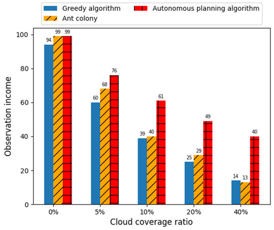
Figure 10.
Schematic diagram of the observation income at 7237 stations under different algorithms.
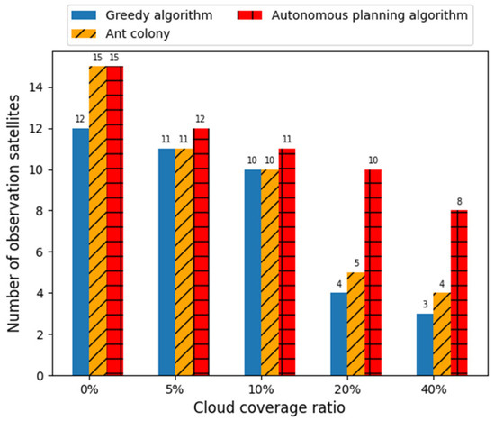
Figure 11.
Schematic diagram of the number of observation satellites at 7237 stations under different algorithms.
Table 7.
Comparison results of the autonomous planning algorithm with the ant colony algorithm and greedy algorithm.
Figure 10 shows the observation revenue of station 7237 under different algorithms. From Figure 10, it can be seen that when the sky is cloudless, there is not much difference between the revenues of the three algorithms. All three algorithms show gradually decreasing revenue when the percentage of cloud cover gradually increases, but the autonomous planning algorithm has a lower decrease in revenue than the other two static algorithms. Combined with Table 7, it can be seen that the greedy algorithm observation revenue decreases to 14, the ant colony algorithm observation revenue decreases to 13, and the autonomous planning algorithm observation revenue decreases to 40 when the cloud cover percentage reaches 40%. Compared to the greedy algorithm and ant colony algorithm, the autonomous planning algorithm observation revenue is improved by 185.71% and 207.69%, respectively. This is due to the fact that, in cloudy environments, clouds can interfere with the observations, and for static planning algorithms, the planning results are fixed. As the percentage of cloud cover gradually increases and the number of satellites obscured by clouds gradually increases, the revenue obtained by the static planning algorithms decreases dramatically. For the autonomous planning algorithm, when the observation satellite is obscured by clouds, the system will actively switch the observation target and re-plan the optimal observation sequence, which avoids the disturbance of clouds to a certain extent and ensures the observation revenue. Therefore, the autonomous planning algorithm obtains a higher observational revenue compared to the static planning algorithm in the face of cloud disturbance. The higher the percentage of cloud cover, the more obvious the advantage of the autonomous planning algorithm in terms of observation revenue.
Figure 11 shows the number of satellites observed at station 7237 under different algorithms. As can be seen from Figure 11, the number of satellites observed by all three algorithms decreases gradually when the cloud cover percentage increases gradually. When the percentage of cloud cover reaches 40%, the number of observed satellites decreases dramatically for the greedy algorithm and the ant colony algorithm, while the autonomous planning algorithm decreases to a lesser extent. At this time, the number of satellites observed by the greedy algorithm is three, the number of satellites observed by the ant colony algorithm is four, and the number of satellites observed by the autonomous planning algorithm is eight. The autonomous planning algorithm is significantly better in terms of the number of observed satellites compared to the greedy algorithm and ant colony algorithms. This is due to the fact that the static planning algorithms obtain a fixed observation target, whereas the autonomous planning algorithms can automatically avoid clouds and select satellites that are not obscured by clouds for observation, and are able to successfully observe more satellites. Therefore, the autonomous planning algorithm observes a larger number of satellites compared to the static planning algorithm in the face of cloud disturbance. The higher the percentage of cloud cover, the more obvious the advantage of the autonomous planning algorithm in terms of the number of satellites observed.
5. Conclusions
In this paper, for the dynamic change of cloud cover in the actual SLR observation process, an autonomous SLR task planning method based on the Rolling Horizon Optimization framework is proposed to solve the problems of poor automation and low efficiency in the existing SLR observation methods. This algorithm adopts a hybrid event and cycle driven replanning mechanism, establishing four modules: rolling, planning, information collection, and decision-making. The planning process is decomposed into a series of static planning intervals, and an improved ant colony algorithm is designed to handle tasks within the static planning interval. Design of experiments was pursued to validate the performance of an autonomous task planning algorithm for Satellite Laser Ranging based on a Rolling Horizon Optimization framework. The results show that the autonomous planning algorithm can automatically avoid cloud perturbations and re-plan when they occur, and has the ability to resist cloud disturbance. The higher the percentage of cloud cover, the more obvious the advantage of autonomous planning algorithms over static planning algorithms. When the percentage of cloud cover reaches 40%, the observation revenue obtained by the autonomous planning algorithm is improved by 185.71% compared with the greedy algorithm and 207.69% compared with the ant colony algorithm, and the number of observation satellites is significantly improved compared with the greedy algorithm and the ant colony algorithm. This work can be used to rationalize the repetitive and large number of SLR observation tasks within the observation window, to improve the efficiency and automation of the SLR system, and to lay the research foundation for the realization of research into an unattended and fully automated laser ranging system. The work of our future research is: (1) calculate the effect of cloud thickness on the echoes generated by targets at different orbital altitudes, and incorporate cloud thickness as a judgment criterion when performing autonomous planning; (2) based on the generated SLR observation plan, SLR intelligent subsystems, such as target tracking, observation and identification, are established to realize the development of an unattended and fully automated SLR system; (3) to carry out research on the planning of autonomous observation tasks for other high-precision laser ranging technologies, such as space debris laser ranging and lunar ranging, in order to expand the range of applications. These issues are expected to be addressed in further detailed studies.
Author Contributions
Conceptualization, C.F., N.A. and Z.L.; methodology, C.F., N.A. and Z.L.; software, C.F., N.A. and Z.L.; validation, C.F., N.A. and Z.L.; formal analysis, C.F., N.A. and Z.L.; investigation, J.G., G.W. and H.Z.; resources, L.M., X.D. and C.L.; data curation, L.M., X.D. and C.L.; writing—original draft preparation, Z.L.; writing—review and editing, Z.L.; visualization, Z.L.; supervision, C.F. and N.A. All authors have read and agreed to the published version of the manuscript.
Funding
This research was funded by the National Natural Science Foundation of China, grant numbers 12073052, 11973064, the Jilin Province Science and Technology Development Program, China, grant number 20230101006JC.
Data Availability Statement
Priority data can be obtained on the ILRS official website. The observation income data can be obtained from the observation manual used at station 7237. Other data can be obtained in the main text.
Conflicts of Interest
The authors declare no conflict of interest. The funders had no role in the design of the study; in the collection, analyses, or interpretation of data; in the writing of the manuscript; or in the decision to publish the results.
References
- Deng, H.; Zhang, H.; Long, M.; Wu, Z.; Tang, K.; Zhang, Z. 4kHz Repetition Rate Satellite Laser Ranging System and Its Application. Acta Opt. Sin. 2019, 39, 233–239. [Google Scholar]
- Shen, X. Using SLR to Determine Satellite LAGEOS’s Precisely Orbit. Master’s Thesis, Shandong University of Science and Technology, Shandong, China, 2011. [Google Scholar]
- Ding, J.; Feng, Q.; Qian, L.; Cheng, B. Satellite Prediction in Satellite Laser Ranging. Sci. Surv. Mapp. 2010, 35, 5–7. [Google Scholar]
- Cheng, M.; Ries, J.C.; Tapley, B.D. Variations of the Earth’s Figure Axis from Satellite Laser Ranging and Grace. J. Geophys. Res. 2011, 116. [Google Scholar] [CrossRef]
- Stutzman, C.; Przyjemski, A.; Nassar, A. Effects of gas flow speed on bead geometry and optical emissions during laser powder bed fusion additive manufacturing. Rapid Prototyp. J. 2023, 29, 1386–1394. [Google Scholar] [CrossRef]
- Khorasani, M.; Ghasemi, A.; Leary, M.; Sharabian, E.; Cordova, L.; Gibson, I.; Downing, D.; Bateman, S.; Brandt, M.; Rolfe, B. The effect of absorption ratio on meltpool features in laser-based powder bed fusion of IN718. Opt. Laser Technol. 2022, 153, 108263. [Google Scholar] [CrossRef]
- Moore, C. Recent progress at Mt stromlo SLR station. In Proceedings of the 16th International Workshop on Laser Ranging, Poznan, Poland, 12–17 October 2008. [Google Scholar]
- Neidhardt, A.; Eckl, J.; Kirschbauer, K.; Schonberger, M.; Leidig, A.; Boer, A. Current status of automation of the SLR—Systems at the geodetic observatory wettzell. In Proceedings of the 20th International Workshop on Laser Ranging, Potsdam, Germany, 9–14 October 2016. [Google Scholar]
- Riepl, S.; Eckl, J.; Leidig, A.; Schade, C.; Schuler, T. Autonomous tracking with high repetition rate systems. In Proceedings of the 20th International Workshop on Laser Ranging, Potsdam, Germany, 9–14 October 2016. [Google Scholar]
- McGarry, J.; Donovan, H.; Wetzel, S.; Marzouk, J.; Degnan, J.; Horvath, J.; Cheek, J.; Hoffman, E.; Patterson, D.; Diegel, I.; et al. Designing NASA’s next generation SLR stations with the goal of full automation. In Proceedings of the 20th International Workshop on Laser Ranging, Potsdam, Germany, 9–14 October 2016. [Google Scholar]
- Sun, K.; Yang, Z.; Wang, P.; Chen, Y. Mission Planning and Action Planning for Agile Earth-Observing Satellite with Genetic Algorithm. J. Harbin Inst. Technol. 2013, 20, 51–56. [Google Scholar]
- Zhao, L.; Wang, S.; Hao, Y.; Liu, Y.; Chai, Y. Mission planning for agile satellite based on the mapping relationship between ground missions and spatial attitudes. Acta Aeronaut. Astronaut. Sin. 2018, 39, 174–189. [Google Scholar]
- Liao, D.Y.; Yang, Y.T. Imaging Order Scheduling of an Earth Observation Satellite. IEEE Trans. Syst. Man Cybern. Part C 2007, 37, 794–802. [Google Scholar] [CrossRef]
- He, M.; He, R.J. Research on agile imaging satellite scheduling method considering cloud cover occlusion. Sci. Technol. Eng. 2013, 13, 8373–8379. [Google Scholar]
- Wang, J.; Demeulemeester, E.; Qiu, D. A pure proactive scheduling algorithm for multiple earth observation satellites under uncertainties of clouds. Comput. Oper. Res. 2016, 74, 1–13. [Google Scholar] [CrossRef]
- Li, Z.; Zhao, L.; Liu, Y.; Chen, X.; Chen, H.; Zheng, F.; Zhang, Y.; Wang, D.; Li, J.; Liu, J.; et al. Autonomous Mission Planning Method for Optical Imaging Satellites Based on Real-Time Cloud Cover Information. Remote Sens. 2022, 14, 2635. [Google Scholar] [CrossRef]
- Yang, M.; Li, Z.; Li, Y. Satellite Laser Ranging Optimization Algorithm Based on Greedy Dynamic Fusion. Laser Optoelectron. Prog. 2023, 60, 353–359. [Google Scholar]
- Sethi, S.; Sorger, G. A theory of rolling horizon decision making. Ann. Oper. Res. 1991, 29, 387–415. [Google Scholar] [CrossRef]
- Liu, B.; Zhang, J. Dynamic Schedule Method Based on Improved Rolling Time Domain Optimization Strategy. Chin. J. Mech. Eng. 2013, 49, 9. [Google Scholar] [CrossRef]
- Jonchay, T.; Chen, H.; Isaji, M.; Shimane, Y.; Ho, K. On-Orbit Servicing Optimization Framework with High- and Low-Thrust Propulsion Tradeoff. J. Spacecr. Rocket. 2021, 59, 33–48. [Google Scholar] [CrossRef]
- Wu, J.; Zhang, J.; Yang, J.; Xing, L. Research on Task Priority Model and Algorithm for Satellite Scheduling Problem. IEEE Access 2019, 7, 103031–103046. [Google Scholar] [CrossRef]
- Sun, Z.; Liu, X.; Wu, X.; Deng, H. Path planning based on ant colony and genetic fusion algorithm for communication supporting spacecraft. Opt. Precis. Eng. 2013, 21, 3308–3316. [Google Scholar]
- Rajendran, C.; Ziegler, H. Ant-colony algorithms for permutation flowshop scheduling to minimize makespan/total flowtime of jobs. Eur. J. Oper. Res. 2007, 155, 426–438. [Google Scholar] [CrossRef]
- Kizilay, D.; Tasgetiren, M.; Pan, Q.; Wang, L. An iterated greedy algorithm for the hybrid flowshop problem with makespan criterion. In Proceedings of the IEEE Symposium on Computational Intelligence in Production and Logistics Systems (CIPLS), Orlando, FL, USA, 9–12 December 2014. [Google Scholar]
- Liu, Y.; Chen, Y.; Tan, Y. Mission Planning Method of the Satellite Ground Station Based on the Greedy Algorithm. Syst. Eng. Electron. 2003, 25, 3. [Google Scholar]
- Wu, H.; Zhang, F.; Wu, L. New swarm intelligence algorithm-wolf pack algorithm. Syst. Eng. Electron. 2013, 35, 9. [Google Scholar]
- Qi, W.; Liu, X.; Yao, F.; Xing, L. Autonomous task planning and scheduling method for intelligent agile satellite. Comput. Integr. Manuf. Syst. 2022, 28, 1–22. [Google Scholar]


Disclaimer/Publisher’s Note: The statements, opinions and data contained in all publications are solely those of the individual author(s) and contributor(s) and not of MDPI and/or the editor(s). MDPI and/or the editor(s) disclaim responsibility for any injury to people or property resulting from any ideas, methods, instructions or products referred to in the content. |
© 2023 by the authors. Licensee MDPI, Basel, Switzerland. This article is an open access article distributed under the terms and conditions of the Creative Commons Attribution (CC BY) license (https://creativecommons.org/licenses/by/4.0/).