Article

Methods to Improve the Accuracy and Robustness of Satellite-Derived Bathymetry through Processing of Optically Deep Waters

1
School of Earth Sciences and Engineering, Hohai University, Nanjing 211100, China
2
China Railway Water Conservancy & Hydropower Planning and Design Group, Nanchang 330029, China
*
Author to whom correspondence should be addressed.
Remote Sens. 2023, 15(22), 5406; https://doi.org/10.3390/rs15225406
Submission received: 29 September 2023 / Revised: 15 November 2023 / Accepted: 15 November 2023 / Published: 17 November 2023

Abstract

:
Selecting a representative optical deep-water area is crucial for accurate satellite-derived bathymetry (SDB) based on semi-theoretical and semi-empirical models. This study proposed a deep-water area selection method where potential areas were identified by integrating remote sensing imagery with existing global bathymetric data. Specifically, the effects of sun glint correction for deep-water areas on SDB estimation were investigated. The results indicated that the computed SDB had significant instabilities when different optical deep-water areas without sun glint correction were used for model training. In comparison, when sun glint correction was applied, the SDB results from different deep-water areas had greater consistency. We generated bathymetric maps for the Langhua Reef in the South China Sea and Buck Island near the U.S. Virgin Islands using Sentinel-2 multispectral images and 70% of the Ice, Cloud, and Land Elevation Satellite-2 (ICESat-2) bathymetry data. Additionally, 30% of the ICESat-2 bathymetry data and NOAA NGS Topo-bathy Lidar data served as the validation data to evaluate the qualities of the computed SDB, respectively. The results showed that the average quality of the SDB significantly improved with sun glint correction application by a magnitude of 0.60 m in terms of the root mean square error (RMSE) for two study areas. Moreover, an evaluation of the SDB data computed from different deep-water areas showed more consistent results, with RMSEs of approximately 0.4 and 1.4 m over the Langhua Reef and Buck Island, respectively. These values were consistently below 9% of the maximum depth. In addition, the effects of the optical image selection on SDB inversion were investigated, and the SDB calculated from the images over different time periods demonstrated similar results after applying sun glint correction. The results showed that this approach for optical deep-water area selection and correction could be used for improving the SDB, particularly in challenging scenarios, thereby enhancing the accuracy and robustness of SDB.

1. Introduction

The Earth’s surface is covered by oceans, accounting for 71% of its total area. Coastal shallow waters, which are closely related to human production and life, play a vital role in ecosystem protection, nearshore fish farming, shipping safety, and coastal engineering [1,2]. Among these, optical shallow waters have a considerable impact on human activities. They are typically defined as areas in which radiation or reflection signals can be detected due to the influence of the underlying seafloor [1]. These areas have complex topography and geomorphology. Consequently, accurately characterizing their topographic features is one of the major challenges in marine research [3]. Various tools and technologies, such as sonar, airborne lidar, and satellite remote sensing, have been used for mapping the bathymetry of optical shallow waters [4,5,6]. However, traditional ship-based single-beam and multi-beam sonar systems are costly, time-consuming, and unsuitable for large-scale shallow water bathymetry. Airborne lidar systems can provide rapid and high-precision bathymetry; however, they face challenges in remote oceans and sensitive waters. Satellite-derived bathymetry (SDB) is an inversion technique based on optical remote sensing first developed in the 1980s. This technique involves the inversion of water depth in shallow areas by analyzing the reflection signals of optical images and employing an optical model of the water body [7]. The early SDB technique was limited by the quality of satellite imagery and the optical effects of complex water bodies, resulting in low SDB accuracy. However, with the improvement of spatial resolution, spectral range, SDB models, and algorithms, SDB accuracy and robustness have improved continuously [8,9,10,11]. Therefore, enhancing the accuracy and adaptability of SDB models is necessary.
Over the past few decades, researchers have developed numerous SDB models, which can be classified into three major categories: physical, empirical, semi-theoretical, and semi-empirical models. Physical models are based on the radiative transfer equation that fits the inherent optical properties of water bodies and establishes relationships between water parameters and water depth [12,13,14,15,16]. These models have the marked advantage of not relying on in situ depth samples for SDB, and they exhibit strong adaptability to various water bodies. Typical physical models include the two-stream [17], two-stream approximation [18], and hyperspectral optimization process exemplar models [19,20,21,22]. However, physical models are computationally intensive and require high accuracy in input parameters, such as attenuation and backscatter coefficients. Consequently, although physically based models are scientifically robust, their sensitivity to parameters and computational demands limit their practical applications. Empirical models primarily use regression tools for data analysis and employ a large number of single/multi-band spectral values and prior depth data to calculate regression coefficients [23,24,25,26]. These models have the major advantage of not considering the optical characteristics of water bodies and automatically capturing the correspondence between complex image spectral values and depth through sample learning, resulting in fast predictions and low computational costs. Typical empirical models include those based on logistic regression [27], support vector machines [28,29,30,31], statistical models, and rapidly developing machine learning models [26,32]. Nevertheless, these models have inherent empirical biases, and their prediction accuracy relies on sample representativeness. Moreover, they exhibit poor transferability between different water bodies.
Semi-theoretical and semi-empirical models are based on physical mechanisms, using simplified radiative transfer equations to describe the optical processes of water bodies and introducing empirical equations to replace complex calculations [7,33,34]. These models combine the scientific nature of physical models with considerably reduced computational requirements. Unlike pure empirical models, semi-empirical models can be established with only partial sample data, avoiding the need for a large number of in situ depth samples and enhancing model adaptability. Overall, semi-theoretical and semi-empirical models achieve a balance between computational efficiency and prediction accuracy, making them one of the mainstream methods in the field of SDB.
Among semi-theoretical and semi-empirical models, the band ratio model [7,35,36] and the linear model [33,37,38] are the most widely used. Several studies have shown that the linear model provides higher-precision SDB results [39,40]. This is because it simplifies the radiative energy received by satellites into multiple components [7,38,41,42,43,44,45]. By determining the reference radiative energy in deep-water areas and differentiating it from shallow-water areas, the model removes the radiative energy reflected from the water surface and water body, retaining only the energy reflected from the seafloor. This establishes an accurate correspondence between seafloor reflection energy and water depth, reducing the impact of various noise sources and markedly improving SDB accuracy. Although the linear model has demonstrated excellent SDB results [46,47,48], most studies have focused more on the model itself and paid less attention to the reasonable selection of optical deep-water areas. For example, some studies [33,37,38,39,46,47] employed the linear model for SDB; however, these did not specify how to choose deep-water areas.
This study proposed a method for selecting optical deep-water areas. The method consists of two steps: first, optical deep-water areas are identified in remote sensing images with the assistance of a global 15-arcsecond grid marine depth dataset; second, the identified optical deep-water areas are corrected for sun glint to improve the stability of their reflective spectral characteristics. This method makes full use of existing marine depth data resources and considers the influence of sun glint, effectively enhancing the accuracy level of optical deep-water area selection. Therefore, this study used the bathymetric point data captured by the spaceborne lidar on Ice, Cloud, and Land Elevation Satellite-2 (ICESat-2) and the multispectral remote sensing images captured by Sentinel-2. Subsequently, the proposed method was used in conjunction with the linear model to establish the relationship between bottom radiative energy and water depth, allowing for the inversion of water depth maps for two study areas: Langhua Reef in the South China Sea and Buck Island in the U.S. Virgin Islands. Finally, the improvement in SDB accuracy brought by the proposed optical deep-water area processing method was verified by comparing it with in situ depth data. The results demonstrated that the proposed method significantly improved the accuracy and robustness of the SDB results. This article defines the criteria for selecting deep-water areas and proposes methods for their identification and treatment. These methods have been successfully applied to SDB, demonstrating high precision and robustness. This study emphasizes the accuracy of practical application methods, aiming to propel the field of optical shallow water bathymetry toward new directions characterized by higher precision and applicability.

2. Materials and Methods

2.1. Study Areas

This study conducted SDB experiments in two specific regions (Figure 1). The first study area was the Langhua Reef (16.012–16.087°N, 112.437–112.079°E) situated in the southwestern part of the Xisha Islands in the South China Sea. Langhua Reef is an elliptical atoll spanning approximately 10 NM east-to-west and 3.6 NM north-to-south. It is characterized by sandy shoals and coral reefs, with the water exhibiting a turquoise hue. In situ measurements for this region are currently lacking. Therefore, 30% of the ICESat-2 data were employed and calibrated using tidal corrections from the Yongxing Island tide gauge station (https://www.chaoxibiao.net/, accessed on 10 December 2022) and refraction corrections to validate the results of the present study. The second study area was Buck Island (17.783–17.790°N, 64.627–64.610°W) located in the southern Caribbean Sea. Approximately 18,839 acres of shallow water surrounds this small uninhabited island. Actual water depth data for this region were obtained from the 2019 NOAA NGS Topo-bathy Lidar Digital Elevation Model (DEM) for the U.S. Virgin Islands (https://coast.noaa.gov/dataviewer/#/lidar/search/, accessed on 10 December 2022) and water level data from Christiansted Harbor (https://www.tidesandcurrents.noaa.gov/, accessed on 10 December 2022). Official validation results indicate that this DEM dataset has a root mean square error (RMSE) of 8 cm, meeting the vertical accuracy requirements proposed by ASPRS in 2004. In this study, ICESat-2 water depth data and Sentinel-2 multispectral imagery were integrated to estimate water depths in both study areas and validate the results against ICESat-2 depth data and DEM data, respectively.

2.2. Sentinel-2 Imagery

The multispectral imagery from Sentinel-2 used in this study can be freely downloaded from the Sentinels Scientific Data Hub (https://scihub.copernicus.eu/dhus/, accessed on 11 December 2022) of the European Space Agency. During the acquisition of remote sensing images, high-quality images with clear visibility of the study areas and no cloud cover were selected. In addition, images were obtained with imaging dates as close as possible to the ICESat-2 data acquisition time to minimize potential variations in underwater topography. While changes in underwater topography do occur due to factors such as wind and tides, they typically do not exhibit considerable short-term fluctuations. Therefore, this study neglected the impact of temporal changes in underwater topography between different imaging times.
Sentinel-2 provides Level-1C (L1C) and Level-2A (L2A) products. L1C products involve radiometric and geometric corrections of top-of-atmosphere reflectance, achieving sub-pixel accuracy [49]. Ortho-corrected for bottom-of-atmosphere reflectance, L2A products are surface reflectance products based on official atmospheric correction from L1C. To reduce the potential noise introduced by processing L1C products, this study opted to use L2A products. Furthermore, the Sentinel-2 multispectral sensor captures imagery in 13 spectral bands covering visible, near-infrared, and short-wave infrared wavelengths. For SDB purposes, this study selected only bands 2 (blue), 3 (green), 4 (red), and 8 (near-infrared), which have a spatial resolution of 10 m. Land features are irrelevant for SDB. To mitigate their impact, the modified normalized difference water index [50] was selected to mask and remove land areas.

2.3. ICESat-2 Lidar Dataset

The National Aeronautics and Space Administration (NASA) launched the ICESat-2 on 15 September 2018. The laser beams of the satellite can penetrate water bodies, providing accurate along-track depth measurements for shallow marine areas, with a maximum depth measuring capability of approximately 40 m and vertical RMSE at the sub-meter level. These measurements offer valuable prior depth information for SDB. The advanced topographic laser altimeter system on board the ICESat-2 satellite provides high-precision photon data for shallow coastal waters. This study utilized the processed Level-2 ATL03 product, which contains all the raw photon information for six different tracks (three strong beams and three weak beams). It also records the latitude, longitude, and elevation of each photon relative to the WGS84 ellipsoid [51]. To enhance the quality of the ATL03 data, the ICESat-2 team has applied a series of algorithms to detect and correct various potential errors, including gross error detection, error analysis and correction, Doppler effect removal, and noise filtering. Corrections for solid Earth tides, ocean load tides, and polar tides have also been applied. However, these processing steps do not account for the refraction effect when the laser beams penetrate the water–air interface, as well as the absorption and scattering phenomena when the laser enters the water body. Consequently, underwater photon data still have some levels of error [52]. To improve data accuracy, refraction corrections have been applied to the underwater photon data when using the ICESat-2 data. ATL03 data can be downloaded at https://search.earthdata.nasa.gov/search (accessed on 12 December 2022).
Table 1 presents the location information of the study areas and the acquisition dates for the Sentinel-2 and ICESat-2 datasets. Both ICESat-2 water depth data and DEM water depth data are corrected to the times of remote sensing image acquisition.

2.4. Detection of Seafloor Topographic Photons in ICESat-2 Data

The raw photons in the ATL03 dataset are heavily noisy due to a number of factors. To assess the reliability of each photon, the official dataset provides a “confidence” parameter called the height confidence, which ranges from zero to four. A higher value indicates a greater confidence level that the photon represents a signal from the Earth’s surface. For land areas, high-confidence values mostly correspond to surface echo signals and have a good correlation with the actual terrain [53]. However, high confidence in photons may result from multiple reflections at the water surface and does not necessarily represent underwater topography. To accurately obtain seafloor photons, a two-step process was employed, which involved the separation of surface and underwater photons and the clustering of seafloor photons. First, all photons were grouped into fixed elevation intervals, and the number of photons in each interval was counted. The interval with the highest photon count corresponded to the water surface because the water surface typically contained the most photons and exhibited minimal elevation fluctuations. The lower boundary of this interval served as a division line to distinguish surface and underwater photons. Second, the Density-Based Spatial Clustering of Applications with Noise (DBSCAN) algorithm was applied to cluster surface and underwater photons, filtering out surface reflection noise while also clustering sparse seafloor photons. To enhance the adaptability of the DBSCAN algorithm, photons were segmented into sections along a track with a 50 m spacing, and each section was assigned epsilon and MinPts parameters. MinPts is defined by Equation (1) [39]:
M i n P t s = 2 S N 1 S N 2 l n 2 S N 1 S N 2
where SN1 is the expected number of photons for both signal and noise within each segment. This is defined by Equation (2):
S N 1 = π ε 2 N 1 h 1 l
where N1 is the total number of photons, including both signal and noise photons; h1 is the elevation range for all photons in the current segment; l is the along-track distance; and SN2 is the expected number of noise photons, as given by Equation (3):
S N 2 = π ε 2 N 2 h 2 l
where N2 is the number of photons in the water depth layer with fewer water depth photons, and h2 is the height of the corresponding layer.
If the MinPts value was below three, it was set to a minimum threshold of three. This was because the dataset included two different noise backgrounds, daytime and nighttime. Daytime background noise was more significant than nighttime background noise and could possibly lead to the misclassification of some signal photons as noise.

2.5. Bathymetric Correction for Seafloor Photons

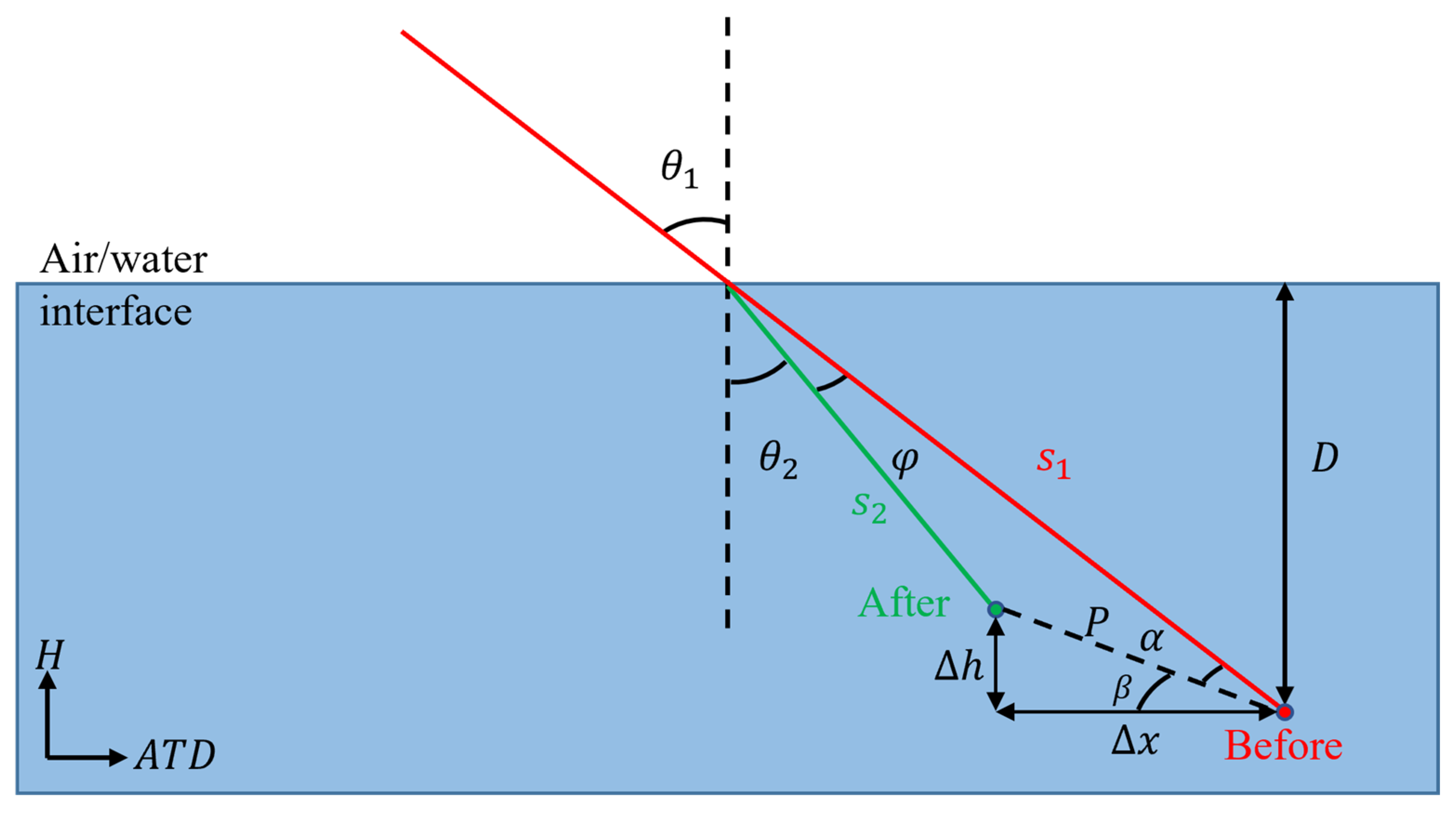
The elevation of seafloor photons has a systematic bias because the calculation of photon positions in the ATL03 dataset considers laser propagation in air; however, it neglects the refraction effect when light enters water and the inherent refractive index differences in water. Experimental studies have shown that this refraction effect can introduce elevation errors in the order of meters [39]. Therefore, for improved accuracy of SDB, correcting the refraction effect on seafloor photons is necessary. According to Snell’s law, when light passes through an interface between media with different refractive indices, its propagation direction and velocity change. Therefore, refraction correction needs to consider two aspects: correction of propagation direction and correction of propagation velocity. These two corrections effectively eliminate the impact of water refraction on photon positions, making them closer to the true values. Figure 2 illustrates the concept of refraction correction for photons.
First, correction is applied to the propagation direction. As shown in Figure 2, the red line represents the incident laser, the green line represents the refracted light, red dots represent photon positions before refraction correction, and green dots represent positions after correction. The ATL03 dataset provides the solar elevation angle refelev for each photon, allowing for the calculation of the angle of incidence θ1 using Equation (4):
θ 1 = π 2 r e f e l e v
The angle of refraction θ2 is then calculated according to the law of refraction θ2, as shown in Equation (5). In this study, the refractive index of air n1 is taken as 1.00029 and that of water n2 as 1.34116:
θ 2 = sin 1 n 1 sin θ 1 n 2
By computing the angle of incidence and angle of refraction, the new propagation direction of the light after refraction at the air–water interface can be determined. This is the first step in refraction correction, addressing the change in the direction of light upon entering the water and eliminating the influence of water refraction on photon positions.
Next, correction is applied to the propagation velocity. In Figure 2, S1 represents the path length of photons underwater without considering refraction effects, and S2 represents the path length of photons after considering refraction effects. The depth before refraction correction is defined as D. Therefore, S1 and S2 can be expressed using Equations (6) and (7), respectively:
S 1 = D cos θ 1
S 2 = S 1 n 1 n 2
Furthermore, the change in position P of photons before and after refraction correction can be calculated using the law of cosines, as shown in Equation (8):
P = S 2 2 + S 1 2 2 S 2 S 1 cos φ
Next, based on the law of sines, α can be calculated as shown in Equation (9):
α = sin 1 S 2 sin φ P
where φ = θ 1 θ 2 .
Ultimately, the changes in photon positions due to the refraction effect in the along-track and elevation directions can be represented as:
x = P cos β h = P sin β β = π 2 θ 1 α
Through the above calculations, corrections were applied to underwater photons to eliminate the effect of water refraction, yielding accurate photon positions.
In addition, as the sea surface changes with time and space, tidal correction needs to be applied to match the actual sea surface elevation and depth at the time of Sentinel-2 imaging. The water level difference Δl between the two moments was calculated using data from tide gauge stations near each study area because ICESat-2 photon data and Sentinel-2 imagery are acquired at different times. However, these deviations are negligible because the average water surface slope in each study area was only about 0.94°, and the horizontal and vertical deviations due to the water surface slope estimated using the method of Ma et al. [39] were less than a few centimeters. Therefore, the water depth of underwater photons at the time of Sentinel-2 imaging can be represented as:
D e p t h = D h + l
Refraction and tidal corrections are critical steps in satellite-driven ocean bathymetry. They directly impact the accuracy of SDB results. Through these two corrections, errors caused by different-medium refractions and dynamic tidal changes are eliminated, providing a foundation for building high-precision SDB models using ICESat-2 data.

2.6. Selection of Optical Deep-Water Areas and Sun Glint Correction

In the process of inverting water depths using the linear model, the selection of optical deep-water areas with distinct optical characteristics is crucial for improving SDB accuracy. Typically, two criteria are considered: first, opting for regions with a greater water depth to minimize the influence of seafloor reflections; second, choosing areas with relatively stable optical characteristics. For this purpose, Sentinel-2 imagery was overlaid with global 15-arcsecond grid ocean depth data to identify areas devoid of seafloor radiative energy. By overlaying the two datasets, identifying the elevation at the land–water interface or the shallowest depth, and recognizing areas where elevations are less than 100 m below this elevation, which can meet the first criterion for potential optical deep-water areas.
Due to sunlight contamination resulting from the geometric structure of Sentinel-2 satellite observations [41], optical deep-water area images often have sun glint, affecting the extraction of subsea energy in optical shallow-water areas. The presence of a prominent white “reflection” area and white bands near the wave edges in the selected deep-water areas indicates sample contamination by sun glint [54]. Correcting for sun glint in these optical deep-water areas to mitigate the increased surface radiative energy due to sunlight pollution is crucial. Therefore, sun glint correction was applied to the initially selected deep-water areas, stabilizing the optical characteristics of the imagery, which addresses the second criterion. In this study, the Hedley linear regression method was employed to correct sun glint in deep-water area images by scaling the near-infrared (NIR) band signal with a factor [54,55]:
R i V I S = R i V I S b i R N I R R m i n N I R
where bi is the slope of the linear regression line between the NIR band reflectance and visible band reflectance; R(NIR) is the reflectance in the NIR band; Rmin(NIR) is the minimum reflectance in the NIR band; and Ri(VIS) and Ri(VIS)′ are the reflectance in the visible band before and after correction, respectively.
Both of the above approaches aid in the selection of optimal optical deep-water areas, thereby enhancing the accuracy of the SDB model. Specifically, the introduction of global shallow-sea topographic data helps to technically identify potential deep-water areas with considerable water depths, while sun glint correction improves the stability of optical characteristics in deep-water-area images. These steps ensure that the selected optical deep-water areas possess sufficient water depth and stable optical scattering characteristics, laying the data foundation for establishing a quantitative relationship between subsea reflectance and water depth in optical shallow-water areas.

2.7. SDB Method Based on ICESat-2 Water Depth Data

Stumpf et al. [7] introduced the band ratio model by considering differences in water absorption rates across different spectral bands and applying linear and logarithmic transforms to these bands. Lyzenga [37,38] proposed a single-band SDB method, which was further extended to the linear model. Currently, the band ratio model and the linear model are the most widely applied empirical models. Studies have shown that the linear model generally outperforms the band ratio model in terms of SDB accuracy [39,56]. This is primarily because the linear model simplifies the radiative energy received by satellites into four components. By subtracting the radiative energy in deep-water areas, it removes other interfering energy components, thus establishing a more accurate correspondence between the subsea reflectance and water depth. This eventually improves the accuracy of SDB. The linear model is expressed as follows:
h w = a 0 + i = 1 k a i l n R W λ i R λ i
where hw is the water depth to be inverted; R w λ i is the radiative energy of the i band in remote sensing imagery; R λ i is the radiative energy of that band in optical deep-water areas; and a0 and ai are derived through linear regression, utilizing radiative energy from multi-spectral imagery at corresponding positions and prior water depths obtained from ICESat-2 data, as shown in Equation (14):
a i = i = 1 n x i y i n x ¯ y ¯ i = 1 n x i 2 n x ¯ 2 a 0 = y ¯ a i x ¯
where x i = R λ i R λ i ; yi is the prior water depth obtained from the ICESat-2 data; and x ¯ and y ¯ are the mean values of xi and yi, respectively.

2.8. Evaluation Metrics for SDB Results

The key metrics used to evaluate the accuracy of SDB water depth measurements include the coefficient of determination (R2), RMSE, and mean absolute error (MAE). R2 falls within the range of [0, 1], with larger values indicating better model fitting. Smaller RMSE values indicate reduced errors relative to true water depths, and smaller MAE values indicate lower discrepancies between estimated and actual water depths. R2, RMSE, and MAE can be calculated by Equations (15)–(17), respectively:
R 2 = 1 1 N Z Z 2 1 N Z ¯ Z 2
R M S E = 1 N Z Z 2 N
M A E = 1 N Z Z N
where Z′ is the estimated water depth; Z ¯ is the mean estimated water depth; Z is the true water depth; and N is the number of water depth photons.
In addition, linear regression was employed to assess the accuracy of SDB measurements. Taking the inverted water depth as the independent variable y and the true water depth as the dependent variable x, a straight-line fit of y = ax + b was performed. Here, a regression coefficient a approaching one indicated a linear correlation between the inverted and true water depths. A fit line closer to the y = x line implied smaller deviations between the inverted and true water depths, signifying higher accuracy in water depth estimation.

3. Results

3.1. ICESat-2 Bathymetric Points

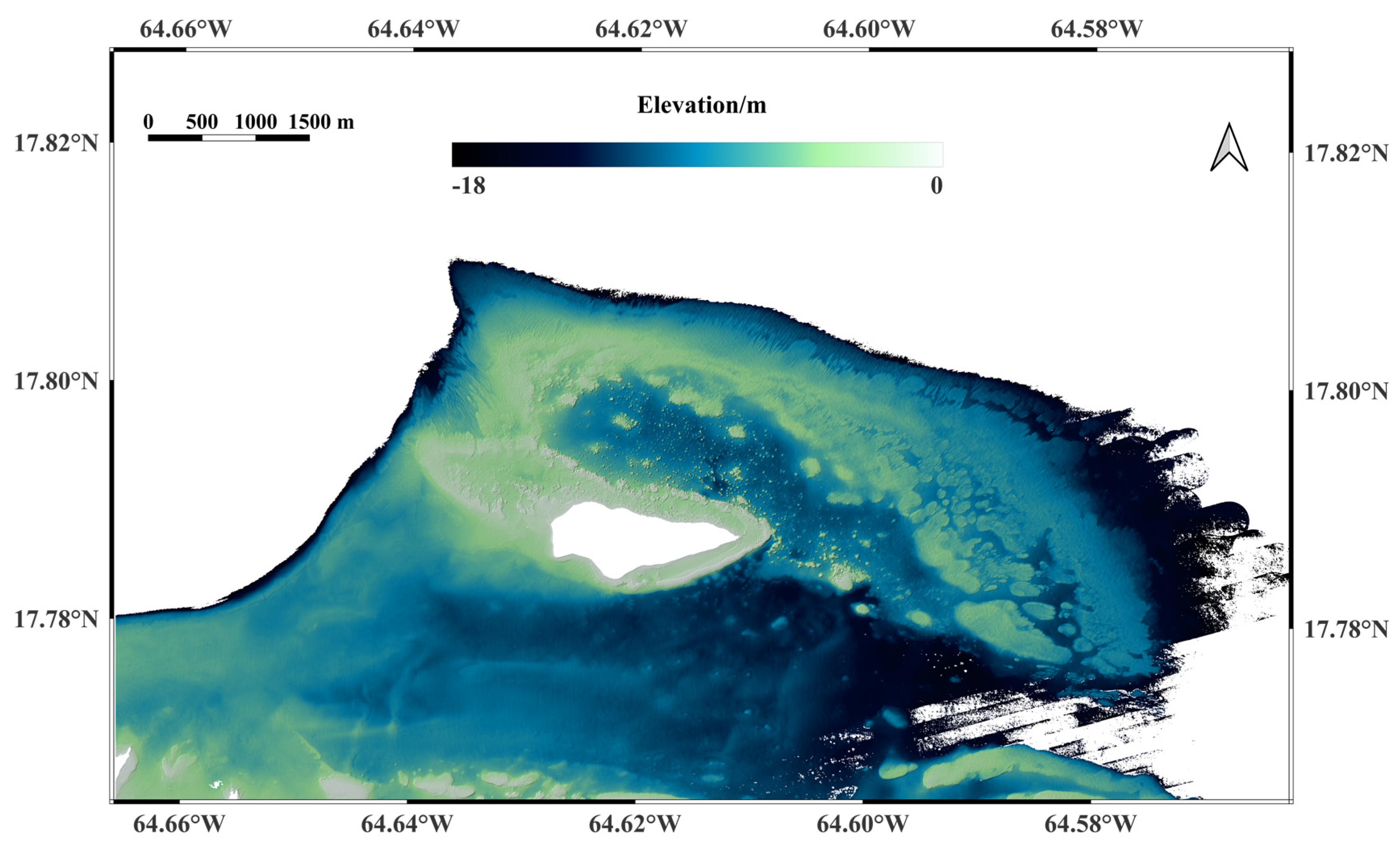
Seafloor photon signals were detected from the ICESat-2 ATL03 raw data set. The chosen study area for illustration covered by ICESat-2 satellite orbits and with a true DEM was the Buck Island region (Figure 3). In this region, six ICESat-2 beams passed through, with transit times as follows: 20191015GT1L, 20190105GT1R, and 20191015GT3R passed on 15 October 2019 at 02:22:08 (UTC); 20210314GT2R passed on 14 March 2021 at 01:44:56 (UTC); and 20210412GT1R and 20210412GT2R passed on 12 April 2021 at 00:21:00 (UTC). The methods described in Section 2.4 and 2.5 were used to detect seafloor photon signals and perform refraction correction. Figure 4 shows one of the signal photons of the beams before and after correction for 15 October 2019.
In Figure 4, the lidar photons have been converted from geographic latitude, longitude, and elevation in the along-track distance as well as along-track coordinate system. The x-axis represents the along-track distance of photons along the ICESat-2 flight path, while the y-axis represents the elevation of photons on the WGS84 ellipsoid. By calculating the elevation difference between the sea surface and seafloor photons, the ICESat-2 bathymetric results could be obtained. Therefore, the difference between the water level and DEM data at the time of satellite passage was calculated to obtain the true water depth at each beam’s passage time. Figure 5 compares the ICESat-2 bathymetric results with the true water depths.
Figure 5 evaluates the ICESat-2 bathymetric results from various beams, focusing on R2, RMSE, MAE, and regression line analysis. Notably, except for the marginally lower R2 values seen in Figure 5d,f, all other beams show R2 values exceeding 0.9, with the highest hitting an impressive 0.99. This underscores the strong linear correlation between the ICESat-2 bathymetric data and the corresponding in situ depth data, indicating high precision. Concerning RMSE, Figure 5a presents the lowest value at just 0.19 m, while Figure 5c,f show higher values of 0.71 m and 0.97 m, respectively. This variation is likely due to the deeper seafloor depths in these sub-areas, typically ranging from 12 to 18 m, where the ICESat-2 signals are weaker and more susceptible to noise. The MAE values exhibit similar trends, influenced by the same factors as the RMSE. Across all six beams, the average R2, RMSE, and MAE values are approximately 0.96, 0.15 m, and 0.20 m, respectively. As for the regression line coefficients, Figure 5d has a coefficient of 0.79, while the coefficients for the other five beams all exceed 0.9. Figure 5b stands out with a coefficient of one, reflecting an exceptionally strong correlation between the two data sets. These results collectively demonstrate a robust linear correlation and high precision between the ICESat-2 bathymetry data and in situ depth data.

3.2. Bathymetry of Different Optical Deep-Water Areas from the Same Image

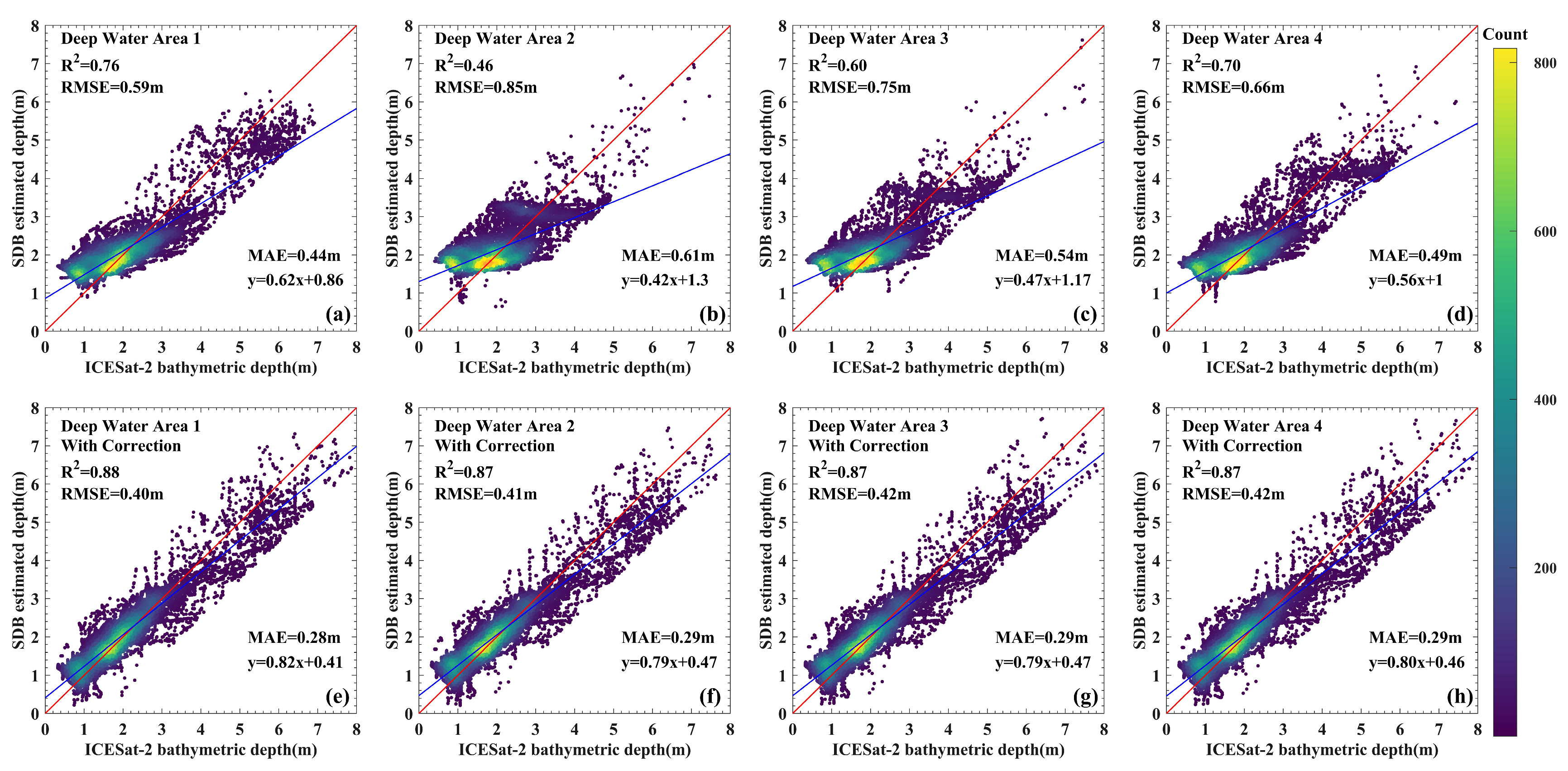
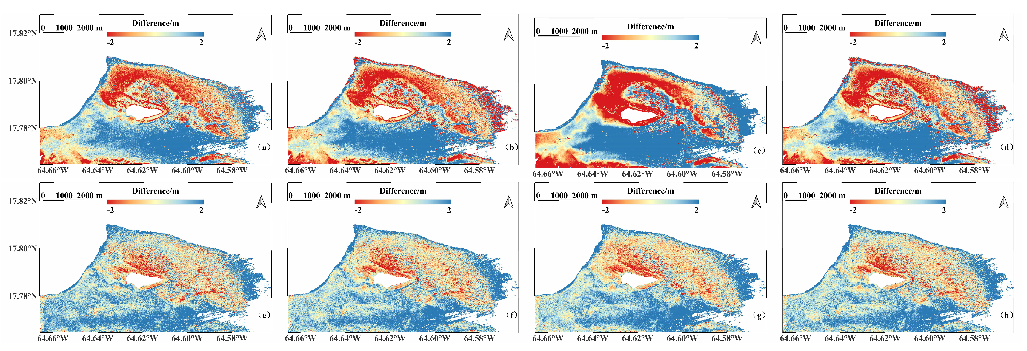
Three steps were followed to obtain water depth data for the two study areas. The bathymetric results from ICESat-2 were corrected to the acquisition time of remote sensing images, eliminating temporal errors. Secondly, global 15-arcsecond grid bathymetry data (https://www.gebco.net/data_and_products/gridded_bathymetry_data/, accessed on 20 December 2022) were used to identify the locations of deep-water areas, and corresponding optical deep-water area samples were identified on the remote sensing images. Finally, four deep-water area samples were randomly selected from the preprocessed Sentinel-2 images, and water depth results for the two study areas were obtained using the linear model (Figure 6, Figure 7, Figure 8 and Figure 9). Specifically, Figure 6a–d show the water depth maps obtained by training the model with four original deep-water area samples, while Figure 6e–h show the water depth maps obtained after sun glint correction.
Figure 6a–d reveals that although all four optical deep-water area samples are located in deep-water areas, the water depth results for the shallow areas surrounding Langhua Reef varied significantly when different samples were used. Specifically, Figure 6c,d produced relatively deep-water depths, while Figure 6a,b yielded relatively shallow water depths. Furthermore, all four results exhibited some degree of randomness. This preliminary finding demonstrated that the choice of optical deep-water area samples can influence the results of the SDB. However, after sun glint correction was applied to the four deep-water area samples, the water depth results shown in Figure 6e–h became more consistent. This suggests that even with different deep-water area samples, the use of sun glint correction can yield more stable SDB results. To assess the accuracy of the SDB results, 30% of the ICESat-2 water depth data, which were not involved in model training, were used as the ground truth and compared with the water depths obtained from the SDB (Figure 7).
When inverting water depth using original deep-water area samples, various accuracy metrics appeared to be random (Figure 7a–d). Specifically, R2 ranged from 0.46 to 0.76, RMSE varied between 0.59 and 0.85 m, MAE changed from 0.44 to 0.61 m, and the regression line coefficient fluctuated between 0.42 and 0.62. These values exhibited instability and lacked a clear pattern, confirming the earlier conclusion that “the choice of optical deep-water area samples can influence the results of the SDB”. Conversely, samples corrected for sun glint showed considerable improvements in all accuracy assessment metrics and greater stability. The R2 values were higher at approximately 0.88, 0.87, 0.87, and 0.87; the RMSE values decreased to approximately 0.40, 0.41, 0.42, and 0.42 m; the MAE values decreased to approximately 0.28, 0.29, 0.29, and 0.29 m; and the regression line coefficients increased to approximately 0.82, 0.79, 0.79, and 0.80. These results indicated that the use of optical deep-water area samples corrected for sun glint could markedly enhance the accuracy and robustness of the results.
The same method and steps were applied to obtain water depth results for the shallow-water areas around Buck Island. The differences between the inverted water depths and the true water depths obtained through DEM were solved, resulting in a water depth residual distribution (Figure 8).
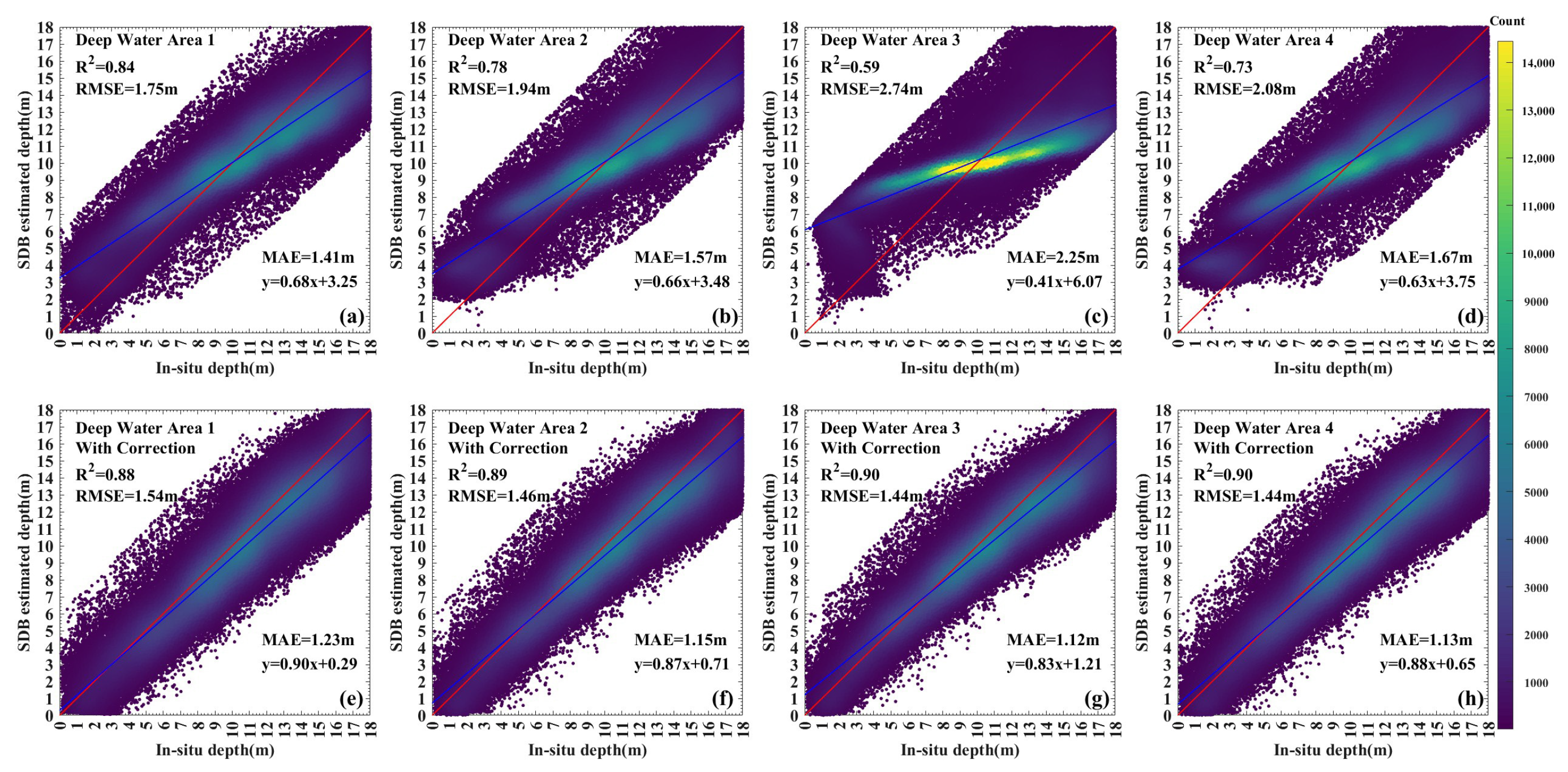
Among the results derived from original optical deep-water samples, the northern shallow water areas around Buck Island were mostly underestimated, while the southern areas were overestimated, with Figure 8c showing the largest errors and Figure 8a yielding relatively better results; nevertheless, with overall random variability (Figure 8a–d). Figure 8e–h illustrate the results based on samples corrected for sun glint, showing varying degrees of improvement in the errors in the underestimated northern areas and the overestimated southern areas. The four water-depth residual maps remained relatively stable. This indicated that the use of optical deep-water samples corrected for sun glint could significantly improve the accuracy and robustness of the SDB results in the nearshore areas of Buck Island. To quantitatively assess the impact of sun glint correction on the accuracy of the SDB for optical deep-water area samples, scatterplots of inverted water depth against true water depth were further generated (Figure 9).
When inverting water depth using original deep-water area samples, various accuracy metrics appeared random (Figure 9a–d). Specifically, R2 ranged from 0.59 to 0.84, RMSE varied between 1.75 and 2.74 m, MAE changed from 1.41 to 2.25 m, and the regression line coefficient fluctuated between 0.41 and 0.68. Figure 9e–h show that by using samples corrected for sun glint, accuracy metrics were noticeably improved and more stable. The R2 value increased to approximately 0.90, RMSE decreased to around 1.40 m, MAE declined to around 1.15 m, and the regression coefficient rose to approximately 0.90. A quantitative analysis demonstrated that using sun glint-corrected samples yielded higher correlation coefficients and lower errors. This is consistent with the conclusions drawn from the Langhua Reef case, reaffirming that the proposed method could enhance the accuracy and robustness of the SDB.

3.3. Bathymetry of the Same Optical Deep-Water Areas from Differently Dated Images

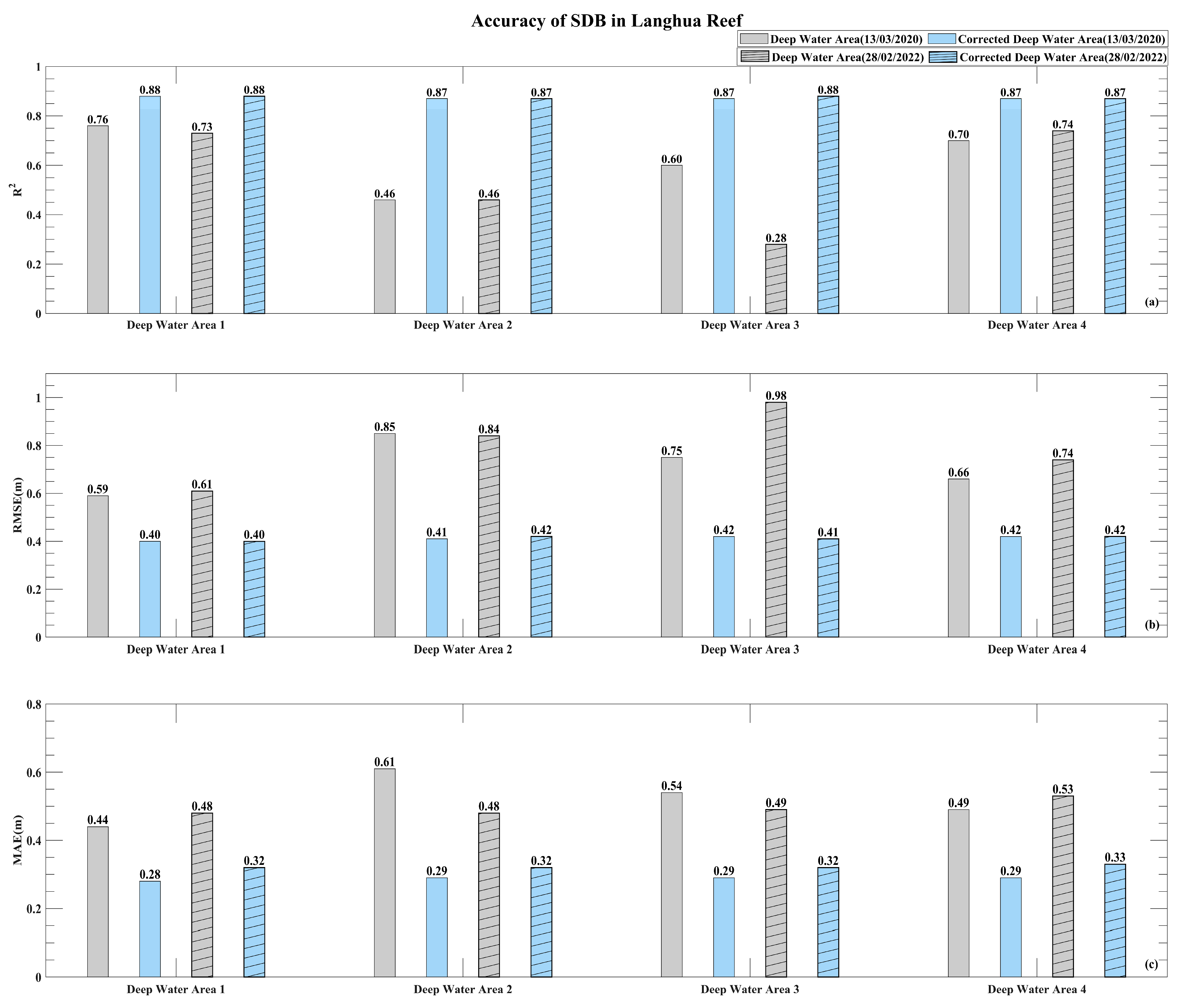
To assess the temporal scalability of the proposed method, Sentinel-2 images from 28 February 2022 for Langhua Reef and from 21 March 2019 for Buck Island were selected. The same processing workflow and optical deep-water area samples as those presented in Section 2.6 were applied, including sun glint correction and the use of the linear model for the SDB. Subsequently, the R2, RMSE, and MAE evaluation metrics for the same research areas from different time periods based on the same optical deep-water area samples were calculated. Figure 10 compares the accuracy metrics of the SDB results for Langhua Reef.
Figure 10a compares the R2 results of Langhua Reef from two different time periods, October 2020 and February 2022, using the same optical deep-water area samples in identical locations. The water depths inverted using the same optical deep-water area samples exhibited differences in R2 values between the two time periods, with the third sample area showing the greatest difference, dropping from 0.60 in 2020 to 0.28 in 2022. This difference arose from variations in sun glint on the water surface between different time periods, leading to inconsistent optical characteristics of the optical deep-water areas. However, after sun glint correction was applied separately to the eight samples from the two time periods, the R2 values for all eight results improved and became more consistent between the two time periods. This indicated that sun glint correction mitigated the impact of temporal changes in optical deep-water areas, stabilizing their optical characteristics and improving the consistency of the SDB results.
Figure 10b,c compare the RMSE and MAE values between the two time periods, respectively. Similar to R2, the third sample area exhibited relatively high RMSE and MAE values. After sun glint correction, the RMSE and MAE values for the inverted results from both time periods showed various degrees of improvement, enhancing overall consistency. For instance, the RMSE value decreased from the original range of 0.59–0.98 m to approximately 0.4 m, while the MAE value decreased from the original range of 0.44–0.61 m to approximately 0.3 m. Moreover, this confirmed that sun glint correction for optical deep-water areas reduces the influence of temporal changes and makes error metrics more consistent between different time periods. Figure 11 compares the accuracy metrics of the SDB results for Buck Island.
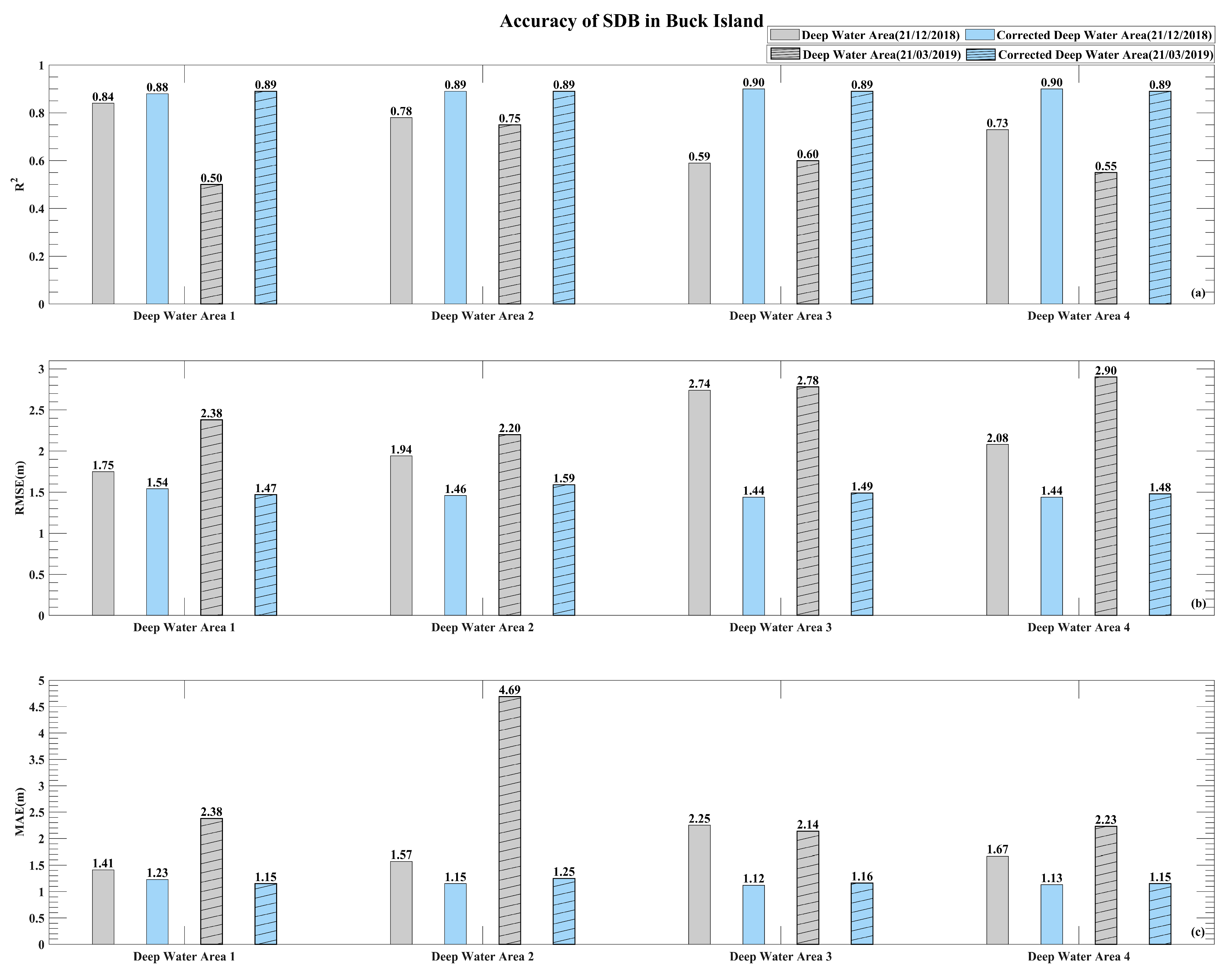
In the upper image, the accuracy metrics R2, RMSE, and MAE for the SDB results in different optical deep-water samples at different time phases on Buck Island are displayed. The findings align with those observed at Langhua Reef, revealing notable variations in the accuracy metrics when comparing the original samples from the two time phases. However, after sun glint correction in the optical deep-water areas, improvements in all metrics were observed for both time phases, and the temporal consistency was significantly enhanced compared to that of the original optical deep-water areas.
The results above indicate that original optical deep-water areas at the same location exhibit differences in SDB accuracy between different time phases due to variations in the impact of sun glint on the deep-water areas in an image. However, after sun glint correction, the accuracy metrics (R2, RMSE, and MAE) and temporal consistency of the SDB results improve. This demonstrates that sun glint correction for optical deep-water areas can mitigate the impact of temporal variations, leading to more accurate and stable SDB results.

4. Discussion

4.1. Availability of High-Confidence Photons in Water for the ATL03 Product

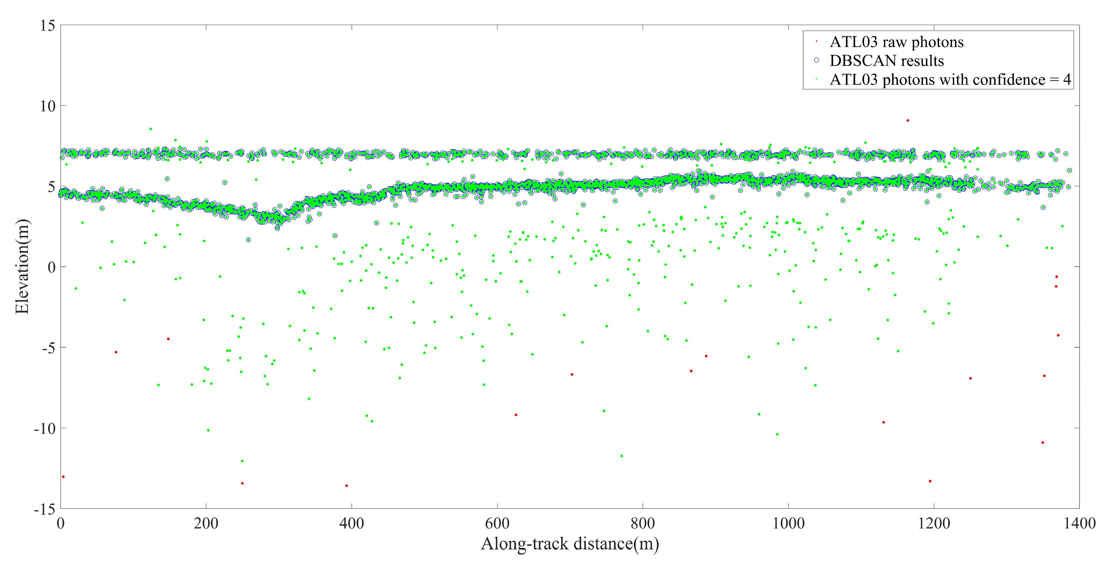
To assess the reliability of ICESat-2 photons, the ATL03 product provides a confidence parameter, with higher confidence values generally indicating useful echo signals. However, the confidence parameter of ICESat-2 photons in water environments is unreliable. Factors such as multiple scattering on the water surface, absorption and scattering by suspended matter, water absorption, surface wave disturbances, and the presence of biomass can alter the propagation path, intensity, and angles of photons, resulting in poor stability of photon confidence in the same water area. Moreover, complex interactions at the water-to-seafloor boundary may also change photon characteristics, reducing the accuracy of the confidence parameter. To further verify the instability of the confidence parameter, Langhua Reef was chosen for illustration.
The track contained distinct water surface and seafloor information (Figure 12). The algorithm accurately extracted water surface and seafloor photons, which should ideally have a confidence value of four, and treated them as true signals. In the ATL03 product, the confidence values for water surface and seafloor photons were set at four, effectively detecting complete track information of the water surface and seafloor topography. This indicated that the confidence parameter during the nighttime was relatively reliable. However, some identified noise photons were also assigned a confidence value of four under nighttime conditions. This could be attributed to the difficulty of distinguishing between noise photons and actual photons in the nighttime environment or biases introduced by the system’s own discriminations. Therefore, the nighttime confidence parameter in the ATL03 product was relatively trustworthy; however, careful consideration is required when using it in specific applications.
Compared to the nighttime environment, strong solar radiation during the day generates higher background noise, severely hindering the detection of weak-signal photons from ICESat-2 underwater. Confidence values of four were sparsely distributed on the water surface and seafloor in the ATL03 product of the daytime photon samples for Langhua Reef (Figure 13). This is distant from the water surface and seafloor photons that were identified. Therefore, during the daytime, the complex noise environments markedly affect the ability of the ATL03 product to distinguish the water surface and underwater photons, resulting in a high likelihood of missed detections. In contrast to the nighttime’s, the daytime ATL03 product photons with higher confidence levels represent fewer actual surface and seafloor signal photons, and their completeness is lower. Therefore, the complex noise environment must be considered when using the ATL03 product during the daytime to obtain prior depth information.

4.2. Equivalent Effect of Sun Glint Correction in Deep-Water Areas and Artificially Identifying Optimal Deep-Water Areas

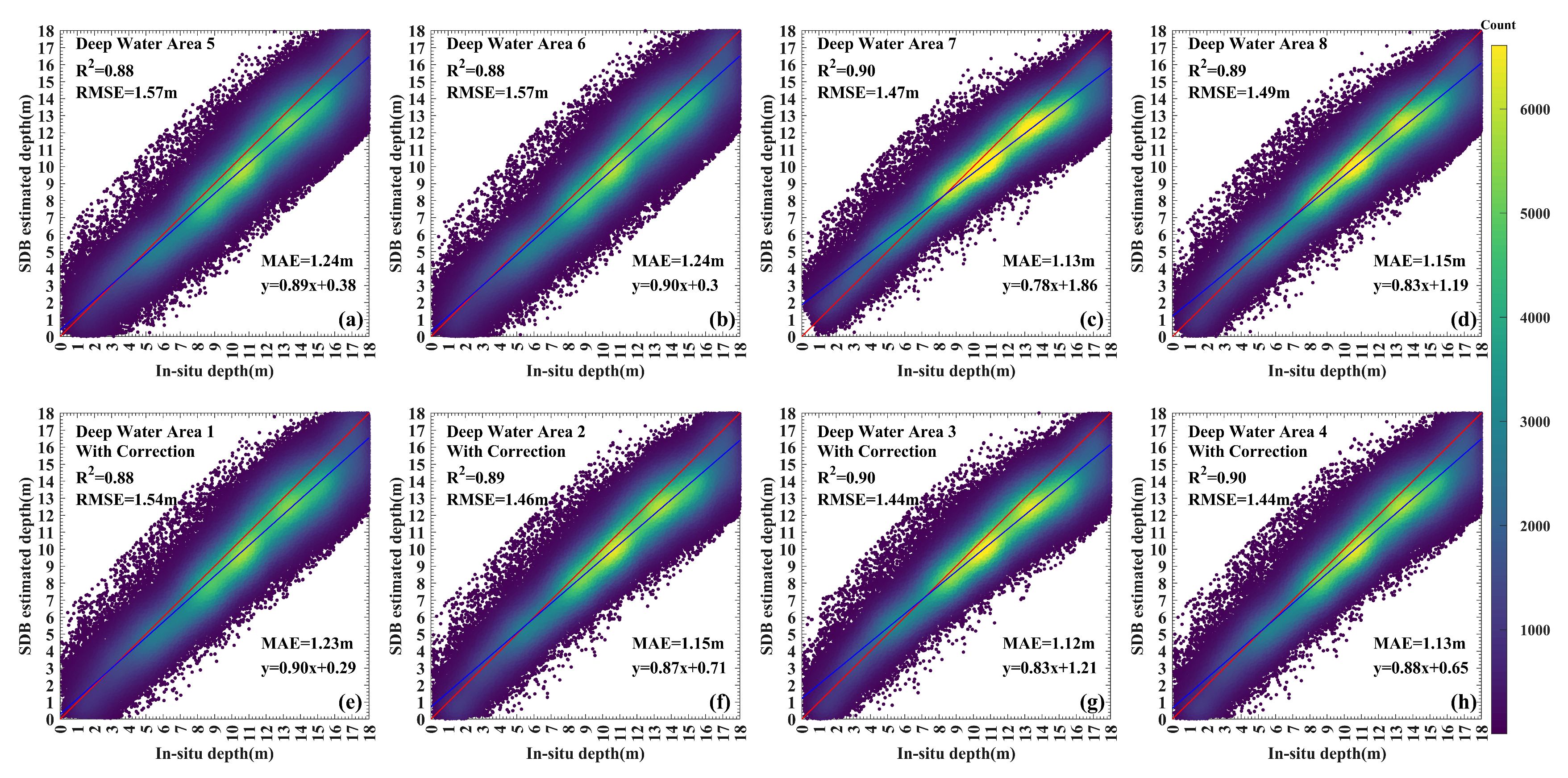
The accuracy of the SDB would be impacted by the selection of the deep-water areas. Although Hochberg et al. [55] provided empirical guidance for manually selecting deep-water areas with stable optical features, this method is time-consuming and relies on experience. If the proposed method could achieve results equivalent to manually identifying optimal samples, it could substantially improve the efficiency of SDB. To verify this hypothesis, the following experiment was designed: first, four optimal deep-water areas without sun glint were manually identified, and SDB was performed using these samples. Subsequently, deep-water areas, which underwent sun glint correction as described in Section 3.2, were also subjected to SDB. Finally, the accuracy metrics of the two SDB results were compared to assess whether the corrected areas could achieve equivalent or better results compared to manually identified deep-water areas. Using the Sentinel-2 image from Buck Island on 21 December 2018, a scatterplot of inverted depth against true depth was obtained (Figure 14).
Figure 14a–d present the precision assessment metrics for bathymetric analysis, employing a methodology centered on the manual identification of optimal deep-water areas. It is evident that each precision metric is relatively stable. Specifically, the R2 values range between 0.88 and 0.90, RMSE varies from 1.47 m to 1.57 m, MAE lies between 1.13 m and 1.24 m, and the regression line coefficients range from 0.78 to 0.90. Figure 14e–h demonstrate that after applying sun glint corrections to four random deep-water areas, not only is there a slight improvement in all precision assessment metrics, but also the stability among these metrics is maintained. Here, R2 ranges from 0.88 to 0.90, RMSE is between 1.44 m and 1.54 m, MAE spans 1.12 m to 1.23 m, and the regression line coefficients range from 0.83 to 0.90. These results confirm that applying sun glint corrections to any deep-water area can achieve equal or better outcomes than manually selecting the best deep-water areas. This finding holds significant implications for practical scenarios where optimal samples are unobtainable, suggesting that sun glint corrections to existing deep-water areas can optimize the data quality of optical deep-water regions, thereby substantially enhancing the accuracy and robustness of shallow water depth inversion based on multi-band combination models in satellite imagery.
The importance of this discovery is far-reaching, particularly in practical situations where obtaining optimal deep-water areas is not feasible. Its implications are significant, suggesting that optical deep-water areas can be effectively optimized through sun glint correction. This enhancement leads to a marked improvement in the precision and overall robustness of SDB. This insight not only advances our understanding of SDB accuracy but also offers a viable approach for enhancing the reliability of SDB in scenarios where manual optimal sampling is challenging.

5. Conclusions

In this study, shallow water depth data obtained from the spaceborne lidar on ICESat-2 were used to replace in situ depth data, and the linear model was trained to investigate the impact of optical deep-water areas on the SDB. Considering the importance of selecting optical deep-water areas for model training, this study proposed a method to identify and process deep-water areas: combining satellite images with global shallow-water topographic data to identify potential deep-water areas and performing sun glint correction on potential deep-water areas to reduce the impact of sunlight on the reflectance bands and improve the stability of the optical characteristics of deep-water areas. To validate the effectiveness of the proposed method, experiments were conducted in two study areas, i.e., Langhua Reef in the South China Sea and Buck Island in the U.S. Virgin Islands.
When training the model using four randomly selected optical deep-water areas from the same image, the statistical indicators, such as R2, RMSE, MAE, and regression line coefficient for both study areas, Langhua Reef and Buck Island, exhibited unstable randomness due to random factors, such as sun glint. After sun glint correction, these indicators improved significantly. For Langhua Reef, the R2 value increased from approximately 0.46–0.76 to around 0.88, the RMSE value decreased from approximately 0.59–0.85 m to around 0.40 m, the MAE value decreased from approximately 0.44–0.61 m to around 0.29 m, and the regression line coefficient increased from approximately 0.42–0.62 to around 0.80. For Buck Island, the R2 value increased from approximately 0.59–0.84 to around 0.90, the RMSE value decreased from approximately 1.75–2.74 m to around 1.40 m, the MAE value decreased from approximately 1.41–2.25 m to around 1.15 m, and the regression line coefficient increased from approximately 0.42–0.62 to around 0.90. In addition, comparing the SDB results from images taken at different times in 2020 and 2022, temporal inconsistency was observed when using the original optical deep-water areas for SDB. However, the consistency of samples improved after sun glint correction. For example, at the same location in Langhua Reef, the SDB results from optical deep-water areas in images from 2020 and 2022 showed significant inconsistency, with the R2 value fluctuating between 0.50 and 0.84, the RMSE value between 1.75 and 2.78 m, and the MAE value between 1.41 and 4.69 m. After sun glint correction, the R2 value increased to around 0.89, the RMSE value decreased to around 1.50 m, and the MAE value decreased to around 1.15 m. The accuracy metrics and temporal consistency of the SDB results for this study area were significantly improved. Similar conclusions were obtained for the Buck Island area.
While the method demonstrated here shows promising results, it is crucial to recognize its limitations. The approach used in this research relies on the linear model that requires the selection of deep-water areas. Implementing the specific techniques described in the study improves the accuracy and robustness of SDB. However, additional research is needed to assess the applicability of this methodology with other SDB models, which calls for further discussion.
This study primarily concentrates on the optical shallow waters of Case-1 water bodies. It is essential to recognize that the effectiveness of the proposed method in river bathymetry could be influenced by the challenges arising from variations in water quality and clarity, which are typical in riverine environments. The limited width and depth of rivers often makes it difficult to find optical deep-water areas. Therefore, additional investigations and a validation of this method in riverine contexts are necessary to evaluate its reliability under varied conditions.
The results indicated that the proposed method for selecting optical deep-water areas and correcting sun glint in deep-water areas could significantly improve the quality of the SDB results. This represents an advancement in the field of optical shallow-water bathymetry, especially in situations where identifying optimal optical deep-water areas is challenging.

Author Contributions

Conceptualization, D.J., Y.L. and X.H.; methodology, Y.L., D.J. and Z.Y.; software, Y.L. and T.W.; validation, Y.L. and Y.W.; formal analysis, D.J. and T.W.; investigation, Y.L. and N.X.; resources, D.J., X.H. and Z.Y.; data curation, Y.L.; writing—original draft preparation, D.J. and Y.L.; writing—review and editing, D.J., Y.L., Y.W. and N.X.; visualization, Y.L.; supervision, D.J., X.H. and Z.Y.; project administration, D.J.; funding acquisition, D.J. and Y.W. All authors have read and agreed to the published version of the manuscript.

Funding

This research was funded by the National Natural Science Foundation of China, grant numbers 41474001, 41830110, 42374099 and 42004008; the China Railway Corporation, grant numbers 2021-key-14 and 2021-major-08; the Surveying and Mapping Basic Research Program of the National Administration of Surveying, Mapping, and Geoinformation, grant number 13-01-05.

Data Availability Statement

Data are contained within the article.

Acknowledgments

We wish to extend our sincere gratitude to the organizations and sources that facilitated our research. We acknowledge the NASA National Snow and Ice Data Center (NSIDC) for granting us access to the ICESat-2 data and the European Space Agency (ESA) for providing access to Sentinel-2 imagery, both of which played a pivotal role in our study. Additionally, we appreciate the support from the National Oceanic and Atmospheric Administration (NOAA) for sharing the Digital Elevation Model (DEM) and water level data. Special thanks go to https://www.chaoxibiao.net/ (accessed on 10 December 2022) for their valuable contribution of water level data. We are also grateful to The General Bathymetric Chart of the Oceans (GEBCO) for their generous provision of gridded bathymetry data.

Conflicts of Interest

The authors declare no conflict of interest.

References

  1. Kutser, T.; Hedley, J.; Giardino, C.; Roelfsema, C.; Brando, V.E. Remote sensing of shallow waters—A 50 year retrospective and future directions. Remote Sens. Environ. 2020, 240, 111619. [Google Scholar] [CrossRef]
  2. Lubin, D.; Li, W.; Dustan, P.; Mazel, C.H.; Stamnes, K. Spectral Signatures of Coral Reefs: Features from Space. Remote Sens. Environ. 2001, 75, 127–137. [Google Scholar] [CrossRef]
  3. McCarthy, M.J.; Otis, D.B.; Hughes, D.; Muller-Karger, F.E. Automated high-resolution satellite-derived coastal bathymetry mapping. Int. J. Appl. Earth Obs. Geoinf. 2022, 107, 102693. [Google Scholar] [CrossRef]
  4. Bandini, F.; Kooij, L.; Mortensen, B.K.; Caspersen, M.B.; Thomsen, L.G.; Olesen, D.; Bauer-Gottwein, P. Mapping inland water bathymetry with Ground Penetrating Radar (GPR) on board Unmanned Aerial Systems (UASs). J. Hydrol. 2023, 616, 128789. [Google Scholar] [CrossRef]
  5. Costa, B.M.; Battista, T.A.; Pittman, S.J. Comparative evaluation of airborne LiDAR and ship-based multibeam SoNAR bathymetry and intensity for mapping coral reef ecosystems. Remote Sens. Environ. 2009, 113, 1082–1100. [Google Scholar] [CrossRef]
  6. Wang, C.-K.; Philpot, W.D. Using airborne bathymetric lidar to detect bottom type variation in shallow waters. Remote Sens. Environ. 2007, 106, 123–135. [Google Scholar] [CrossRef]
  7. Stumpf, R.P.; Holderied, K.; Sinclair, M. Determination of water depth with high-resolution satellite imagery over variable bottom types. Limnol. Oceanogr. 2003, 48, 547–556. [Google Scholar] [CrossRef]
  8. Mumby, P.J.; Green, E.P.; Edwards, A.J.; Clark, C.D. Measurement of seagrass standing crop using satellite and digital airborne remote sensing. Oceanogr. Lit. Rev. 1998, 45, 1069. [Google Scholar] [CrossRef]
  9. Kutser, T.; Miller, I.; Jupp, D.L.B. Mapping coral reef benthic substrates using hyperspectral space-borne images and spectral libraries. Estuar. Coast. Shelf Sci. 2006, 70, 449–460. [Google Scholar] [CrossRef]
  10. Olmanson, L.G.; Bauer, M.E.; Brezonik, P.L. A 20-year Landsat water clarity census of Minnesota’s 10,000 lakes. Remote Sens. Environ. 2008, 112, 4086–4097. [Google Scholar] [CrossRef]
  11. Kovacs, E.; Roelfsema, C.; Lyons, M.; Zhao, S.; Phinn, S. Seagrass habitat mapping: How do Landsat 8 OLI, Sentinel-2, ZY-3A, and Worldview-3 perform? Remote Sens. Lett. 2018, 9, 686–695. [Google Scholar] [CrossRef]
  12. Adler-Golden, S.M.; Acharya, P.K.; Berk, A.; Matthew, M.W.; Gorodetzky, D. Remote bathymetry of the littoral zone from AVIRIS, LASH, and QuickBird imagery. IEEE Trans. Geosci. Remote Sens. 2005, 43, 337–347. [Google Scholar] [CrossRef]
  13. Albert, A.; Gege, P. Inversion of irradiance and remote sensing reflectance in shallow water between 400 and 800 nm for calculations of water and bottom properties. Appl. Opt. 2006, 45, 2331–2343. [Google Scholar] [CrossRef] [PubMed]
  14. Lee, Z.; Carder, K.L.; Chen, R.F.; Peacock, T.G. Properties of the water column and bottom derived from Airborne Visible Infrared Imaging Spectrometer (AVIRIS) data. J. Geophys. Res. Ocean. 2001, 106, 11639–11651. [Google Scholar] [CrossRef]
  15. Brando, V.E.; Anstee, J.M.; Wettle, M.; Dekker, A.G.; Phinn, S.R.; Roelfsema, C. A physics based retrieval and quality assessment of bathymetry from suboptimal hyperspectral data. Remote Sens. Environ. 2009, 113, 755–770. [Google Scholar] [CrossRef]
  16. Benny, A.H.; Dawson, G.J. Satellite Imagery as an Aid to Bathymetric Charting in the Red Sea. Cartogr. J. 2013, 20, 5–16. [Google Scholar] [CrossRef]
  17. Weidmark, W.C.; Jain, S.C.; Zwick, H.H.; Miller, J.R. Passive bathymetric measurements in the Bruce Peninsula region of Ontario. In Proceeding of the 15th International Symposium on Remote Sensing of Environment, Ann Arbor, MI, USA, 11–15 May 1981; pp. 811–822. [Google Scholar]
  18. Lyzenga, D. Shallow-Water Reflectance Modeling with Applications to Remote Sensing of the Ocean Floor. In Proceeding of the 13th International Symposium on Remote Sensing of Environment, Ann Arbor, MI, USA, 23–27 April 1979; Volume 1, pp. 583–602. [Google Scholar]
  19. Lee, Z.; Carder, K.L.; Mobley, C.D.; Steward, R.G.; Patch, J.S. Hyperspectral remote sensing for shallow waters. I. A semianalytical model. Appl. Opt. 1998, 37, 6329–6338. [Google Scholar] [CrossRef]
  20. Chaoyu, Y.; Dingtian, Y. Improved method to analyze hyperspectral characteristics of coral reefs. Chin. Opt. Lett. 2014, 12, S21001. [Google Scholar] [CrossRef]
  21. Jay, S.; Guillaume, M. Regularized estimation of bathymetry and water quality using hyperspectral remote sensing. Int. J. Remote Sens. 2016, 37, 263–289. [Google Scholar] [CrossRef]
  22. Liu, Z.; Hu, L.; He, M.-X. Simulation of shallow water depth data merging for HJ-1A/HSI and EO-1/Hyperion. In Proceedings of the 2014 IEEE Geoscience and Remote Sensing Symposium, Quebec City, QC, Canada, 13–18 July 2014; pp. 2957–2960. [Google Scholar]
  23. Gülher, E.; Alganci, U. Satellite-Derived Bathymetry Mapping on Horseshoe Island, Antarctic Peninsula, with Open-Source Satellite Images: Evaluation of Atmospheric Correction Methods and Empirical Models. Remote Sens. 2023, 15, 2568. [Google Scholar] [CrossRef]
  24. Flener, C.; Lotsari, E.; Alho, P.; Käyhkö, J. Comparison of empirical and theoretical remote sensing based bathymetry models in river environments. River Res. Appl. 2012, 28, 118–133. [Google Scholar] [CrossRef]
  25. Ceyhun, Ö.; Yalçın, A. Remote sensing of water depths in shallow waters via artificial neural networks. Estuar. Coast. Shelf Sci. 2010, 89, 89–96. [Google Scholar] [CrossRef]
  26. Sagawa, T.; Yamashita, Y.; Okumura, T.; Yamanokuchi, T. Satellite Derived Bathymetry Using Machine Learning and Multi-Temporal Satellite Images. Remote Sens. 2019, 11, 1155. [Google Scholar] [CrossRef]
  27. Bué, I.; Catalão, J.; Semedo, Á. Intertidal Bathymetry Extraction with Multispectral Images: A Logistic Regression Approach. Remote Sens. 2020, 12, 1311. [Google Scholar] [CrossRef]
  28. Prasetya, M.I.; Siregar, V.P.; Agus, S.B. Comparison of Satellite-Derived Bathymetry Algorithm Accuracy Using Sentinel-2 Multispectral Satellite Image. J. Kelaut. Trop. 2023, 26, 113–125. [Google Scholar] [CrossRef]
  29. Rahman, A. Depth Estimation of Shallow Water Using Multispectral Satellite Imagery Sentinel-2a. J. Segara 2020, 16. [Google Scholar] [CrossRef]
  30. Wang, L.; Liu, H.X.; Su, H.B.; Wang, J. Bathymetry retrieval from optical images with spatially distributed support vector machines. Giscience Remote Sens. 2019, 56, 323–337. [Google Scholar] [CrossRef]
  31. Misra, A.; Vojinovic, Z.; Ramakrishnan, B.; Luijendijk, A.; Ranasinghe, R. Shallow water bathymetry mapping using Support Vector Machine (SVM) technique and multispectral imagery. Int. J. Remote Sens. 2018, 39, 4431–4450. [Google Scholar] [CrossRef]
  32. Zhou, W.; Tang, Y.; Jing, W.; Li, Y.; Yang, J.; Deng, Y.; Zhang, Y. A Comparison of Machine Learning and Empirical Approaches for Deriving Bathymetry from Multispectral Imagery. Remote Sens. 2023, 15, 393. [Google Scholar] [CrossRef]
  33. Lyzenga, D.R. Remote sensing of bottom reflectance and water attenuation parameters in shallow water using aircraft and Landsat data. Int. J. Remote Sens. 2010, 2, 71–82. [Google Scholar] [CrossRef]
  34. Philpot, W.D. Bathymetric mapping with passive multispectral imagery. Appl. Opt. 1989, 28, 1569–1578. [Google Scholar] [CrossRef] [PubMed]
  35. Huang, Y.; Yang, H.; Tang, S.; Liu, Y.; Liu, Y. An Appraisal of Atmospheric Correction and Inversion Algorithms for Mapping High-Resolution Bathymetry Over Coral Reef Waters. IEEE Trans. Geosci. Remote Sens. 2023, 61, 4204511. [Google Scholar] [CrossRef]
  36. Xu, Y.; Cao, B.; Deng, R.; Cao, B.; Liu, H.; Li, J. Bathymetry over broad geographic areas using optical high-spatial-resolution satellite remote sensing without in-situ data. Int. J. Appl. Earth Obs. Geoinf. 2023, 119, 103308. [Google Scholar] [CrossRef]
  37. Lyzenga, D.R. Shallow-water bathymetry using combined lidar and passive multispectral scanner data. Int. J. Remote Sens. 2010, 6, 115–125. [Google Scholar] [CrossRef]
  38. Lyzenga, D.R.; Malinas, N.P.; Tanis, F.J. Multispectral bathymetry using a simple physically based algorithm. IEEE Trans. Geosci. Remote Sens. 2006, 44, 2251–2259. [Google Scholar] [CrossRef]
  39. Ma, Y.; Xu, N.; Liu, Z.; Yang, B.; Yang, F.; Wang, X.H.; Li, S. Satellite-derived bathymetry using the ICESat-2 lidar and Sentinel-2 imagery datasets. Remote Sens. Environ. 2020, 250, 112047. [Google Scholar] [CrossRef]
  40. Westley, K. Satellite-derived bathymetry for maritime archaeology: Testing its effectiveness at two ancient harbours in the Eastern Mediterranean. J. Archaeol. Sci. Rep. 2021, 38, 103030. [Google Scholar] [CrossRef]
  41. Harmel, T.; Chami, M.; Tormos, T.; Reynaud, N.; Danis, P.-A. Sunglint correction of the Multi-Spectral Instrument (MSI)-SENTINEL-2 imagery over inland and sea waters from SWIR bands. Remote Sens. Environ. 2018, 204, 308–321. [Google Scholar] [CrossRef]
  42. Su, H.; Liu, H.; Heyman, W.D. Automated Derivation of Bathymetric Information from Multi-Spectral Satellite Imagery Using a Non-Linear Inversion Model. Mar. Geod. 2008, 31, 281–298. [Google Scholar] [CrossRef]
  43. Mishra, D.; Narumalani, S.; Rundquist, D.; Lawson, M. Benthic Habitat Mapping in Tropical Marine Environments Using QuickBird Multispectral Data. Photogramm. Eng. Remote Sens. 2006, 72, 1037–1048. [Google Scholar] [CrossRef]
  44. Caballero, I.; Stumpf, R.P. Atmospheric correction for satellite-derived bathymetry in the Caribbean waters: From a single image to multi-temporal approaches using Sentinel-2A/B. Opt. Express 2020, 28, 11742–11766. [Google Scholar] [CrossRef] [PubMed]
  45. Duan, Z.; Chu, S.; Cheng, L.; Ji, C.; Li, M.; Shen, W. Satellite-derived bathymetry using Landsat-8 and Sentinel-2A images: Assessment of atmospheric correction algorithms and depth derivation models in shallow waters. Opt. Express 2022, 30, 3238–3261. [Google Scholar] [CrossRef] [PubMed]
  46. Pacheco, A.; Horta, J.; Loureiro, C.; Ferreira, Ó. Retrieval of nearshore bathymetry from Landsat 8 images: A tool for coastal monitoring in shallow waters. Remote Sens. Environ. 2015, 159, 102–116. [Google Scholar] [CrossRef]
  47. Xu, N.; Ma, X.; Ma, Y.; Zhao, P.; Yang, J.; Wang, X.H. Deriving Highly Accurate Shallow Water Bathymetry From Sentinel-2 and ICESat-2 Datasets by a Multitemporal Stacking Method. IEEE J. Sel. Top. Appl. Earth Obs. Remote Sens. 2021, 14, 6677–6685. [Google Scholar] [CrossRef]
  48. Chu, S.; Cheng, L.; Ruan, X.; Zhuang, Q.; Zhou, X.; Li, M.; Shi, Y. Technical framework for shallow-water bathymetry with high reliability and no missing data based on time-series sentinel-2 images. IEEE Trans. Geosci. Remote Sens. 2019, 57, 8745–8763. [Google Scholar] [CrossRef]
  49. Abdul Gafoor, F.; Al-Shehhi, M.R.; Cho, C.-S.; Ghedira, H. Gradient Boosting and Linear Regression for Estimating Coastal Bathymetry Based on Sentinel-2 Images. Remote Sens. 2022, 14, 5037. [Google Scholar] [CrossRef]
  50. Xu, H. Modification of normalised difference water index (NDWI) to enhance open water features in remotely sensed imagery. Int. J. Remote Sens. 2007, 27, 3025–3033. [Google Scholar] [CrossRef]
  51. Neumann, T.A.; Martino, A.J.; Markus, T.; Bae, S.; Bock, M.R.; Brenner, A.C.; Brunt, K.M.; Cavanaugh, J.; Fernandes, S.T.; Hancock, D.W.; et al. The Ice, Cloud, and Land Elevation Satellite-2 Mission: A Global Geolocated Photon Product Derived from the Advanced Topographic Laser Altimeter System. Remote Sens. Environ. 2019, 233, 111325. [Google Scholar] [CrossRef]
  52. Jasinski, M.F.; Stoll, J.D.; Cook, W.B.; Ondrusek, M.; Stengel, E.; Brunt, K. Inland and Near Shore Water Profiles Derived from the High Altitude Multiple Altimeter Beam Experimental Lidar (MABEL). J. Coast. Res. 2016, 76, 44–55. [Google Scholar] [CrossRef]
  53. Xu, N.; Ma, Y.; Yang, J.; Wang, X.H.; Wang, Y.; Xu, R. Deriving Tidal Flat Topography Using ICESat-2 Laser Altimetry and Sentinel-2 Imagery. Geophys. Res. Lett. 2022, 49, e2021GL096813. [Google Scholar] [CrossRef]
  54. Hedley, J.D.; Harborne, A.R.; Mumby, P.J. Technical note: Simple and robust removal of sun glint for mapping shallow-water benthos. Int. J. Remote Sens. 2007, 26, 2107–2112. [Google Scholar] [CrossRef]
  55. Hochberg, E.J.; Andrefouet, S.; Tyler, M.R. Sea surface correction of high spatial resolution ikonos images to improve bottom mapping in near-shore environments. IEEE Trans. Geosci. Remote Sens. 2003, 41, 1724–1729. [Google Scholar] [CrossRef]
  56. Thomas, N.; Pertiwi, A.P.; Traganos, D.; Lagomasino, D.; Poursanidis, D.; Moreno, S.; Fatoyinbo, L. Space-Borne Cloud-Native Satellite-Derived Bathymetry (SDB) Models Using ICESat-2 And Sentinel-2. Geophys. Res. Lett. 2021, 48, e2020GL092170. [Google Scholar] [CrossRef]
Figure 1. (a) The Langhua Reef located in the South China Sea shown in two Sentinel-2 images acquired on 10 March 2020 and 28 February 2022. The blue, green, red, and yellow lines represent ICESat-2 data acquired on 18 October 2018; 15 January 2020; 12 September 2021; and 12 December 2021. (b) Buck Island, located near the U.S. Virgin Islands, is shown in two Sentinel-2 images acquired on 21 December 2018 and 21 March 2019. The blue, green, and red lines represent ICESat-2 data acquired on 15 October 2019; 14 March 2021; and 12 April 2021.
Remotesensing 15 05406 g001
Figure 2. Schematic diagram of refraction correction for photons.
Remotesensing 15 05406 g002
Figure 3. DEM data of the seafloor near the Buck Island study area.
Remotesensing 15 05406 g003
Figure 4. Photon refraction-corrected map of ICESat-2 for 20191015GT1L in Buck Island, with data collection on 15 October 2019 at 02:22:08 (UTC). The blue dots in the plot are surface photon data, the red dots are underwater terrain photon data before refraction correction, and the green dots are underwater terrain photon data after refraction correction.
Remotesensing 15 05406 g004
Figure 5. Comparison of ICESat-2 bathymetry results with true bathymetry results in Buck Island, where the red line is the 1:1 line and the blue line is the regression line. (af) are the results of beams 20191015GT1L, 20190105GT1R, 20191015GT3R, 20210314GT2R, 20210412GT1R, and 20210412GT2R, respectively. With lighter colors indicating a higher count of points in this position.
Remotesensing 15 05406 g005
Figure 6. Bathymetric maps of the area around Langhua Reef obtained using 10 March 2020 Sentinel-2 imagery and 70% ICESat-2 bathymetric data. (ad) Bathymetric maps obtained using the four original deep-water areas. (eh) Bathymetric maps obtained from samples corrected for solar flares.
Remotesensing 15 05406 g006
Figure 7. Scatterplot of bathymetric error using 10 March 2020 image inversion of Langhua Reef bathymetry with 30% ICESat-2. (ad) Scatterplots of the derived bathymetric error using four different deep-water areas involved in model training. (eh) Scatterplots of bathymetric errors after solar flare correction for the four deep-water areas. With lighter colors indicating a higher count of points in this position.
Remotesensing 15 05406 g007
Figure 8. Bathymetric maps of Buck Island derived from the model using images from 21 December 2018. (ad) Bathymetric maps derived from model training using four different deep-water areas. (eh) Bathymetric maps derived after solar flare correction for four deep-water areas.
Remotesensing 15 05406 g008
Figure 9. Scatterplot of bathymetric error using 21 December 2018 imagery inversion of Buck Island bathymetry with in situ depth. (ad) Scatterplots of the derived bathymetric error using four different deep-water areas involved in model training. (eh) Scatterplots of the bathymetric error after solar flare correction for the four deep-water areas. With lighter colors indicating a higher count of points in this position.
Remotesensing 15 05406 g009
Figure 10. Accuracy metrics of water depth maps derived through model training using four different deep-water areas chosen from two separate remote sensing images of Langhua Reef. Subfigures (ac) depict the comparisons for R2, RMSE, and MAE, respectively.
Remotesensing 15 05406 g010
Figure 11. Accuracy metrics of water depth maps derived through model training using four different deep-water areas chosen from two separate remote sensing images of Buck Island. Subfigures (ac) depict the comparisons for R2, RMSE, and MAE, respectively.
Remotesensing 15 05406 g011
Figure 12. The along-track profile of Langhua Reef photons recorded by the ATL03 product, with ICESat-2 passing through the local area at 01:26:31 on 15 August 2019. The red dots represent the raw data from the ATL03 product, the green dots are the raw data with a confidence level of 4, and the blue hollow circles are the signal photons identified by the DBSCAN clustering algorithm.
Remotesensing 15 05406 g012
Figure 13. Along-track profile of Langhua Reef photons recorded by the ATL03 product with ICESat-2 passing through the local area at 09:57:32 on 15 March 2021. The red dots represent the raw data from the ATL03 product, the green dots are the raw data with a confidence level of four, and the blue hollow circles are the signal photons identified by the DBSCAN clustering algorithm.
Remotesensing 15 05406 g013
Figure 14. Scatterplot of bathymetry error in inverted Buck Island bathymetry versus in situ bathymetry using images from 21 December 2018. (ad) Scatterplots of bathymetry error obtained by manually identifying the optimal deep-water samples. (eh) Scatterplots of bathymetry error obtained after randomly selecting four deep-water zones and correcting for solar flares.
Remotesensing 15 05406 g014
Table 1. Information on the study areas and the Sentinel-2 and ICESat-2 datasets.
Study AreaLanghua JiaoBuck Island
Location16.012–16.087°N17.783–17.790°N
112.437–112.079°E64.627–64.610°W
Sentinel-2 L2A10 March 202021 December 2018
28 February 202221 March 2019
ICESat-2 ATL0318 October 201815 October 2019
15 January 202014 March 2021
12 September 202112 April 2021
12 December 2021
In situ data30% of ICESat-2 pointsNOAA NGS Topo-bathy Lidar DEM
Christiansted Harbor Water Level Data
Disclaimer/Publisher’s Note: The statements, opinions and data contained in all publications are solely those of the individual author(s) and contributor(s) and not of MDPI and/or the editor(s). MDPI and/or the editor(s) disclaim responsibility for any injury to people or property resulting from any ideas, methods, instructions or products referred to in the content.