Article

Satellite Network Transmission of Cooperative Relay Superimposed Signal Reconstructed in Spatial Dimension

1
The School of Cyber Engineering, Xidian University, Xi’an 710071, China
2
Information Science Research Center, Xidian University, Xi’an 710071, China
*
Author to whom correspondence should be addressed.
Remote Sens. 2023, 15(4), 919; https://doi.org/10.3390/rs15040919
Submission received: 21 January 2023 / Revised: 1 February 2023 / Accepted: 3 February 2023 / Published: 7 February 2023

Abstract

:
In order to save frequency resources, a new remote sensing satellite service can gradually adopt relay cooperation transmission to realize the same frequency and common channel transmission of multiple data. To solve the problem of mutual interference between messages, this study proposes a universal model of relay cooperative channel transmission, and the separation mechanism of heterogeneous signals for simultaneous unicast and multicast transmission is also studied. In this study, a signal space is used to reconstruct the degrees of freedom, and an orthogonalized spatial alignment direction is designed to obtain the equivalent parallel transmission channel. We also propose a constellation point remapping scheme under the optimal constraint of spatial separation of transmission signals. Furthermore, we merge constellation points to solve the problem of fuzzy mapping of physical layer network coding. The simulation results show that the co-channel transmission with interference suppression can be realized when the equivalent degrees of freedom of the signal intersection subspace is not less than d p K ( K 1 ) + d c K . The Euclidean distance between constellation points is increased by constructing orthogonal signal spatial alignment directions, which brings an additional BER performance gain of 2 dB. If the signal alignment direction and channel quality are jointly designed, the transmission quality can be further improved.

Graphical Abstract

1. Introduction

Interconnecting space nodes are the current developmental trend and will soon be an inevitable requirement for future intelligent constellation communication in part due to satellite networks. One of the most important design objectives of satellite network communication is to allocate system resources to balance the needs of communication and perception [1,2,3,4]. Intelligent satellites carry out cooperative transmission and resource management which have become the key to real-time observation and low delay information transmission. Although the spread spectrum system can realize the common transmission of new services, the inter-symbol interference (ISI) is caused by the fact that the spread spectrum codewords cannot be completely orthogonal [5,6]. In this paper, the cooperative relay transmission of interference management is realized by optimizing the signal space structure to improve the transmission efficiency and quality of satellite networks.

1.1. Related Work

In recent years, wireless cooperative communication has attracted extensive attention from academia and industry insiders. Moreover, wireless cooperative communication has huge industrial and academic potential and has application prospects in improving spectral efficiency [7,8,9]. From the cooperative diversity transmission between initial users and relay nodes [10,11], wireless cooperative communication has gradually developed into a more generalized network cooperative transmission with cooperative transmission between users or relays [12,13,14]. Wireless cooperative communication makes full use of the broadcast characteristics of wireless media and the potential relay nodes in wireless networks.
By effectively improving the system spectrum utilization in traditional wireless communication systems, MIMO has become one of the milestone technologies in the development of satellite mobile communication [15,16,17,18]. MIMO technology can turn the adverse multipath influence factors in traditional wireless communication systems into favorable enhancement factors for communication performance. MIMO effectively uses random fading and possible multiple propagation paths to multiply the transmission rate of services to improve system capacity. In traditional point-to-point research theory, it has been proved that if MIMO technology is adopted, the system spectral efficiency can increase linearly with the number of antennas [19,20,21]. In the field of cooperative communication, technologies such as cooperative diversity [22] and cooperative virtual MIMO [23] have also verified the effectiveness of MIMO in different communication systems. However, MIMO communication theory and key technologies for physical layer network coding (PNC) need to be studied further, and expansion and application based on basic theories and key technologies need to be explored.
At present, MIMO-based advanced PNC technology mostly uses the spatial freedom provided by the MIMO Two-way Relay Network (TWRC) to provide higher spectrum utilization and transmission reliability for Two-way Relay transmission. Research involving PNC transmission methods for MIMO multidirectional relay systems is currently on the rise. In recent years, Interference Alignment (IA) [24] has been introduced into PNC-based MIMO Multi-way Relay Networks (MWRC). The Signal Space Alignment (SSA) theory for network coding looks at interference from a new perspective; it is not “blind” to suppress interference directly, but “intelligent” to use interference and achieve the effect of interference suppression through the joint signal processing algorithm of the source node and relay node [25]. This provides a new direction for future interference utilization, interference coordination, and interference game research. Based on this theory, ref. [26] proposed a basic MIMO multidirectional relay channel, namely the MIMO-Y channel. Subsequently, ref. [27] expanded on the work of [26] and discussed the feasibility conditions and achievable degrees of freedom of SSA for users in MIMO-Y channels. It is worth noting that feasibility analysis is a basic problem in IA and SSA [28] and is an important prerequisite for further discussion of the reachable degrees of freedom for the system. However, most of the current studies on the basic MMO-Y channel only consider the reachability of the channel degrees of freedom, while there are few theoretical results on the transmission reliability of this channel. As shown in [29], SSA can be implemented in multiple directions by configuring more antennas at the source node, so that transmission precoding can be selected, and transmission reliability of the system can be improved. In fact, in view of the diversity of antenna configurations in MIMO-Y channels, other methods to improve the transmission reliability of MIMO-Y channels are still worthy of in-depth study. There are two kinds of transmission models in MIMO-Y channels: the multichannel unicast transmission model [30] and the multicasting transmission model [31]. Existing research results have so far only focused on a specific model [32]. For intelligent star clusters, satellites not only exchange local real-time information, but also exchange information published in the public network as a relay.
Bidirectional relay (TWR) technology represented by PNC is one of the most promising technologies for improving the spectrum efficiency of relay networks. MIMO-TWRC not only reduces the number of independent streams received by the relay, but also simplifies the complexity of signal processing at the relay end. In order to achieve “signal alignment”, the authors of [33] first proposed a transmission scheme based on zero forcing (ZF) precoding. In the multiple access (MA) stage, the two source nodes use channel inversion and power control to decouple the MIMO–TWRC channel [34,35,36] and they are able to achieve signal alignment at the relay. It is noted that the ZF precoding scheme in [33] performs poorly when the channel conditions are poor. In [37], an improved phase alignment scheme is proposed, which improves performance through regularized channel inversion, vector perturbation, and power adjustment optimization techniques. In addition, ref. [38] proposes a feature direction alignment scheme. In this scheme, the source node precoding matrix is designed based on channel inversion, and the transmitted signal space is optimized by using the directional rotation based on eigenvectors. Based on the additional degrees of freedom obtained by redundant antennas, the authors of [39] proposed a generalized signal space alignment using space compression technology. This makes the application scenarios of signal space alignment more universal. However, the algorithm did not optimize the signal alignment space, and the improvement of bit error performance was limited.

1.2. Motivations and Contributions

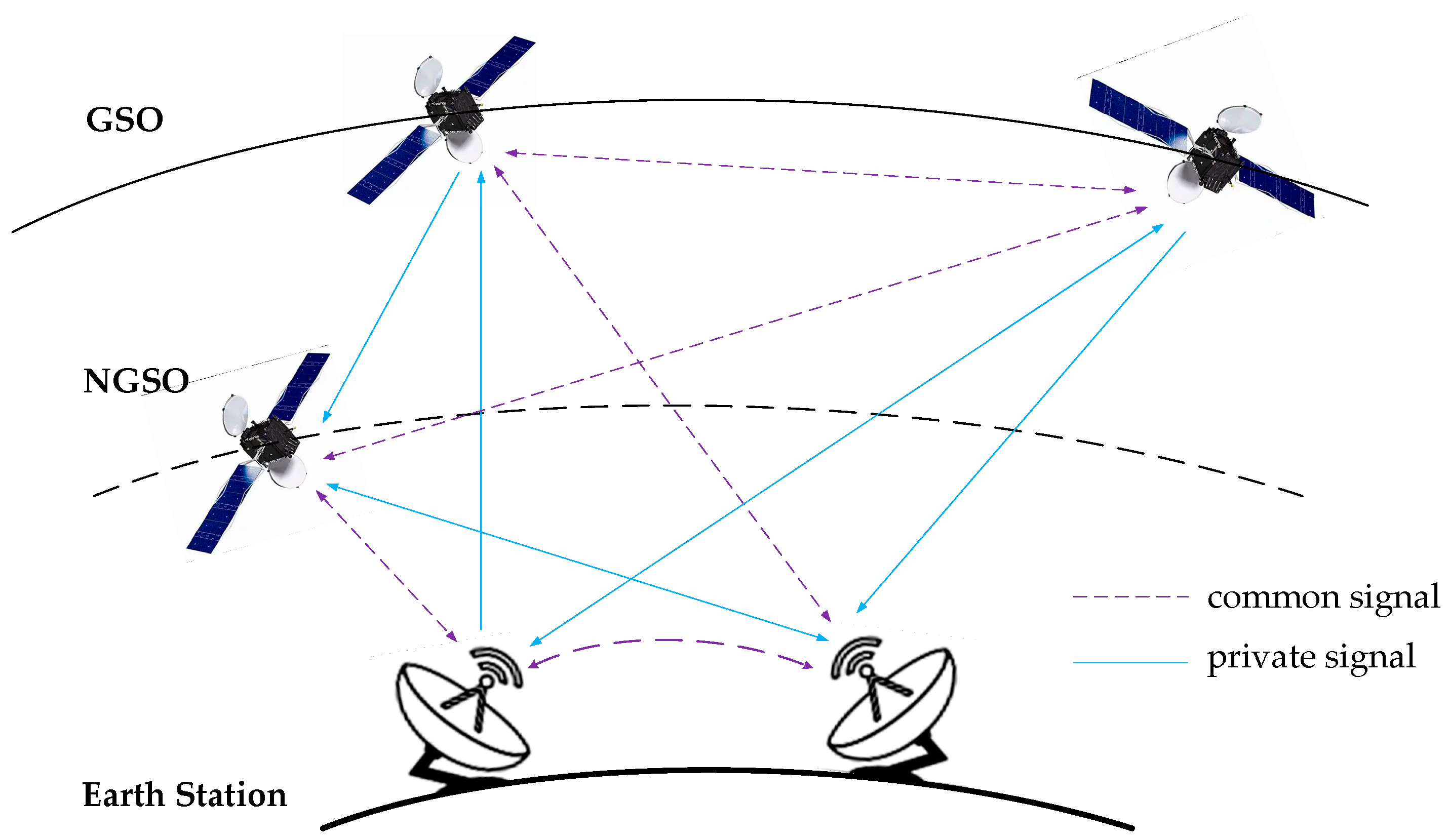
  • New communication scenarios often require each user to send and receive private as well as public information, which is called heterogeneous signal transmission. Users transmit heterogeneous signals at the same time, which leads to a sharp increase in the complexity of signal processing at relay nodes, and also increases the difficulty of interference suppression for receiving users.
  • The existing algorithms aim to emphasize how to construct the spatial alignment of interactive signals, however, there is less consideration given to the correlation between different alignment directions. If the alignment direction can be jointly optimized, the Euclidean distance between the received signals can be expanded and the decoding accuracy can be improved.
  • At present, most of the PNC principles only consider the use of low-dimensional modulation such as Binary Phase Shift Keying (BPSK) or Quadrature Phase Shift Keying (QPSK) in the additive white Gaussian noise (AWGN) channel to verify the feasibility of the scheme. At this time, it is relatively easy for multiple access signals to obtain PNC symbols based on an XOR operation. However, in real environments, wireless channels are time-varying channels with fading, and actual communication systems often use higher order modulation to improve spectral efficiency. In these cases, PNC-based or simple XOR will have application limitations due to fuzzy mapping.
The spatial degrees of freedom of a relay signal are optimized through machine learning to select the best precoding vector, and the selection of degrees of freedom can maximize the performance of the transmission. The design goal of effective utilization of wireless resources is to balance the performance of each user by using the degrees of freedom of antenna selection and transmission diversity gain. The main contributions of this paper are as follows:
  • According to the principle of minimum system antenna resource consumption and optimal interference suppression performance, public and private information are effectively separated by using signal subspace alignment and orthogonal subspace technology. In order to avoid mutual interference between the two types of information, it is necessary to ensure that the system can provide the optimal precoding vector selection mechanism no matter how the interference environment changes.
  • If the alignment directions can be orthogonal to each other, each bit is determined by the projection signal of the orthogonal axis. According to the orthogonal projection Euclidean distance of two possible points, the decoding process is simplified. By optimizing the orthogonal directions of different user pairs to determine order and power allocation, the ML decoding complexity is further simplified, and the decoding reliability is improved.
  • Aiming at the problem of constellation point ambiguity mapping in the high-order amplitude and phase modulation of PNC, a physical layer network coding denoising mapping algorithm is proposed. In this algorithm, relay nodes rearrange constellation points of received signals and merge constellation points according to certain rules. After processing, the signal constellation point is reduced by half. The Euclidean distance between the adjacent points of the constellation becomes larger, and the bit error rate (BER) performance of the system is improved.
The remainder of this paper is organized as follows: Section 2 formulates the system model and MIMO-Y channel in detail. In Section 3, signal spatial alignment is used to model the co-channel interference suppression problem, and a spatial reconstruction method is proposed to improve performance. Section 4 presents the simulation and experimental results in comparison with other interference suppression-based relay cooperative methods. Section 5 provides a discussion. Finally, Section 6 concludes the research work.

2. Signal Model

In view of the increasing number of non-geostationary satellite orbit (NGSO) constellation systems in the current space, there are more and more satellite networks with the same frequency band and adjacent orbits in use. The problem of co-frequency interference between NGSO constellation systems and between NGSO constellation systems and traditional geostationary satellite orbit (GSO) constellation systems is becoming increasingly serious. According to the transmission channel information of the satellite network, the precoding matrix of the transmitter matching characteristic channel is designed using the interference coordination technology in wireless communication. This is one of the important means to alleviate the problem of co-frequency interference in low earth orbit satellite networks.
According to the different types of new services, intelligent satellite networks can consider two different types of messages in multichannel relay channels: unicast and multicast messages. Unicast messages are used for dedicated users, which means that all other users treat this unicast message as an interference signal. On the other hand, a multicast message is used for a group of users, and it is received by all other users of the group. The unicast information sent by users to specific users is defined as a private signal, and the multicast information sent by users to specific groups is defined as a common signal. Each user tries to send both unicast (private) signals and multicast (common) signals to the other users in the multiple access channel (MAC) phase and decodes both of the signals in the broadcast channel (BC) phase. Figure 1 shows the intelligent satellite network transmission model.
The channel model includes K user nodes and a relay node, where each user node is equipped with M antennas and the relay node is equipped with N antennas. Assume that all nodes are in half duplex mode, and complete channel statement information (CSI) can be obtained. There is no direct link between different user nodes, and each user node sends a unicast message to the other K − 1 user nodes through the relay node. That is, each user sends information to two other users using the relay node. In the multiple access channel, the user node adopts interference alignment technology. In the broadcast channel, the relay node uses interference cancellation beamforming technology based on analog network coding to broadcast information to each user through Amplify Forward (AF). Reference [40] proved that the maximum degrees of freedom (DoF) of a MIMO-Y channel is K K 1 when the number of antennas M i i 1 , , K of user node i and the number of antennas N of a relay node satisfy M i K 1 , N K K 1 / 2 and N < min M i + M j , i j conditions.
In the MAC phase, user i sends two independent signals s [ j , i ] , j i 1 , 2 , 3 to the other two users. In order to eliminate the interference between co-channel users, the precoding vector v [ j , i ] is designed by using interference alignment. Assume that the elements satisfy the complex Gaussian independent identically distributed matrices A 1 and A 2 , whose size is N × M . Judging whether there is intersection subspace in the space stretched by two matrix column vectors is the precondition of precoding design to realize the alignment of interactive signals to the same signal dimension. The intersection subspace of user i and j can be expressed as follows:
s p a n H [ r , i ] v [ j , i ] = s p a n H [ r , j ] v [ i , j ]
where H [ r , i ] represents the N × M dimension channel transmission matrix from user i to the relay, and s p a n A represents the linear space formed by matrix A ; that is, whether there is a vector q i M × 1 satisfying q = A 1 q 1 = A 2 q . This condition can be rewritten as follows:
I N A 1 0 I N 0 A 2 q q 1 q 2 = P x = 0
From Formula (2), we can see that the problem of the existence of intersection subspaces is transformed into proving whether there is null space for matrix P . According to the rank zero theorem of linear algebra, as long as the number of columns of the matrix is greater than the rank of the matrix, then the null space exists. It is easy to see that the size of matrix P is 2 N × 2 M + N .
dim n u l l P = 2 M + N min 2 N , 2 M + N = 2 M N 1
When the user is equipped with M i = K 1 antennas and the relay is equipped with N = K K 1 / 2 antennas, it can be seen from Equation (3) that there is at least 1-dimensional intersection subspace. In other words, a pair of interactive user information can be aligned in the signal space. Therefore, the sending node designs a precoding vector, so that the following formula is true:
H [ r , 1 ] v [ 2 , 1 ] = H [ r , 2 ] v [ 1 , 2 ] = U 12 H [ r , 1 ] v [ 3 , 1 ] = H [ r , 3 ] v [ 1 , 3 ] = U 13 H [ r , K 1 ] v [ K , K 1 ] = H [ r , K ] v [ K 1 , K ] = U ( K 1 ) K
After signal space alignment (SSA), the signal received by the relay can be expressed as:
y [ r ] = i = 1 K H [ r , i ] j = 1 , j i K v [ j , i ] s [ j , i ] + n [ r ] = U 12 U 13 U ( K 1 ) K s [ 1 , 2 ] + s [ 2 , 1 ] s [ 1 , 3 ] + s [ 3 , 1 ] s [ K 1 , K ] + s [ K , K 1 ] + n [ r ] = U [ r ] s [ r ] + n [ r ]
where s i j [ r ] = s [ i , j ] + s [ j , i ] i , j { 1 , , K } , i < j . The relay adopts zero forcing decoding (ZF) and obtains aligned superimposed signals by inverting matrix U [ r ] . The physical layer network coding is used to map and modulate the superimposed signal and is broadcast in BC stage.
The relay signals to be transmitted in BC stage are s 12 [ r ] , s 13 [ r ] , , s ( K 1 ) K [ r ] . For receiving node 1, the desired received signals are the signals s 12 [ r ] , , s 1 K [ r ] transmitted by node 2 to node K. s 23 [ r ] , , s ( K 1 ) K [ r ] , form interference for user 1. The null space precoding vector is designed to eliminate unwanted interference signals.
v i j [ r ] n u l l H [ 1 , r ] n u l l H [ m , r ] n u l l H [ K , r ] , m i a n d m j
Taking user 1 as an example, the received signal is as follows:
y [ 1 ] = H [ 1 , r ] i = 1 , j > i K v i j [ r ] s i j [ r ] + n [ 1 ]
Using ZF decoding, the desired signals s 12 [ r ] , , s 1 K [ r ] of user 1 can be obtained, respectively. If BPSK is selected as the modulation mode, the expected signal can be obtained by XOR ( ) operation of the signal sent by the user node itself, and by the received signal.
s ^ [ i , j ] = s [ j , i ] s [ i , j ] s [ j , i ]
Most of the superimposed signals used by the multidirectional relay communication system only consider BPSK or QPSK modulation in the additive white Gaussian noise (AWGN) channel. At this time, the multiple access signals can use a simple XOR operation to obtain PNC coding symbols. PNC has constellation point mapping ambiguity in higher order amplitude and phase modulation. We will discuss the solution in the next section.

3. Signal Spatial Reconstruction Method for Relay Cooperative Networks

Multi-satellite cooperative transmission is the key for remote sensing systems to realize global real-time observation and low-time delay remote sensing information transmission. In order to reduce the inter-beam interference and improve the system throughput, source satellite multiple modal transmission and the channel of relay transmission must be considered as a multidirectional relay channel for multibeam joint design. This can optimize transmission scheduling and intelligent information distribution. According to the channel characteristics, a co-channel transmission scheme for multiple unicast packets and multicast services is designed. This can save limited time-frequency resources and improve system transmission efficiency. By optimizing the signal space structure, orthogonal signal alignment directions are constructed. According to the difference in transmission channel quality, signal alignment order is determined to reduce the impact of transmission quality bottlenecking in the system performance. In order to further improve the transmission efficiency of the system and increase the channel capacity, a constellation point remapping scheme is proposed for the fuzzy mapping problem of high order modulation in the physical layer network coding of relay node. The implementation framework of the method is shown in Figure 2.

3.1. Heterogeneous Signal Transmission under Multi Beam

The high-throughput satellite communication system mainly adopts unicast transmission when providing point-to-point services for users. However, this physical layer transmission mode cannot be directly applied to the rapidly growing multicast services. Multicast transmission can use the same wireless resources to save wireless time-frequency resources for users with the same service request and can provide services for users according to their channel characteristics. This paper optimizes the transmission performance of the physical layer, using the same wireless resource to provide transmission services for multiple unicast packets and multicast services simultaneously.
The unicast information sent by users to specific users is defined as a private signal, and the multicast information sent by users to specific groups is defined as a common signal. In the MAC phase, the private signal sent by user i to user j is s p [ j , i ] , and the common signal sent by user i is s c [ i ] . The transmitting node uses the beamforming technology of multiple antennas to design precoding vectors v p [ j , i ] and v c [ i ] respectively. Each user designs a private precoding vector to align the interactive pair of user signals to the same signal space. Equation (1) becomes
s p a n H [ R , i ] v p [ j , i ] = s p a n H [ R , j ] v p [ i , j ]
Except for user 1 and user K, each user i sends two common signals with the same content, that is
x c [ i ] = v c , 1 [ i ] s c [ i ] + v c , 2 [ i ] s c [ i ] , v c , 1 [ 1 ] = v c , 2 [ K ] = 0
The designed common coding rule is that the second common signal of user i − 1 must aligned with the first common signal of user i, and the second common signal of user i must be aligned with the first multicast message of user i + 1.
s p a n H [ R , i 1 ] v c , 2 [ i 1 ] = s p a n H [ R , i ] v c , 1 [ i ] s p a n H [ R , i ] v c , 2 [ i ] = s p a n H [ R , i + 1 ] v c , 1 [ i + 1 ]
Taking 4 users as an example, suppose that the user is equipped with 7 antennas and the relay is equipped with 13 antennas. According to Equations (9) and (11), the private alignment direction combination is U p = u p π ( 1 , 2 ) u p π ( 1 , 3 ) u p π ( 1 , 4 ) u p π ( 2 , 3 ) u p π ( 2 , 4 ) u p π ( 3 , 4 ) and the common alignment direction combination is U c = u c , 1 u c , 2 u c , 3 which can be obtained by using the method of Formula (4), respectively. Where π i , j represents the linear index combination function of unordered pair i , j . After signal space alignment, the signal received by the relay can be expressed as follows:
y [ r ] = i = 1 4 H [ r , i ] j i v p [ j , i ] s p [ j , i ] + v c , 1 [ i ] s c [ i ] + v c , 2 [ i ] s c [ i ] + n [ r ] = U p U c s p [ r ] s c [ r ] + n [ r ]
where v c , 1 [ 1 ] = v c , 2 [ 4 ] = 0 M × 1 , s p [ r ] = s p [ 1 , 2 ] + s p [ 2 , 1 ] s p [ 1 , 3 ] + s p [ 3 , 1 ] s p [ 1 , 4 ] + s p [ 4 , 1 ] s p [ 2 , 3 ] + s p [ 3 , 2 ] s p [ 2 , 4 ] + s p [ 4 , 2 ] s p [ 3 , 4 ] + s p [ 4 , 3 ] , s c [ r ] = s c [ 1 ] + s c [ 2 ] s c [ 2 ] + s c [ 3 ] s c [ 3 ] + s c [ 4 ] .
Using ZF decoding, the relay can obtain six private superimposed signals and three common superimposed signals, respectively. In the BC stage, the BPSK modulated signal modulates and maps the superimposed signal according to the physical layer network coding principle [41] to obtain the signal to be transmitted s r = s r , p 1 , s r , p 2 , s r , p 3 , s r , p 4 , s r , p 5 , s r , p 6 , s r , c 1 , s r , c 2 , s r , c 3 T . According to Equation (6), the null space precoding vector v r = v r , p 1 , v r , p 2 , v r , p 3 , v r , p 4 , v r , p 5 , v r , p 6 , v r , c 1 , v r , c 2 , v r , c 3 is designed to eliminate unwanted interference signals.
In order to eliminate interference signals s r , p 4 , s r , p 5 and s r , p 6 , user 1 needs to make precoding vectors v r , p 4 , v r , p 5 and v r , p 6 lie in the null space of the channel transmission matrix. Similarly, the precoding vectors v r , p 2 , v r , p 3 and v r , p 6 need to be located in the null space of the channel transmission matrix H [ 2 , r ] to eliminate the interference of user 2. The precoding vectors v r , p 1 , v r , p 3 and v r , p 5 need to be located in the null space of the channel transmission matrix H [ 3 , r ] to eliminate the interference of user 3. The precoding vectors v r , p 1 , v r , p 2 and v r , p 4 need to be located in the null space of the channel transmission matrix H [ 4 , r ] to eliminate the interference of user 4. It can be found that the precoding vector v r , p 6 needs to be located in the null space of H [ 1 , r ] and H [ 2 , r ] . That is, v r , p 6 n u l l H [ 1 , r ] n u l l H [ 2 , r ] . Therefore, 6 antennas from 7 antennas of each user are selected as receiving antennas to form channel transmission matrix H ^ [ i , r ] with 6 × 13 dimensions to meet the null space existence condition N < 2 M . Using the same method, the design for the remaining receive precoding vectors is as follows:
H ^ [ 3 , r ] H ^ [ 4 , r ] v r , p 1 = 0 , H ^ [ 2 , r ] H ^ [ 4 , r ] v r , p 2 = 0 H ^ [ 2 , r ] H ^ [ 3 , r ] v r , p 3 = 0 , H ^ [ 1 , r ] H ^ [ 4 , r ] v r , p 4 = 0 H ^ [ 1 , r ] H ^ [ 3 , r ] v r , p 5 = 0 , H ^ [ 1 , r ] H ^ [ 2 , r ] v r , p 6 = 0
The signals received by user 1 is as follows:
y [ 1 ] = H ^ [ 1 , r ] m = 1 6 v R , p m s R , p m + n = 1 3 v R , c n s R , c n + n [ 1 ] = Q ^ [ 1 , r ] s R , p 1 s R , p 2 s R , p 3 s R , c 1 s R , c 2 s R , c 3 T + n [ 1 ]
where Q ^ [ 1 , r ] represents the equivalent transmission channel after antenna selection. User 1 adopts ZF decoding. According to Equation (8), the desired signal can be obtained by using the signal sent by user 1. In particular, user 1 can obtain s c [ 2 ] by using its own signals s c [ 1 ] and s R , c 1 for multicast signals. s c [ 3 ] can be obtained by reusing s c [ 2 ] and s R , c 2 . Finally, s c [ 4 ] can be obtained by using s c [ 3 ] and s R , c 3 . Other users can use the same method to obtain their respective desired signals.

3.2. Orthogonal Optimization of Signal Space

Take the MIMO multiway channel model of 3 users as an example to introduce the implementation process [25]. In traditional signal space alignment, the number of antennas configured for each user node is 2. The corresponding upstream channel matrix H [ r , i ] is 3 × 2 dimensions, and the precoding vector is 2 × 1 dimensions. According to the signal space alignment conditions given in Section 2, the three alignment signals at the relay node are uniquely determined. That is, the three spatial directions U 12 , U 13 and U 23 are also fixed.
In order to realize the orthogonal alignment of signal subspaces, the redundancy of user node antennas is needed. Thus, the flexibility of a user’s precoding vector selection is increased. Therefore, when the number of antennas of the user node is increased to 3, the number of antennas of the relay node is kept unchanged. Currently, its corresponding uplink channel matrix H [ r , i ] is 3 × 3 dimensions, and the precoding vector is 3 × 1 dimensions. According to the condition of signal space alignment, each pair of precoding vectors has 6 unknown parameters. From the 3 aligned equality constraints, each pair of direction vectors is determined in a 3D signal space. However, when compared with the traditional MIMO-Y channel model, the selection of U 12 , U 13 and U 23 dimensions are more flexible, and the selection gain of the system will increase accordingly.
According to the system model of MIMO-Y, the signals received by the relay node in the MAC phase can be expressed as follows:
y [ r ] = H [ r , 1 ] v [ 2 , 1 ] s [ 2 , 1 ] + H [ r , 2 ] v [ 1 , 2 ] s [ 1 , 2 ]   + H [ r , 1 ] v [ 3 , 1 ] s [ 3 , 1 ] + H [ r , 3 ] v [ 1 , 3 ] s [ 1 , 3 ]   + H [ r , 2 ] v [ 3 , 2 ] s [ 3 , 2 ] + H [ r , 3 ] v [ 2 , 3 ] s [ 2 , 3 ] + n [ r ]   = U 12 ( s 12 ) + U 13 ( s 13 ) + U 23 ( s 23 ) + n [ r ]
where U i j is the direction of the signal space formed by the relay node for the interaction signal of the user node pair i , j , and s i j represents the superposition signal of s [ i , j ] and s [ j , i ] , i.e., s i j = s [ i , j ] + s [ j , i ] . Figure 2 is a graph of signal space alignment results formed at the relay nodes.
It can be seen from Figure 3 that six signals sent by three user nodes are aligned in two at the relay, forming three signal space directions. The signals in the direction of each signal space are the sum of the interactive signals. In order to make the three spatial directions formed after alignment on the relay node mutually orthogonal, the following requirements shall be met:
U 12 H U 13 = 0 U 12 H U 23 = 0 U 13 H U 23 = 0
In terms of precoding vector design and channel matrix, it is necessary to achieve:
H [ r , 2 ] v [ 1 , 2 ] H H [ r , 3 ] v [ 1 , 3 ] = 0 H [ r , 2 ] v [ 1 , 2 ] H H [ r , 3 ] v [ 2 , 3 ] = 0 H [ r , 3 ] v [ 1 , 3 ] H H [ r , 3 ] v [ 2 , 3 ] = 0
According to the above analysis, the principle of realizing orthogonal alignment of signal subspace is to design the transmission precoding vector in MAC phase. The condition of signal space alignment is H [ r , 1 ] v [ 2 , 1 ] = H [ r , 2 ] v [ 1 , 2 ] H [ r , 1 ] v [ 3 , 1 ] = H [ r , 3 ] v [ 1 , 3 ] H [ r , 2 ] v [ 3 , 2 ] = H [ r , 3 ] v [ 2 , 3 ] , i.e.,
v [ 2 , 1 ] v [ 1 , 2 ] = n u l l H [ r , 1 ] H [ r , 2 ]
where H [ r , 1 ] H [ r , 2 ] is a matrix of 3 × 6 in dimensions. If these conditions are met, n u l l H [ r , 1 ] H [ r , 2 ] has a redundancy of 6 3 = 3 dimensions. Each direction is regarded by a vector of 6 × 1 dimensions. In other words, there are three groups of selectable vectors in this group of solved precoding vectors. Therefore, the corresponding aligned spatial direction of this group of precoding vectors formed on the relay node also has three directions to choose from. On the other hand, the first determined spatial direction will affect the precoding vectors of the other two spatial directions.
If the first determined spatial direction is U 12 , its corresponding precoding vectors v [ 2 , 1 ] , v [ 1 , 2 ] are also determined. According to orthogonality conditions, another two groups of precoding vectors can be obtained:
v [ 1 , 3 ] = n u l l ( v [ 1 , 2 ] H H [ r , 2 ] H H [ r , 3 ] ) v [ 2 , 3 ] = n u l l ( v [ 1 , 2 ] H H [ r , 2 ] H H [ r , 3 ] )
It can be seen from the above formula that v [ 2 , 3 ] and v [ 1 , 3 ] are in the same null space. In the above formula, n u l l ( v [ 1 , 2 ] H H [ r , 2 ] H H [ r , 3 ] ) has 3 1 = 2 directional dimensions. Each direction can be regarded by a vector of 3 × 1 dimensions. Similarly, the orthogonality condition between U 12 and U 13 must be satisfied when determining v [ 2 , 3 ] and v [ 1 , 3 ] . According to the above analysis, v [ 1 , 3 ] is represented by v [ 1 , 3 ] = a 1 x + b 1 y , v [ 2 , 3 ] is represented by v [ 2 , 3 ] = a 2 x + b 2 y . x and y are a group of 3 × 1 -dimensional bases in null space. After a 1 and b 1 are arbitrarily selected, v [ 1 , 3 ] , v [ 3 , 1 ] and U 13 are determined according to the signal space alignment condition of v [ 3 , 1 ] v [ 1 , 3 ] = n u l l H [ r , 1 ] H [ r , 3 ] . Therefore, the second spatial direction can be determined.
When solving the third spatial direction, the orthogonality condition in Equation (17) can give:
a 1 b 1 x y H H H [ r , 3 ] H H [ r , 3 ] x y a 2 b 2 T = 0
After the above equations a 1 and b 1 are determined, only the unknowns a 2 and b 2 are not determined. Therefore, after the precoding vector v [ 1 , 3 ] is determined, v [ 2 , 3 ] can be obtained from the alignment condition:
v [ 3 , 2 ] v [ 2 , 3 ] = n u l l H [ r , 2 ] H [ r , 3 ]
After solving v [ 2 , 3 ] by Equation (21), the third spatial direction U 23 can also be uniquely determined according to the corresponding channel matrix. The three spatial directions determined by this method are mutually orthogonal, realizing the orthogonal alignment of the signal subspace. In the traditional orthogonal alignment of signal subspaces, the selection of each signal space direction has randomness. The first alignment signal spatial direction is not based on the principle of optimal performance, so the performance of this scheme cannot reach the optimal level. It is therefore necessary to improve alignment.

3.2.1. Analysis of Antenna Number Configuration

For the MIMO-Y channel model of K users, the requirements for the number of antennas to achieve orthogonal alignment of signal subspaces are analyzed as follows: for example, to meet the signal space alignment conditions of user 1 and user 2,
H [ r , 1 ] H [ r , 2 ] v [ 2 , 1 ] v [ 1 , 2 ] = 0
and the redundancy of user node antenna is required to realize the spatial alignment of orthogonal signals. According to the matrix null space theory, the left matrix of the formula shall meet the following requirements in dimension: c o l u m n r o w k ( k 1 ) 2 . Therefore, the minimum requirements for antenna configuration shall meet the following: M = K ( K 1 ) 2 , N = K ( K 1 ) 2 .

3.2.2. Analysis and Improvement of Signal Spatial Direction Solving Order

In the process of realizing orthogonal alignment of signal subspaces to solve the precoding vector, the sequence determined by the alignment direction of each signal space and the solution sequence of user nodes sending precoding vectors will directly affect the bit error rate performance of user pairs corresponding to interactive signals. When implementing the signal subspace orthogonal alignment algorithm, the spatial alignment direction that is first solved and determined has the largest degrees of freedom of selection. Therefore, the best bit error rate will be obtained. Then the spatial alignment direction is solved and determined. Due to the decreasing degrees of freedom of selection, the bit error rate performance decreases. The bit error rate performance of the interactive signal corresponding to the finally determined spatial alignment direction has the worst channel quality. Therefore, the performance bottleneck of the system is to ensure that the signal space alignment direction of the interactive signal pair with the worst transmission channel quality is determined first. Therefore, the idea to improve the performance is to determine the solution order of the spatial direction of the interactive signal formation alignment according to the quality of the upstream channel from each user node to the relay node. That is, the first alignment direction that is solved and determined is the interactive signal with the worst channel quality. Finally, the spatial direction of the interactive signal with the best channel quality is determined.
In solving the precoding vector and determining the spatial alignment direction formed by relay nodes, the selection gain of channel quality is used to compensate for the disadvantages of poor channel quality to improve the overall system performance. Therefore, before solving the appropriate precoding vector, the channels between user nodes and relay nodes in the system should be sorted according to channel quality. Then, the spatial alignment direction and precoding vector of the interactive signals are solved according to the channel ordering.

3.2.3. Optimization of Precoding Vector

For the solution to the orthogonal alignment scheme of signal subspace, according to the transmission quality of the detection channel, the sequence of the channel matrix from poor to excellent is recorded as H [ r , 1 ] , H [ r , 2 ] , H [ r , 3 ] . At the same time, users are numbered as 1, 2 and 3, in this order. Then, the transmit precoding vector is redesigned to achieve the orthogonal alignment of signal subspace.
First, the interactive signals corresponding to the worst transmission channel matrix H [ r , 1 ] and the subworst channel matrix H [ r , 2 ] (i.e., the interactive signals between user nodes 1 and 2) are designed by precoding the transmission in the MAC phase. When relay nodes are aligned to the same signal space direction, the conditions for alignment according to the signal space are as follows:
H [ r , 1 ] v [ 2 , 1 ] = H [ r , 2 ] v [ 1 , 2 ]
The transmission precoding matrix of the interactive signal pairs of user nodes 1 and 2 is Equation (18), where the transmission precoding vectors v [ 2 , 1 ] and v [ 1 , 2 ] are 3 × 1 dimensions, and the corresponding null space matrix dimensions are 6 × 3 dimensions. When solving the transmission precoding vector of interactive signal pair 1 and 2, a column vector can be selected from the 3D space of the null space matrix n u l l H [ r , 1 ] H [ r , 2 ] . This is used as the transmission precoding vector of the interactive signal pair. The principle for selecting column vectors is to calculate the modulus of each column vector in the null space matrix, and use the column vector with the largest modulus as the transmission precoding vectors v [ 2 , 1 ] and v [ 1 , 2 ] of user nodes 1 and 2. After the first set of precoding vectors v [ 2 , 1 ] and v [ 1 , 2 ] are determined, the aligned signal space direction formed by the relay node is also uniquely fixed. Namely:
U 12 = H [ r , 1 ] v [ 2 , 1 ] = H [ r , 2 ] v [ 1 , 2 ]
After the first signal spatial direction formed on the relay node is determined, the second set of transmission precoding vectors and alignment directions are solved according to the first determined spatial alignment direction and orthogonality. The specific solution is as follows: first, define a matrix P . The initial value of P is the determined spatial direction of the first alignment, i.e., P = [ U 12 ] . Then, using the properties of orthogonal projection, the orthogonal projection matrix of matrix P is obtained.
Q = I N P P H P 1 P H
The second signal space alignment direction can be obtained by using the orthogonal projection matrix Q N N . The method is to deconstruct Q N N into eigenvalues and find the eigenvector corresponding to its maximum eigenvalue. This eigenvector is used as the interactive signal of user nodes 1 and 3 in the spatial alignment direction U 13 formed by the relay. After the spatial direction of alignment is determined, the corresponding transmission precoding vector can be inversely solved by using the channel matrix. That is, v [ 3 , 1 ] and v [ 1 , 3 ] can be obtained from U 13 = H [ r , 1 ] v [ 3 , 1 ] = H [ r , 3 ] v [ 1 , 3 ] . Therefore, the spatial alignment direction formed by the relay for the second group of transmission precoding vectors and interactive signal pairs is determined. The third group of precoding vectors and the corresponding alignment direction are determined according to the second aligned spatial direction. First, the matrix P takes the space direction vectors U 12 and U 13 that have been previously solved as its column vectors in turn. That is, P = [ U 12 U 13 ] . Then, the transmission precoding vectors v [ 3 , 2 ] and v [ 2 , 3 ] are determined in the same way.
The above method is extended to the communication system of K user. Starting from solving the second group of precoding vectors and their corresponding spatial directions, the column vectors in matrix P are composed of the previously determined spatial directions. The new alignment direction is located in the space of the orthogonal projection matrix Q .

3.3. Extended to K Users

In this section, we extend the above algorithm to a more general case where the number of users is K. At this time, any two user pairs can send signals between them. Each user sends K 1 private signals and one common signal through space separation technology. Therefore, the relay will receive a total of ( K 1 ) × K + K = K 2 signals from K users in the MAC phase. To separate private signals and common signals sent by each node, it must meet
M ( K + 1 )
In order to align the private signals and the common signal to the appropriate intersection subspace at the relay, the space precoding vectors v p [ j , i ] and v c , k [ i ] must be designed to satisfy s p a n H [ r , i ] v p [ j , i ] = s p a n H [ r , j ] v p [ i , j ] and s p a n H [ r , i ] v c , 2 [ i ] = s p a n H [ r , i + 1 ] v c , 1 [ i + 1 ] , if
2 M N + 1
If the above conditions are satisfied, the intersection subspace composed of the column space of the equivalent channel matrix must exist.
If each user sends K 1 private signals, K ( K 1 ) private signals will be transmitted simultaneously in the K-user network. For the K-user network to send common signals, we designed a novel transmission structure. User 1 and user K only send one common signal, while the other users send two copies of the common signal in two different directions. That is, x c [ i ] = v c , 1 [ i ] s c [ i ] + v c , 2 [ i ] s c [ i ] , v c , 1 [ 1 ] = v c , 2 [ K ] = 0 . The principle for determining the transmission direction is that the second signal of the current user is spatially aligned with the first signal of the next user, s p a n H [ r , i ] v c , 2 [ i ] = s p a n H [ r , i + 1 ] v c , 1 [ i + 1 ] , i = 1 , , K 1 .
The relay needs enough signal space to accommodate K ( K 1 ) / 2 private signals and K 1 common signals. Therefore, the number of relay antennas must meet
N K ( K 1 ) / 2 + ( K 1 ) = ( K 1 ) ( K + 2 ) / 2
while the relay obtains the K 2 signals during the MAC phase.
In the BC phase, in order to be correctly decoded by the target user, the interference of other signals must be suppressed. For private signals, we designed precoding vectors q p [ i , j ] and q p [ j , i ] to satisfy s p a n q p [ i , j ] H [ i , r ] = s p a n q p [ j , i ] H [ j , r ] . For common signals, we designed precoding vectors q c [ i , j ] and q c [ j , i ] to satisfy s p a n q c [ i , j ] H [ i , r ] = s p a n q c [ j , i ] H [ j , r ] , the size of which is ( K × ( K 1 ) ) × N . The intersection subspace of the private signal and public signal of user i and user j is defined as z p π p ( i , j ) and z c π c ( i , j ) , respectively. All the intersection subspaces together constitute the equivalent transmission channel. Z = z p π p ( 1 , 2 ) z p π p ( K 1 , K ) z c π c ( 1 , 2 ) z c π c ( K 1 , K ) H . Z ˜ p π p ( i , j ) is defined as an equivalent matrix that does not contain z p π p ( i , j ) .
Therefore, if
N K × ( K 1 )
the set of solutions for n u l l Z ˜ p π p ( i , j ) exists. We can therefore conclude that T p π p ( i , j ) n u l l Z ˜ p π p ( i , j ) . For the common signals, Z ˜ c ϕ ( K , i ) is defined as an equivalent matrix that does not contain ϕ ( K , i ) = π c ( s , t ) , , π c ( m , n ) 1 × K / 2 . Z ˜ c ϕ ( K , i ) indicates that K / 2 common vectors satisfying z c π c ( s , t ) , , z c π c ( m , n ) , a n d s t m n are removed from all K × ( K 1 ) / 2 common signal vectors. It can define T c i n u l l Z ˜ c ϕ ( K , i ) .
The received signals at user i can be expressed as
y [ i ] = Q [ i ] H [ i , r ] m = 1 K ( K 1 ) / 2 T p m s R , p m + n = 1 K 1 T c n s R , c n + n [ i ]
where Q [ i ] = q p [ i , 1 ] q p [ i , 2 ] q p [ i , K ] q c [ i , 1 ] q c [ i , 2 ] q c [ i , K ] T . The equivalent matrix H ^ [ i , r ] = Q [ i ] H [ i , r ] of relay to user i is a diagonalization matrix.
In order to further improve system capacity, the private signals degrees of freedom sent by each user can be increased from 1 to d p . Similarly, the degrees of freedom of the common signals can be increased to d c . d p K K 1 private signals and 2 d c K 1 common signals will be sent to the relay at the same time. If the number of user antennas and the number of relay antennas meet M = 1 2 ( N + d p + d c ) and N 1 2 d p K K 1 + 1 2 d c K K 1 respectively, the DoF of η s u m ( K ) = d p K ( K 1 ) + d c K can be achieved.

3.4. Physical Layer Adaptive High Order Modulation

BPSK modulation is more widely used in the research of bidirectional relay physical layer network coding. However, there is constellation ambiguity in high order amplitude and phase modulation. In order to solve this problem, the relay node rearranges the constellation points of the received signals. We can therefore reduce the number of signal constellation points through constellation point merging. The Euclidean distance between adjacent constellation points becomes larger, and the system bit error rate performance is improved.
The design of M-QAM constellation mapping must be combined with PNC to ensure the existence of mapping function G. Reference [41] gives the conditions for the existence of the PNC mapping function G: if there is C , , M : C X to make G : c r s r exist, it must satisfy c i , c j C and x i = M c i , x j = M c j . If there is c i c j = s r , then G x i + x j = s r . That is G M c i + M c j = s r , where C is the source symbol set, X is the set of modulated signals, c r = c i + c j is the symbol set after x i + x j demodulation, and is the PNC mapping operator.
Since M-QAM is the superposition of two in-phase and quadrature M -PAM signals, only the design of M-QAM in-phase M -PAM modulation constellation mapping needs to be considered. The algorithm shall ensure that the corresponding PNC mapping function G exists. For M -PAM modulation, the only necessary and sufficient condition for PNC mapping to be solvable is that any L = M consecutive constellation points of a superimposed signal constellation are mapped to different symbols. Table 1 lists the results of PNC using an M-QAM modulation–demodulation–remapping scheme, where x 1 + x 2 represents the superimposed in-phase signal received by the relay node, s r = G c 1 , c 2 represents the symbol after the PNC mapping, corresponding to the PNC mapping function G, and M R , L s r represents the M -PAM modulated signal of s r .
After receiving the superimposed signal, the relay node first demodulates the signal. Table 1 shows that if the user node adopts an M-ary QAM modulation scheme, the signal received by the relay node is equivalent to N = 2 L 1 2 ary QAM. That is, the in-phase branch is equivalent to the PAM in H = 2 L 1 ary. The mapping function G calculates the code word s r = c 1 c 2 = G c r = c 1 + c 2 mod L after PNC mapping. Finally, the symbol s r is modulated by L-PAM to obtain the modulated signal x r .
In the BC stage, node 1 demodulates the received signal with L-PAM to estimate s ^ r . Node 1 demaps signal s ^ r according to its own information c 1 , and estimates the information c ^ 2 = s ^ r c 1 mod L of node 2.

4. Numerical Results

The scheme studied in this paper mainly involves two aspects in performance analysis, communication capacity and bit error rate (BER). All MIMO channels in the simulation scheme are quasi-static flat fading channels. All nodes in the channel model can obtain channel state information (CSI). Each element in the channel matrix is independently identically distributed (i.i.d.), and all nodes operate in half-duplex mode. In this section, some simulations are given to verify the effectiveness of our proposed method. In the following simulations, we used MATLAB and Python as tools and all the nodes are equipped with Uniform Linear Array (ULA), as well as with M transmit elements and N receive elements that are separated by half a wavelength. Other specific simulation parameters are shown in Table 2.

4.1. Channel Quality Analysis

In order to reflect the channel quality of the communication link of a satellite communication system, the satellite communication model is equivalent to the baseband transmission model. Suppose that the communication satellite is basically aligned in the relay signal space, the communication frequency is 6 GHz, and the modulation mode is QPSK. The difference that channel quality makes on the propagation path has a very important impact on the channel selection and precoding design. The solution for the aforementioned signal subspace orthogonal alignment scheme should be designed according to the different channel qualities. For this reason, Figure 4 simulates three different quality transmission channels for simulating various communication environments.
Then, we evaluate how the correlation index of large-scale fading changes on the array effects of the channel estimation. The average correlation factor r of the antenna is shown in Figure 5. The fixed position of the target node is 30 degrees, and the effective SNR is 10 dB. The variable position of the interfering node covers θ [ π , π ) , and the effective SNR = 0 dB. Figure 5 shows that the larger the antenna number M, the lower the correlation between nodes. The larger the rank equivalent to the channel matrix, the more dispersed the eigenvalues are. In addition, it can be seen that whenever the interfering node has the same angle as the desired node, the correlation coefficient is equal to 1. That is, the estimates are completely correlated. This means that the estimates are parallel, and they can only be distinguished by scaling factors. This usually happens in the case of uncorrelated Rayleigh fading and a single antenna. If each node has a different angle, the correlation level between nodes will decrease. This highlights the fact that the completely different characteristic directions of nodes help to reduce the correlation between channel estimates. Another interesting phenomenon is related to correlation factors: when correlation factors increase, more spatial dimensions are obtained. This increases the difference between channels and reduces the impact between them.

4.2. Transmission Reliability

Aiming at the bottleneck problem of system performance, this paper proposes that the channels between user nodes and relay nodes in the system should be sorted according to transmission quality before solving the appropriate precoding vector. The new channels with poor quality rank first, and the channels with good quality rank last. Then, the spatial alignment direction formed by the interactive signals corresponding to the channel and its transmission precoding vector are solved step-by-step according to the ordered channels. Therefore, how to judge the quality of channel transmission is also a problem to be considered in this paper.
The quality of channel transmission is essentially determined by the channel transmission matrix. Therefore, the judgment standard of channel transmission quality is determined from the factors that determine the channel matrix. The size of the singular value obtained after the singular value decomposition of the channel matrix can represent the transmission gain of the equivalent channel. At the same time, the number of nonzero singular values is related to the channel capacity of the MIMO-Y channel model. Whether the distribution of singular values is uniform depends on the degrees of freedom of the channel matrix. Therefore, it can be inferred from the above analysis that the quality of channel transmission requires comprehensive consideration of two factors: the size of the singular value obtained from the singular value decomposition of the channel matrix and the distribution degree of the singular value. Taking these two determinants into account, this paper is based on the normal distribution probability density of the singular value of the channel matrix. The integration of the density function is taken as the standard to measure the quality of channel transmission. Specific judgment methods are as follows:
(i) The upstream channel matrix from each user node to the relay node in the channel model is decomposed into singular values, such as SVD decomposition of H r , 1 . In the three-user MIMO-Y channel model, three singular values can be obtained after decomposition.
(ii) A group of singular values obtained from the singular value decomposition of each channel matrix is represented by X , and the mean and variance of X are calculated. X follows the normal distribution, i.e., X N μ , σ 2 . The probability density function of normal distribution is:
f x = 1 σ 2 π e x μ 2 2 σ 2
where, μ is the mean value of data X , and σ 2 is the variance of data X . The integral of the positive half axis of the x -axis for function f x is:
t = 0 f x
The value of t is used to measure the quality of the channel transmission. Calculate the t value corresponding to the upstream channel matrix from each user node to the relay node, and then compare the t value. The larger the t value is, the better the channel transmission quality is. In addition to the normal distribution method based on the singular value of the matrix proposed above, there are two common methods: measure according to the mean value of the singular value of the channel matrix and measure according to the variance of the singular value of the channel matrix.
Figure 6a shows the simulation results of the bit error rate of the traditional SSA algorithm and the signal space orthogonal alignment algorithm varying with the signal to noise ratio. The simulation results show that the signal space orthogonal alignment algorithm further reduces the bit error rate of the system compared with the traditional signal space alignment algorithm. Therefore, the performance advantages of signal subspace orthogonality are verified. Figure 6b shows the simulation results of the change of bit error rate with a signal-to-noise ratio under two conditions for optimizing the solution order of signal spatial direction and random solution. According to the performance comparison in the Figure, the bit error rate is lower, and the system performance is significantly improved when the signal space order is determined. Therefore, the simulation results can verify that the maximum selection gain can be obtained by first solving the spatial alignment direction formed by the interactive signal corresponding to the worst transmission channel. The spatial alignment direction formed by the interactive signals corresponding to the channel with the best transmission quality is finally solved to achieve the balance of the system performance bottleneck. Figure 6c shows the MIMO-Y channels of 10 users with antenna configurations of 45 × 45 . The BER of the system varies with the SNR when different channel transmission quality criteria are used to determine the signal space alignment direction. It can be seen from the Figure that in the multiuser application scenario, the normal distribution of singular values of the channel matrix is comprehensively considered. At the same time, the scheme based on the variance of the singular value of the channel matrix to measure the channel quality is better than the scheme based on the mean value. Figure 6d shows the MIMO-Y channels of three users with an antenna configuration. Through four different communication schemes, the relationship between the system error rate and the change of SNR is compared. The four schemes are traditional signal space alignment and signal subspace orthogonal alignment. The column vector with the largest modulus in the orthogonal projection matrix is selected as the precoding vector, and is the precoding vector optimization proposed in this paper. From the simulation results, it can be seen that moving from signal space alignment to signal subspace orthogonal alignment shows a substantial improvement in the system’s bit error performance. This also confirms the necessity of realizing the orthogonal alignment of signal subspaces. Furthermore, as far as the signal subspace orthogonal alignment algorithm is concerned, the simulation results show that the performance of the improved algorithm proposed in this paper is also significantly improved compared with other methods. Therefore, the improvement of the effectiveness of the integrated power allocation, the optimized precoding vector, and the order to determine the spatial alignment direction of the interactive signals can greatly promote the improvement of system performance.
Figure 7 compares the BER performance of different schemes after suppressing co-channel interference. MIMO beamforming takes up the same time-frequency resources and uses spatial resources to divide spatially separable transmission paths. Its transmission quality is significantly better than that of multiple parallel data streams constructed by a MIMO multiuser. Transformed Subspace [32] allows messages to be exchanged by applying improved signal space alignment for network coding and interference cancelation when antennas configuration extends to N > 2 M . The proposed scheme develops the potential of signal space and constructs mutually orthogonal signal space alignment directions. According to channel quality selection and power allocation, the minimum European distance of constellation points is increased. This can improve the BER performance of the system. Therefore, the BER performance of the proposed scheme is the best.

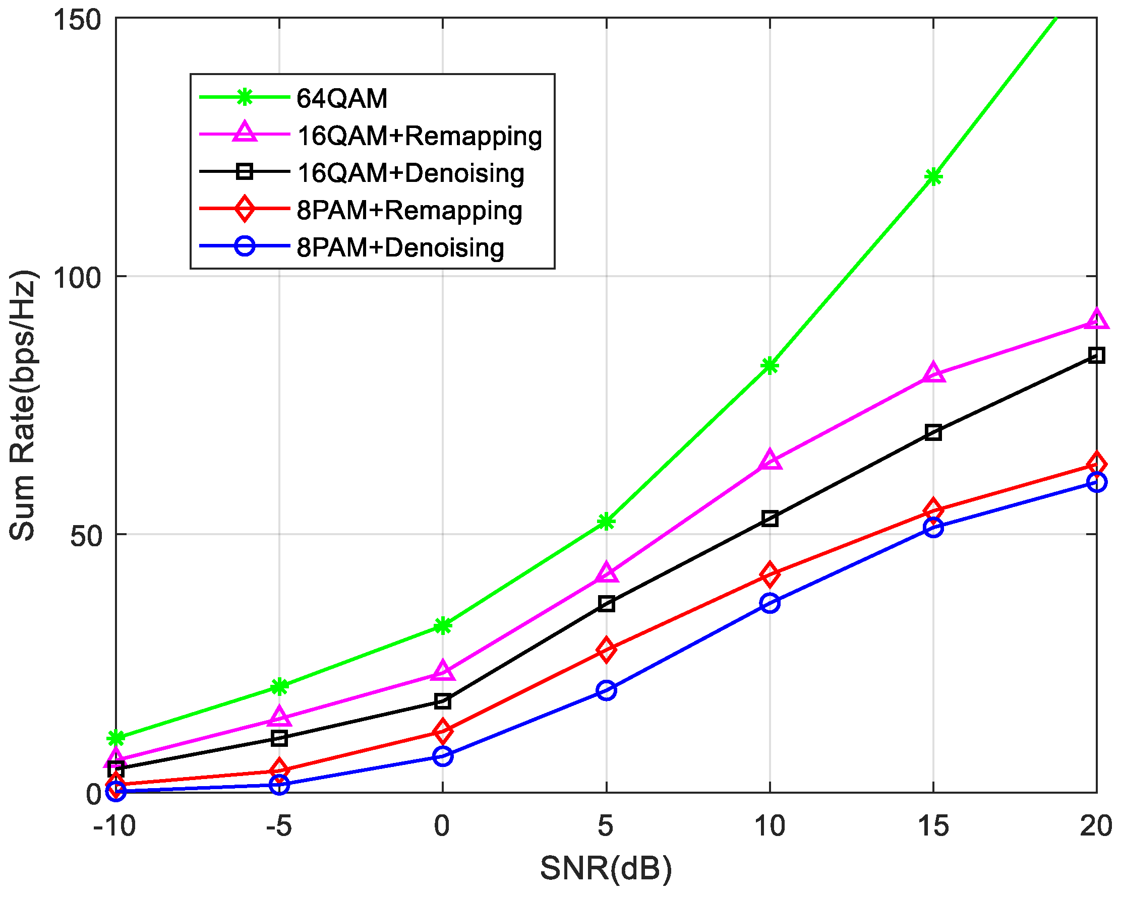
4.3. Spectral Efficiency

In the traditional denoising forwarding scheme, the relay receives signal y = x 1 + x 2 + n . The constellation point of the in-phase branch of the transmitted signal after noise elimination mapping is 2 L + 2 , 2 L + 4 , , 2 L 4 , 2 L 2 . Phase BC is approximately NQAM, i.e., N = 2 L 1 2 . If the modulation mode is 16 QAM, the signal received by the node is approximately 49 QAM. The signal received by the node in this scheme is still a 16 QAM. With the increase in the modulation order of the user, the modulation order of the signal received by the node increases exponentially. In the broadcast transmission phase, the distance between the constellation points of the modulation mapping scheme proposed in this paper is twice that of the denoising scheme. The scheme proposed in this paper solves the constellation ambiguity problem in the high order amplitude and phase modulation of bidirectional relay physical layer network coding. The number of signal constellation points is reduced by repositioning and merging the received signals at the relay node. The Euclidean distance between adjacent constellation points becomes larger, and the system bit error rate performance is improved. Figure 8 shows that the scheme in this paper can break through the limitations of BPSK modulation and adopt higher-order modulation when the relay encodes the aligned superimposed signal in the physical layer network. A greater sum rate can be obtained when 64 QAM is used. At the same time, since the distance between constellation points in the remapping scheme proposed in this paper is twice that of the denoising scheme, the channel transmission reliability is also better than the denoising scheme.
The order for determining the orthogonal alignment direction is very important to further improve system performance. The basic idea is to determine the order of alignment directions according to the quality of the upstream channel from each node to the relay. That is, the first step is to solve and determine the direction corresponding to the channel with the worst quality. Finally, the alignment direction with optimal channel quality is determined. Taking a 3-user relay system as an example, the decoding accuracy of the received signals in the 3-aligned direction is compared through simulation. U i j represents the amplitude gain in a certain orthogonal alignment direction. The amplitude gain of different orthogonal directions is not the same. The minimum Euclidean distance among different signal constellations is related to this. As shown in Figure 9, the first alignment direction can be selected from the whole matrix dimension, which has the optimal selection gain amplitude gains. Therefore, the best correct decoding performance can be obtained. The last alignment direction cannot be selected due to the limitation of spatial resource dimensions, which cause the worst performance. SSA randomly selects the alignment direction in the signal space, which may reduce the minimum Euclidean distance and cannot improve the decoding performance.
Rayleigh fading channel is adopted, and two-way and multidirectional communication is assumed to be carried out by the relay. The transmitter knows the channel status information. Under the condition of 4 users, each user is equipped with 7 antennas and the relay is equipped with 13 antennas. The sum rate simulation results of the relay system are shown in Figure 10. Additionally, the rate optimization problem is also called the rate adaptive optimization problem. Specifically, rate optimization problems indirectly reflect the maximization of channel capacity. Resources are allocated adaptively according to time-varying CSI information and QoS parameters. It can be seen from the Figure that the channel capacity of heterogeneous and orthogonal schemes combined with a transmission scheme is superior to orthogonal SSA and traditional SSA. This advantage is more obvious at the stage of medium to high signal-to-noise ratios. The signal space orthogonal scheme further exploits the potential of signal space, expands the Euclidean distance between constellation points, and improves the decoding reliability. Under the same conditions, a higher-order modulation scheme can be used to further improve frequency band utilization. By defining the protection area to ensure the power-off performance of the GEO system, ref. [30] calculated the protection area that the cognitive user (ground system or NGEO system) can transmit, which greatly improved the performance compared with a traditional SSA [25]. This improves the overall performance of the system. As can be seen from the Figure, the optimal selection of alignment direction can also further improve the performance.

4.4. Degrees of Freedom

The information rate contained in symbol s [ i , j ] is defined as R i , j . Assuming that the noise random variable is a complex Gaussian independent identical distribution that satisfies the zero mean and unit variance, the signal-to-noise ratio of each transmission channel is P . We define the degrees of freedom (DoF) of a channel as the dimension of the received signal space. The degrees of freedom from user i to user j can be defined as
d i , j lim S N R R i , j ( S N R ) log ( S N R ) = lim P R i , j ( P ) log ( P )
In the relay cooperative communication network in this paper, the total DoF of the system is d t o t a l = i = 1 K j S d i , j .
The DoF upper bound of the user i is
j S K d i , j d i u p p e r = min min M , N A , min ( K 1 ) M , N B = min M , N
where A and B are the boundaries of the cut from the user i and j to the relay. Additionally,
d t o t a l i = 1 K d i u p p e r = min K M , K N
From the perspective of MAC and BC transmission process, the cut from all K source nodes to relay nodes is defined as C, and the cut from relay nodes to all K nodes is defined as D. We can therefore obtain
d t o t a l min K M , N C + min K M , N D = min 2 K M , 2 N
Through comprehensive consideration of Formulas (35) and (36), the upper bound of system freedom is
d t o t a l min K M , K N , 2 K M , 2 N = min K M , 2 N
It can be seen from Formula (37) that if the number of node antennas is determined as discussed at the end of Section 3.3, the degrees of freedom are only determined by the interactive degrees of freedom d and the number of users K. The upper bound of the maximum degrees of freedom that the system can achieve is only related to the number of node antennas from the cut set theorem. Table 3 lists the research results on the upper bound of degrees of freedom in recent years. The table lists the range of the upper bound of degrees of freedom of the classical channel model and the proposed scheme in this paper.
In order to enable information interaction between each user pair, the number of antennas between the user and the relay must meet the constraint N min 2 M d ( i , j ) , d ( i , j ) > 0 . The following results can be obtained:
N M 2 d ( i , j ) M
M must satisfy M N + d 2 . When N and M respectively take the lower bound K ( K 1 ) d 2 and K ( K 1 ) d 2 + d / 2 , constraint (38) can be rewritten as
N M 2 2 d K ( K 1 ) d 2 + d = 2 K 2 2 K K 2 K + 2
It can be seen from Figure 11 that in [40], the channel diagonalization technique can be used to achieve the upper bound 2 N of system degrees of freedom at N M 1 . In this paper, by using the heterogeneous transmission of system degrees of freedom, the algorithm can make the upper bound 2 N of system degrees of freedom realizable when N M 2 K 2 2 K K 2 K + 2 . When K 3 , the realizable range of the upper bound 2 N of the system degrees of freedom is extended. When N M K , due to sufficient relay resources, the upper bound K M can be achieved due to the number of user antennas. The algorithm proposed by the author in [39] can achieve the upper bound of channel degrees of freedom more quickly due to full connection communication.

5. Discussion

5.1. Power Allocation

In order to further improve the performance of the system, the efficiency of power can also be considered. The bottleneck of power allocation lies in the transmission power of the user node corresponding to the worst quality transmission channel in the system. Therefore, the method to improve this problem is to ensure that the worst channel user has enough transmission power to ensure that the signal power in each alignment direction is equal. Assume that the total transmission power of the user node in the MIMO-Y channel model is normalized to 1. Therefore, according to the above analysis, in order to improve system performance, the transmission power of each user node needs to meet the following conditions:
p 1 + p 2 + p 3 = 1 p 1 U 12 2 = p 2 U 13 2 p 1 U 12 2 = p 3 U 23 2
where a is the transmission power of the user node. The modulus of the orthogonal alignment direction vector in the equation reflects the quality of the channel. Based on this, the transmission power of each user node is allocated. The user with the worst transmission quality gets more transmission power to improve the overall performance of the system.

5.2. Detection Channel Transmission Quality

According to the judgment criteria of channel quality in Section 4.2, the following conclusions could be found through further research. If the mean value μ of two channel matrices X is the same, the corresponding t value can be calculated. According to the characteristics of the normal distribution curve, the smaller the variance σ 2 is, the larger the corresponding t value will be. When the mean value μ is constant, the greater the value of t, the smaller the difference between the singular values of the channel matrix. The more uniform the singular value distribution, the better the corresponding channel transmission quality.
If the variance σ 2 of two channel matrices X is the same, the normal distribution probability density curve is the same shape, except that the position of the axis of symmetry is different. According to the characteristics of the normal distribution curve, the axis of symmetry of the curve is far from the coordinate origin. That is, the greater the mean value μ is, the greater the integral t value of the curve on the positive half axis of axis x . Therefore, the corresponding channel transmission quality is better.
Therefore, according to the t value of each channel matrix, the quality of channel transmission can be measured. Then, the upstream channels between all user nodes and relay nodes can be sorted according to the transmission quality. Determine the order of all channels from the worst to the best channel transmission quality. The two interactive channels with the worst transmission quality are selected first, and the transmission precoding vector and alignment direction are calculated.

5.3. Security Analysis of Network Coding Chain

At the relay node, multicast signals are aligned with the front and rear users of the communication, respectively, forming a hand-in-hand coding mode in the physical layer, s 1 s 2 , s 2 s 3 , s 3 s 4 , s K 1 s K , where “ ” represents XOR.
Superimposed signals in the coding mode are encoded by the PNC. Due to multicast groups, every coded signal in the coding mode has the desired reception signal. Therefore, interference suppression and interference cancellation are not required in BC stage relay forwarding. From the decoding process, due to the unique structure of the network coding chain, decoding can be started from any node in the coding mode. Only the user nodes participating in the communication can use the side information s i sent by themselves as the “key” for physical layer network decoding. Even if an illegal user intercepts the relay broadcast signal, the attacker cannot obtain the desired signal of each user from the mixing signal. The self-information of each node is regarded as the “private key” in the public key cryptography. Decode the expected signals in all mixing signals on the coding mode in turn. During the decoding procedure, users do not interchange “private keys”, and the “private keys” of nodes are different. The security of the system is improved by means of the encoding transmission of the encryption idea.

6. Conclusions

The finiteness of inter-satellite resources in intelligent satellite networks leads to an increase in interference in co-channel spatial signal transmissions. In view of the above problems, this paper presents the following solutions: (i) the algorithm uses the same wireless resources to provide transmission services for multiple unicast packets and packets multicast services at the same time. This can improve the transmission efficiency of the system. (ii) Develop the potential of signal space and construct mutually orthogonal signal space alignment directions. According to channel quality selection and power allocation, the minimum European distance of constellation points is increased. This can improve the BER performance of the system. (iii) The constellation point ambiguity problem of high-order QAM modulation is solved by relocating the constellation points of relay superimposed signals. Numerical results have revealed that the proposed scheme develops the potential of signal space and constructs mutually orthogonal signal space alignment directions, which ensures that the minimum European distance of constellation points is increased in comparison to the traditional SSA. This brings an additional BER performance gain of 2 dB. The scheme exploration heterogeneous strategy can effectively improve the sum rate by 23% when SNR is 25 dB. The experimental results have also shown the effectiveness of the proposed scheme in the degrees of freedom. The signal estimation technology in MIMO systems has a vital impact on the overall performance of the system. Next, we will study the joint algorithm of channel estimation and signal detection, which needs to balance low complexity and high parallelism.

Author Contributions

Conceptualization, Y.W.; methodology, Y.W. and X.W.; writing—original draft preparation, Y.W.; writing—review and editing, X.W.; supervision, Y.W.; funding acquisition, Y.W. All authors have read and agreed to the published version of the manuscript.

Funding

This work was supported by National Key Research and Development Program of China (number 2018YFB0804103), and in part by Shaanxi Intelligent Social Development Strategy Research Center.

Data Availability Statement

Not applicable.

Conflicts of Interest

The authors declare no conflict of interest.

References

  1. Daneshjou, K.; Mohammadi, A.; Bakhtiari, M. Mission Planning for on-orbit Servicing Through Multiple Servicing Satellites: A New Approach. Adv. Space Res. Off. J. Comm. Space Res. 2017, 60, 1148–1162. [Google Scholar] [CrossRef]
  2. Peng, H.X.; Chen, J.Y.; Yang, B. Prospect of satellite remote sensing system in 6G communication. Radio Eng. 2020, 50, 523–529. [Google Scholar]
  3. Liu, Y.; Luo, F. Now and Future of Remote Sensing Constellations. Satell. Netw. 2019, 3, 24–29. [Google Scholar]
  4. Bunkheila, F.; Cuollo, M.; Ortore, E. An optimal micro-satellite system for optical remote sensing data management. Acta. Astronaut. 2013, 91, 157–165. [Google Scholar] [CrossRef]
  5. Jin, Y.N. First on, first occupation satellite frequency and orbital resources. China Radio 2018, 2, 46–52. [Google Scholar]
  6. Tian, R.C.; Chi, Y.G. Spread Spectrum Communication; Tsinghua University Press: Beijing, China, 2014. [Google Scholar]
  7. Cola, D.; Tarchi, D.; Vanelli-Coralli, A. Future Trends in Broadband Satellite Communications: Information Centric Networks and Enabling Technologies. Int. J. Satell. Commun. Netw. 2015, 33, 473–490. [Google Scholar] [CrossRef]
  8. Corbin, B.A. The Value Proposition of Distributed Satellite Systems for Space Science Missions; Massachusetts Institute of Technology, Department of Aeronautics and Astronautics: Cambridge, MA, USA, 2015. [Google Scholar]
  9. Shen, L. Status quo and Trend of International Satellite Communication Market. Satell. Netw. 2019, 10, 18–24. [Google Scholar]
  10. Shen, Y.Y. Development and Application Prospects of Global High-Throughput Satellites. Int. Space 2015, 4, 19–23. [Google Scholar]
  11. Cao, J.; Cui, H.; Zhang, Z.; Zhao, A. Mural classification model based on high- and low-level vision fusion. Herit Sci. 2020, 8, 121–138. [Google Scholar] [CrossRef]
  12. Gaudenzi, R.; Angeletti, P.; Petrolati, D. Future Technologies for Very High Throughput Satellite Systems. Int. J. Satell. Commun. Netw. 2019, 38, 141–161. [Google Scholar] [CrossRef]
  13. Joroughi, V.; Vázquez, M.; Pérez-Neira, A.I. Generalized Multicast Multibeam Pre-coding for Satellite Communications. IEEE Trans. Wirel. Commun. 2017, 16, 952–966. [Google Scholar] [CrossRef]
  14. Taricco, G.; Ginesi, A. Precoding for Flexible High Throughput Satellites: Hot-Spot Scenario. IEEE Trans. Broadcast. 2019, 65, 65–72. [Google Scholar] [CrossRef]
  15. Montalban, J.; Scopelliti, P.; Fadda, M. Multimedia Multicast Services in 5G Networks: Subgrouping and Non-Orthogonal Multiple Access Techniques. IEEE Commun. Mag. 2018, 56, 91–95. [Google Scholar] [CrossRef]
  16. Liu, S.J.; Hu, Y.M.; Wang, D.P. Overview of Research Progress of Satellite 5G Fusion. ICT Policy 2019, 5, 86–90. [Google Scholar]
  17. Chatzinotas, S.; Zheng, G.; Ottersten, B. Energy-efficient MMSE beamforming and power allocation in multibeam satellite systems. In Proceedings of the 2011 Conference Record of the Forty Fifth Asilomar Conference on Signals, Systems and Computers, Pacific Grove, CA, USA, 26 November 2011; pp. 1081–1085. [Google Scholar]
  18. Zheng, G.; Chatzinotas, S.; Ottersten, B. Generic Optimization of Linear Precoding in Multibeam Satellite Systems. IEEE Trans. Wirel. Commun. 2012, 11, 2308–2320. [Google Scholar] [CrossRef]
  19. Assal, F.; Zaghloul, A.; Sorbello, R. Multiple spot-beam systems for satellite communications. In Proceedings of the 12th International Communication Satellite Systems Conference, Arlington, VA, USA, 13–17 March 1988; p. 814. [Google Scholar]
  20. Fischer, D.; Basin, D.; Eckstein, K.; Engel, T. Predictable Mobile Routing for Spacecraft Networks. IEEE Trans. Mob. Comput. 2013, 12, 1174–1187. [Google Scholar] [CrossRef]
  21. Arapoglou, P.; Burzigotti, P.; Bertinelli, M. To MIMO or Not to MIMO in Mobile Satellite Broad-casting Systems. IEEE Trans. Wirel. Commun. 2011, 10, 2807–2811. [Google Scholar] [CrossRef]
  22. Nosratinia, A.; Hunter, T.; Hedayat, A. Cooperative communication in wireless networks. IEEE Commun. Mag. 2004, 42, 74–80. [Google Scholar] [CrossRef]
  23. Jayaweera, S. Virtual MIMO-based cooperative communication for energy-constrained wireless sensor networks. IEEE Trans. Wirel. Commun. 2006, 5, 984–989. [Google Scholar] [CrossRef]
  24. Cadambe, V.; Jafar, S. Interference alignment and degrees of freedom of the K user interference channel. IEEE Trans. Inf. Theory 2008, 54, 3425–3441. [Google Scholar] [CrossRef]
  25. Lee, N.; Lim, J.B. A novel signaling for communication on MIMO Y channel: Signal space alignment for network coding. In Proceedings of the IEEE International Symposium on Information Theory (ISIT), Seoul, Korea, 28 June–3 July 2009; pp. 2892–2896. [Google Scholar]
  26. Cadambe, V.R.; Jafar, S.A. Interference Alignment and the Degrees of Freedom of Wireless X Networks. Inf. Theory IEEE Trans. 2009, 55, 3893–3908. [Google Scholar] [CrossRef]
  27. Guidotti, A.; Icolari, V.; Tarchi, D.; Vanelli-Coralli, A. An Interference Estimation Technique for Satellite Cognitive Radio Systems. In Proceedings of the ICC 2015, London, UK, 8–12 June 2015; pp. 892–897. [Google Scholar]
  28. Sharma, S.K.; Chatzinotas, S.; Ottersten, B. In-Line Interference Mitigation Techniques for Spectral Coexistence of GEO and NGEO Satellites. Int. J. Satell. Commun. Netw. 2016, 34, 11–39. [Google Scholar] [CrossRef]
  29. Ganesan, R.S.; Weber, T.; Klein, A. Interference Alignment in Multi-User Two Way Relay Networks. In Proceedings of the Vehicular Technology Conference (VTC Spring), Budapest, Hungary, 15–18 May 2011; pp. 1–5. [Google Scholar]
  30. Zhang, C.; Jiang, C.; Kuang, L.; Jin, J.; He, Y.; Han, Z. Spatial Spectrum Sharing for Satellite and Terrestrial Communication Networks. IEEE Trans. Aerosp. Electron. Syst. 2019, 55, 1075–1089. [Google Scholar] [CrossRef]
  31. Ding, T.; Yuan, X.; Liew, S. Algorithmic Beamforming Design for MIMO Multiway Relay Channel with Clustered Full Data Exchange. IEEE Trans. Veh. Technol. 2018, 67, 10081–10086. [Google Scholar] [CrossRef]
  32. Wang, Y.; Ma, S.; Liu, Q.; Liu, Y.; Li, H. MIMO Relay Channel Signal Transmission in Transformed Subspace. Digit. Signal Process. 2016, 57, 46–55. [Google Scholar] [CrossRef]
  33. Ding, Z.; Adachi, F.; Poor, H.V. The application of MIMO to nonorthogonal multiple access. IEEE Trans. Wireless Commun. 2016, 15, 537–552. [Google Scholar] [CrossRef]
  34. Zhang, S.L.; Liew, S.C. Channel Coding and Decoding in a Relay System Operated with Physical-Layer Network Coding. IEEE J. Sel. Areas Commun. 2009, 27, 788–796. [Google Scholar] [CrossRef]
  35. Wubben, D.; Lang, Y.D. Generalized Sum-Product Algorithm for Joint Channel Decoding and Physical-Layer Network Coding in Two-Way Relay System. In Proceedings of the Global Communications Conference (GLOBECOM), Miami, FL, USA, 6–10 December 2010; pp. 1–5. [Google Scholar]
  36. Katti, S.; Rahul, H.; Hu, W.; Katabi, D. XORs in the air: Practical wireless network coding. IEEE/ACM Trans. Netw. 2008, 16, 497–510. [Google Scholar] [CrossRef]
  37. Gao, H.; Lv, T.J.; Zhang, S.L. Zero-forcing based MIMO two-way relay with relay antenna selection: Transmission scheme and diversity analysis. In Proceedings of the IEEE International Conference on ICC, Ottawa, ON, Canada, 10–15 June 2012; pp. 4165–4170. [Google Scholar]
  38. Wang, H. Research on Energy Efficient Resource Allocation and D2D Technology in Distributed Antenna System; Nanjing University of Aeronautics and Astronautics: Nanjing, China, 2018. [Google Scholar]
  39. Wang, Y.; Wang, X.; Liu, Q.; Li, H. Distributed Satellite Relay Cooperative Communication with Optimized Signal Space Dimension. Remote Sens. 2022, 14, 4474. [Google Scholar] [CrossRef]
  40. Liu, K.Q.; Tao, M.X. Generalized Signal Alignment: On the Achievable DoF for Multi-User MIMO Two-Way Relay Channels. IEEE Trans. Inf. Theory 2015, 61, 3365–3386. [Google Scholar]
  41. Zhang, S.L.; Liew, S.C.; Lam, P.P. Physical Layer Network Coding. In Proceedings of the ACM MOBICOM, Los Angeles, CA, USA, 23–29 September 2006; pp. 358–365. [Google Scholar]
Figure 1. Intelligent constellation multi-source information collaboration.
Remotesensing 15 00919 g001
Figure 2. Framework diagram of signal space reconstruction system.
Remotesensing 15 00919 g002
Figure 3. Signal Space Alignment of Relay Nodes.
Remotesensing 15 00919 g003
Figure 4. Channel transmission loss under different propagation paths.
Remotesensing 15 00919 g004
Figure 5. Relationship between antenna average correlation factor and jamming node azimuth.
Remotesensing 15 00919 g005
Figure 6. Performance comparison of signal space structure optimization. (a) Orthogonal alignment, (b) Alignment order optimization, (c) Alignment metric, (d) Scheme comparison.
Remotesensing 15 00919 g006
Figure 7. Comparison of BER among different schemes with [31,32].
Remotesensing 15 00919 g007
Figure 8. Sum rate comparison under different modulation orders.
Remotesensing 15 00919 g008
Figure 9. Performance difference between different methods for determining alignment direction.
Remotesensing 15 00919 g009
Figure 10. Performance comparison of sum rate under different methods with [25,30].
Remotesensing 15 00919 g010
Figure 11. K User can achieve the upper bound of degrees of freedom with [39,40].
Remotesensing 15 00919 g011
Table 1. PNC remapping scheme under M-QAM.
x 1 + x 2 −2L + 2−2L + 4−2L + 6 02 2L − 62L − 42L − 2
c 1 , c 2 (0,0)(0,1)(0,2) (0,L − 1)(1,L − 1) (L − 3,L − 1)(L − 2,L − 1)(L−1,L−1)
(1,0)(1,1) (1,L − 2)(2,L − 2) (L − 2,L − 2)(L − 1,L – 2)
(2,0) (L − 1,L − 3)
(L − 2,1)(L − 2,2)
(L − 1,0)(L − 1,1)
s r = G c 1 + c 2 012 L − 10 L − 4L − 3L − 2
M R , L s r −2L + 2−2L + 6−2L + 10 2L − 2−2L + 2 2L − 142L − 102L − 6
Table 2. Simulation Parameters.
ParametersValue
user antennasM
relay antennasN
K10
angle θ [ π , π )
number of channelsM × N
frequency6 GHz
FFT Length128
modulationBPSK/16 QAM/64 QAM
band width25 MHz
multipath3
Table 3. Achievable system degrees of freedom.
Channel ModelMIMO-X MIMO-YTwo-Way MIMO RelayProposed Scheme
Degrees of freedom K 2 d / 2 K ( K 1 ) d K d d p K ( K 1 ) + d c K
N K 2 d / 4 K ( K 1 ) d / 2 K d / 2 d p K K 1 + d c K K 1 / 2
Disclaimer/Publisher’s Note: The statements, opinions and data contained in all publications are solely those of the individual author(s) and contributor(s) and not of MDPI and/or the editor(s). MDPI and/or the editor(s) disclaim responsibility for any injury to people or property resulting from any ideas, methods, instructions or products referred to in the content.

