Article

Multipath Mitigation for BOC Signals Based on Prompt-Assisted-Offset Correlator

1
Department of Electrical Engineering, Tsinghua University, Beijing 100084, China
2
Beijing National Research Center for Information Science and Technology, Beijing 100084, China
*
Author to whom correspondence should be addressed.
Remote Sens. 2023, 15(4), 937; https://doi.org/10.3390/rs15040937
Submission received: 6 January 2023 / Revised: 4 February 2023 / Accepted: 6 February 2023 / Published: 8 February 2023
(This article belongs to the Special Issue Satellite Navigation and Signal Processing)

Abstract

:
Tracking ambiguity and multipath are two serious threats in processing binary offset carrier (BOC) signals that are widely used in global navigation satellite systems (GNSS). Three-loop tracking methods, such as dual binary phase-shift keying tracking (DBT), use a delay lock loop (DLL), a phase lock loop (PLL), and a subcarrier PLL (SPLL) to track the code, carrier, and subcarrier, respectively, thus solving the tracking ambiguity problem. However, the multipath remains an important factor in the ranging performance deterioration of these tracking methods. Using the offset correlator (OC) technique in the SPLL can effectively mitigate subcarrier multipath errors, but it substantially raises thermal noise errors. To solve this contradiction, this paper proposes a prompt-assisted-offset correlator (PAOC) technique that combines the prompt and offset correlators in a complementary way to mitigate multipath for BOC signals. Compared with the original OC technique, the PAOC technique has less thermal noise performance loss. Moreover, this paper discovers and quantifies the interaction between carrier and subcarrier multipath errors by analyzing the coupling effect between SPLL and PLL. Most multipath mitigation methods for BOC signals ignore the carrier multipath in the PLL, so their subcarrier multipath performance is not optimal. Thus, this paper further proposes applying the PAOC technique in both PLL and SPLL to mitigate carrier and subcarrier multipath errors simultaneously. Theoretical analysis and experimental results demonstrate that the proposed method can significantly improve the multipath performance with small noise performance loss.

1. Introduction

Global navigation satellite systems (GNSS) are widely used in high-precision positioning applications, such as surveying, remote sensing, and unmanned ground vehicles (UGV) [1]. Differential techniques can effectively eliminate the errors of ionosphere, troposphere, and satellite ephemeris by exploiting the spatial correlation of these GNSS error sources [2]. However, differential techniques can hardly eliminate multipath errors because multipath signals change with the environment. Therefore, multipath has become the dominant error source in high-precision GNSS positioning.
Multipath is the phenomenon where the direct signal is reflected or diffracted by obstacles. The modulation method, code rate, and carrier frequency of GNSS signals have a direct impact on multipath effects, so the multipath performance is an important factor to be considered in the design of GNSS signals. Modernized GNSS signals generally adopt binary offset carrier (BOC) modulation [3,4]. BOC modulation introduces a subcarrier in the binary phase-shift keying (BPSK) modulation, which moves the main energy from the center to the edge of the frequency band [5,6]. As a result, the BOC signal has more high-frequency components and larger root-mean-square bandwidth than the BPSK signal with the same code rate, indicating that the BOC signal has better ranging capability and multipath resistance in theory.
How to make full use of the ranging potential of BOC signals is a topic of great interest. Tracking ambiguity is a major threat in processing the BOC signal because its auto-correlation function (ACF) has multiple peaks. The typical delay lock loop (DLL) probably locks on side peaks of the BOC signal, resulting in large ranging errors. Therefore, many three-loop tracking methods have been proposed to solve the tracking ambiguity problem, such as the Dual Estimate Technique (DET) [7], the Double Phase Estimator (DPE) [8], and Dual BPSK Tracking (DBT) [9,10]. In addition to the DLL and carrier phase lock loop (PLL), three-loop tracking methods use a subcarrier lock loop (SLL) to track the subcarrier delay. In the DPE and DBT methods, the SLL is replaced with a subcarrier phase lock loop (SPLL). With limited signal bandwidth, the SPLL has lower computational complexity and similar thermal noise performance compared to the SLL [8].
Although three-loop tracking methods address the threat of tracking ambiguity, their ranging performance deteriorates severely in the presence of multipath. Therefore, GNSS receivers need to be equipped with multipath mitigation techniques to reduce ranging errors in practice. There are various GNSS multipath mitigation techniques, among which the receiver signal processing techniques using advanced correlator architectures are of great concern. These correlator-based techniques can be divided into two categories: parametric and non-parametric [11]. Parametric correlator-based techniques, such as the multipath estimation delay lock loop (MEDLL) [12], require a large amount of computation and may not converge when there are many multipath signals. By contrast, non-parametric correlator-based techniques require a small amount of computation, so they are more widely used in GNSS receivers. There are many non-parametric correlator-based techniques that can effectively mitigate multipath, such as the narrow correlation (NC) [13] and double delta (DD) correlator variants (high resolution correlator (HRC) [14] and strobe correlators [15]). These multipath mitigation techniques were originally designed for BPSK signals and gradually applied to BOC signals [16,17,18,19].
Specifically, the NC and DD techniques are usually used in the DLL to mitigate code multipath errors for BOC signals [20,21,22]. Since the code ranging measurement is used to fix the integer ambiguity of subcarrier ranging measurement, the code multipath error needs to be suppressed to be less than half of the subcarrier wavelength. The pseudo-range used for positioning is the subcarrier ranging measurement after fixing integer ambiguity. Multipath signals can introduce errors to the subcarrier ranging measurement, thus resulting in pseudo-range bias and positioning errors. Therefore, subcarrier multipath mitigation techniques are very important for BOC signals to improve positioning accuracy [21,22,23].
Depending on the loop structure, subcarrier multipath mitigation techniques for BOC signals can be divided into two categories: multi-correlator techniques and the offset correlator (OC) technique. Multi-correlator techniques combine multiple correlator outputs to synthesize a narrower correlation function to reduce the multipath sensitive area, such as the DD and strobe correlator techniques applied in the SLL/SPLL [21,23]. The OC technique uses forward offset correlators instead of prompt correlators for subcarrier discrimination [21,22]. Since multipath signals have longer path delays than the direct signal, forward offset correlators are less susceptible to multipath than prompt correlators, so the OC technique can reduce multipath errors. Furthermore, the multipath mitigation performance of OC technique improves with the increase of forward offset. It has been demonstrated that the OC technique with a large forward offset has better subcarrier multipath mitigation performance than that of multi-correlator techniques [22]. However, the signal-to-noise ratio (SNR) loss of the OC technique increases with the forward offset, which may cause the tracking loop to lose lock. As a consequence, the OC technique has to compromise between the thermal noise performance and multipath mitigation performance. To ensure the tracking stability, the forward offset of the OC technique cannot be very large, which limits its multipath mitigation performance in practice.
In addition to the code and subcarrier ranging measurements, the BOC signal also provides carrier phase measurements for centimeter-level positioning applications. The carrier multipath error can reach up to several centimeters and is a major error source for high-precision positioning [24,25]. However, existing multipath mitigation methods for BOC signals generally focus on the code and subcarrier multipath errors, while neglecting the carrier multipath error. Moreover, in DPE and DBT methods, the SPLL is coupled with the PLL, which implies that the carrier and subcarrier multipath errors interact with each other. When using the DPE or DBT method to track BOC signals, the subcarrier multipath error cannot be completely eliminated without eliminating the carrier multipath error.
This paper proposes a prompt-assisted-offset correlator (PAOC) technique based on the DBT loop to mitigate multipath for BOC signals. The PAOC technique uses the prompt and offset correlators to significantly improve multipath performance with small noise performance loss. Considering the interaction between carrier and subcarrier errors, this paper further proposes using the PAOC technique in both the PLL and the SPLL of the DBT loop. In addition, the code multipath error is mitigated by the NC technique.
The main contributions of this paper are summarized as follows:
  • A new multipath mitigation technique named PAOC is proposed for BOC signals. The PAOC technique is an improved OC technique with less thermal noise performance loss. Therefore, the PAOC technique can be configured with a larger forward offset to obtain better multipath performance in practice.
  • It is proposed that carrier and subcarrier multipath errors affect each other when using the SPLL to track the subcarrier. Therefore, this paper proposes to apply the PAOC technique in both the PLL and the SPLL to mitigate carrier and subcarrier multipath errors simultaneously. Compared with existing methods that ignore the carrier multipath, the proposed method better mitigates the subcarrier multipath error and additionally mitigates the carrier multipath error.
The remainder of this paper is organized as follows. Section 2 introduces the multipath model for BOC signals and analyzes the multipath effects in detail. Section 3 elaborates on the principle and implementation architecture of the PAOC technique. Section 4 analyzes the multipath performance and thermal noise performance of the PAOC technique and provides several simulation results. The results and implications are discussed in Section 5. Finally, conclusions are given in Section 6.

2. Problem Formulation

This section first describes the BOC signal reception model without multipath and briefly reviews the DBT method. Then, a double-sideband multipath model of the BOC signal is introduced. Finally, the multipath effect on the DBT loop is analyzed.

2.1. Double-Sideband Reception Model for BOC Signals

In the time domain, the BOC signal can be viewed as the product of a BPSK signal and a subcarrier in the form of a square wave, which is written as follows:
s ( t ) = c ( t ) sign sin ( 2 π f s c 0 t + ϕ 0 ) cos ( 2 π f c 0 t + θ 0 )
where c ( t ) represents the spreading code, f s c 0 is the nominal subcarrier frequency, ϕ 0 is the initial subcarrier phase, f c 0 is the nominal carrier frequency, and θ 0 is the initial carrier phase. A BOC-modulated GNSS signal is usually abbreviated as BOC(m, n), indicating that its subcarrier frequency is m × 1.023 MHz and its code rate is n × 1.023 MHz. The order of the BOC signal is defined as k = 2 m / n , which is generally an integer. 
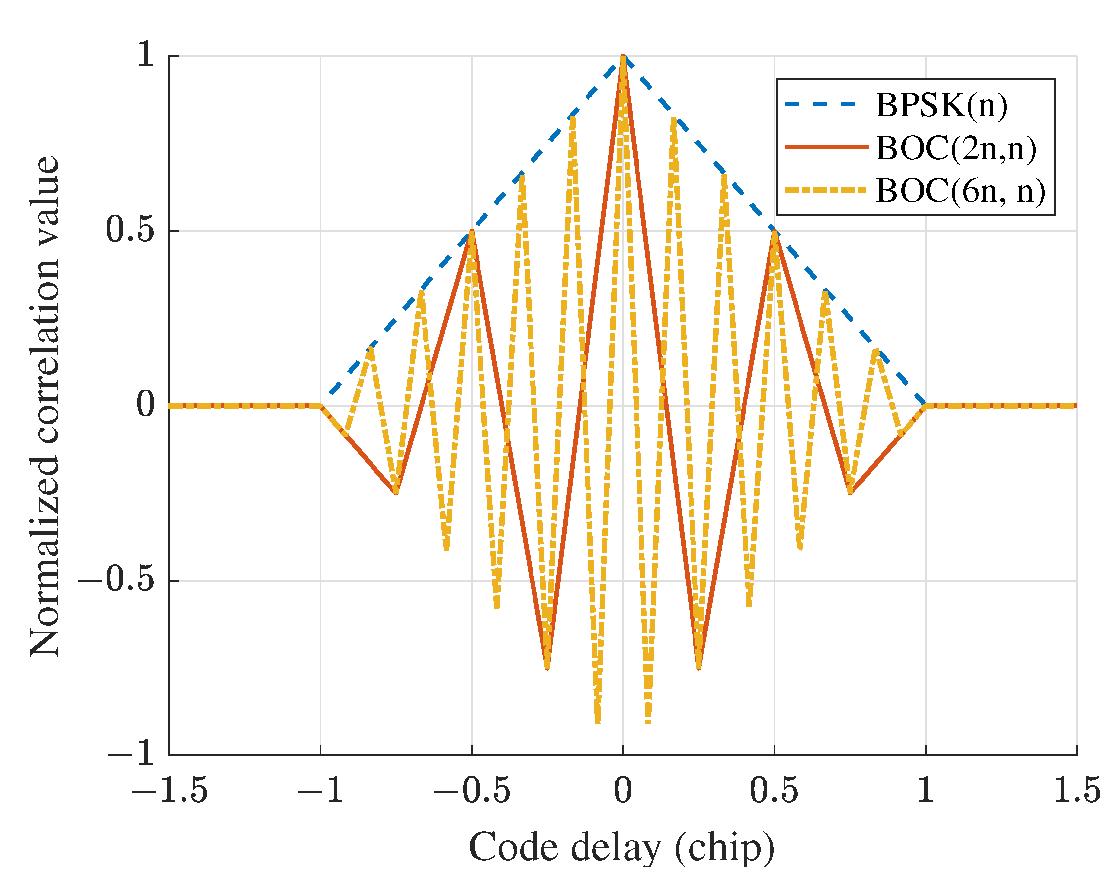
Figure 1 shows the normalized ACF of BPSK(n), BOC(2n, n), and BOC(6n, n) signals. It can be seen from Figure 1 that the ACF of the BOC signal with a higher order has more peaks.
In practice, the signal transmission bandwidth of GNSS satellites is limited. For BOC signals with a high subcarrier frequency, the actual subcarrier emitted by GNSS satellites is not a square wave but approximates a sine wave. For example, the transmission bandwidth for Galileo E1A signal with the BOC(15, 2.5) modulation is 40.96 MHz [26], so the subcarrier harmonics are filtered out at the transmitting end. Moreover, the front-end bandwidth of GNSS receivers is also limited and usually smaller than the GNSS signal transmission bandwidth. The subcarrier of the received BOC signal can be reasonably considered as a sine wave. Therefore, the received BOC signal can be written as:
r d ( t ) = A c ( t τ ) cos ( 2 π f s c t + ϕ ) cos ( 2 π f c t + θ )
where A is the amplitude of the received BOC signal, τ is the propagation delay, f s c is the subcarrier frequency with Doppler, ϕ is the subcarrier phase, f c is the carrier frequency with Doppler, and θ is the carrier phase. For the sake of simplicity, the noise is omitted in Equation (2), which does not affect the following discussions.
Using the trigonometric transformation, Equation (2) can be rewritten as follows:
r d ( t ) = r u ( t ) + r l ( t ) r u ( t ) = A 2 c ( t τ ) cos 2 π ( f c + f s c ) t + ( θ + ϕ ) r l ( t ) = A 2 c ( t τ ) cos 2 π ( f c f s c ) t + ( θ ϕ )
where r u ( t ) is the upper sideband (USB) of the BOC signal, and r l ( t ) is the lower sideband (LSB) of the BOC signal. It can be seen from Equation (3) that both r u ( t ) and r l ( t ) are BPSK-modulated signals.
Equation (3) shows a double-sideband reception model for BOC signals, where the received BOC signal is regarded as the sum of two BPSK signals. Based on this double-sideband signal model, the DBT method jointly processes the two BPSK signals in the USB and LSB to track the BOC signal. Since the ACFs of the two BPSK signals have only one peak, the DBT method solves the tracking ambiguity problem. The DBT loop employs two sets of correlators for the USB and LSB of the BOC signal, so it is compatible with classical GNSS receiver architectures designed for BPSK signals.
Using the DBT loop to track BOC signals can yield three ranging measurements: the code delay, subcarrier phase, and carrier phase. The subcarrier ranging measurement is more accurate than the code ranging measurement, but it has integer ambiguity. In the absence of multipath, code ranging errors are usually less than half of the subcarrier wavelength. Therefore, the subcarrier ambiguity can be fixed by the code ranging measurement to obtain the unambiguous and high-precision pseudo-range:
ρ = ρ s c + round ( ρ c o d e ρ s c λ s c ) λ s c
where ρ s c is the subcarrier ranging measurement, ρ c o d e is the code ranging measurement, and λ s c is the subcarrier wavelength.
In the presence of multipath, code ranging errors may exceed half of the subcarrier wavelength, resulting in an incorrect subcarrier ambiguity solution. Therefore, it is required to reduce the code multipath error to less than half of the subcarrier wavelength. It has been proved that applying the NC technique in the DBT loop can effectively mitigate code multipath errors to meet this requirement [22]. When the subcarrier ambiguity is correctly fixed, the pseudo-range shown in Equation (4) has the same accuracy as the subcarrier ranging measurement.
The accuracy of pseudo-range positioning is usually at the meter level, while centimeter-level positioning applications require high-precision carrier ranging measurements. The carrier phase has integer ambiguity, which needs to be fixed with the pseudo-range. However, the pseudo-range error of the BOC signal, i.e., the subcarrier ranging error, may lead to an incorrect resolution of carrier phase ambiguity. Therefore, it is necessary to design carrier and subcarrier multipath mitigation techniques for BOC signals to improve positioning accuracy.

2.2. Multipath Model for BOC Signals

In practice, the BOC signal is probably reflected or diffracted by obstacles around the GNSS receiver, resulting in multipath signals. Compared with the direct signal, the multipath signal has a longer propagation path. Moreover, the power and carrier Doppler of a multipath signal are usually different from those of the direct signal. The compound signal consisting of the direct signal and multipath signals can be expressed as follows:
r c ( t ) = r d ( t ) + m = 1 M r m ( t )
r m ( t ) = α m A c ( t τ τ m ) cos ( 2 π f s c t + ϕ + ϕ m ) cos 2 π ( f c + f m ) t + θ + θ m
where r d ( t ) is the direct signal shown in Equation (2), r m ( t ) is the m-th multipath signal, M is the number of multipath signals, α m is the multipath relative amplitude, τ m is the multipath relative delay, ϕ m = 2 π f s c τ m is the multipath relative subcarrier phase, f m is the Doppler difference between the direct signal and m-th multipath signal, which is called the fading frequency, and θ m is the multipath relative phase.
The multipath fading frequency is related to the geometric distribution of the satellite, reflecting platform, and GNSS receiver. Fast-varying multipath signals with large fading frequencies will be suppressed by correlators and loop filters of the GNSS receiver [27]. When the reciprocal of the fading frequency is less than the integration time, the multipath signal is completely averaged out and has no effect on the tracking loop. By contrast, slow-varying multipath signals with small fading frequencies severely affect the tracking loop and cause large ranging errors. In conclusion, the slow-varying multipath poses a greater threat to GNSS positioning accuracy than the fast-varying multipath. For a stationary GNSS receiver, the multipath fading frequency is very small, typically less than 1 Hz [28,29]. Most multipath signals received by GNSS receivers used in surveying, monitoring stations, and other low-dynamic scenarios have small fading frequencies and change slowly [30,31]. Therefore, this paper investigates the slow-varying multipath problem for low-dynamic GNSS receivers.
According to the double-sideband reception model for BOC signals, the compound signal shown in Equation (5) can be transformed as follows:
r c ( t ) = r u c ( t ) + r l c ( t ) r u c ( t ) = A 2 c ( t τ ) cos ( 2 π f u t + θ u ) + m = 1 M α m c ( t τ τ m ) cos 2 π ( f u + f m ) t + θ u + θ m + ϕ m r l c ( t ) = A 2 c ( t τ ) cos ( 2 π f l t + θ l ) + m = 1 M α m c ( t τ τ m ) cos 2 π ( f l + f m ) t + θ l + θ m ϕ m
where r u c ( t ) is the USB of the compound signal, r l c ( t ) is the LSB of the compound signal, f u = f c + f s c and f l = f c f s c are the carrier frequencies of the direct USB and LSB signals, respectively, and θ u = θ + ϕ and θ l = θ ϕ are the carrier phases of the USB and LSB direct signals, respectively.
Equation (7) shows that the received BOC signal can be regarded as the sum of USB and LSB signals in the presence of multipath. The BOC multipath signal can be decomposed into two BPSK multipath signals located in the USB and LSB, respectively. Therefore, it is feasible to track the compound BOC signal with the DBT loop. However, multipath signals lead to tracking errors. It is necessary to analyze the effect of multipath on the DBT loop.

2.3. Multipath Effect Analysis for BOC Signals

In the DBT loop, the received BOC signal is first mixed with the in-phase carrier and quadrature-phase carrier generated by the carrier numerically controlled oscillator (NCO), respectively. This process is called the carrier wipe-off. Two zero intermediate-frequency (IF) signals are obtained after wiping off the carrier, which are named the in-phase signal and the quadrature-phase signal, respectively. In correlator channels, the in-phase signal is correlated with local codes generated by the code NCO to calculate in-phase correlation values, and the quadrature-phase signal is correlated with local codes to calculate quadrature-phase correlation values.
The complex correlation functions of the USB and LSB signals can be written as:
R u = A 2 R ( Δ τ d ) + m = 1 M α m R ( Δ τ d τ m ) exp j ( θ m + ϕ m ) exp j ( Δ θ d + Δ ϕ d )
R l = A 2 R ( Δ τ d ) + m = 1 M α m R ( Δ τ d τ m ) exp j ( θ m ϕ m ) exp j ( Δ θ d Δ ϕ d )
where Δ τ d , Δ θ d , and Δ ϕ d are the code delay difference, carrier phase difference, and subcarrier phase difference between the local signal and the direct signal, respectively. R ( · ) denotes the normalized ACF of the spreading code. When the code delay difference between the local signal and the received signal is greater than one chip, the correlation value is very close to zero. The real part of the complex correlation function is the in-phase correlation function, and the imaginary part of the complex correlation function is the quadrature-phase correlation function.
In the absence of multipath, the correlation functions of USB and LSB signals have the same shape. The in-phase correlation function of each single sideband (SSB) signal is an isosceles triangle, as shown by the blue dashed lines in Figure 2. In the DBT loop, each correlator channel for the USB and LSB signals has three correlators, which are denoted as early (E), prompt (P), and late (L), respectively. The spacing between every two adjacent correlators is identical, and the spacing between E and L correlators is called the early-minus-late (EML) spacing.
The EML code discriminator is designed based on the symmetry of the correlation function. However, the symmetry of the correlation function is broken by the multipath as shown in Figure 2, where the multipath relative amplitude is 0.5, the multipath relative carrier phase is π / 6 , and the multipath relative delay is 0.4 chips. Thus, the multipath leads to bias in the EML discrimination output, and the code multipath error is related to the EML spacing. Using narrow EML spacing can effectively reduce the code multipath error, which is the principle of the NC technique.
The P correlation values are used for subcarrier and carrier discrimination in the DBT loop. In the absence of multipath, the quadrature-phase P correlation values of the USB and LSB signals are 0. However, in the presence of multipath, the quadrature-phase P correlation values of the USB and LSB signals are not 0. As a result, the outputs of the carrier and subcarrier discriminators are affected by the multipath.
As shown in Equations (8) and (9), the carrier phase and subcarrier phase are coupled to each other in the USB and LSB correlation values, which implies that the carrier and subcarrier multipath errors interact with each other. Thus, the DBT method subtly combines the USB and LSB correlation values to separate the carrier phase from the subcarrier phase. Specifically, the synthesized correlation function for subcarrier discrimination is calculated as:
R s c = R u + R l = A R ( Δ τ d ) cos ( Δ θ d ) + m = 1 M α m R ( Δ τ d τ m ) cos ( Δ θ d + θ m ) exp ( j ϕ m ) exp ( j Δ ϕ d )
Equation (10) demonstrates that multipath signals lead to a phase rotation of the complex correlation function for subcarrier discrimination. The phase rotation of R s c is the subcarrier multipath error. When there are many multipath signals, it is difficult to derive an analytical formula for the subcarrier multipath error. Assuming that there is only one multipath signal, the subcarrier multipath error of the DBT method can be calculated as:
Δ ϕ M E = arctan α m R ( Δ τ d τ m ) cos ( Δ θ d + θ m ) sin ( ϕ m ) R ( Δ τ d ) cos ( Δ θ d ) + α m R ( Δ τ d τ m ) cos ( Δ θ d + θ m ) cos ( ϕ m )
The synthesized correlation function for carrier discrimination is calculated as:
R c = R u + R l = A R ( Δ τ d ) cos ( Δ ϕ d ) + m = 1 M α m R ( Δ τ d τ m ) cos ( Δ ϕ d + ϕ m ) exp ( j θ m ) exp ( j Δ θ d )
Equation (12) demonstrates that multipath signals lead to a phase rotation of the complex correlation function for carrier discrimination. The phase rotation of R c is the carrier multipath error. Assuming that there is only one multipath signal, the carrier multipath error of the DBT method can be calculated as:
Δ θ M E = arctan α m R ( Δ τ d τ m ) cos ( Δ ϕ d + ϕ m ) sin ( θ m ) R ( Δ τ d ) cos ( Δ ϕ d ) + α m R ( Δ τ d τ m ) cos ( Δ ϕ d + ϕ m ) cos ( θ m )
It is worth noting that the estimated carrier phase Δ θ d and subcarrier phase Δ ϕ d in Equations (11) and (13) contain multipath errors, indicating that the carrier and subcarrier multipath errors affect each other. If multipath mitigation techniques are only used in the SPLL, the subcarrier discrimination output still has deviations due to the indirect effect of carrier multipath errors. Similarly, if multipath mitigation techniques are only used in the PLL, the carrier discrimination output still has deviations due to the indirect effect of subcarrier multipath errors. Therefore, it is required that the multipath mitigation method for BOC signals based on the DBT loop can mitigate both the carrier and subcarrier multipath errors.

3. Materials and Methods

This section proposes a prompt-assisted-offset correlator (PAOC) technique to mitigate carrier and subcarrier multipath errors for BOC signals. Firstly, the principle of the PAOC technique is introduced. Then, the PAOC discriminators and complementary filters are described in detail. Finally, an implementation architecture for applying the PAOC technique in the DBT loop is provided.

3.1. Principle of the PAOC Technique

The multipath signal has a longer propagation delay than the direct signal, implying that the correlation peak of the multipath signal lags behind that of the direct signal. Therefore, the forward offset correlator is less susceptible to the multipath than the prompt correlator. Figure 3 illustrates the effect of a multipath signal with a relative delay of 0.4 chips on different correlators. The quadrature-phase correlation value between the local signal and the direct signal is 0, so the quadrature-phase correlation value of the compound signal is equal to that of the multipath signal. As a result, in Figure 3b, the red and green lines overlap, and the purple and yellow lines overlap. Figure 3 clearly shows that the prompt (P) correlator is affected by the multipath signal, while the offset correlator (OC) with a forward offset of 0.8 chips is not affected by the multipath signal.
In fact, the prompt correlator is affected by multipath signals with relative delays less than 1 chip. The offset correlator with a forward offset of τ o c chips is only affected by multipath signals with relative delays less than 1 τ o c chips. Therefore, using the forward offset correlator instead of the prompt correlator for discrimination can effectively reduce the multipath sensitive area, thus mitigating carrier and subcarrier multipath errors. Furthermore, the multipath performance of the offset correlator improves with the increase of forward offset.
However, as shown in Figure 3, the magnitude of the offset correlator output is smaller than that of the prompt correlator output. In the presence of noise, the SNR of the offset correlator output is poor. Moreover, the thermal noise performance of the offset correlator degrades with the increase of forward offset. As a consequence, using the offset correlator for discrimination requires a compromise between the thermal noise performance and multipath mitigation performance.
It is observed that the prompt correlator output has a high SNR but is susceptible to the multipath. In contrast, the offset correlator output has a low SNR but is less susceptible to the multipath. The prompt correlator and the offset correlator are complementary in terms of both multipath performance and thermal noise performance. Based on this insight, this paper proposes a PAOC technique using the prompt correlator to assist the offset correlator for carrier and subcarrier discrimination. The PAOC technique combines the advantages of the prompt and offset correlators to substantially improve multipath performance with small noise performance loss.

3.2. PAOC Technique for Subcarrier Multipath Mitigation

There are two specially designed subcarrier discriminators in the PAOC technique. One subcarrier discriminator uses the offset correlator and is called the S-OC discriminator. The other subcarrier discriminator uses the prompt correlator and is called the S-P discriminator. The forward offset of the offset correlator relative to the prompt correlator is assumed to be τ o c chips.
The S-OC discriminator is designed as:
Disc ( Δ ϕ o c ) = arctan Q R o c u Q R o c l I R o c u + I R o c l
where I R denotes the in-phase correlator output, Q R denotes the quadrature-phase correlator output, the subscript o c denotes the offset correlator, and the superscripts u and l denote the USB and LSB, respectively.
The S-P discriminator is designed as:
Disc ( Δ ϕ p ) = arctan Q R p u Q R p l I R p u + I R p l
where the subscript p denotes the prompt correlator.
When the multipath relative delay is greater than 1 τ o c chips, the S-OC discriminator output contains no multipath error and can be modeled as:
Δ ϕ o c = Δ ϕ d + ϵ o c
where Δ ϕ d is the subcarrier phase difference between the local signal and the direct signal, and ϵ o c is the S-OC noise error.
The S-P discriminator output contains multipath errors and can be modeled as:
Δ ϕ p = Δ ϕ d + Δ ϕ M E + ϵ p
where Δ ϕ M E is the subcarrier multipath error, and ϵ p is the S-P noise error. Because the prompt correlator output has a higher SNR than the offset correlator, the variance of ϵ p is smaller than that of ϵ o c .
Combining the discriminator outputs shown in Equations (16) and (17), a coarse estimate of the subcarrier multipath error can be obtained as:
Δ ϕ ^ M E = Δ ϕ p Δ ϕ o c = Δ ϕ M E + ϵ p ϵ o c
The subcarrier multipath error estimate Δ ϕ ^ M E shown in Equation (18) is noisy. To obtain a fine estimate of the subcarrier multipath error, a first-order low-pass filter is used to reduce the noise error of Δ ϕ ^ M E . The low-pass filtering process can be expressed as:
Δ ϕ ^ M E F [ k ] = N 1 N Δ ϕ ^ M E F [ k 1 ] + 1 N Δ ϕ ^ M E [ k ]
where N is the smoothing constant of the low-pass filter, and k is the current epoch. The initial value Δ ϕ ^ M E F [ 0 ] can be set as 0.
There is an implicit prerequisite for using the low-pass filter to reduce noise errors, which is that the subcarrier multipath error changes slowly. For a low-dynamic GNSS receiver, the fading frequencies of received multipath signals are usually very small. Therefore, the multipath errors of a static or low-dynamic GNSS receiver change slowly, which allows the low-pass filter to be used.
The smoothing constant N determines the noise error of the filtered estimate Δ ϕ ^ M E F . As the smoothing constant increases, the noise error of Δ ϕ ^ M E F reduces, while the dynamic performance of the GNSS receiver degrades. In practice, the smoothing constant N can be set flexibly as needed. Considering that the fading frequency of multipath signals received by a static or low-dynamic receiver is generally less than 1 Hz, the smoothing time of the low-pass filter is preferably set to be no longer than 1 s. More discussions about the low-pass filter will be given in Section 4.
After low-pass filtering, an accurate estimate of the subcarrier multipath error can be obtained as:
Δ ϕ ^ M E F = Δ ϕ M E + ϵ r e s
where ϵ r e s is the residual noise error with a small variance.
Subtracting the subcarrier multipath error estimate Δ ϕ ^ M E F from the S-P discriminator output Δ ϕ p , an unbiased subcarrier estimate with small noise errors can be obtained as:
Δ ϕ P A O C = Δ ϕ p Δ ϕ ^ M E F = Δ ϕ d + ϵ p ϵ r e s
Equation (21) shows that the PAOC subcarrier estimate Δ ϕ P A O C contains no multipath error. Moreover, the thermal noise error of Δ ϕ P A O C is smaller than that of Δ ϕ o c but lager than that of Δ ϕ p .
The processing described in Equations (18)–(21) can be modeled as a PAOC complementary filter, which is shown in Figure 4. When the smoothing constant is 1, Δ ϕ ^ M E F [ k ] is equal to Δ ϕ ^ M E [ k ] , and the PAOC subcarrier estimate Δ ϕ P A O C is equal to the S-OC discriminator output Δ ϕ o c . That is to say, the OC technique is a special case of the PAOC technique with a smoothing constant of 1.

3.3. PAOC Technique for Carrier Multipath Mitigation

In addition to subcarrier multipath errors, the PAOC technique can also be used to mitigate carrier multipath errors. Similar to the subcarrier discrimination, there are two carrier discriminators in the PAOC technique. One carrier discriminator uses the offset correlator and is called the C-OC discriminator. The other carrier discriminator uses the prompt correlator and is called the C-P discriminator.
The C-OC discriminator is designed as:
Disc ( Δ θ o c ) = arctan Q R o c u + Q R o c l I R o c u + I R o c l
The C-P discriminator is designed as:
Disc ( Δ θ p ) = arctan Q R p u + Q R p l I R p u + I R p l
The outputs of C-OC and C-P discriminators are combined using the PAOC complementary filter shown in Figure 5 to obtain a high-precision carrier estimate Δ θ P A O C without multipath errors. The PAOC complementary filter for the carrier has the same architecture as that for the subcarrier. In practice, the PAOC complementary filters for the carrier and subcarrier can be configured with different parameters if necessary.

3.4. Implementation of the PAOC Technique

Figure 6 shows the implementation architecture of the PAOC technique in the DBT loop, which consists of four main parts: correlator channels, a PAOC-PLL for the carrier, a PAOC-SPLL for the subcarrier, and a DLL for the code. The S-OC discriminator, S-P discriminator, and PAOC complementary filter are implemented in the PAOC-SPLL. The C-OC discriminator, C-P discriminator, and PAOC complementary filter are implemented in the PAOC-PLL.
The correlator channels are divided into correlator channels for the USB signals and correlator channels for the LSB signals. Every correlator channel has four complex correlators, denoted as the offset correlator (OC), early (E), prompt (P), and late (L), respectively. The received BOC signal is correlated with local replicas in correlator channels to obtain correlation values.
The outputs of the OC and P correlators are fed into the PAOC-PLL to estimate the carrier frequency and carrier phase of the received BOC signal. Moreover, the outputs of the OC and P correlators are also fed into the PAOC-SPLL to estimate the subcarrier frequency and subcarrier phase of the received BOC signal. The outputs of the E and L correlators are fed into the DLL to estimate the code rate and code delay of the received BOC signal. It is worth noting that the spacing between the E and L correlators is usually smaller than 0.1 chips, making the code multipath error less than half of the subcarrier wavelength. According to the parameter estimation results, the frequency words of carrier NCOs and code NCOs are adjusted in real-time to generate local replicas, thus forming a closed tracking loop.

4. Performance Evaluation and Results

This section first analyzes the theoretical multipath performance and thermal noise performance of the PAOC technique. Then, some simulation results are presented to compare the PAOC technique with existing multipath mitigation techniques based on the DBT loop.

4.1. Multipath Performance Analysis

The outputs of offset correlators for the USB and LSB signals can be expressed as:
R u o c = A 2 R ( Δ τ d τ o c ) + m = 1 M α m R ( Δ τ d τ o c τ m ) exp j ( θ m + ϕ m ) exp j ( Δ θ d + Δ ϕ d )
R l o c = A 2 R ( Δ τ d τ o c ) + m = 1 M α m R ( Δ τ d τ o c τ m ) exp j ( θ m ϕ m ) exp j ( Δ θ d Δ ϕ d )
The synthesized correlation function used by the S-OC discriminator is calculated as:
R s o c = R u o c + R l o c = A R ( Δ τ d τ o c ) cos ( Δ θ d ) + m = 1 M α m R ( Δ τ d τ o c τ m ) cos ( Δ θ d + θ m ) exp ( j ϕ m ) exp ( j Δ ϕ d )
Multipath signals cause a phase rotation of R s o c , which is the subcarrier multipath error. Assuming that there is only one multipath signal, the subcarrier multipath error of the S-OC discriminator can be calculated as:
Δ ϕ M E = arctan α m R ( Δ τ d τ o c τ m ) cos ( Δ θ d + θ m ) sin ( ϕ m ) R ( Δ τ d τ o c ) cos ( Δ θ d ) + α m R ( Δ τ d τ o c τ m ) cos ( Δ θ d + θ m ) cos ( ϕ m )
When | Δ τ d τ o c τ m | 1 , R ( Δ τ d τ o c τ m ) = 0 . This demonstrates that the S-OC discriminator can eliminate subcarrier multipath errors caused by the multipath signal with a relative delay greater than 1 τ o c chips. The subcarrier multipath error of the S-P discriminator is equal to that of the DBT method, which is given in Equation (11). The PAOC technique subtly combines the outputs of the S-OC and S-P discriminators. Thus, the subcarrier multipath performance of the PAOC technique is the same as that of the S-OC discriminator shown in Equation (27).
The synthesized correlation function used by the C-OC discriminator is calculated as:
R c o c = R u o c + R l o c = A R ( Δ τ d τ o c ) cos ( Δ ϕ d ) + m = 1 M α m R ( Δ τ d τ o c τ m ) cos ( Δ ϕ d + ϕ m ) exp ( j θ m ) exp ( j Δ θ d )
Assuming that there is only one multipath signal, the carrier multipath error of the C-OC discriminator can be calculated as:
Δ θ M E = arctan α m R ( Δ τ d τ o c τ m ) cos ( Δ ϕ d + ϕ m ) sin ( θ m ) R ( Δ τ d τ o c ) cos ( Δ ϕ d ) + α m R ( Δ τ d τ o c τ m ) cos ( Δ ϕ d + ϕ m ) cos ( θ m )
When | Δ τ d τ o c τ m | 1 , R ( Δ τ d τ o c τ m ) = 0 . This demonstrates that the C-OC discriminator can eliminate carrier multipath errors caused by the multipath signal with a relative delay greater than 1 τ o c chips. The carrier multipath error of the C-P discriminator is equal to that of the DBT method, which is given in Equation (13). The PAOC technique subtly combines the outputs of the C-OC and C-P discriminators. Thus, the carrier multipath performance of the PAOC technique is the same as that of the C-OC discriminator shown in Equation (29).
The multipath error envelope (MEE) is a commonly used criterion to evaluate the multipath performance, which shows the maximum error under different multipath relative delays [32]. Equation (27) indicates that the subcarrier multipath error reaches a maximum value when θ m = 0 and π . Equation (29) indicates that the carrier multipath error reaches a maximum value when θ m = ± π / 2 . Figure 7 shows the carrier and subcarrier MEEs of three techniques for the BOC(15, 2.5) signal, where the multipath relative amplitude is 0.5. Two forward offsets are tested for the OC and PAOC techniques, which are 0.5 and 0.8 chips, respectively.
Figure 7 demonstrates that the PAOC technique effectively mitigates carrier and subcarrier multipath errors when the multipath relative delay is greater than 1 τ o c chips. The multipath mitigation performance of the PAOC technique improves with the forward offset. Moreover, the PAOC technique has the same multipath performance as the OC technique with the same forward offset.

4.2. Thermal Noise Performance Analysis

The PAOC technique employs two subcarrier discriminators in the PAOC-SPLL, i.e., the S-OC and S-P discriminators. The S-P discriminator is the same as the subcarrier discriminator used in the original DBT loop. Thus, the thermal noise error of the S-P discriminator output can be expressed as [10]:
σ s p 2 = B S P L L ( 1 0.5 B S P L L T ) C / N 0 β r / 2 + β r / 2 G s ( f ) d f
where B S P L L is the noise bandwidth of the PAOC-SPLL, T is the integration time, C / N 0 is the carrier-to-noise ratio, G s ( f ) is the normalized power spectral density (PSD) of each single sideband of the BOC signal, and β r is the received bandwidth.
The S-OC discriminator uses the offset correlator instead of the prompt correlator. According to the relationship between the offset and prompt correlators, the thermal noise error of the S-OC discriminator output can be calculated as:
σ s o c 2 = B S P L L ( 1 0.5 B S P L L T ) β r / 2 + β r / 2 G s ( f ) d f C / N 0 β r / 2 + β r / 2 G s ( f ) cos ( 2 π f τ o c ) d f 2
The derivation of Equation (31) is given in Appendix A.
The outputs of the S-P and S-OC discriminators are combined in the subcarrier PAOC complementary filter to obtain an accurate subcarrier estimate Δ ϕ P A O C . Therefore, the noise variance σ s P A O C 2 of the PAOC subcarrier estimate Δ ϕ P A O C is between σ s p 2 and σ s o c 2 . When the smoothing constant of the subcarrier PAOC complementary filter is one, the PAOC technique degenerates to the OC technique, and σ s P A O C 2 is equal to σ s o c 2 . As the smoothing constant increases, σ s P A O C 2 gradually approaches σ s p 2 .
The PAOC technique employs two carrier discriminators in the PAOC-PLL, i.e., the C-OC and C-P discriminators. The C-P discriminator is the same as the carrier discriminator used in the original DBT loop. Thus, the thermal noise error of the C-P discriminator output can be expressed as [10]:
σ c p 2 = B P L L ( 1 0.5 B P L L T ) C / N 0 β r / 2 + β r / 2 G s ( f ) d f
where B P L L is the noise bandwidth of the PAOC-PLL.
The C-OC discriminator uses the offset correlator instead of the prompt correlator. According to the relationship between the offset and prompt correlators, the thermal noise error of the C-OC discriminator output can be calculated as:
σ c o c 2 = B P L L ( 1 0.5 B P L L T ) β r / 2 + β r / 2 G s ( f ) d f C / N 0 β r / 2 + β r / 2 G s ( f ) cos ( 2 π f τ o c T c ) d f 2
The derivation of Equation (33) is given in Appendix A.
The outputs of the C-P and C-OC discriminators are combined in the carrier PAOC complementary filter to obtain an accurate carrier estimate Δ θ P A O C . Therefore, the noise variance σ c P A O C 2 of the PAOC carrier estimate Δ θ P A O C is between σ c p 2 and σ c o c 2 . When the smoothing constant of the carrier PAOC complementary filter is one, σ c P A O C 2 is equal to σ c o c 2 . As the smoothing constant increases, σ c P A O C 2 gradually approaches σ c p 2 .
Figure 8 shows the subcarrier and carrier noise errors of three techniques for the BOC(15, 2.5) signal, where the noise bandwidths of the SPLL and the PLL are 1 Hz and 10 Hz, respectively. With the identical forward offset, the PAOC technique has better noise performance than the OC technique. As the smoothing constant N increases, thermal noise errors of the PAOC technique gradually decrease and approach those of the DBT method.
The tracking threshold of the PLL usually requires the standard deviation of the carrier phase error to be no more than 15. Figure 8b demonstrates that the application of the OC technique in the PLL may cause the tracking loop to lose lock. Compared with the OC technique, the PAOC technique can greatly reduce the risk of losing lock.

4.3. Simulation Results

In the following experiments, four methods are compared in terms of thermal noise performance and multipath performance, which are shown in Table 1. The first method is the original DBT, where both the SPLL and the PLL use prompt correlators. The second method is called the OC-P, where the SPLL uses the OC technique, and the PLL uses the prompt correlator. The third method is called the OC-OC, where both the PLL and the SPLL use the OC technique. The fourth method is called the PAOC-PAOC, where both the PLL and the SPLL use the PAOC technique. The first two methods, DBT [10] and OC-P [22], are old methods that have been proposed before. The last two methods, OC-OC and PAOC-PAOC, are new methods proposed in this paper for the first time.
A GNSS receiver equipped with the DBT loop was developed to evaluate the performance of various methods. In all subsequent experiments, the common parameters are configured as shown in Table 2: the receiver front-end bandwidth is 40.96 MHz, the EML spacing is 0.1 chips, the integration time is 10 ms, the noise bandwidths of the DLL, SPLL, and PLL are 1 Hz, 1 Hz, and 10 Hz, respectively, C / N 0 of the direct signal is 42 dB-Hz, and the multipath relative amplitude is 0.5.

4.3.1. Parameter Configuration of the OC and PAOC Techniques

The forward offset τ o c has a great impact on the performance of the OC and PAOC techniques. Figure 9 shows the carrier and subcarrier noise errors of four methods for the BOC(15, 2.5) signal without multipath, where the smoothing constant of the PAOC technique is 20. The OC-P and OC-OC methods have the same subcarrier noise performance because they use the same offset correlator in the SPLL. The OC-P and DBT methods have the same carrier noise performance because they use the same prompt correlator in the PLL. The thermal noise error increases with the forward offset for both the OC and PAOC techniques. Moreover, the thermal noise error of the PAOC technique is much smaller than that of the OC technique with the same forward offset.
Thermal noise performance affects the tracking stability, which is the primary consideration for GNSS receivers. It is fair to compare the multipath performance of the OC and PAOC techniques under the same thermal noise performance. Therefore, in the subsequent experiments, the forward offset of the OC technique is set as 0.5 chips, and the forward offset of the PAOC technique is set as 0.8 chips with a smoothing constant of 20. The integration time is 10 ms, so a smoothing constant of 20 means that the smoothing time is 0.2 s.

4.3.2. Static Multipath Scenarios

In practice, ranging errors include the noise error and multipath error. Moreover, multipath signals lead to variations in the SNR, thereby affecting the thermal noise error. It is difficult to separate the noise error from the multipath error. Thus, the root-mean-square error (RMSE) is used to evaluate the ranging performance of the four methods.
According to Equations (27) and (29), when the multipath relative phase is 0 and π , the subcarrier multipath error reaches its maximum value, while the carrier multipath error is almost 0. Figure 10 shows the RMSE envelop of the four methods for the BOC(15, 2.5) signal when the multipath relative phase is 0 and π . The subcarrier RMSE varies with multipath relative delay in Figure 10a due to the multipath error.
According to Equations (13) and (29), the carrier multipath errors of all four methods are 0 when the multipath relative phase θ m is 0 and π . Therefore, the carrier errors shown in Figure 10b are noise errors. Since the PAOC technique has thermal noise performance loss compared with using the prompt correlator, the carrier RMSE of the PAOC-PAOC method in Figure 10b is larger than that of the OC-P and DBT methods. Moreover, the carrier RMSE varies with multipath relative delay in Figure 10b because the SNR is affected by multipath.
According to Equations (27) and (29), when the multipath relative phase is ± π / 2 , the subcarrier multipath error reaches its minimum value, while the carrier multipath error reaches its maximum value. Figure 11 shows the RMSE envelop of four methods for the BOC(15, 2.5) signal when the multipath relative phase is ± π / 2 .
When the multipath relative delay is greater than 1 chip, there is only thermal noise error and no multipath error in the RMSE. When the multipath relative delay is less than 1 chip, the RMSE of the DBT method contains both thermal noise error and multipath error. Comparing the RMSE in the two cases, it can be found that the multipath error is significantly larger than the thermal noise error. Moreover, Figure 10 and Figure 11 show that the PAOC-PAOC method has better multipath mitigation performance than the other three methods.
Both OC-P and OC-OC methods use the OC technique with the same forward offset in the SPLL, which suggests that they have the same subcarrier multipath performance. However, Figure 11a shows that the subcarrier RMSE of the OC-P method is greater than that of the OC-OC method. This is because the OC-P and OC-OC methods use different techniques in the PLL, and the carrier error indirectly affects the subcarrier error. Figure 11b shows that the carrier RMSE of the OC-P method is greater than that of the OC-OC method. The OC-OC method using the OC technique in the PLL not only directly improves the carrier multipath performance, but also indirectly improves the subcarrier multipath performance. Therefore, it is desirable to use multipath mitigation techniques in both the PLL and the SPLL to improve multipath performance.
The area enclosed by the RMSE envelop can reflect the average ranging performance of the multipath mitigation methods, which is calculated as:
A r e a ( τ m a x ) = 0 τ m a x R M S E ( τ m ) d τ m
where τ m a x is the maximum multipath relative delay. Considering that multipath signals with relative delays greater than 1 chip do not cause multipath errors, τ m a x is set to 1.2 chips.
Table 3 shows the area enclosed by RMSE envelopes of the four methods. When the multipath relative phase is ± π / 2 , the PAOC-PAOC method has the smallest subcarrier and carrier RMSE area. When the multipath relative phase is 0 and π , the PAOC-PAOC method has the smallest subcarrier RMSE area but has a large carrier RMSE area. This is because the PAOC technique has thermal noise performance loss compared with using the prompt correlator. When the multipath relative phase is 0 and π , the carrier multipath error is almost 0, and the carrier RMSE contains only the thermal noise error. Since the PAOC-PAOC method greatly improves multipath performance, the thermal noise performance loss is acceptable.

4.3.3. Dynamic Multipath Scenario

To further verify the ranging performance of the PAOC technique in the dynamic multi-path scenario, a slow-varying multipath signal is simulated. Figure 12 illustrates the variation of this multipath signal.
Figure 13 shows the ranging errors of the four methods for the BOC(15, 2.5) signal in the dynamic multipath scenario. The carrier and subcarrier ranging errors of the PAOC-PAOC method are always smaller than those of the other three methods. Table 4 shows the ranging errors of the four methods in the dynamic multipath scenario. Both the RMSE and maximum ranging error of the PAOC-PAOC method are much smaller than those of the other three methods. In summary, the PAOC-PAOC method can effectively reduce the carrier and subcarrier ranging errors caused by the low-dynamic multipath.

5. Discussion

The PAOC technique could be regarded as an improved OC technique. The original OC technique only uses the forward offset correlator for discrimination. As the forward offset increases, the multipath mitigation performance of the OC technique improves, while its thermal noise performance deteriorates. To resolve this contradiction, the PAOC technique uses the prompt correlator to assist the offset correlator for discrimination. Specifically, a PAOC complementary filter is designed to combine the discrimination results of the prompt and offset correlators. Compared with the original OC technique, the PAOC technique has less thermal noise loss and reduces the risk of losing lock in the tracking loop. This suggests that the PAOC technique can use a larger forward offset to obtain better multipath performance in practice.
The PAOC technique is more suitable for low-dynamic and stationary GNSS receivers. Experimental results in this paper show that the PAOC technique with a smoothing time of 0.2 s can effectively reduce thermal noise errors. Using a longer smoothing time can further reduce thermal noise errors, but the smoothing time is preferably no more than 1 s to maintain the dynamic performance. In practice, both the forward offset and smoothing time of the PAOC technique can be flexibly configured.
The PAOC technique is easy to implement in existing GNSS receivers and has low computational complexity. Compared with the OC technique, the PAOC technique adds a complementary filter. The calculation rate of the complementary filter is typically between 50 and 1000 Hz, while the calculation rate of correlators is equal to the signal sampling rate, which is usually greater than 10 MHz for BOC signals. Therefore, the calculation amount of correlators is much larger than that of the complementary filter. Compared with the DBT method, the PAOC technique additionally uses two offset correlators. Considering that the DBT method employs eight correlators, using the PAOC technique in the DBT loop increases the computational burden by about 25%.
As an internal-receiver multipath mitigation technique, the PAOC technique proposed in this paper does not use additional sensors. If auxiliary sensors, such as the inertial navigation systems, are available, the receiver status can be better detected so that appropriate parameters can be selected for the PAOC technique to optimize the multipath and noise performance. Moreover, the PAOC technique can be used together with pre-receiver and post-processing techniques to further improve the multipath performance of GNSS receivers.

6. Conclusions

This paper proposes a new multipath mitigation technique named PAOC for BOC signals. Theoretical analysis and experimental results demonstrate that the PAOC technique significantly improves multipath performance with small noise performance loss. Moreover, it is found that subcarrier and carrier multipath errors can affect each other due to the coupling effect between the PLL and the SPLL. Therefore, this paper proposes to apply the PAOC technique in both the PLL and the SPLL of the DBT loop to mitigate carrier and subcarrier multipath simultaneously. Compared with existing multipath mitigation methods for BOC signals based on the DBT loop, the proposed method has better carrier and subcarrier multipath performance.

Author Contributions

Conceptualization, methodology, software, data analysis, investigation, and original draft preparation, review and editing, Z.T.; methodology and manuscript review, X.C.; supervision, project administration, and funding acquisition, M.L. All authors have read and agreed to the published version of the manuscript.

Funding

This research was funded by the National Key R&D Program of China under Grant No. 2021YFA0716603.

Data Availability Statement

Not applicable.

Conflicts of Interest

The authors declare no conflict of interest.

Abbreviations

The following abbreviations are used in this manuscript:
ACFAuto-Correlation Function
BOCBinary Offset Carrier
BPSKBinary Phase-Shift Keying
DBTDual BPSK Tracking
DLLDelay Lock Loop
EMLEarly-Minus-Late
GNSSGlobal Navigation Satellite System
LSBLower Sideband
MEEMultipath Error Envelope
NCNarrow Correlation
NCONumerically Controlled Oscillator
OCOffset Correlator
PAOCPrompt-Assisted-Offset Correlator
PLLPhase Lock Loop
PSDPower Spectral Density
RMSERoot-Mean-Square Error
SNRSignal-to-Noise Ratio
SPLLSubcarrier Phase Lock Loop
USBUpper Sideband

Appendix A. Thermal Noise Performance Analysis for the S-OC and C-OC Discriminators

Assuming that the code delay τ is accurately estimated, the local USB and LSB signals used in the offset correlator can be written as:
r ^ u o c ( t ) = c ( t τ + τ o c ) exp ( j ( θ ^ + ϕ ^ ) ) )
r ^ l o c ( t ) = c ( t τ + τ o c ) exp ( j ( θ ^ ϕ ^ ) ) )
where τ o c is the forward offset of the offset correlator, θ ^ is the local carrier phase, and ϕ ^ is the local subcarrier phase.
Ignoring the noise, the received baseband signal that is fed into the offset correlator for the USB signal can be written as:
s u ( t ) = A 2 c ( t τ ) ( exp ( j ( θ + ϕ ) ) + exp ( j ( 4 π f s c t + θ ϕ ) )
The offset correlation value for the USB signal without noise can be calculated as:
S u o c = 1 T ( k 1 ) T k T r ^ u o c ( t ) s u ( t ) d t = A 2 exp ( j ( Δ θ + Δ ϕ ) ) β r / 2 + β r / 2 G s ( f ) cos ( 2 π f τ o c ) d f
where T is the integration time, Δ θ = θ θ ^ is the carrier phase error, Δ ϕ = ϕ ϕ ^ is the subcarrier phase error, β r is receiver bandwidth, and G s ( f ) is the normalized power spectral density (PSD) of either sideband of the BOC signal.
Considering the noise, the offset correlator output for the USB signal is written as:
R u o c = S u o c + N u o c
where N u o c is the noise component and is calculated as:
N u o c = 1 T ( k 1 ) T k T r ^ u o c ( t ) n ( t ) d t
where n ( t ) is the zero-mean Gaussian white noise with a PSD of N 0 .
The mean value of N u o c is 0, and the variance of N u o c is calculated as:
var ( N u o c ) = E | N u o c | 2 = N 0 T β r / 2 + β r / 2 G s ( f ) d f
Ignoring the noise, the received baseband signal that is fed into the offset correlator for the LSB signal can be written as:
s l ( t ) = A 2 c ( t τ ) ( exp ( j ( θ ϕ ) ) + exp ( j ( 4 π f s c t + θ + ϕ ) )
The offset correlation value for the LSB signal without noise can be calculated as:
S l o c = 1 T ( k 1 ) T k T r ^ l o c ( t ) s l ( t ) d t = A 2 exp ( j ( Δ θ Δ ϕ ) ) β r / 2 + β r / 2 G s ( f ) cos ( 2 π f τ o c ) d f
Considering the noise, the offset correlator output for the LSB signal is written as:
R l o c = S l o c + N l o c
where the mean value of N l o c is 0, and the variance of N l o c is equal to var ( N u o c ) .
According to Equation (26), the offset correlator outputs for USB and LSB signals are combined to obtain a subcarrier correlation value:
R s o c = R u o c + R l o c
The mean value of the real part of R s o c is calculated as:
E Re R s o c = Re S u o c + S l o c = A cos ( Δ ϕ ) cos ( Δ θ ) β r / 2 + β r / 2 G s ( f ) cos ( 2 π f τ o c ) d f
The mean value of the imaginary part of R s o c is calculated as:
E Im R s o c = Im S u o c + S l o c = A sin ( Δ ϕ ) cos ( Δ θ ) β r / 2 + β r / 2 G s ( f ) cos ( 2 π f τ o c ) d f
It can be found that
E Im R s o c E Re R s o c = tan ( Δ ϕ )
Thus, the S-OC discriminator is designed as:
Disc ( Δ ϕ ) = arctan Im R s o c Re R s o c
When the carrier phase error Δ θ and subcarrier phase error Δ ϕ are very close to 0, Equation (A15) can be approximated as:
Disc ( Δ ϕ ) Im R s o c Re R s o c Im N u o c N l o c A β r / 2 + β r / 2 G s ( f ) cos ( 2 π f τ o c ) d f
The variance of the imaginary part of R s o c is calculated as:
var ( Im R s o c ) = var ( Im N u o c N l o c ) = N 0 T β r / 2 + β r / 2 G s ( f ) d f
Thus, the variance of estimated Δ ϕ can be calculated as:
var ( Δ ϕ ) = β r / 2 + β r / 2 G s ( f ) d f 2 T C / N 0 β r / 2 + β r / 2 G s ( f ) cos ( 2 π f τ o c ) d f 2
where C = A 2 / 2 is the carrier power.
In the SPLL, the output of the S-OC discriminator is filtered to obtain a smoothed subcarrier phase estimate, whose variance can be expressed as [33]:
σ s o c 2 = 2 B S P L L T ( 1 0.5 B S P L L T ) var ( Δ ϕ ) = B S P L L ( 1 0.5 B S P L L T ) β r / 2 + β r / 2 G s ( f ) d f C / N 0 β r / 2 + β r / 2 G s ( f ) cos ( 2 π f τ o c ) d f 2
where B S P L L is the noise bandwidth of the SPLL.
According to Equation (28), the offset correlator outputs for USB and LSB signals are combined to obtain a carrier correlation value:
R c o c = R u o c + R l o c
The mean value of the real part of R c o c is calculated as:
E Re R c o c = Re S u o c + S l o c = A cos ( Δ θ ) cos ( Δ ϕ ) β r / 2 + β r / 2 G s ( f ) cos ( 2 π f τ o c ) d f
The mean value of the imaginary part of R c o c can be calculated as:
E Im R c o c = Im S u o c + S l o c = A sin ( Δ θ ) cos ( Δ ϕ ) β r / 2 + β r / 2 G s ( f ) cos ( 2 π f τ o c ) d f
It can be found that
E Im R c o c E Re R c o c = tan ( Δ θ )
Thus, the C-OC discriminator is designed as:
Disc ( Δ θ ) = arctan Im R c o c Re R c o c
When the carrier phase error Δ θ and subcarrier phase error Δ ϕ are very close to 0, Equation (A24) can be approximated as:
Disc ( Δ θ ) Im R c o c Re R c o c Im N u o c + N l o c A β r / 2 + β r / 2 G s ( f ) cos ( 2 π f τ o c ) d f
The variance of the imaginary part of R c o c is calculated as:
var ( Im R c o c ) = var ( Im N u o c + N l o c ) = N 0 T β r / 2 + β r / 2 G s ( f ) d f
Thus, the variance of estimated Δ θ can be calculated as:
var ( Δ θ ) = β r / 2 + β r / 2 G s ( f ) d f 2 T C / N 0 β r / 2 + β r / 2 G s ( f ) cos ( 2 π f τ o c ) d f 2
In the PLL, the output of the C-OC discriminator is filtered to obtain a smoothed carrier phase estimate, whose variance can be expressed as [33]:
σ c o c 2 = 2 B P L L T ( 1 0.5 B P L L T ) var ( Δ θ ) = B P L L ( 1 0.5 B P L L T ) β r / 2 + β r / 2 G s ( f ) d f C / N 0 β r / 2 + β r / 2 G s ( f ) cos ( 2 π f τ o c ) d f 2
where B P L L is the noise bandwidth of the PLL.

References

  1. Kaplan, E.D.; Hegarty, C. Understanding GPS/GNSS: Principles and Applications; Artech House: Norwood, MA, USA, 2017. [Google Scholar]
  2. Pullen, S.; Enge, P.; Lee, J. Local-area differential GNSS architectures optimized to support unmanned aerial vehicles (UAVs). In Proceedings of the International Technical Meeting of the Institute of Navigation (ION ITM 2013), San Diego, CA, USA, 28–30 January 2013; pp. 28–30. [Google Scholar]
  3. AVILA-RODRIGUEZ, J.A.; Hein, G.W.; Wallner, S.; ISSLER, J.L.; Ries, L.; Lestarquit, L.; LATOUR, A.d.; Godet, J.; Bastide, F.; Pratt, T.; et al. The MBOC modulation: The final touch to the Galileo frequency and signal plan. Navigation 2008, 55, 15–28. [Google Scholar] [CrossRef]
  4. Hein, G.W. Status, perspectives and trends of satellite navigation. Satell. Navig. 2020, 1, 22. [Google Scholar] [CrossRef] [PubMed]
  5. Betz, J.W. The offset carrier modulation for GPS modernization. In Proceedings of the 1999 National Technical Meeting of The Institute of Navigation, San Diego, CA, USA, 25–27 January 1999; pp. 639–648. [Google Scholar]
  6. Betz, J.W. Binary Offset Carrier Modulations for Radionavigation. Navigation 2001, 48, 227–246. [Google Scholar] [CrossRef]
  7. Hodgart, S.; Blunt, P. Dual estimate receiver of binary offset carrier modulated signals for global navigation satellite systems. Electron. Lett. 2007, 43, 877–878. [Google Scholar] [CrossRef]
  8. Borio, D. Double phase estimator: New unambiguous binary offset carrier tracking algorithm. IET Radar Sonar Navig. 2014, 8, 729–741. [Google Scholar] [CrossRef]
  9. Zhu, Y.; Cui, X.; Lu, M. Dual binary phase-shift keying tracking method for Galileo E5 AltBOC(15,10) signal and its thermal noise performance. IET Radar Sonar Navig. 2015, 9, 669–680. [Google Scholar] [CrossRef]
  10. Zhu, Y.; Cui, X.; Lu, M. A unified tracking structure for both single-band and dual-band processing of high-order BOC signal. In Proceedings of the 28th International Technical Meeting of the Satellite Division of the Institute of Navigation (ION GNSS+ 2015), Tampa, FL, USA, 14–18 September 2015; pp. 3638–3647. [Google Scholar]
  11. Qin, H.; Xue, X.; Yang, Q. GNSS multipath estimation and mitigation based on particle filter. IET Radar Sonar Navig. 2019, 13, 1588–1596. [Google Scholar] [CrossRef]
  12. Townsend, B.R.; Fenton, P.C.; Van Dierendonck, K.J.; Van Nee, D.R. Performance evaluation of the multipath estimating delay lock loop. Navigation 1995, 42, 502–514. [Google Scholar] [CrossRef]
  13. Van Dierendonck, A.; Fenton, P.; Ford, T. Theory and performance of narrow correlator spacing in a GPS receiver. Navigation 1992, 39, 265–283. [Google Scholar] [CrossRef]
  14. McGraw, G.A.; Braasch, M.S. GNSS multipath mitigation using gated and high resolution correlator concepts. In Proceedings of the 1999 National Technical Meeting of the Institute of Navigation, San Diego, CA, USA, 25–27 January 1999; pp. 333–342. [Google Scholar]
  15. Veitsel, V.A.; Zhdanov, A.V.; Zhodzishsky, M.I. The mitigation of multipath errors by strobe correlators in GPS/GLONASS receivers. GPS Solut. 1998, 2, 38–45. [Google Scholar] [CrossRef]
  16. Nunes, F.D.; Sousa, F.M.; Leitao, J.M. Gating functions for multipath mitigation in GNSS BOC signals. IEEE Trans. Aerosp. Electron. Syst. 2007, 43, 951–964. [Google Scholar] [CrossRef]
  17. Wu, J.; Dempster, A.G. “BOC-Gated-PRN” A Multipath Mitigation Technique for BOC (n, n) Waveforms. IEEE Trans. Aerosp. Electron. Syst. 2011, 47, 1136–1153. [Google Scholar] [CrossRef]
  18. Irsigler, M.; Eissfeller, B. Comparison of multipath mitigation techniques with consideration of future signal structures. In Proceedings of the 16th International Technical Meeting of the Satellite Division of The Institute of Navigation (ION GPS/GNSS 2003), Portland, OR, USA, 9–12 September 2003; pp. 2584–2592. [Google Scholar]
  19. Jovanovic, A.; Tawk, Y.; Botteron, C.; Farine, P.A. Multipath mitigation techniques for CBOC, TMBOC and AltBOC signals using advanced correlators architectures. In Proceedings of the IEEE/ION Position, Location and Navigation Symposium, Indian Wells, CA, USA, 4–6 May 2010; pp. 1127–1136. [Google Scholar]
  20. Hodgart, M.; Blunt, P.; Unwin, M. The optimal dual estimate solution for robust tracking of binary offset carrier (BOC) modulation. In Proceedings of the 20th International Technical Meeting of the Satellite Division of The Institute of Navigation (ION GNSS 2007), Fort Worth, TX, USA, 25–28 September 2007; pp. 1017–1027. [Google Scholar]
  21. Gao, Y.; Yao, Z.; Zhu, Y.; Lu, M. A two-dimension tracking based multipath mitigation method for BOC signals. In Proceedings of the 2014 International Technical Meeting of The Institute of Navigation, San Diego, CA, USA, 27–29 January 2014; pp. 876–883. [Google Scholar]
  22. Wang, C.; Cui, X.; Zhu, Y.; Lu, M. Multipath Mitigation Methods of BOC-family Signals Based on Dual BPSK Tracking Techniques. IEEE Trans. Aerosp. Electron. Syst. 2022, 58, 4824–4834. [Google Scholar] [CrossRef]
  23. Chengtao, X.; Zhe, L.; Xiaomei, T.; Feixue, W. Strobe double phase estimator: A multipath mitigating technique for BOC signal in GNSS based on double phase estimator. Int. J. Satell. Commun. Netw. 2017, 35, 249–261. [Google Scholar] [CrossRef]
  24. Bétaille, D.; Maenpa, J.; Euler, H.J.; Cross, P. A new approach to GPS phase multipath mitigation. In Proceedings of the 2003 National Technical Meeting of The Institute of Navigation, Anaheim, CA, USA, 22–24 January 2003; pp. 243–253. [Google Scholar]
  25. Bétaille, D.; Maenpa, J.; Euler, H.J.; Cross, P. Overcoming the limitations of the phase multipath mitigation window. In Proceedings of the 16th International Technical Meeting of the Satellite Division of The Institute of Navigation (ION GPS/GNSS 2003), Portland, OR, USA, 9–12 September 2003; pp. 2102–2111. [Google Scholar]
  26. European Commission, Directorate-General for Internal Market, Industry, Entrepreneurship and SMEs. European GNSS (Galileo) Open Service Signal in Space Interface Control Document; Office for Official Publications of the European Communities: Luxembourg, 2021. [Google Scholar]
  27. Kelly, J.M.; Braasch, M.S.; DiBenedetto, M.F. Characterization of the effects of high multipath phase rates in GPS. GPS Solut. 2003, 7, 5–15. [Google Scholar] [CrossRef]
  28. Wang, Y.; Chen, X.; Liu, P. Statistical multipath model based on experimental GNSS data in static urban canyon environment. Sensors 2018, 18, 1149. [Google Scholar] [CrossRef] [PubMed]
  29. Chen, X. Statistical multipath model comparative analysis of different GNSS orbits in static urban canyon environment. Adv. Space Res. 2018, 62, 1034–1048. [Google Scholar] [CrossRef]
  30. Irsigler, M. Characterization of multipath phase rates in different multipath environments. GPS Solut. 2010, 14, 305–317. [Google Scholar] [CrossRef]
  31. Xie, P.; Petovello, M.G. Measuring GNSS multipath distributions in urban canyon environments. IEEE Trans. Instrum. Meas. 2014, 64, 366–377. [Google Scholar]
  32. Irsigler, M.; Avila-Rodriguez, J.A.; Hein, G.W. Criteria for GNSS multipath performance assessment. In Proceedings of the 18th International Technical Meeting of the Satellite Division of The Institute of Navigation (ION GNSS 2005), Long Beach, CA, USA, 13–16 September 2005; pp. 2166–2177. [Google Scholar]
  33. Betz, J.W.; Kolodziejski, K.R. Generalized Theory of Code Tracking with an Early-Late Discriminator Part I: Lower Bound and Coherent Processing. IEEE Trans. Aerosp. Electron. Syst. 2009, 45, 1538–1556. [Google Scholar] [CrossRef]
Figure 1. Normalized auto-correlation functions of BPSK(n), BOC(2n,n), and BOC(6n,n) signals.
Remotesensing 15 00937 g001
Figure 2. Normalized correlation functions for each single sideband of the BOC(15, 2.5) signal, where E, P, and L denote early, prompt, and late correlators, respectively: (a) in-phase correlation functions; (b) quadrature-phase correlation functions.
Remotesensing 15 00937 g002
Figure 3. Schematic diagram of the multipath effect on the offset correlator (OC) and the prompt (P) correlator: (a) in-phase correlation functions; (b) quadrature-phase correlation functions.
Remotesensing 15 00937 g003
Figure 4. Schematic diagram of the PAOC technique for subcarrier multipath mitigation.
Remotesensing 15 00937 g004
Figure 5. Schematic diagram of the PAOC technique for carrier multipath mitigation.
Remotesensing 15 00937 g005
Figure 6. Implementation architecture of the PAOC technique in the DBT loop for BOC signals.
Remotesensing 15 00937 g006
Figure 7. MEEs of the DBT, OC, and PAOC techniques for the BOC(15, 2.5) signal with a bandwidth of 40.96 MHz: (a) subcarrier MEE; (b) carrier MEE.
Remotesensing 15 00937 g007
Figure 8. Tracking jitters of the DBT, OC, and PAOC techniques for the BOC (15, 2.5) signal with a bandwidth of 40.96 MHz: (a) subcarrier noise error; (b) carrier noise error.
Remotesensing 15 00937 g008
Figure 9. Tracking jitters of various methods for the BOC(15, 2.5) signal without multipath: (a) subcarrier noise error; (b) carrier noise error.
Remotesensing 15 00937 g009
Figure 10. RMSE envelop of various methods for the BOC(15, 2.5) signal, where the multipath relative phase is 0 and π : (a) subcarrier RMSE; (b) carrier RMSE.
Remotesensing 15 00937 g010
Figure 11. RMSE envelop of various methods for the BOC(15, 2.5) signal, where the multipath relative phase is ± π / 2 : (a) subcarrier RMSE; (b) carrier RMSE.
Remotesensing 15 00937 g011
Figure 12. Variations of the multipath relative delay.
Remotesensing 15 00937 g012
Figure 13. Ranging errors of various methods for the BOC(15, 2.5) signal in the dynamic multipath scenario: (a) subcarrier ranging error; (b) carrier ranging error.
Remotesensing 15 00937 g013
Table 1. Configurations of the four tracking methods for BOC signals.
MethodDLLSPLLPLL
DBTNarrow correlationPrompt correlatorPrompt correlator
OC-PNarrow correlationOffset correlatorPrompt correlator
OC-OCNarrow correlationOffset correlatorOffset correlator
PAOC-PAOCNarrow correlationPAOCPAOC
Table 2. Common parameters for all subsequent simulations.
ParameterValue
Front-end bandwidth40.96 MHz
Integration time10 ms
EML spacing0.1 chips
DLL bandwidth1 Hz
SPLL bandwidth1 Hz
PLL bandwidth10 Hz
C / N 0 of the direct signal42 dB-Hz
Multipath relative amplitude0.5
Table 3. Area enclosed by RMSE envelopes of the four methods for the BOC(15, 2.5) signal.
MethodSubcarrier ( θ m = 0 & π )Subcarrier ( θ m = ± π / 2 )Carrier ( θ m = 0 & π )Carrier ( θ m = ± π / 2 )
DBT0.510.091.968.84
OC-P0.280.081.988.72
OC-OC0.280.073.776.47
PAOC-PAOC0.150.054.044.71
θm denotes the multipath relative phase.
Table 4. Ranging errors of the four methods for the BOC(15, 2.5) signal in the dynamic multipath scenario.
MethodSubcarrier RMSESubcarrier Maximum ErrorCarrier
RMSE
Carrier Maximum Error
DBT0.49 m1.01 m9.65°23.06°
OC-P0.29 m0.77 m9.63°23.98°
OC-OC0.28 m0.76 m6.70°16.97°
PAOC-PAOC0.11 m0.41 m3.92°14.47°
Disclaimer/Publisher’s Note: The statements, opinions and data contained in all publications are solely those of the individual author(s) and contributor(s) and not of MDPI and/or the editor(s). MDPI and/or the editor(s) disclaim responsibility for any injury to people or property resulting from any ideas, methods, instructions or products referred to in the content.

