Communication

Analysis of a Low-Earth Orbit Satellite Downlink Considering Antenna Radiation Patterns and Space Environment in Interference Situations

1
Department of Electronic and Electrical Engineering, Hongik University, Seoul 04066, Republic of Korea
2
Department of AI Convergence Network, Ajou University, Suwon, Gyeonggi-do 16499, Republic of Korea
3
Radar and EW Technology Center Agency for Defense Development, Daejeon 34186, Republic of Korea
4
Department of Electrical and Computer Engineering, Ajou University, Gyeonggi-do 16499, Republic of Korea
*
Author to whom correspondence should be addressed.
Remote Sens. 2023, 15(7), 1748; https://doi.org/10.3390/rs15071748
Submission received: 9 January 2023 / Revised: 14 March 2023 / Accepted: 20 March 2023 / Published: 24 March 2023

Abstract

:
This paper investigates a low-Earth orbit (LEO) satellite downlink for high-speed data communication in interference situations. A choke ring horn type antenna is used as the data transmitting antenna with an isoflux pattern in the LEO satellite, which has a beam coverage of ±51.6° and a bore-sight gain of 4.4 dBi at 8 GHz. The receiving antenna on the ground station is a parabolic type antenna with a diameter of 11.3 m, and it has a half-power beam width (HPBW) of 0.2° with a maximum gain of 59 dBi at 8 GHz. The jamming-to-signal ratio (J/S) is calculated assuming that the LEO satellite transmits signals to the ground station, and an elevation angle of the interference source varies from 0° to 90° at an altitude of 10 km. Applying antenna characteristics, such as HPBWs and side lobes, to the calculated space wave path loss makes it possible to predict the J/S results according to the location of the interference source and the satellite. The results show that it is necessary to consider the space environment to accurately analyze the LEO satellite downlink, especially at the low elevation angle of the satellite.

Graphical Abstract

1. Introduction

Low-Earth orbit (LEO) satellites have often been used to acquire image data for Earth observations, such as natural disasters and terrain changes, using synthetic aperture radars (SARs) [1,2]. These LEO satellites have a rapid velocity of around 7.6 km/s at an altitude of 550 km to a fixed point on a ground station and transmit the image data through a downlink which is the X-band (8025 MHz~8400 MHz) for the high-rate data. In order to predict the data transmission situation from LEO satellites in rapidly changing interference situations, many studies have been conducted on the link budget analysis in terms of path loss [3], the elevation angle of the satellite [4], and non-line-of-sight situations [5,6,7]. However, link budget analysis studies on misaligned off-axis and interference situations considering antenna radiation patterns and space environment have not yet been sufficiently performed. In particular, there are no in-depth studies of scenarios where power controllable interference sources are exposed to the side lobe of the receiving antenna. In addition, most previous studies have been conducted considering losses in the near-ground atmosphere [8,9,10], without accounting for the entire space environment.
In this paper, we investigate an analysis of a LEO satellite downlink, considering antenna patterns and the space environment in interference situations where the side lobe of a ground station antenna is exposed to a strong interference signal source. To calculate the link budget, considering the bore-sight error loss between the ground station and the satellite when the LEO satellite moves rapidly over the Earth, antenna patterns of the ground station and the LEO satellite are employed. The ground station antenna is assumed to be a parabolic type, and its radiation pattern is calculated by using methods of geometrical optics (GO) and physical optics (PO) [11]. The radiation pattern of a choke ring antenna, which it is assumed is that used in the LEO satellite, is obtained through a full electric magnetic (EM) simulation. The actual radiation patterns of the receiving and transmitting antennas are obtained and applied to the study, in order to more accurately estimate the data link budget when interference is strong in the side lobe of the receiving antenna. Finally, an analysis of the interference situation based on the space environment is calculated when the interference source moves over the ground station in various interference situations. We employ ray tracing techniques and geometrical optics to analyze the interference situation when the LEO satellite is located at a specific low elevation angle. Jamming-to-signal (J/S) ratio results according to the space environments are examined and they differ by about 3 dB at low elevation angles according to the space environments.

2. Antenna Simulation for LEO Downlink Analysis

Figure 1 shows the conceptual figure of the downlink scenario when the LEO satellite transmits high-rate data in interference situations, where the side lobe of the ground station antenna is exposed to a strong interference signal source. The elevation angle of the satellite is θgs, and the elevation angle of the interference source is θj. When the LEO satellite transmits data through the downlink to the ground station, the free-space loss Lf can be obtained by Formula (1)
L f ( dB ) = 20 log 10 ( d ) + 20 log 10 ( f ) + 20 log 10 ( 4 π c 0 )
where d is the distance between the LEO satellite and the ground station and f is the carrier frequency. The LEO satellite and the ground station antenna can be slightly misaligned with off-axis situations in the space environment, and a bore-sight error loss Lb can be calculated using Equation (2)
L b ( dB ) = 12 θ b θ h 2
where θh is the half-power beam width (HPBW) of the ground station antenna, and θb is the bore-sight error angle. It is assumed that there is no manufacturing error of the receiving antenna, and the antenna is ideally well matched to the RF system. It is also assumed that the performance of the receiver system does not change even when the side lobe of the receiving antenna is exposed to strong interference [12]. To calculate the link budget between the LEO satellite and the ground station, the received power Pr can be expressed as (3)
P r ( dBm ) = P t + G t + G r L f L b L a t
where Pt is the transmitting power, Gt is the gain of the transmitting antenna in the LEO satellite, and Gr is the receiving antenna gain of the ground station. We also consider the atmospheric loss Lat due to significant refraction and attenuation in the atmosphere. This loss is significantly observed, especially when the LEO satellite is at the low elevation angle. The atmospheric loss in the space environment will be discussed in more detail in the next section.
Figure 2a,b show the transmitting antenna of the satellite and the far-zone radiation pattern. Patch arrays [13,14,15], helical wires [16,17], and corrugated or choke ring horns [18,19,20,21,22,23] are often used as data transmission antennas for LEO satellites. Among them, the choke ring horn antenna is used as the transmitting antenna in this study, because it has a relatively simple shape and can easily have the required radiation pattern with wide beam coverage. In particular, an isoflux pattern is required to maintain uniform received power at the Earth’s surface during downlink data transmission through the X-band. To obtain the isoflux pattern, the antenna is designed based on a requirement mask for the radiation pattern, which is announced in the CNES [24,25,26]. The designed antenna has a diameter dt of 77.4 mm, and its characteristics are obtained using the CST studio suite full EM simulation tool. It has a beam coverage of ±51.6° with a bore-sight gain of 4.4 dBi at 8 GHz.
Figure 3a,b show the receiving antenna of the ground station and the far-zone radiation pattern. In general, the ground station antenna is designed considering the regulation of ITU-R S.508-6 for efficient communication by minimizing interference [27]. The receiving antenna is a parabolic type with a diameter dr of 11.3 m, of which the radiation pattern is obtained using the GO and PO methods. This antenna is fed by a rectangular horn antenna, and has an HPBW of 0.2° with a maximum gain of 59 dBi at 8 GHz. The receiving antenna is designed following ITU-R S.508-6 regulations to have side lobe levels (SLLs) of less than the required mask. The actual radiation patterns of the receiving and transmitting antennas are used, in order to more accurately estimate the data link budget when interference is strong in the side lobe of the receiving antenna.

3. Space Wave Propagation for LEO Downlink Analysis

In the LEO satellite data transmitting scenario, EM waves propagate through the troposphere, stratosphere, and ionosphere to reach ground stations. Thus, losses are affected and increased by the phenomena of refraction, attenuation, and reflection between each layer. To predict EM wave propagation in space environments, it is necessary to calculate the refractive indices of the troposphere and the stratosphere. The reflection and transmission of EM waves are then obtained at the interfaces of multi-layered spheres. The ray tracing technique and geometrical optics are employed to calculate EM wave propagation at interfaces among the troposphere, stratosphere, and ionosphere in a space environment.
Figure 4 shows the GO model when a ray passes through multi-layered atmospheric spheres [28]. The wave propagation characteristics can be determined by calculating the transmission and reflection at each interface of the multi-layered spheres. The polarization of the incident wave is also considered when calculating the reflection and transmission coefficients at each layer [29]. n0, n1, …, nI are the effective refractive index in the divided layers of ionosphere, and nI+1, …, nT are the effective refractive index in the divided layers of troposphere. θoi, θIi, and θTi are incident angles on each layer of ionosphere and troposphere. Ei0 is the electric field incident on the multi-layered ionosphere, Et0 is the electric field transmitted through each interface of the multi-layered ionosphere, and Ei1 is the electric field incident on the multi-layered troposphere. Et1 is the electric field transmitted through the multi-layered troposphere, and ET is the electric field reaching the observation point which is presented the blue circle marker.
The effective refractive index according to the altitude in the troposphere and the stratosphere can be approximated by the equations in [30,31]. The refractive index can be determined by temperature, pressure, and water vapor pressure obtained using daily updated weather data from the University of Wyoming [32]. Since the ionosphere has a plasma ion layer caused by solar radiation, it affects the refraction, attenuation, and reflection of EM waves [33]. The characteristics of the ionosphere and prediction methods are employed in [34] to investigate wave propagation in the ionosphere. The relative permeability of the atmosphere is assumed to be 1, and the anisotropy of the electrical conductivity is not considered.
Figure 5a,b show the bore-sight error and atmospheric attenuation that occur when transmitting signals from the LEO satellite to the ground station on Earth. The bore-sight error increases as the satellite elevation angle θgs decreases, as shown in Figure 5a. In particular, the bore-sight error significantly increases when considering the space environments, as shown in the blue line. At a low elevation angle (θgs = 10°), the difference in bore-sight error is 0.04° and at a high elevation angle (θgs = 90°), the difference is 0°. The reason for the large difference, especially at the low elevation angle, is the increased ray refraction. Figure 5b shows the atmospheric attenuation, and again, how the attenuation considerably increases as the satellite elevation angle θgs decreases. This result shows that at the low elevation angle, the total path is increased by the refraction, resulting in greater attenuation.
Figure 6 shows the normalized received power at the Earth’s surface according to latitude and longitude when transmitting signals from the LEO satellite. We assume that the elevation angle of the LEO satellite is θgs = 10°, and the main lobe is steered at an observation point of 78.23° latitude and 15.408° longitude. Figure 6a shows the normalized received power in free space, whereas Figure 6b shows the result in the space environment. This clearly demonstrates that there is a difference between the observation point and the location of the maximum received power due to the bore-sight error in the space wave propagation.

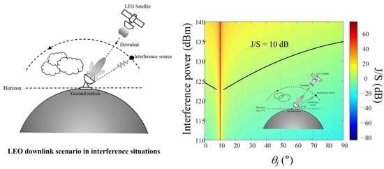
4. Analysis of LEO Satellite Downlink

To analyze the LEO downlink in interference situations, we set the scenario considering antenna patterns, the path loss in the space environment, and the interference source. The radiation patterns were obtained from the data transmitting antenna of the LEO satellite and the receiving ground station antenna in Section 2. We considered the bore-sight error loss by assuming that the transmitting and receiving antennas are slightly misaligned in the off-axis situation. The path loss calculated in Section 3 was then applied in the downlink analysis. In the given scenario, the LEO satellite transmits the data to the ground station, and the ground station antenna tracks the LEO satellite. The LEO satellite is located at the elevation angle of θgs. At the same time, it is assumed that the elevation angle θj of the interference source moves from 0° to 90° at an altitude of 10 km. The input power of the interference source can be adaptively controlled from 100 dBm to 150 dBm and is connected to a 10 dBi gain antenna. The interference power range was derived to maintain the target J/S such as 0 dB, 5 dB, 10 dB, and 15 dB when the interference source is located at various elevation angles. The detailed link budget parameters are listed in Table 1.
Figure 7 shows the J/S result according to the elevation angle θj and the interference power. “○” markers indicate the points at which the J/S is 0 dB. As can be seen, the result exhibits a large variance due to fluctuation in the antenna radiation pattern, which makes it difficult to observe the J/S tendency. To overcome this issue, we applied the regression model to “○” makers in our J/S result. This regression model (f1) is based on a quadratic function often used to fit raw data to a curved distribution [35,36]. The quadratic regression model can be expressed as (4)
f 1 ( θ j ) = a 1 θ j 2 + a 2 θ j + a 3
where a1, a2, and a3 are coefficients that best fit the points (“○” makers) with J/S = 0 dB, which is illustrated as the solid line. We then easily examined the tendency of the results by observing the single curved line.
Figure 8 illustrates J/S according to the elevation angle θj and the interference power at θgs = 10°. To obtain the J/S in the space environment, we applied the bore-sight error loss and atmospheric attenuation in Section 3 to the link budget calculation. In Figure 8a, the solid line indicates the regression model for the points with J/S = 0 dB in the space environment. To observe the effect of the space environment, we also examined the regression model (dashed line) without the space environment. To quantify the difference between the two cases, we defined β, which is the average difference between the two models expressed as (5):
β = 1 N k = 1 N P s ( k ) P f ( k )
where N is the number of elevation angle points, Ps is interference power of each elevation angle with the space environment, and Pf is interference power without the space environment. When the J/S = 0 dB, β is 3.53, which is due to the high atmospheric loss and bore-sight error at the low elevation angle of θgs = 10°. Figure 8b presents the regression model when J/S is changed to 5 dB, and it was observed that β is 2.56 dB in this case. Figure 8c,d illustrate the regression models with J/S = 10 dB and J/S = 15 dB, where β are 2.16 dB and 1.63 dB, respectively.
Figure 9 illustrates J/S with θgs = 60°, which is the result of seeing the effect of the space environment when the elevation angle θgs is increased. In Figure 9a, the solid and dashed lines indicate the regression models with and without the space environment when J/S is 0 dB. A reduced β of 0.02 was observed in this case because the atmospheric loss and bore-sight error decrease as the elevation angle θgs approaches 90°. Figure 9b, Figure 9c and Figure 9d present the regression models when J/S is changed to 5 dB, 10 dB, and 15 dB, respectively. For each case, β were 0.37 dB, 0.62 dB, and 0.14 dB, respectively. The detailed values of J/S results are listed in Table 2. As can be seen from the table, the smaller the elevation angle, the larger the overall β. The results demonstrate that it is necessary to consider the space environment to accurately analyze the LEO satellite downlink, especially at the low elevation angle of the satellite.

5. Conclusions

We analyzed the LEO satellite downlink, considering antenna patterns and the space environment in interference situations. The actual radiation patterns of the receiving and transmitting antennas were applied to more accurately estimate the data link budget when interference was strong in the side lobe of the receiving antenna. The choke ring horn type antenna with a diameter of 77.4 mm was used as the transmitting antenna in the LEO satellite, which had an HPBW of 103.2° and a maximum gain of 6.6 dBi at 8 GHz. The receiving antenna in the ground station was the parabolic type of antenna with a diameter of 11.3 m and an HPBW of 0.2°, with a maximum gain of 59 dBi at 8 GHz. We applied the space environment by employing the ray tracing technique and geometrical optics to calculate EM wave propagation. To observe the effects of the space environment, we examined the regression model with and without the space environment. To quantify the difference between the two cases, we defined β, which was the average difference between the two models. At θgs = 10°, β was from 1 dB to 4 dB, whereas β was from 0 dB to 1 dB at θgs = 60°. These results demonstrated that the bore-sight error and atmospheric attenuation increase due to the increased ray refraction, especially at low elevation angles, and thus it was important to consider the space environment for LEO satellite downlink analysis in interference situations.

Author Contributions

Conceptualization, H.C. and E.K.; methodology, E.K., J.K. and H.C.; soft- ware, E.K.; validation, E.K., J.K. and H.C.; formal analysis, E.K. and H.C.; investigation, E.K. and J.Y.; resources, E.K. and H.C.; data curation, E.K. and W.S.; writing—original draft preparation, E.K. and J.Y; writing—review and editing, Y.B.P., J.K., W.S., Y.P. and H.C.; visualization, E.K. and H.C.; supervision, H.C.; project administration, Y.P.; funding acquisition, H.C. All authors have read and agreed to the published version of the manuscript.

Funding

This research received no external funding.

Acknowledgments

This work was supported by Agency for Defense Development-Grant funded by Defense Acquisition Program Administration (UI210013YD).

Conflicts of Interest

The authors declare no conflict of interest.

References

  1. Lim, J.H.; Lee, J.W.; Lee, T.K.; Lee, H.C.; Lee, S.G.; Ryu, S.B.; Yoon, S.S. Performance evaluation of a modified Sweep SAR mode for quad-pol application in SAR systems. J. Electromagn. Eng. Sci. 2020, 20, 199–206. [Google Scholar] [CrossRef]
  2. Kang, Y.G.; Kim, C.K.; Park, S.O. Ocean image formation algorithm using altimeter data for next generation satellite SAR. J. Electromagn. Eng. Sci. 2022, 22, 85–94. [Google Scholar] [CrossRef]
  3. Jiang, W.; Zong, P. Analysis and validation of a new path loss model for LEO satellite communication systems. In Proceedings of the 2010 2nd International Conference on Computer Engineering and Technology, Chengdu, China, 16–18 April 2010; Volume 2, pp. V2-523–V2-527. [Google Scholar]
  4. Gongora-Torres, J.M.; Vargas-Rosales, C.; Aragon-Zavala, A.; Villalpando-Hernandez, R. link budget analysis for LEO satellites based on the statistics of the elevation angle. IEEE Access 2022, 10, 14518–14528. [Google Scholar] [CrossRef]
  5. Hofmann, C.A.; Knopp, A. Satellite downlink jamming propagation measurements at ku-band. In Proceedings of the MILCOM 2018-2018 IEEE Military Communications Conference, Los Angeles, CA, USA, 29–31 October 2018; pp. 853–858. [Google Scholar]
  6. Morong, T.; Puričer, P.; Kovář, P. Study of the GNSS jamming in real environment. Int. J. Electron. Telecommun. 2019, 65, 65–70. [Google Scholar]
  7. Lichtman, M.; Reed, J.H. Analysis of reactive jamming against satellite communications. Int. J. Satell. Commun. Netw. 2016, 34, 195–210. [Google Scholar] [CrossRef]
  8. Garcia, J.R.; Benammar, B.; Dudal, C.; Bompis, O.; Artaud, G.; Issler, J.L.; Guillon, H. Performance Comparison of Low Earth Orbit (LEO) Direct To Earth (DTE) High Data Rate Telemetry in X and Ka Bands; CNES: Toulouse, France, 2016.
  9. Tirkas, P.A.; Wangsvick, C.M.; Balanis, C.A. Propagation model for building blockage in satellite mobile communication systems. IEEE Trans. Antennas Propag. 1998, 46, 991–997. [Google Scholar] [CrossRef]
  10. Lee, H.C. Ku-band link budget analysis of UAV with atmospheric losses. In Proceedings of the 2006 IEEE/AIAA 25TH Digital Avionics Systems Conference, Portland, OR, USA, 15–18 October 2006; pp. 1–8. [Google Scholar]
  11. Merabtine, N.; Boualleg, A.; Benslama, M. Analysis of radiation patterns and feed illumination of the reflector antenna using the physical and geometrical optics. Semicond. Phys. Quant. 2006, 9, 53–57. [Google Scholar] [CrossRef] [Green Version]
  12. Florio, A.; Avitabile, G.; Coviello, G.A. Linear Technique for Artifacts Correction and Compensation in Phase Interferometric Angle of Arrival Estimation. Sensors 2022, 22, 1427. [Google Scholar] [CrossRef] [PubMed]
  13. Satsearch. Available online: https://satsearch.co/products/endurosat-x-band-4x4-patch-array-antenna (accessed on 1 October 2022).
  14. Mao, C.X.; Gao, S.; Wang, Y.; Chu, Q.X.; Yang, X.X. Dual-band circularly polarized shared-aperture array for C/X-band satellite communications, IEEE Antennas Wirel. Propag. Lett. 2017, 65, 5171–5178. [Google Scholar]
  15. García-Aguilar, A.; Inclán-Alonso, J.M.; Vigil-Herrero, L.; Fernández-González, J.M.; Sierra-Pérez, M. Low-profile dual circularly polarized antenna array for satellite communications in the X band. IEEE Trans. Antennas Propag. 2012, 60, 2276–2284. [Google Scholar] [CrossRef]
  16. Wettergren, J.; Dimming, P.; Johansson, J.F.; Öhgren, M. A high gain X-band isoflux helix antenna. In Proceedings of the 2016 10th European Conference on Antennas and Propagation, Switzerland, Davos, 10–15 April 2016. [Google Scholar]
  17. Lee, Y.J.; Lu, J.-H.; Tarn, I.-Y.; Chen, S.-L.; Chung, S.-J. An X-band circularly polarized antenna for satellite applications. In Proceedings of the 2014 Asia-Pacific Microwave Conference, Sendai, Japan, 4–7 November 2014. [Google Scholar]
  18. Dubrovka, F.; Martunyuk, S.; Dubrovka, R.; Lytvyn, M.; Lytvyn, S.; Ovsianyk, Y.; Piltyay, S.; Sushko, O.; Zakharchenko, O. Circularly polarised X-band H11- and H21-modes antenna feed for monopulse autotracking ground station. In Proceedings of the 2020 IEEE Ukrainian Microwave Week, Kharkiv, Ukraine, 21–25 September 2020. [Google Scholar]
  19. Cheong, S.S.; Kim, T.-H.; Jung, J.-M.; Lee, S.-G.; Kim, Y.-H. Design of 2-axis gimbal spaceborne x-band antenna for high data rate payload transmission. In Proceedings of the 2013 Asia-Pacific Microwave Conference, Seoul, Korea, 5–8 November 2013. [Google Scholar]
  20. Tomoki, K.; Saito, H. Dual circularly polarization antenna with high XPD for downlink communication of earth observation satellite. In Proceedings of the 2017 IEEE Conference on Antenna Measurements & Applications, Tsukuba, Japan, 4–6 December 2017. [Google Scholar]
  21. Chahat, N.; Amaro, L.R.; Harrell, J.; Wang, C.; Estabrook, P.; Butman, S.A. X-band choke ring horn telecom antenna for interference mitigation on NASA’s SWOT mission. IEEE Trans. Antennas Propag. 2016, 64, 2075–2082. [Google Scholar] [CrossRef]
  22. Arnaud, E.; Dugenet, J.; Elis, K.; Girardot, A.; Guihard, D.; Menudier, C.; Monediere, T.; Roziere, F.; Thevenot, M. Compact isoflux X-band payload telemetry antenna with simultaneous dual circular polarization for LEO satellite applications. IEEE Antennas Wirel. Propag. Lett. 2020, 19, 1679–1683. [Google Scholar] [CrossRef]
  23. Akan, V. Choke ring horn antenna design for satellite payload data transmitters. Microw. Opt. Technol. Lett. 2021, 63, 1913–1919. [Google Scholar] [CrossRef]
  24. Fouany, J.; Thevenot, M.; Arnaud, E.; Torres, F.; Monediere, T.; Adnet, N.; Manrique, R.; Duchesne, L.; Baracco, J.M.; Elis, K. Circurlaly polarized isoflux compact X band antenna for nano-satellites applications. In Proceedings of the 2015 European Radar Conference, Paris, France, 9–11 September 2015; pp. 381–384. [Google Scholar]
  25. El-Hassan, M.A.; Hussein, K.F.A.; Farahat, A.E.; Awadalla, K.H. X-Band isoflux concentric circular antenna arrays for image data download from LEO satellites to ground stations. Appl. Comput. Electromagn. Soc. J. 2019, 34, 1694–1703. [Google Scholar]
  26. Nawaz, W.; Ali, A.S. Improvement of gain in dual fed X band isoflux choke horn antenna for use in LEO satellite mission. In Proceedings of the 2015 Fourth International Conference on Aerospace Science and Engineering, Lahore, Pakistan, 2–4 August 2015; pp. 1–4. [Google Scholar]
  27. ITU. Radiation Diagrams for Use as Design Objectives for Antennas of Earth Stations Operating with Geostationary Satellites; Recommendation ITU-R, S. 580-6; ITU: Geneva, Switzerland, 2003. [Google Scholar]
  28. Kim, C.; Park, Y.B. Prediction of electromagnetic wave propagation in space environments based on geometrical optics. J. Electromagn. Eng. Sci. 2017, 17, 165–167. [Google Scholar] [CrossRef]
  29. Balanis, C.A. Advanced Engineering Electromagnetics, 2nd ed.; Wiley: Chichester, UK, 2012; pp. 742–761. [Google Scholar]
  30. Bean, B.R. The radio refractive index of air. Proc. IRE 1962, 50, 260–273. [Google Scholar] [CrossRef]
  31. Liebe, H.J. MPM-An atmospheric millimeter-wave propagation model. Int. J. Infrared Millimeter Waves 1989, 10, 631–650. [Google Scholar] [CrossRef]
  32. Atmospheric Soundings–Wyoming Weather Web. Available online: http://weather.uwyo.edu/upperair/sounding.html (accessed on 1 October 2022).
  33. Papas, C.H. Theory of Electromagnetic Wave Propagation; Perlego: New York, NY, USA, 2014; pp. 165–201. [Google Scholar]
  34. ITU. Ionospheric Propagation Data and Prediction Methods Required for the Design of Satellite Networks and Systems; Recommendation ITU-R, P.531-14; ITU: Geneva, Switzerland, 2019. [Google Scholar]
  35. Jang, D.; Youn, S.; Lee, J.Y.; Choo, H. Statistical indoor exclusion zone analysis by investigating electromagnetic fields inside a nuclear power plant. Appl. Sci. 2021, 11, 4199. [Google Scholar] [CrossRef]
  36. Fumo, N.; Biswas, M.R. Regression analysis for prediction of residential energy consumption. Renew. Sust. Energ. 2015, 47, 332–343. [Google Scholar] [CrossRef]
Figure 1. Conceptual figure of the LEO downlink scenario in interference situations.
Remotesensing 15 01748 g001
Figure 2. Transmitting antenna of the satellite and the far-zone radiation pattern: (a) transmitting antenna of the LEO satellite; (b) radiation pattern and requirement masks.
Remotesensing 15 01748 g002aRemotesensing 15 01748 g002b
Figure 3. Receiving antenna of the ground station and the far-zone radiation pattern: (a) receiving antenna of the ground station; (b) far-zone radiation pattern of the ground station.
Remotesensing 15 01748 g003aRemotesensing 15 01748 g003b
Figure 4. Geometrical optics model in a space environment.
Remotesensing 15 01748 g004
Figure 5. Bore-sight error and atmospheric attenuation when transmitting signals from the LEO satellite to the Earth ground station: (a) bore-sight error; (b) atmospheric attenuation.
Remotesensing 15 01748 g005
Figure 6. Normalized received power at θgs = 10°: (a) in free space; (b) in the space environment.
Remotesensing 15 01748 g006
Figure 7. J/S according to the elevation angle θj and the interference power. “○” is when J/S = 0 dB, and the solid line is the regression model.
Remotesensing 15 01748 g007
Figure 8. J/S according to the elevation angle θj and the interference power at θgs = 10°: (a) J/S = 0 dB; (b) J/S = 5 dB; (c) J/S = 10 dB; (d) J/S = 15 dB.
Remotesensing 15 01748 g008
Figure 9. J/S according to the elevation angle θj and the interference power at θgs = 60°: (a) J/S = 0 dB; (b) J/S = 5 dB; (c) J/S = 10 dB; (d) J/S = 15 dB.
Remotesensing 15 01748 g009
Table 1. Downlink parameters for the link budget in the scenario.
Downlink ParametersValues
Receiving antenna gain59 dBi
Satellite altitude550~2200 km
Frequency range8025~8400 MHz
Transmitting power30 dBm
Transmitting antenna bore-sight gain (dBi)4.4 dBi
Effective isotopic radiation power (EIRP), Gt + Pt34.4 dBm
Free-space path lossLf dB
Bore-sight error lossLb dB
Atmospheric attenuationLat dB
Interference source power100~150 dBm
Interference source antenna gain10 dBi
Interference source altitude10 km
Table 2. J/S results depending on the J/S and θgs.
θgs1060
J/S (dB)051015051015
β (dB)3.532.562.161.630.020.370.620.14
Disclaimer/Publisher’s Note: The statements, opinions and data contained in all publications are solely those of the individual author(s) and contributor(s) and not of MDPI and/or the editor(s). MDPI and/or the editor(s) disclaim responsibility for any injury to people or property resulting from any ideas, methods, instructions or products referred to in the content.

