Article

Ground-Based Oblique-View Photogrammetry and Sentinel-1 Spaceborne RADAR Reflectivity Snow Melt Processes Assessment on an Arctic Glacier

by
Jean-Michel Friedt
1,*,
Éric Bernard
2 and
Madeleine Griselin
2
1
FEMTO-ST, Time & Frequency, 15 Avenue de Montboucon, 25000 Besançon, France
2
TheMA, 26 rue Megevand, 25000 Besançon, France
*
Author to whom correspondence should be addressed.
Remote Sens. 2023, 15(7), 1858; https://doi.org/10.3390/rs15071858
Submission received: 24 February 2023 / Revised: 24 March 2023 / Accepted: 28 March 2023 / Published: 30 March 2023
(This article belongs to the Special Issue Remote Sensing in Snow and Glacier Hydrology)

Abstract

:
The snowpack evolution during the melt season on an Arctic glacier is assessed using ground-based oblique-view cameras, spaceborne imaging and spaceborne RADAR. The repeated and systematic Synthetic Aperture RADAR (SAR) imaging by the European Space Agency’s Sentinel-1 spaceborne RADARs allows for all-weather, all-illumination condition monitoring of the snow-covered fraction of the glacier and hence assessing its water production potential. A comparison of the RADAR reflectivity with optical and multispectral imaging highlights the difference between the observed quantities—water content in the former, albedo in the latter—and the complementarity for understanding the snow melt processes. This work highlights the temporal inertia between the visible spring melting of the snowpack and the snow metamorphism. It was found that the snowpack exhibits that approximately 30 days before it starts to fade.

1. Introduction

The snowpack is a highly significant proxy to understand the response of the cryosphere to climate variations [1,2,3,4]. It is actively involved in glaciers’ dynamics: its behavior drives the capacity of the glacier to accumulate or melt during positive or negative mass balances, respectively. In addition, because the snowpack lasts 8–10 months a year in Svalbard [5,6], we can state, as demonstrated by [7,8,9], that it is the main driver of the glacier hydrological response. It controls melting processes as well as surface outflows [10,11,12].
An observation site has been the focus of glaciological and hydrological investigations on the Austre Lovén glacier in Svalbard (High Arctic), to quantify and analyze the processes occurring in such a small hydrosystem. Among these processes, the melting dynamics of the glacier itself and its effects on the global hydrological system have been the subject of several observations and studies [13,14,15]. In each case, it was found that the increase in precipitation leads to increased rainfall at low altitude and more snow fall above the rain–snow boundary altitude, and therefore to increased run-offs and melt water fluxes [16,17,18,19]. Indeed, in the context of global warming, the rain–snow boundary altitude rises, but nevertheless, above this limit, increased snow fall is observed [20,21].
In Svalbard (Figure 1), the snowpack is drastically driven by the climatic parameters strongly affected by the ocean [22]. Due to recent observed changes, including the precipitation, ref. [5] has suggested that the snowpack now has to be considered in a context of a High Arctic maritime snow climate. This means that it is strongly affected by the alternating solid/liquid precipitation. Several ice layers in the snowpack are among factors to be considered as water supply, which could be fully released during a melting phase [23]. This differentiates this study from similar past investigations in the Alps [24,25,26].
From the practical point of view, many processes occur in the snowpack long before it is visible at the surface. Hence, the identification of the impact of a changing snowpack on glacier dynamics was included among the objectives of the observatory site. This point was undertaken by studying more specifically the spatial dynamics of the snowpack during the melting season, mainly through the fractional snow cover (FSC) determination.
In order to meet this requirement, a network of automated cameras was initially installed around the glacier basin a decade ago [27]. The collected data provide an accurate estimation of the FSC after post-processing oblique-view pictures projected as azimuthal maps. Nevertheless, these data only yield the snow/ice discretization: on the one hand, optical imagery is prone to dataloss, either due to poor weather conditions even for ground-based cameras (snow or rain fall and moisture condensation on lenses) or instrument failure (Figure A1). Similarly, spaceborne optical and multispectral imagery as provided, for example, by Sentinel-2 satellites appears challenging over high-latitude areas due to the dense cloud cover during the melt season, with only very few spaceborne pictures usable for an analysis of the snowpack cover over the glacier.
Spaceborne RADAR is an active remote sensing technique benefiting from the motion of the satellite along its orbit for imaging by applying Synthetic Aperture RADAR (SAR) processing: the Sentinel-1 satellites illuminate the surface of the Earth in the C-band, resulting in a 5 × 20 m ground resolution in the interferometric wide (IW) mode. In addition, to operate under all weather and illumination conditions, microwave spaceborne RADAR provide a rich set of information on the internal processes of the snowpack beyond the binary absence or presence. Indeed, the 5.5 cm wavelength C-band RADAR signal we shall consider here will quickly vanish in a wet snowpack even under shallow cover over the dry ice acting as a strong reflector.
In this paper, we highlight the combined use of freely accessible spaceborne C-band RADAR data and in situ optical digital pictures for the observation and the quantification of snowpack melting processes on a glacier surface, in line with past work, emphasizing the complementarity of optical and active microwave measurements [28,29,30]. We start by introducing the automated digital camera network we deployed a decade ago for the systematic imaging of the glacier basin. We then introduce the two spaceborne datasets analyzed, namely Sentinel-1 RADAR [31,32,33] and Sentinel-2 Infrared images [34]. The projected oblique-view images, RADAR reflectivity maps and aerial images are compared for consistencies and inconsistencies. The discussion emphasizes the benefits of the all-weather, all-illumination acquisition capability of RADAR over optical collection means, and the complementarity of the microwave interaction with the binary optical observation of the snowpack distribution. The qualitative binary classification of the microwave reflectivity leads to a quantitative FSC over the glacier, complementing the optical and multispectral reflectivity classification with the identification of the water content in the snow only accessible to RADAR measurements.

2. Materials and Methods

2.1. Ground-Based Oblique-View Photograph Processing

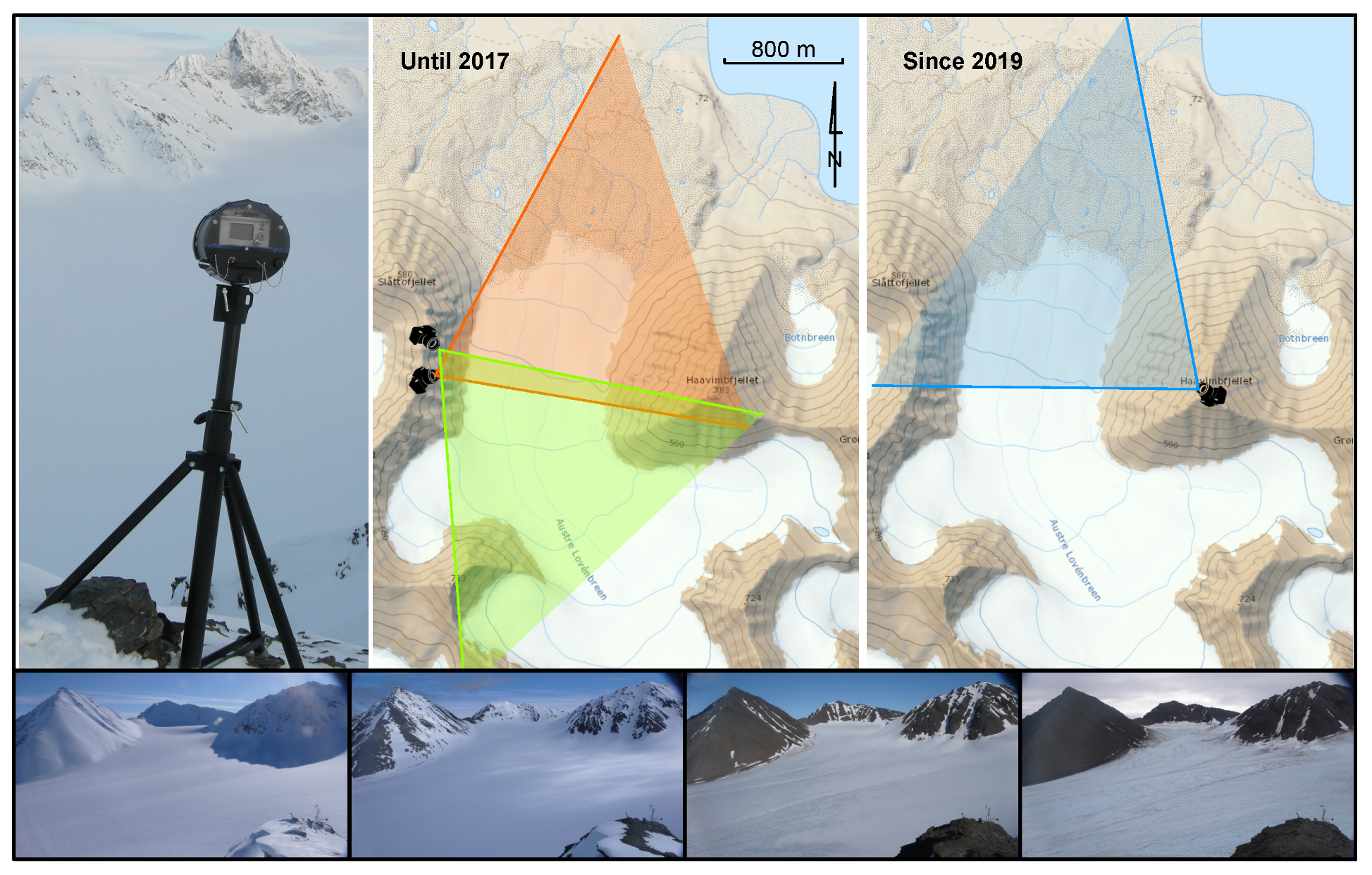
Since 2008, a network of 6 automated photo stations has been deployed around the Austre Lovén glacier in order to follow different processes with a focus on glaciological dynamics (Figure 2). All stations have been set to take 3 photos per day at 8 a.m., 12 a.m. and 4 p.m. in order to maximize chances of acquiring at least one usable image every day. This network runs all year long thanks to combined solar panel and lithium battery power supply. This network, described in [27], was set up this way mainly in order to minimize the influence of poor weather conditions and to provide cross-coverage of most of the glacier surface. A camera was setup in Spring 2019 on one of the highest peaks (Haavimbfjellet, 780 m.a.s.l.) surrounding the glacier basin. Similar to the rest of the network, during the whole year, the camera collected 3 photos/day which can be accurately timestamped as long as the real time clock keeps on being powered. Because only the forefield and the glacier snout were included in each viewshed, the melting is only observed during approximately a single week, beginning in July 2019. Nevertheless, some insight can be gained from this Haavimb camera dataset:
  • Reaching higher ground leads to greater chances of the camera being shielded by clouds from taking pictures of the glacier (Appendix A).
  • The area observed by a single camera is limited to the glacier snout and will hence only provide reference observations for the early melt season.
  • Ground-based imaging remains more favorable than spaceborne imaging because under most circumstances the cameras are below clouds even when the satellite is prevented from observing the glacier basin, but oblique-view imaging requires azimuthal projection post-processing and some areas of the glaciers are hidden below the curvature of the ice surface.
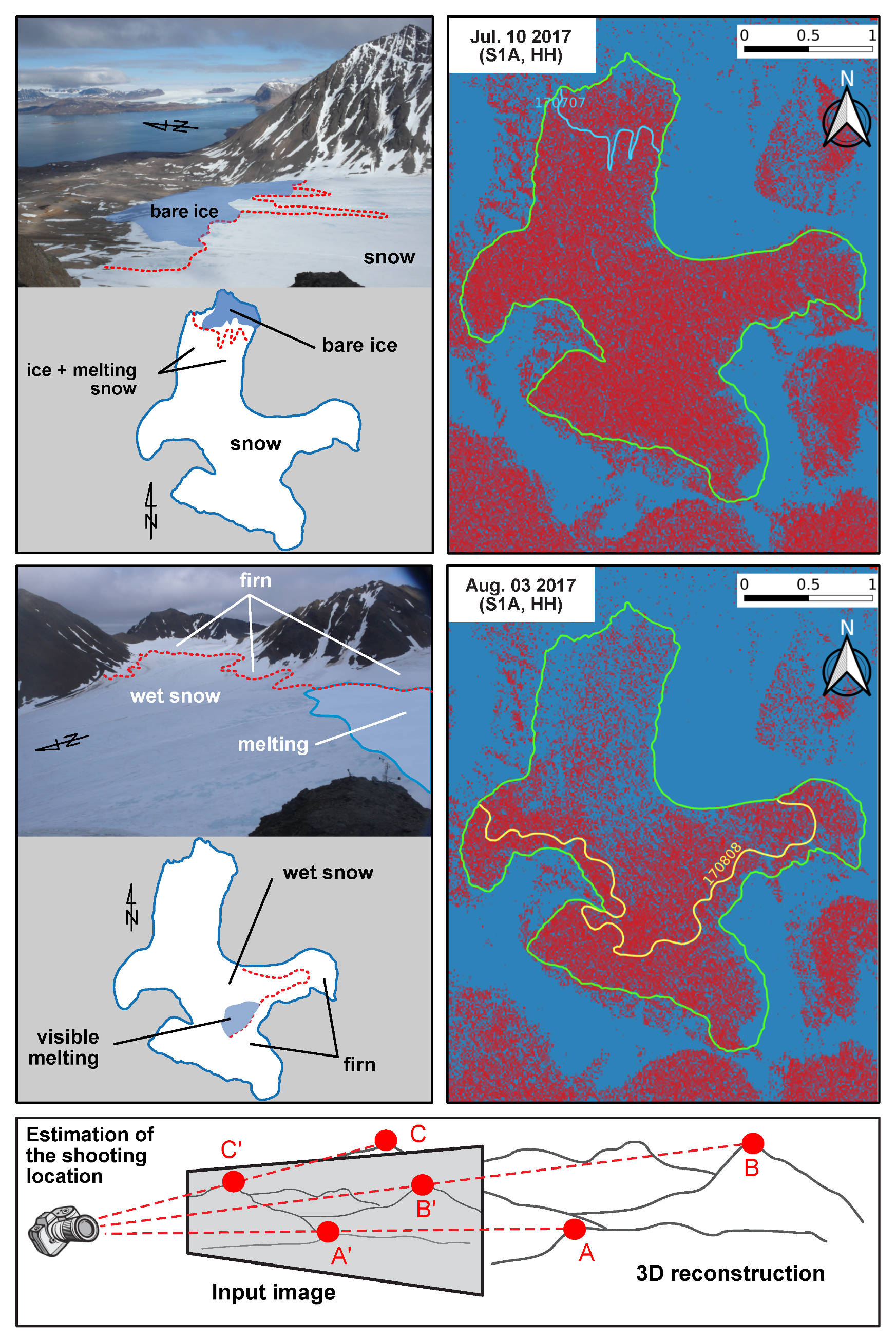
For this work, we aim to determine a change in the snow-covered/snow-free state on the ground surface and more specifically on the glacier surface quality (snow or ice). Here, we focus on the FSC which is derived from an image analysis, manually cropping the limit between the snowpack and the area free of snow. To undertake this analysis, the data were processed with the WSL MPT (Monoplotting Tool, available at https://www.wsl.ch/de/metanavigation/services-und-produkte/software-websites-und-apps/monoplotting-tool.html accessed on 20 March 2023). As described by [35], the Monoplotting Tool (MPT) allows georeferencing landscape oblique terrestrial or aerial photographs, to be used for quantitative measurements and analysis. Thanks to a mathematical model, it is possible to combine the georeferenced image with the Digital Elevation Model (DEM), to connect each point (pixel) of the image with the corresponding world coordinates (Figure 3 summarizes the process). Thus, a georeferenced photograph becomes a geographical map projected on a DEM compatible with zenithal projection over other georeferenced datasets. Hence, for each observed change in snowpack distribution, we used and processed the closed usable photo selected as being free of cloud cover or moisture condensation on the lense. Thanks to the zenithal projection of the resulting images, multiple camera pictures can be assembled as a single mosaic covering the glacier basin, allowing tracking of the snow-covered/snow-free boundary over the whole melt season, spanning typically from beginning of July to end of August, and computing the resulting FSC.

2.2. Spaceborne RADAR Signal Collection and Processing

Sentinel-1 is a set of two satellites—A and B—orbiting the Earth at an altitude of 700 km carrying C-band (5405 MHz center frequency, 100 MHz bandwidth) spaceborne RADAR. Launched in 2014 and 2016, archives of all collected data are freely available on the European Space Agency website, Copernicus Hub. Unlike other spaceborne RADAR missions (e.g., Canadian RADARSAT, German Terra SAR or Japanese ALOS) focusing on some specific scientific or strategic target mapping upon request, each Sentinel-1 consistently and repeatedly maps the surface of the Earth once every 12 days and all data are stored for further processing of any long-term monitoring endeavor as considered here. With a repeated flight period of 12 days over the same orbital track for interferometric analysis, the high-latitude location of Spitsbergen is best suited for repeated measurements. Practically, 1 satellite is observed to map the Brøgger peninsula in the 20 × 5 m2/pixel high-resolution interferometric wide (IW) mode once every 6 days. The Single Look Complex (SLC) data are downloaded from the Copernicus Hub website at https://scihub.copernicus.eu/dhus (accessed on 20 March 2023) and processed using the SNAP library and its command line tool gpt. The processing sequence is as follows:
  • Split for selecting one or two bursts covering the Brøgger peninsula in a single subswath, both parameters having been identified for each possible orbital track with the SNAP graphical user interface;
  • Seamless integration of successive RADAR bursts in case more than a single burst was selected (deburst function);
  • Range-Doppler Terrain correction for projecting the dataset on an external Digital Elevation Model (DEM), in our case the 5 m DEM provided by Norwegian Polar Institute at https://data.npolar.no/dataset/dce53a47-c726-4845-85c3-a65b46fe2fea (accessed on 20 March 2023) and producing a UTM 33N projected map readily inserted in QGIS. From this analysis, we focus on the HH polarization because the HV is observed to hardly provide any information on the snow cover of the glacier.
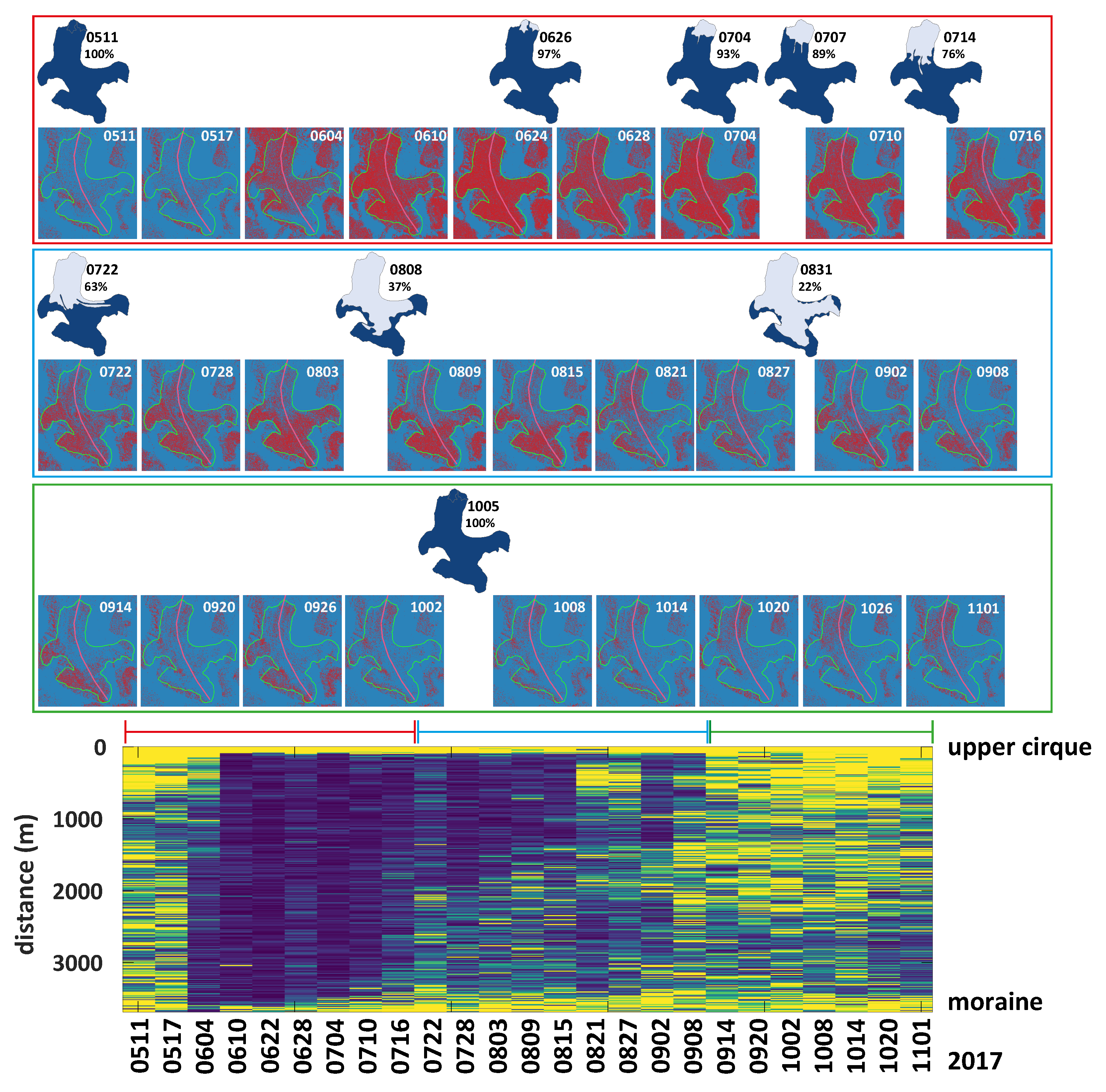
Throughout this analysis, we exclusively focus on similar emitted and reflected polarization (HH or VV) reflectivity because we observe little information on cross-polarization datasets. In addition to the scalar reflectivity along the main line of the glacier, as shown in Figure 4, FSC identification benefits from the mapping capability of SAR. Figure 4 depicts Sentinel-1 images collected from 11 May 2017 (top-left picture) to 1 November 2017 (bottom-right) with datasets separated by 6 days unless unavailable from the ESA Copernicus website. A comparison of the projected oblique-view images is given along the chart when striking evolutions of the snowpack were observed. In the center of Figure 4, the reflectivity evolution along the centerline is displayed, with the highest altitude (south) on top and and lowest latitude (moraine north) on the bottom.
While optical measurements are subject to weather conditions (cloud cover) and illumination, preventing observations during the polar night, spaceborne RADAR dataset allows for extending the snow cover fraction measurement beyond the optical observation schedule once the matching scenes have been verified on the common datasets.
All RADAR reflectivity maps are displayed as binary reflectivity information with a threshold value of 3000 arbitrary units, with red displaying strongly absorbing areas (reflected intensity below 3000) and blue displaying strongly reflective areas (reflected intensity above 3000). The threshold value of 3000 was selected as the value rounded to the closest thousand of the median value (along the time series) of the median values along each transect of the reflected intensity, i.e., expressed as
m e d i a n ( m e d i a n ( reflected   signal ) )
on the dataset shown in Figure 4 (bottom).

2.3. Spaceborne Multispectral Image Collection

Because oblique-view image projection is challenging under poor lighting conditions, optical and near-infrared (NIR) multispectral images acquired by Sentinel-2 are collected from the Sentinel Hub EO Browser (https://apps.sentinel-hub.com/eo-browser/ accessed on 20 March 2023) as provided by L1C datasets. Most significantly, the Normalized Difference Water Index (NDWI) estimator resulting from ( B 3 B 8 ) / ( B 3 + B 8 ) with B 3 the green band centered on 560 nm and B 8 the near-infrared band centered on 842 nm. This index was selected over the Normalized Difference Snow Index (NDSI) because we aim at differentiating snow, water-soaked snow and ice rather than snow and ice from rock as exhibited by the latter, and it is complemented with short wave infrared composite (SWIR) [34].
These two bands are collected as georeferenced TIF files from the EO browser and inserted in QGIS for comparison with the projected oblique-view images and the RADAR datasets, emphasizing the challenge of collecting spaceborne optical images of Spitsbergen during the summer melt season due to the heavy cloud cover. During the whole 2017 melt season ranging from 3 July to 12 August, only 9 usable satellite pictures were downloaded.

3. Results and Analysis

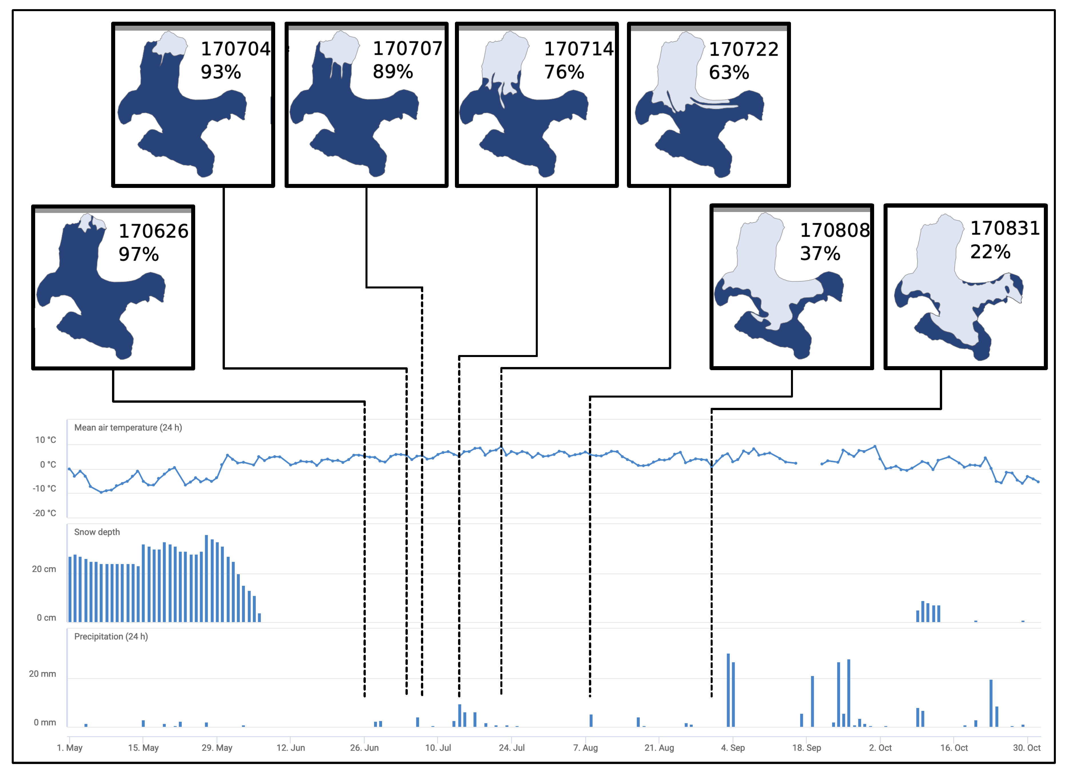
Our initial investigation on the ground-based oblique-view images led to charts as depicted in Figure 5, with the comparison of the evolution of the FSC (top) with weather proxies such as the temperature (middle-top), the snow depth in the nearby Ny-Ålesund observations at sea level (middle-moddle) and precipitations (middle-bottom). We notice by comparing the Ny-Ålesund weather station snow depth measurement and the glacier FSC maps that thanks to the elevated location and the thermal inertia brought by the underlying glacier, snow remains present one month longer on the glacier during the melt season with respect to the moraine. In this investigation, we wish to improve the time resolution between the ground-based collected data by comparing it with the spaceborne all-weather RADAR data, assessing the consistency of the resulting FSC and assessing the quality of the manually defined boundaries between the snow and ice covered areas as identified by the optical colorimetric analysis, as opposed to multispectral reflectivity when using spaceborne images from Sentinel-2.
Ground-based cameras are less prone to poor weather and missing pictures due to excessive cloud cover or rain than spaceborne optical imaging. Yet some data are lost to poor weather conditions as illustrated in Figure A1 of the Appendix A, highlighting some of the data collected in 2017. Nevertheless, assessing the azimuthal projection through monoplotting and possibly complementing ground-based acquisitions with spaceborne images requires a detailed comparison with Sentinel-2 images, despite the very few usable available datasets due to the dense cloud cover over Spitsbergen during the spring and summer. Under most circumstances, the ground-based oblique-view images and spaceborne multispectral images collected by Sentinel-2 display consistent snow cover, as shown in Figure 6.
Nevertheless, the benefit of the active microwave RADAR illumination over a passive optical observation becomes obvious when considering the ratio of usable datasets at both wavelengths. Indeed, knowing that Sentinel-2 provides an image per day and considering the melting period (i.e., from early June to the end of August), we should process 90 images. Yet between 2017 and 2019, only an average of 18 Sentinel-2 images per melt season, ranging from 1 June to 30 September every year, are usable. For most of the other images, the cloud coverage makes analysis impossible.
As an example of the information resulting from spaceborne RADAR maps, Figure 4 provides an estimate of the HH reflected intensity, in arbitrary units, as a function of time during the melt season (x-axis) and the altitude along a central transect (y-axis with the lowest altitude in the moraine at the bottom of the chart and the highest in the cirque on the top). The glacier area is mostly reflecting incoming microwaves (two pictures on the left, bright areas over the whole glacier) until the temperature reaches a positive threshold when the snow starts melting. From the third RADAR map dated 4 June 2017, the glacier is observed as a dark surface which is interpreted as microwaves being absorbed by the wet snowpack rather than being reflected by the ice after penetrating the dry snowpack, as was the case with the negative temperature. As the melt season goes on, a bright area is seen to spread from the lowest area at the north (top) of each picture toward the highest areas at the south (bottom), matching the pattern of the snowpack melt. Once the whole snowpack has melted, the glacier again appears as a bright surface, with the bare ice reflecting the microwaves rather than absorbing them. The evolution of the reflectivity along the central transect is illustrated in the chart at the center of Figure 4, where the initial bright-to-dark transition is observed in the second column, with the melt evolving from the lowest to highest altitude observed as the rising yellow to blue interface on the chart, until the whole snowpack has melted and the glacier appears again as a bright reflector to the spaceborne RADAR.
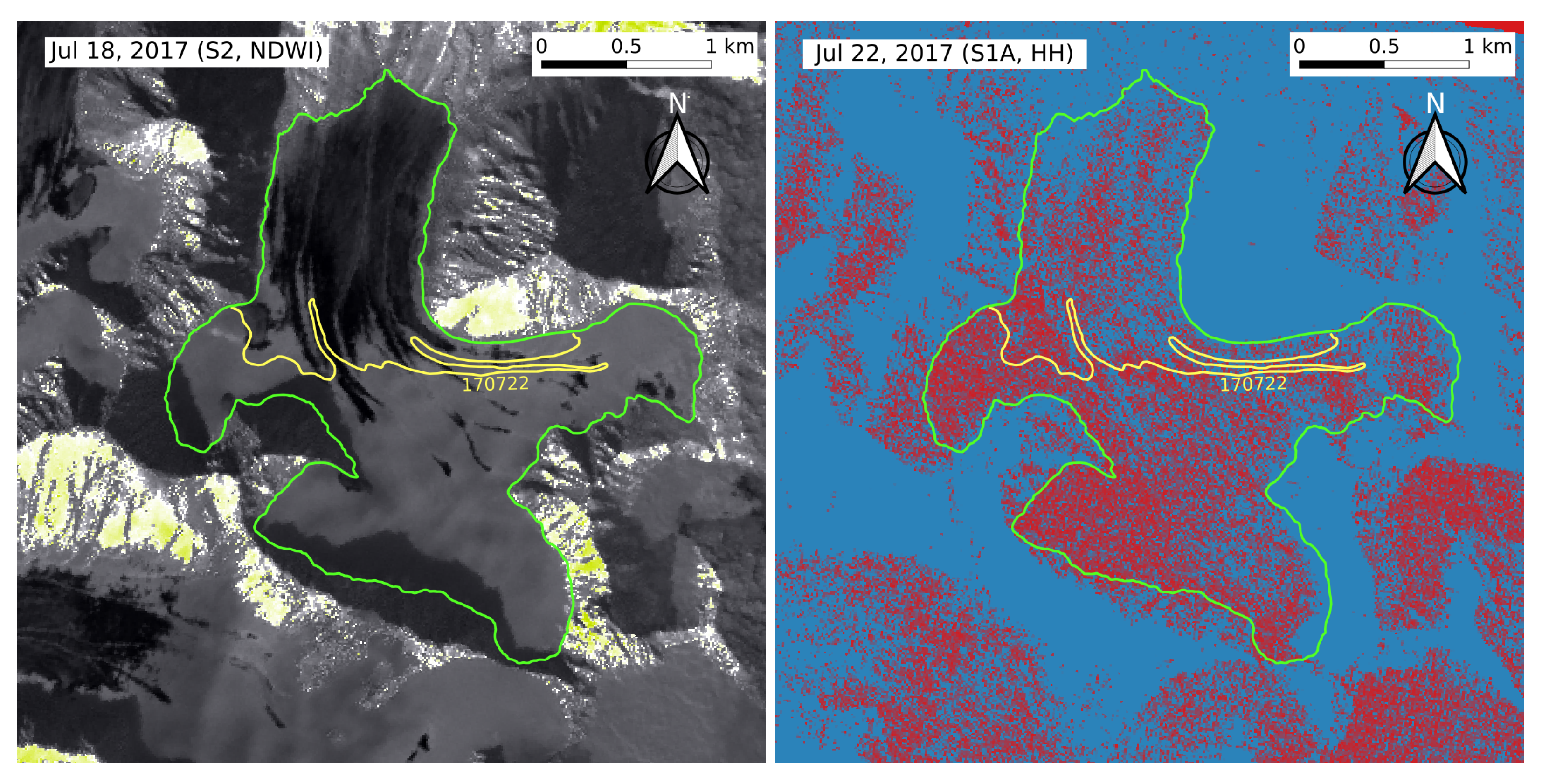
While investigating the snow cover detected by the RADAR dark (wet snow) and bright (dry ice) areas and comparing with the ground-based oblique-view orthorectified maps, inconsistencies led us to compare spaceborne multispectral imagery with spaceborne microwave RADAR (Figure 7). Despite the few cloud-free days, Sentinel-2 collected images over Spitsbergen, and some spaceborne images are synchronous with the ground-based image analysis: we interpret the discrepancy by the better contrast provided by the spaceborne multispectral imagery and the challenge of differentiating, under cloud-covered conditions, the snow- or ice-covered areas, both appearing as bright white on optical ground-based pictures.
All the dataset comparisons highlight an FSC limit at a higher altitude when analyzing the optical images than by processing the RADAR datasets. We interpret this discrepancy by the different quantities measured at the optical and microwave wavelengths:
  • Initially, at the end of the winter, the bright snow appears as a strongly reflective homogeneous layer at optical wavelengths and the dry snow allows for the microwave penetration to the ice surface and its reflection back to the RADAR receiver, displaying a strong microwave reflectivity.
  • As the temperature rises above the snow melting point, the snowpack fills with liquid water but remains optically bright with a strong albedo. The microwave is however attenuated by the water and is no longer reflected by the snow–ice interface: while the glacier remains with a high albedo at optical wavelengths, it suddenly becomes dark at microwave wavelengths with the whole snowpack saturated with water. Only the upper part of the glacier remains bright for a short duration as the heat wave rises, inducing the snow melt and high water content of the snowpack.
  • As the melt season starts, the snowpack both melts and is carried away by flowing water. While optical imaging shows the snowpack recess with exposed dark ice observed as low multispectral reflectivity regions, the microwave remains absorbed by a water-soaked snowpack and water running over the ice close to the FSC. Hence, the low microwave reflectivity region extends over areas that are identified optically as below the ice–snow limit, either due to the water-soaked snowpack appearing dark optically or running water on the surface of the ice as the snow melts and only dry ice well below the ice–snow limit appears as a bright microwave reflecting surface.
  • Once the whole snowpack has melted at the end of the melt season, the glacier appears again as a bright microwave reflector as its surface has dried and no longer absorbs the microwaves, while optical and infrared imaging observe the bare ice surface as a lower albedo surface than the initial snow-covered surface.
A detailed analysis of Figure 8 is as follows:
  • On the left column, from top to bottom: On 17 May (VV polarization) or 13 May (HH polarization), the RADAR map hints at a dry snow cover reflecting the microwave signal, with blue meaning strong reflectivity, whereas the spaceborne and ground-based pictures indicate a fully white homogeneous snow cover. All the 2017 Sentinel-1 acquisitions are collected in horizontal (H) polarization while the 2019 acquisitions provide both horizontal and vertical (V) polarized illumination. Nevertheless, little difference is observed between H and V as long as the copolarization reflectivity maps are analyzed.
  • On the middle column, from top to bottom: On 10 June (VV polarization) or 6 June (HH polarization), the RADAR imaging observes a wet glacier snout, with red meaning low reflectivity, because the microwave is absorbed by the wet snow, while the upper part of the glacier remains dry, but the optical spaceborne and ground-based camera images remain homogeneously white. The only hint of melt in the ground-based camera is the avalanche highlighted by the yellow arrows (bottom).
  • On the right column, from top to bottom: On 16 June (VV polarization) or 18 June (HH polarization), the whole snowpack is saturated with water following the warm period (positive temperatures), with a strong microwave attenuation over the whole glacier appearing as red, and yet the optical images collected by Sentinel-2 still remain fully white. Clues of snowpack humidification on the Sentinel-2 image are hinted, with the snow swamps and supraglacial lake formation highlighted as red rectangles and the supraglacial lake (bottom right) and outflows (three upper rectangles) magnified. The ground-based optical image still displays a fully white snow cover except for the wet, loose snow avalanche (yellow arrows on the bottom ground-based picture).
This analysis, summarized in Figure 9, highlights the complementarity of the three measurement techniques, the microwaves being most significantly impacted by the liquid water presence in the snowpack or the ice surface, while the optical (ground-based) and multispectral (spaceborne) imaging will be mostly impacted by albedo, with the challenge of varying natural light illumination conditions attenuating, under some conditions, the difference between the intensity reflected by the snow or ice. This effect, most visible on the ground-based optical images, is partly solved with the near-infrared band which is most strongly impacted by the snow or ice reflectivity. Field trips (Figure 9, bottom) provide an in situ validation of the interpretation of the remote sensing data.
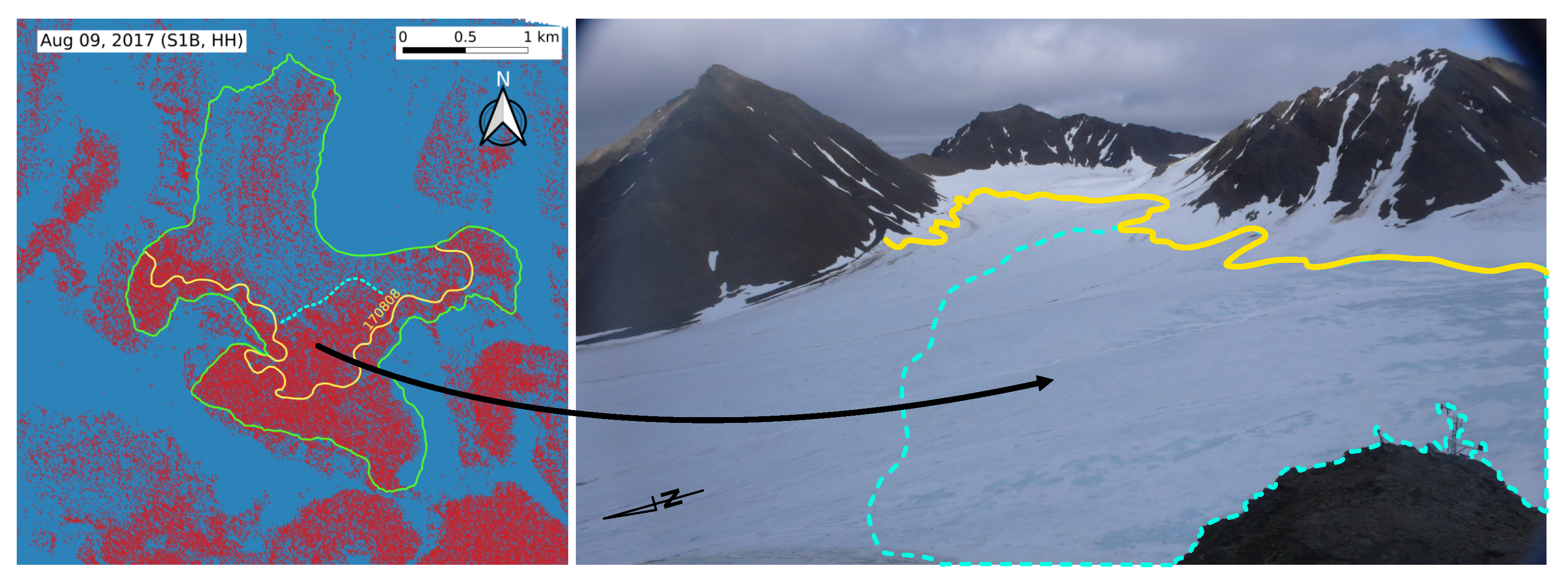
This analysis is applied to a dataset collected at the end of Summer 2017, when the discrepancy between the optical image analysis and RADAR microwave reflectivity is most pronounced (Figure 10). While the initial FSC was delineated at the boundary between dark, bare ice patches partly covered with snow (Figure 10, right), the microwave reflectivity measurements hint at wet, but strongly absorbing, regions well below the FSC, with areas still actively feeding the hydrological budget with abundant run-off.

4. Conclusions

The FSC (fraction snow cover) can be determined based on the optical data analysis, to deduce the surface of the glacier and its corresponding melting coefficient. However, many dynamics remain unseen, specifically during the key melting season. The investigation of the electromagnetic reflectivity of the snowpack during its melt process over an Arctic glacier as monitored by C-band spaceborne RADARs highlights the complementarity with optical images, whether collected from ground-based camera or multispectral spaceborne images. Both the repeatability and physical properties of the Sentinel-1 RADAR acquisitions enable an accurate spatio-temporal identification of the snowpack water content despite the lower spatial resolution with respect to ground-based cameras. In addition to its all-weather/all-illumination condition capability, RADAR imaging provides information relevant to hydrological processes. This approach not only overcomes the weather conditions but also gives way more information about the control of snowpack dynamics over periglacial hydrology.

Author Contributions

J.-M.F. contributed to conceptualization, methodology, software and format analysis as well as writing, reviewing and editing. É.B. contributed conceptualization, methodology, and formal analysis as well as writing, reviewing and editing. M.G. contributed supervision and funding acqusition. All authors have read and agreed to the published version of the manuscript.

Funding

This work was supported by a Région Franche-Comté grant and by Institut Paul-Émile Victor (IPEV).

Conflicts of Interest

The authors declare no conflict of interest.

Appendix A

Figure A1 illustrates some of the poor weather conditions preventing the use of optical observation methods even when located on the ground, while spaceborne RADAR observations are not affected by poor weather or weak illumination conditions.
Figure A1. (Top): poor weather conditions preventing optical ground-based cameras from collecting pictures, excluding failure to trigger due to exhausted batteries, jammed motor for motorized lenses and microcontroller reset due to electrostatic discharge generated by blown dry snow. (Bottom): associated spaceborne RADAR reflectivity maps exhibiting FSC limits as boundaries between bright reflective regions and dark absorbing regions.
Remotesensing 15 01858 g0a1

References

  1. Bavay, M.; Grünewald, T.; Lehning, M. Response of snow cover and runoff to climate change in high Alpine catchments of Eastern Switzerland. Adv. Water Resour. 2013, 55, 4–16. [Google Scholar] [CrossRef]
  2. Hock, R. A distributed temperature-index ice-and snowmelt model including potential direct solar radiation. J. Glaciol. 1999, 45, 101–111. [Google Scholar] [CrossRef]
  3. Sobota, I.; Weckwerth, P.; Grajewski, T. Rain-On-Snow (ROS) events and their relations to snowpack and ice layer changes on small glaciers in Svalbard, the high Arctic. J. Hydrol. 2020, 590, 125279. [Google Scholar] [CrossRef]
  4. Theakstone, W. Changes of snow cover thickness measured by conventional mass balance methods and by global positioning system surveying. Ann. Ser. 1999, 81, 767–776. [Google Scholar] [CrossRef]
  5. Eckerstorfer, M.; Christiansen, H.H. The “High Arctic Maritime Snow Climate” in Central Svalbard. Arctic Antarct. Alp. Res. 2011, 43, 11–21. [Google Scholar] [CrossRef] [Green Version]
  6. Bruland, O.; Sand, K. Snow Distribution at a High Arctic Site at Svalbard. Nord. Hydrol. 2001, 32, 1–12. [Google Scholar] [CrossRef]
  7. Verbunt, M.; Gurtz, J.; Jasper, K.; Lang, H.; Warmerdam, P.; Zappa, M. The hydrological role of snow and glaciers in alpine river basins and their distributed modeling. J. Hydrol. 2003, 282, 36–55. [Google Scholar] [CrossRef]
  8. Debeer, C.M.; Pomeroy, J.W. Modelling snow melt and snowcover depletion in a small alpine cirque, Canadian Rocky Mountains. Hydrol. Process. 2009, 2599, 2584–2599. [Google Scholar] [CrossRef]
  9. Mott, R.; Lehning, M.; Owe, H.L.; Hynek, B.; Michlmayer, G.; Prokop, A.; Oner, W.S.C.H. Simulation of seasonal snow-cover distribution for glacierized sites on Sonnblick, Austria, with the Alpine3D model. Ann. Glaciol. 2008, 2, 155–160. [Google Scholar] [CrossRef] [Green Version]
  10. Hodgkins, R. Glacier hydrology in Svalbard, Norwegian High Arctic. Quat. Sci. Rev. 1997, 16, 957–973. [Google Scholar] [CrossRef]
  11. Shepherd, A.; Hubbard, A.; Nienow, P.; King, M.; McMillan, M.; Joughin, I. Greenland ice sheet motion coupled with daily melting in late summer. Geophys. Res. Lett. 2009, 36, L01501. [Google Scholar] [CrossRef] [Green Version]
  12. Liu, J.; Chen, R.; Ding, Y.; Han, C.; Ma, S. Snow process monitoring using time-lapse structure-from-motion photogrammetry with a single camera. Cold Reg. Sci. Technol. 2021, 190, 103355. [Google Scholar] [CrossRef]
  13. Rippin, D. High Resolution Mapping of the Cold/Temperate Transition Surface of the Polythermal Glaciers Midre Lovénbreen and Austre Lovénbreen, Svalbard (NERC). 1999, pp. 1–6. Available online: gef.nerc.ac.uk (accessed on 20 March 2023).
  14. Bernard, E.; Friedt, J.; Schiavone, S.; Tolle, F.; Griselin, M. Assessment of periglacial response to increased runoff: An Arctic hydrosystem bears witness. Land Degrad. Dev. 2018, 29, 3709–3720. [Google Scholar] [CrossRef] [Green Version]
  15. Kirkbride, M.P.; Winkler, S. Correlation of Late Quaternary moraines: Impact of climate variability, glacier response, and chronological resolution. Quat. Sci. Rev. 2012, 46, 1–29. [Google Scholar] [CrossRef]
  16. Hagen, J.O.; Lefauconnier, B. Reconstructed Runoff from the High Arctic Basin Bayelva based on Mass-Balance Measurements. Nord. Hydrol. 1995, 26, 285–296. [Google Scholar] [CrossRef]
  17. Svendsen, H.; Beszczynska-Møller, A.; Hagen, J.O.; Lefauconnier, B.; Tverberg, V.; Gerland, S.; Ørbøk, J.B.; Bischof, K.; Papucci, C.; Zajaczkowski, M.; et al. The physical environment of Kongsfjorden–Krossfjorden, an Arctic fjord system in Svalbard. Polar Res. 2002, 21, 133–166. [Google Scholar] [CrossRef]
  18. Førland, E.J.; Benestad, R.; Hanssen-Bauer, I.; Haugen, J.E.; Skaugen, T.E. Temperature and Precipitation Development at Svalbard 1900–2100. Adv. Meteorol. 2011, 2011, 893790. [Google Scholar] [CrossRef]
  19. Hodgkins, R.; Cooper, R.; Wadham, J.; Tranter, M. The hydrology of the proglacial zone of a high-Arctic glacier (Finsterwalderbreen, Svalbard): Atmospheric and surface water fluxes. J. Hydrol. 2009, 378, 150–160. [Google Scholar] [CrossRef] [Green Version]
  20. Nuth, C.; Moholdt, G.; Kohler, J.; Hagen, J.O.; Kääb, A. Svalbard glacier elevation changes and contribution to sea level rise. J. Geophys. Res. Earth Surf. 2010, 115, F01008. [Google Scholar] [CrossRef] [Green Version]
  21. Moholdt, G.; Hagen, J.; Eiken, T.; Schuler, T. Geometric changes and mass balance of the Austfonna ice cap, Svalbard. Cryosphere 2010, 4, 21–34. [Google Scholar] [CrossRef] [Green Version]
  22. Christiansen, H.; Humlum, O.; Eckerstorfer, M. Central svalbard 2000–2011 meteorological dynamics and periglacial landscape response. Arctic Antarct. Alp. Res. 2013, 45, 6–18. [Google Scholar] [CrossRef] [Green Version]
  23. Rutter, N.; Hodson, A.; Irvine-Fynn, T.; Solås, M.K. Hydrology and hydrochemistry of a deglaciating high-Arctic catchment, Svalbard. J. Hydrol. 2011, 410, 39–50. [Google Scholar] [CrossRef]
  24. Marin, C.; Bertoldi, G.; Premier, V.; Callegari, M.; Brida, C.; Hürkamp, K.; Tschiersch, J.; Zebisch, M.; Notarnicola, C. Use of Sentinel-1 radar observations to evaluate snowmelt dynamics in alpine regions. Cryosphere 2020, 14, 935–956. [Google Scholar] [CrossRef] [Green Version]
  25. Barella, R.; Callegari, M.; Marin, C.; Klug, C.; Sailer, R.; Galos, S.; Dinale, R.; Gianinetto, M.; Notarnicola, C. Combined Use of Sentinel-1 and Sentinel-2 for Glacier Mapping: An Application over Central East Alps. IEEE J. Sel. Top. Appl. Earth Obs. Remote Sens. 2022, 15, 4824–4834. [Google Scholar] [CrossRef]
  26. Lievens, H.; Brangers, I.; Marshall, H.P.; Jonas, T.; Olefs, M.; De Lannoy, G. Sentinel-1 snow depth retrieval at sub-kilometer resolution over the European Alps. Cryosphere 2022, 16, 159–177. [Google Scholar] [CrossRef]
  27. Bernard, É.; Friedt, J.M.; Tolle, F.; Griselin, M.; Martin, G.; Laffly, D.; Marlin, C. Monitoring seasonal snow dynamics using ground based high resolution photography (Austre Lovénbreen, Svalbard, 79 N). ISPRS J. Photogramm. Remote Sens. 2013, 75, 92–100. [Google Scholar] [CrossRef] [Green Version]
  28. Koskinen, J.; Metsämäki, S.; Grandell, J.; Jänne, S.; Matikainen, L.; Hallikainen, M. Snow monitoring using radar and optical satellite data. Remote Sens. Environ. 1999, 69, 16–29. [Google Scholar] [CrossRef]
  29. Salcedo, A.P.; Cogliati, M.G. Snow cover area estimation using Radar and optical satellite information. Atmos. Clim. Sci. 2014, 4, 514–523. [Google Scholar] [CrossRef] [Green Version]
  30. Storvold, R.; Malnes, E.; Lauknes, I. Using ENVISAT ASAR wideswath data to retrieve snow covered area in mountainous regions. EARSeL eProc. 2005, 4, 150–156. [Google Scholar]
  31. Karbou, F.; Veyssière, G.; Coleou, C.; Dufour, A.; Gouttevin, I.; Durand, P.; Gascoin, S.; Grizonnet, M. Monitoring wet snow over an alpine region using Sentinel-1 observations. Remote Sens. 2021, 13, 381. [Google Scholar] [CrossRef]
  32. Winsvold, S.H.; Kääb, A.; Nuth, C.; Andreassen, L.M.; Van Pelt, W.J.; Schellenberger, T. Using SAR satellite data time series for regional glacier mapping. Cryosphere 2018, 12, 867–890. [Google Scholar] [CrossRef] [Green Version]
  33. Buchelt, S.; Skov, K.; Rasmussen, K.K.; Ullmann, T. Sentinel-1 time series for mapping snow cover depletion and timing of snowmelt in Arctic periglacial environments: Case study from Zackenberg and Kobbefjord, Greenland. Cryosphere 2022, 16, 625–646. [Google Scholar] [CrossRef]
  34. Gascoin, S.; Barrou Dumont, Z.; Deschamps-Berger, C.; Marti, F.; Salgues, G.; López-Moreno, J.I.; Revuelto, J.; Michon, T.; Schattan, P.; Hagolle, O. Estimating fractional snow cover in open terrain from Sentinel-2 using the normalized difference snow index. Remote Sens. 2020, 12, 2904. [Google Scholar] [CrossRef]
  35. Bozzini, C.; Conedera, M.; Krebs, P. A new monoplotting tool to extract georeferenced vector data and orthorectified raster data from oblique non-metric photographs. Int. J. Herit. Digit. Era 2012, 1, 499–518. [Google Scholar] [CrossRef]
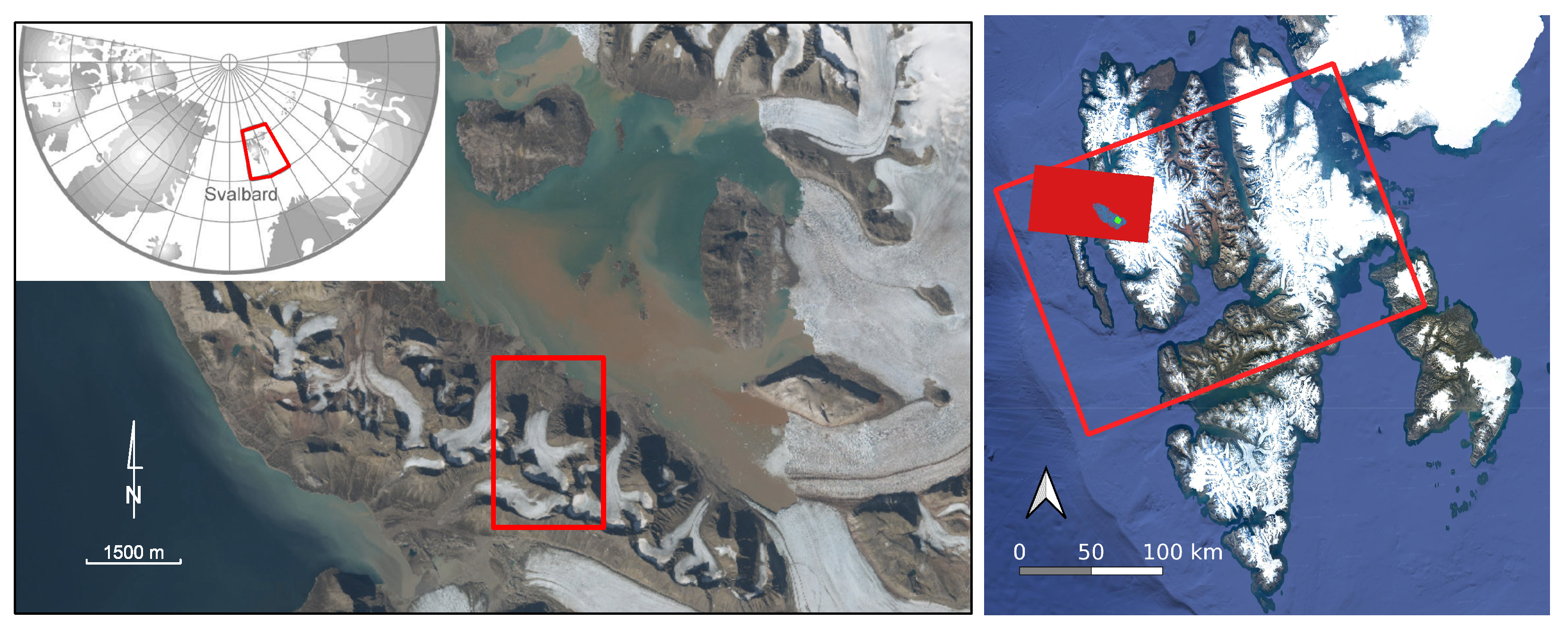
Figure 1. (Left): geographical settings. Spitsbergen (top left) is located between 76.5 and 80°N, with the Brøgger peninsula (background picture: Google, 2020) on the western side of the island between 78.8 and 79°N. The Austre Lovén glacier basin is highlighted with the red rectangle. (Right): Spitsbergen overlaid with the area covered by one Sentinel-1 spaceborne RADAR dataset. The red rectangle line outlines the dataset provided by the European Space Agency as interferometric wide swath collected over land, with the filled red rectangle restricted to a single burst of a single swath (see text for the definition of these terms) covering the Brøgger peninsula (blue). The Austre Lovén glacier is highlighted as the green dot in the eastern part of Brøgger peninsula.
Remotesensing 15 01858 g001
Figure 2. Top-left: automated digital cameras have been installed around the glacier basin for continuous, year-long observation of the snowpack and deducing the FSC from digital image processing. Top-middle and -right: area covered by two cameras until 2017; in 2019, a new camera was setup at the top of the highest summit in order to observe both the glacier snout and the proglacial area. These data are analyzed in this paper. Bottom: sample images from the 2017 position (green viewshed) emphasizing the challenge of azimuthal projection of the oblique-view pictures despite the camera being located on one of the most elevated points of the basin, and differentiating ice and snow covered areas under natural illumination.
Remotesensing 15 01858 g002
Figure 3. Comparison of the raw image acquired by the oblique-view automated camera (top-left), the orthorectified image with the manual delineation of the snow–ice limit (bottom-left) and (right) the Sentinel-1 RADAR-reflected intensity map displayed after applying a binary threshold, with blue the strongly reflecting areas and red the strongly absorbing areas. Top data were collected 10 July 2017 and bottom data were collected 3 August 2017. The fractional snow cover limit was delineated on the oblique-view image and displayed on the RADAR maps for comparison. Bottom: principle of the monoplotting processing technique used for projecting the fractional snow cover limit (red line on the left images) on an azimuthal view map.
Remotesensing 15 01858 g003
Figure 4. Comparison of the microwave reflectivity map (blue for strong reflected power associated with dry snow and ice, red for low reflectivity associated with wet snow) over the Austre Lovén glacier, with oblique-view fractional snow cover maps resulting from oblique-view image processing (top row). Bottom: evolution of the reflectivity along the central line (pink line on each RADAR map) at the same date as each Sentinel-1 RADAR map. The highest cirque is at distance 0 and the moraine at distance 3500 m, with the snow–ice limit altitude rising during the melt season as observed with the progression from low reflectivity (blue, wet snow) to high reflectivity (yellow, dry snow and first and later dry ice). The color coding over the bottom map matches the frame color around each RADAR dataset.
Remotesensing 15 01858 g004
Figure 5. Snow cover evolution deduced from oblique-view ground-based pictures generated by monoplotting and then mapped on a DEM for azimuthal mosaicing (top), and meteorological proxies observed in Ny-Ålesund, air temperature, snow depth and and precipitations, matching the sharp snowpack evolution dates. Dates in the top images are indicated in YYMMDD format with YY the year, MM the month and DD the day.
Remotesensing 15 01858 g005
Figure 6. Evolution between 11 July (left) and 18 July (right) 2017 of the snowpack as observed from the spaceborne Sentinel-2 multispectral imaging sensor. The FSC boundaries were drawn from the ground-based pictures collected 7 (blue), 14 (pink) and 22 (yellow) July. The green boundary outlines the glacier basin. The extent of both snow cover fraction using both techniques seems consistent.
Remotesensing 15 01858 g006
Figure 7. Comparison of the spaceborne multispectral image acquisition from Sentinel-2 (left, collected 18 July 2021 with dark areas identified as bare ice in the lower part of the glacier or water-soaked snow in the upper part, and bright areas as snow) and the RADAR reflectivity map at similar polarization (HH) from spaceborne microwave RADAR Sentinel 1A (right, collected 22 July 2017). Blue indicates strong reflected microwave intensity and red low reflected intensity on the binary map of the RADAR backscattered power map (right). Notice how some of the fine structures along the ice–snow limit on the multispectral image (left) are also visible on the RADAR image (right).
Remotesensing 15 01858 g007
Figure 8. Comparison of the Sentinel-1 microwave reflectivity maps (top two rows, VV and HH polarizations) with Sentinel-2 multispectral imaging (second row from bottom), and ground-based cameras (bottom). The magnified areas on the right-most Sentinel-2 image highlight some dark (wet) features visible at the beginning of the melt season as described in the text.
Remotesensing 15 01858 g008
Figure 9. (A) Run-offs at the interface between the glacier surface and the snowpack: the water system is active with significant outflows due to the snowpack melting, while the snowpack depth is several centimeters deep. (B) When the snowpack is water-saturated, it turns into water immediately, with only a small grounding pressure when walking on the snow. This phenomenon is know as “snow swamp” and gives a significant quantity of running water all at once. This short duration state of transition is clearly identifiable on RADAR images. In all images, blue indicate highly microwave reflective areas and red is highly absorbing (low reflection) areas.
Remotesensing 15 01858 g009
Figure 10. Comparison of the FSC limit deduced from ground-based oblique-view picture analysis (yellow line) and the reflectivity map of the Sentinel-1 data collected the same date (left). The discrepancy between the optical analysis and microwave reflectivity is highlighted on the original picture (right), emphasizing the complementarity of the two measurement techniques because some dark areas associated with bare ice during the ground-based picture analysis are still covered with snow patches detected as strongly absorbing (wet) regions by the spaceborne RADAR (blue dashed line).
Remotesensing 15 01858 g010
Disclaimer/Publisher’s Note: The statements, opinions and data contained in all publications are solely those of the individual author(s) and contributor(s) and not of MDPI and/or the editor(s). MDPI and/or the editor(s) disclaim responsibility for any injury to people or property resulting from any ideas, methods, instructions or products referred to in the content.