Article

A Non-Uniform Interrupted-Sampling Repeater Jamming Method for Intra-Pulse Frequency Agile Radar

Department of Remote Sensing Science and Technology, Xidian University, Xi’an 710071, China
*
Author to whom correspondence should be addressed.
Remote Sens. 2023, 15(7), 1851; https://doi.org/10.3390/rs15071851
Submission received: 4 March 2023 / Revised: 23 March 2023 / Accepted: 28 March 2023 / Published: 30 March 2023

Abstract

:
The existing research proposes an intra-pulse frequency agile radar waveform with “active” anti-jamming characteristics. It uses the discontinuity and periodicity of the interrupted-sampling repeater jamming and combines the anti-jamming algorithm to effectively suppress interrupted-sampling repeater jamming. In order to improve the jamming effectiveness of the interferer for the intra-pulse frequency agile waveform, this paper proposes to jam the intra-pulse frequency agile radar by using a non-uniform interrupted-sampling and forwarding method under parameter constraints. The proposed method first obtains the sub-pulse width of the intra-pulse frequency agile radar waveform by parameter estimation of the intercepted intra-pulse frequency agile radar signal through time–frequency ridge extraction and wavelet transform. Then, we construct non-uniform interrupted-sampling repeater jamming based on sub-pulse width constraint interference parameters. Theoretical analysis and results show that the non-uniform interrupted-sampling forwarding under parameter constraints makes it challenging to suppress interference in multiple domains, such as the time–frequency and pulse compression domain for intra-pulse frequency agile radar, which significantly improves the jamming capability of the jammer for intra-pulse frequency agile radar.

Graphical Abstract

1. Introduction

Various jamming methods have emerged with the rapid development of electronic jamming technology. Among them, digital radio frequency memory (DRFM) [1] technology has been widely used in electronic jamming systems [2,3,4]. Interrupted-sampling repeater jamming (ISRJ) based on digital radio frequency memory can sample and forward the intercepted signal multiple times in a pulse and use the matched filtering characteristics of pulse compression radar to form a realistic coherent false target string to cover the real target. It dramatically reduces the target detection probability of radar. It can produce a better jamming effect for conventional radar [5,6,7].
In recent years, in order to counter the ISRJ based on DRFM, many radar anti-jamming methods have emerged [8,9,10,11,12,13,14,15,16,17,
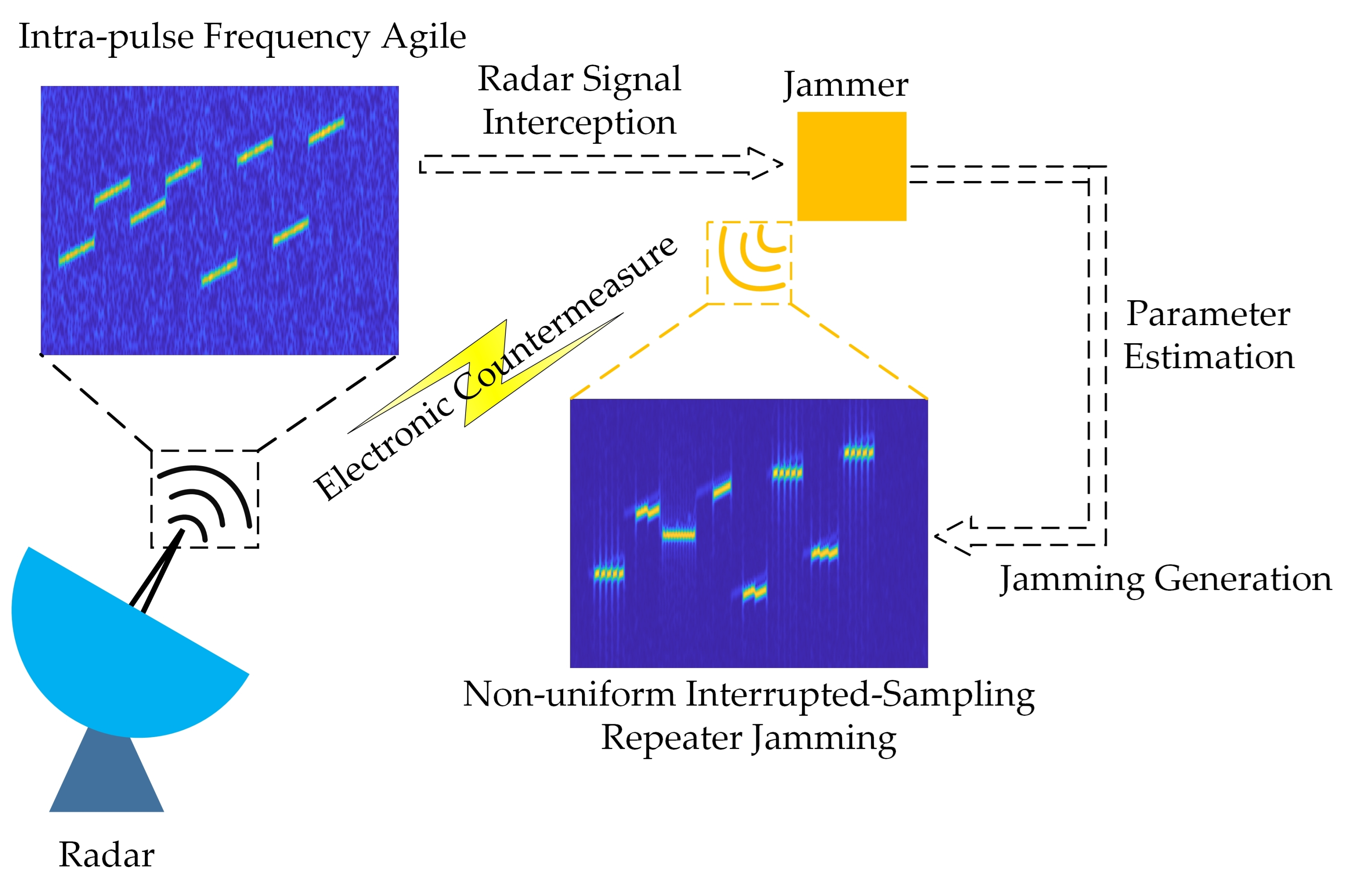
18]. As one of the many anti-jamming technologies, the intra-pulse frequency agile technology, with its superior jamming suppression performance, has seriously reduced the jamming efficiency of the ISRJ. For ISRJ, the intra-pulse frequency agile radar uses its “active” jamming countermeasures advantage and combines the anti-jamming algorithm to extract jamming information in multiple domains and suppress it. Ref. [19] utilizes the orthogonality between the sub-pulses in the pulse, projects the time–frequency distribution in the time dimension through a short-time Fourier transform, extracts the threshold of the echo signal, and suppresses the interference of the time–frequency distribution. Ref. [20] uses the intra-pulse agile waveform to improve the characteristic difference between the target echo signal and the jamming signal, extracts the jamming in the time domain, and then extracts the target signal through the narrowband filter in the fractional Fourier domain. Refs. [21,22] make the radar signal orthogonal to the jamming signal through intra-pulse frequency agile and suppresses the jamming signal during matched filtering. Therefore, ISRJ has been unable to effectively counter various anti-jamming methods based on intra-pulse frequency agile radar.
Based on ISRJ, domestic and foreign scholars have researched non-uniform interrupted-sampling repeater jamming (NUISRJ) and proposed to analyze and optimize jamming pulse compression output results [23]. Ref. [24] interferes with space–time adaptive processing (STAP) through a non-uniform interrupted-sampling repeater and has achieved an excellent jamming effect.
There are increasing studies on suppressing ISRJ based on intra-pulse frequency agile radar. How to effectively counteract intra-pulse frequency agile radar has become a problem. Optimizing and improving the existing jamming, and thus improving the jamming effect, is an effective idea in the current research of jamming methods [25,26]. This paper uses this research idea to optimize the ISRJ based on the intra-pulse frequency agile radar characteristics. Based on the analysis of the characteristics of intra-pulse frequency agile radar and the existing theoretical study of non-uniform interrupted-sampling repeater jamming (NUISRJ), a NUISRJ generation method based on parameter constraints is proposed. This method makes it difficult to suppress interference in multiple domains, such as the time–frequency and pulse compression domains for intra-pulse frequency agile radar. At the same time, it is difficult for radar to accurately sense the sampling width and other interference parameters of NUISRJ compared with ISRJ, which dramatically increases the difficulty of countering jamming. The main contributions of this paper are summarized as follows:
  • We derive the target echo signal of the intra-pulse frequency agile radar under NUISRJ, and then analyze its time–frequency domain and pulse compression domain characteristics;
  • For the intra-pulse frequency agile radar, we use the short-time Fourier transform and Harr wavelet transform to estimate the sub-pulse width of the intra-pulse frequency agile radar, providing conditions for the next step of NUISRJ parameter constraints;
  • We propose the conditions for effective jamming of the intra-pulse frequency agile radar and propose the specific steps for generating NUISRJ under parameter constraints;
  • Finally, in the experimental verification stage, we analyze the interference performance of the NUISRJ with parameter constraints proposed in this paper. The simulation results show that the method proposed in this paper can effectively jam the intra-pulse frequency agile radar and make many jamming suppression methods invalid, significantly reducing the detection probability of radar.
The rest of the article is organized as follows. Section 2 of the article briefly introduces the operating principles of NUISRJ and intra-pulse frequency agile radar. It establishes the mathematical model of the intra-pulse agile radar echo signal under NUISRJ conditions. Section 3 of the article analyses the time–frequency distribution and pulse compression results of the intra-pulse frequency agile radar echo signal under NUISRJ. It proposes the NUISRJ generation steps and interference parameter constraint methods. Section 4 of the article gives several numerical simulation experiments to verify the proposed NUISRJ under the parameter constraint. Finally, Section 5 of the article concludes the whole article.

2. Signal Model

In this section, we derive the signal model of NUISRJ, intra-pulse frequency agile radar. Then, the signal model of the intra-pulse frequency agile radar echo under NUISRJ is developed. This section provides the basis for analyzing the pulse compression results of the echo signal and for parameter constraints on NUISRJ.

2.1. Non-Uniform Interrupted-Sampling Repeater Jamming Model

This section derives the intra-pulse frequency agile radar signal model, and subsequently builds the intra-pulse frequency agile radar echo signal model under NUISRJ based on the model in this section.
NUISRJ samples the intercepted signal at a random length and forwards it at a random quantity, and Figure 1 shows its generation [23].
A total of K non-uniform interrupted-sampling of the radar signal with pulse width T, assuming that the width of each sample is τ k , and the number of transmissions after each sample is m k ; then, the total time for the kth sample forwarding to generate interference can be expressed as
T j k = m k + 1 τ k , k = 1 , 2 , , K
The time of the kth sample gate can be expressed as
T k = 0 , k = 1 l = 1 k T j k , 1 < k < K
The non-uniform interrupted-sampling pulse signal for the intercepted signal has multiple sample gates of different lengths, and the kth sample gate signal can be expressed as
r k t = rect t τ k δ t T k T j
where ⊗ denotes the convolution operation and T j denotes the interferer sampling time delay; the door signal can be expressed as
r e c t t τ k = 1 , 0 t τ k 0 , e l s e
Assuming that the intercepted radar transmit pulse signal by the jammer is x ( t ) , the intercepted signal is sampled non-uniformly, interruptedly, and the sampled signal obtained by sampling the kth sampling gate can be expressed as
x s k t = r k t x t = x t rect t τ k δ t T k T j
After repeated forwarding of the kth sample signal, it can be expressed as
x s s k t = m = 1 m k x t m τ k rect t τ k δ t m τ k T k T j
In the range of the intercepted signal pulse width T, the jamming signal of the non-uniform interrupt sampling repeater is the accumulation of K forwarded signals; so, the total interference signal can be expressed as
J t = A j k = 1 K x s s k t = k = 1 K m = 1 m k x t m τ k rect t τ k δ t m τ k T k T j
where A j indicates the interference signal amplitude.

2.2. Intra-Pulse Frequency Agile Radar

This section derives the intra-pulse frequency agile radar signal model, and subsequently builds the intra-pulse frequency agile radar echo signal model under NUISRJ based on the model in this section.
The intra-pulse frequency agile is to divide the radar signal single pulse into multiple sub-pulses, and the sub-pulse carrier frequency changes randomly, which has the characteristic of frequency domain discontinuity and can realize the alternating cover between sub-pulses. As shown in Figure 2, assume that the radar transmits a total of N pulses with a pulse width of T p , pulse repetition interval of T r , and a bandwidth of B; each pulse contains sub-pulses with a width of T s = T p / S and a sub-pulse bandwidth of B s = B / S ; and the waveform of each sub-pulse is linearly frequency modulated [19,20].
The Sth sub-pulse within the pulse can be expressed as
x s u b t , s = rect t ( s 1 ) T s T s e j 2 π f 0 + b s Δ f t e j π μ t s 1 T s 2
where μ s = B s / T s is the sub-pulse tuning frequency, b ( s ) is the sub-pulse frequency code, Δ f is the sub-pulse minimum frequency interval, and f 0 is the radar carrier frequency.
Assuming a target detected by radar, the initial radial distance of the target is R and the echo of the intra-pulse frequency agile signal received by the radar can be expressed as
x t = σ s = 1 S rect t s 1 T s γ T s e j 2 π f 0 + b s Δ f t γ e j π μ t s 1 T s γ 2
where γ = 2 R / c denotes the target echo time delay of the pulse and σ is the scattering coefficient of the target.

2.3. Radar Echo Signal

The interferer intercepts the intra-pulse frequency agile signal shown in Figure 2 and performs NUISRJ on it, and the jamming signal received by the radar is
J t = A j k = 1 K m = 1 m k s = 1 S rect t s 1 T s γ m τ k T s · e j 2 π f 0 + b s Δ f t γ m τ k e j π μ t s 1 T s γ m τ k 2 rect t m τ k T k T j γ τ k
Under NUISRJ, the echo pulse sequence signal received by the radar can be expressed as
S t = x t + J t + n t
where n ( t ) represents additive Gaussian white noise.
S t = σ s = 1 S rect t s 1 T s γ T s e j 2 π f 0 + b s Δ f t γ e j π μ t s 1 T s γ 2 + A j s = 1 S k = 1 K m = 1 m k rect t γ m τ k s 1 T s T s rect t γ m τ k T k + T j τ k · e j 2 π f 0 + b s Δ f t γ m τ k e j π μ t s 1 T s γ m τ k 2 + n t

3. Jamming Generation Process and Analysis

For the traditional ISRJ, there are many ways to suppress it. First, by sensing the ISRJ sampling width, the frequency agile signal in the pulse is designed and generated so that the sub-pulse width is consistent with the ISRJ sampling width. The separability of the target and the interference is significantly enhanced. Figure 3 shows the time–frequency distribution of the echo signal of the intra-pulse frequency agile radar signal under ISRJ.
Due to the “active” anti-jamming nature of the intra-pulse frequency agile radar waveform, there is a specific gap between the jamming and each sub-pulse in the frequency domain. Therefore, interference suppression methods use narrowband filters for each sub-pulse to filter out the interference and obtain the target echo signal. The discrete distribution of the interference signal and the target echo signal in the frequency domain can reduce the effect on the target echo signal while filtering the interference signal. In addition, the two sub-pulses circled in the echo signal in Figure 3 do not contain the interfering signal due to the discontinuous characteristic of ISRJ in the time domain. Therefore, the undisturbed signal segment of the echo signal can be extracted, and the target can still be detected by segmental pulse compression.
In order to effectively counter the intra-pulse frequency agile radar, this paper obtains the sub-pulse width of the intra-pulse frequency agile signal, constrains the jamming parameters, and generates the non-uniform interrupted sampling and retransmitting jamming to realize the effective jamming of the intra-pulse frequency agile radar. The NUISRJ under the parameter constraint has a good interference effect. At the same time, due to the randomness of non-uniform intermittent sampling and forwarding, it is difficult for the radar party to accurately sense the interference parameters, such as sampling and forwarding width, and design anti-jamming waveforms, which significantly increases the difficulty of fighting against interference.
It can be seen from Figure 4 that under normal jamming conditions, in order to reduce the jamming complexity, the jammer transmits conventional ISRJ signals and identifies whether the intercepted radar signals are intra-pulse frequency agile. The specific radar signal recognition method is not the specific research content of this paper. When the radar signal is judged as an intra-pulse frequency agile signal, the method in this paper is used to estimate the sub-pulse width of the intra-pulse frequency agile radar signal. Then, the jamming parameters of NUISRJ are constrained according to the estimated sub-pulse width, and finally, the jammer generates and transmits NUISRJ under the parameter constraints. The specific process of the core steps is as follows:

3.1. Sub-Pulse Width Estimation

The parameters of the intercepted intra-pulse frequency agile radar signal are estimated to obtain the sub-pulse width of the signal. This paper uses the time–frequency ridge extraction [27,28] combined with wavelet transform to achieve the sub-pulse width estimation of the intra-pulse frequency agile radar signal. The specific steps are shown in Figure 5.
First, the intercepted intra-pulse frequency agile signal is subjected to short-time Fourier transform (STFT) to obtain the time–frequency distribution of the radar signal.
S T F T z ( t , f ) = + z u g u t e j 2 π f u d u
where g ( t ) is the segmented window function of STFT; z ( t ) is the intercepted intra-pulse frequency agile radar signal, which can be expressed as the accumulation of intra-pulse frequency agile signal and Gaussian white noise; and ρ is the attenuation coefficient of radar signal.
z t = ρ s = 1 S x s u b t , s + n t = ρ s = 1 S rect t s 1 T s T s e j 2 π f 0 + b s Δ f t e j π μ t s 1 T s 2 + n t
The time–frequency distribution of the radar signal is obtained through STFT; then, the ridge line is extracted from the time–frequency distribution array. Since the noise in the intercepted radar signal affects the extraction of time–frequency ridges, the noise is filtered using the threshold filter shown in the following equation to ensure that only the intra-pulse frequency agile signal is present in the intercepted signal as much as possible.
S T F T z t , f = S T F T z t , f , ξ S T F T z t , f 0 , e l s e
where ξ = max S T F T z t , f + min S T F T z t , f 2 .
After threshold filtering, ridge lines are extracted from the time–frequency distribution. After extraction, the time–frequency ridge lines of the intra-pulse frequency agile signal can be expressed as
l t = s = 1 S rect t ( s 1 ) T s T s b s Δ f + μ t
Then, carry out Harr wavelet transform on the time–frequency ridge, and the expression of the Harr wavelet transform is
W T m a , b = 1 a + m t ψ * t b a d t
where a is the scale parameter; b represents displacement; and ψ ( t ) is the wavelet base, which can be expressed as
ψ t a = 1 a , a 2 t < 0 1 a , 0 t < a 2 0 , else
Substitute Equation (17) into (18) to obtain the modulus value of the wavelet transform:
W T l a , b = 1 a + l t ψ * t b a d t = 1 a s = 1 S μ 2 b 2 + c s μ a 2 b s Δ f b + Δ , s T s + c s a 2 > b s T s 1 a s = 1 S μ 2 b 2 + c s μ a 2 + b s Δ f b + Δ , s T s > b s T s c s a 2 0 , else
where Δ represents a variable independent of b. Formula (19) calculates the partial derivative of b, which can be expressed as
W T l a , b b = 1 a s = 1 S μ b + c s μ a 2 b s Δ f , s T s + c s a 2 > b s T s 1 a s = 1 S μ b + c s μ a 2 + b s Δ f , s T s > b s T s c s a 2 0 , else
It can be seen from the above formula that when s T s + c s a 2 > b s T s , W T l a , b obtains the maximum value at b = s T s , and when s T s > b s T s c s a 2 , W T l a , b obtains the maximum value at b = s T s . Therefore, the sub-pulse width of the intra-pulse agile radar signal can be obtained by calculating the distance between two adjacent peaks of W T l a , b .

3.2. Interference Parameter Constraint

Through the above analysis, to counter the intra-pulse frequency agile radar, NUISRJ needs to meet two conditions in the time domain and frequency domain. In the time domain, the sub-pulses contain both jamming signals and target echo signals; so, it is impossible to extract the undisturbed sub-pulses. In the frequency domain, the jamming signal frequency should be close to the target echo signal. The sidelobe of the jamming signal should cover the target echo signal as much as possible, and the jamming cannot be filtered. It can be seen from the above Formula (12) that Formula (21) is the real echo signal of the target within the sth sub-pulse and Formula (22) is the NUISRJ signal within the sth sub-pulse. It can be seen that the carrier frequencies of the signals are both f 0 + b s Δ f . Interference in the frequency domain is close to the target echo signal, which requires the presence of both Formulas (21) and (22) within the sth sub-pulse.
rect t s 1 T s γ T s e j 2 π f 0 + b s Δ f t γ e j π μ t s 1 T s γ 2
rect t γ m τ k s 1 T s T s rect t γ m τ k T k + T j τ k e j 2 π f 0 + b s Δ f t γ m τ k e j π μ t s 1 T s γ m τ k 2
Therefore, meeting the above condition can be equivalent to
rect t s 1 T s γ T s rect t γ m τ k s 1 T s T s rect t γ m τ k T k + T j τ k 0 , s 1 T s t s T s
Here, we only consider interference sampling gates in the sub-pulse range. This can be expressed as s 1 T s T k + T j s T s . Under this condition, rect t γ m τ k T k + T j τ k is contained in rect t γ m τ k s 1 T s T s . Thus, we can obtain the following:
rect t γ m τ k s 1 T s T s rect t γ m τ k T k + T j τ k = rect t γ m τ k T k + T j τ k , s 1 T s t s T s
Equation (23) can be further written as
rect t s 1 T s γ T s rect t γ m τ k T k + T j τ k 0 , s 1 T s t s T s
To satisfy Equation (25) above, the following inequality relations must be satisfied:
t γ m τ k T k + T j t s 1 T s γ t s 1 T s γ + T s t γ m τ k T k + T j
Further, the following is obtainable:
s T s m τ k + T k + T j s 1 T s
To sum up, the above conditions are met:
s 1 T s T k + T j s T s , s T s m τ k + T k + T j s 1 T s
Compared with ISRJ, the time–frequency distribution of NUISRJ echo is shown in the figure below. Figure 6 shows the time–frequency distribution of NUISRJ, and its interference parameters meet Equation (28). It can be seen that each sub-pulse contains interference, and the time–frequency characteristic difference between the interference and the target echo signal is minimal. At this time, the intra-pulse frequency agile signal loses the characteristic difference between the target echo signal and the jamming signal and has an excellent jamming effect. Compared with Figure 6a, the interference parameters in Figure 6b do not meet Equation (28), resulting in no interference in the first sub-pulse in the figure, and the echo signal and jamming signal of the second and seventh sub-pulse targets are discrete in the frequency domain.
Therefore, the NUISRJ signal in the received signal can cover the target echo signal well in the frequency and time domains by satisfying Equation (28). Each sub-pulse has an interfering signal and a target echo signal. The difference between the interfering and target signals is so tiny that the radar cannot suppress the interference in the time and frequency domains.

3.3. Pulse Compression Analysis of Echo Signal

For intra-pulse frequency agile radars, pulse compression using matched filters is impossible. Therefore, pulse compression is processed by constructing S sub-matched filters [20]. Next, we will analyze the pulse compression results of the echo signal under NUISRJ. According to Formula (12), the interference signal is down-converted and then processed by subsection pulse compression, which can be expressed as
Y t = s = 1 S k = 1 K m = 1 m k A j e j 2 π b s Δ f t γ m τ k rect t γ m τ k ( s 1 ) T s T s · e j π μ t s 1 T s γ m τ k 2 rect t γ m τ k ( T k + T j ) τ k x s u b * t , s
The pulse compression result of the kth sampling and mth forwarding in the sth sub-pulse can be expressed as
Y s , k , m , t = A j τ k e j π 2 b s Δ f t γ m τ k + μ γ 2 t 2 + 2 m τ k γ + m 2 τ k 2 sinc π μ t m τ k γ
The total pulse compression result of the jamming signal can be expressed as
Y t = s = 1 S k = 1 K m = 1 m k Y s , k , m , t
From Equation (30), it can be seen that after segmented pulse compression, the pulse compression result of the kth sample of the mth forward within the sth sub-pulse has a main flap center of m τ k + γ and an amplitude of A j τ k . The pulse compression amplitude of the target echo signal is related to the signal pulse width. Therefore, to make the NUISRJ pulse compression amplitude cover the target echo signal and reduce the target detection probability, it is necessary to ensure that each sampling width is narrow enough compared with the radar signal pulse width. It can be seen from the above pulse compression results that, unlike ISRJ, NUISRJ will generate a large number of cluttered and dense false targets near the target after segmented pulse compression. In contrast, the ISRJ pulse compression results have strong regularity, and the interference is easily perceived—thus, being targeted and suppressed—which is one of the reasons why NUISRJ is used in this paper.

4. Simulation Experiment

In order to verify the jamming effect of the method proposed in this paper on the intra-pulse frequency agile radar, four sets of simulation experiments are designed in this section, and the simulation software is MATLAB. The first and second groups tested the jamming effect of NUISRJ with two existing suppression methods for the frequency agile radar within the pulse. The third group analyses the influence of NUISRJ on radar detection probability. The fourth group analyses the influence of jamming parameters on the jamming effect of NUISRJ. The radar works in the Ku band, and the frequency agile radar waveform is linear frequency modulation. The specific waveform parameters are shown in Table 1.

4.1. Simulation Experiment 1

Suppose that the radial distance of the target in the scene is 2500 m, the target carries a self-defense jammer, the signal-to-noise ratio (SNR) of the target echo signal is 0 dB, and the jamming-to-signal ratio (JSR) is 20 dB. ISRJ and NUISRJ interfere with the method proposed in Ref. [20]. NUISRJ parameters are shown in Table 2.
In this section, we use the method proposed in Ref. [20] for interference suppression of ISRJ and NUISRJ. This method uses the intra-pulse frequency agile radar to avoid the interference frequency band actively and constructs a narrowband filter bank in the fractional Fourier domain to extract the target signal to achieve the purpose of suppressing interference. The ISRJ and NUISRJ suppression effects were simulated, respectively. The simulation results of anti-ISRJ are shown in Figure 7. Figure 7a shows the intra-pulse frequency agile radar echo signal time–frequency distribution under ISRJ. Figure 7b shows the time–frequency distribution of the intra-pulse frequency agile radar echo signal after ISRJ suppression using the method in Ref. [20]. It can be seen from the results that this method filters out ISRJ very well, and only a real target echo signal exists in the time and frequency domain. Figure 7c shows the pulse compression results of the echo signal before suppressing ISRJ. It can be seen from the results that there is deception interference of false targets in the distance dimension. Figure 7d shows the pulse compression results of the echo signal after suppressing ISRJ. False targets are suppressed; only real targets exist in the distance dimension. In conclusion, this method can effectively suppress ISRJ.
According to the anti-jamming algorithm for intra-pulse frequency agile radar proposed in Ref. [20], we use NUISRJ for jamming and select the jamming parameters in Table 2. Figure 8 shows the simulation results of this method for NUISRJ suppression. Figure 8a shows the time–frequency distribution of the intra-pulse frequency agile radar echo signal under NUISRJ. Figure 8b shows the temporal frequency distribution of the method in Ref. [20] after suppressing the NUISRJ. Since the method finds and filters the interference peaks in the fractional Fourier domain, the interference suppression effect is affected when the fractional Fourier domain interference is mixed with the target real echo signal. It can be seen that the method is less effective in suppressing NUISRJ. It suppresses the target echo signal while suppressing the NUISRJ, and the interference components are still present in some sub-pulses after the interference suppression. Figure 8c shows the pulse compression results of the radar echo signal before NUISRJ suppression. The pulse compression results of NUISRJ are related to the sampling time width and the number of forwarding times.
Comparing Figure 7c with Figure 8c. It can be seen that NUISRJ differs from ISRJ in that NUISRJ can produce more cluttered and dense false target interference after pulse compression. Figure 8d shows the pulse compression results of the radar echo signal after NUISRJ suppression. It can be seen that there is still false target interference in the pulse compression results because the interference component is still present after interference suppression. Comparing Figure 7d with Figure 8d, the target signal pulse compression amplitude is smaller after NUISRJ is suppressed. This is because the interference signal is suppressed along with the real echo signal of the target. Therefore, NUISRJ has a better interference effect for this anti-interference method than ISRJ.

4.2. Simulation Experiment 2

In this section, we use the method proposed in Ref. [19] for interference suppression. The method transforms the echo signal to the time–frequency domains and suppresses the main flap of the interference and the side flap whose amplitude is larger than the target signal by using the maximum value of the target echo signal as the threshold and then transforms the time–frequency domains to the time domain using short-time Fourier inversion. The effects of this method to suppress ISRJ and NUISRJ are simulated, respectively. The results of ISRJ suppression are shown in Figure 9. This method can filter ISRJ in both time–frequency domains. After the transformation to the time domain, the target can be detected after the pulse compression output.
For the intra-pulse frequency agile radar anti-jamming algorithm proposed in Ref. [19], NUISRJ is used for jamming. We choose the jamming parameters in Table 2. The results of this method to suppress NUISRJ are shown in Figure 10 below. Figure 10b shows the time–frequency distribution after interference suppression. Although this method can suppress the interfering signal, the component of NUISRJ covers the target echo signal. Part of the target echo signal is also suppressed while suppressing the interference because the NUISRJ under the parameter constraint covers the real target echo signal in the frequency domain by comparing the pulse compression results before and after interference suppression in Figure 10c,d. Although the method can filter most of the interfering signals, there is a loss of the target signal after interference suppression, which makes it difficult to achieve target detection.

4.3. Simulation Experiment 3

This simulation experiment further analyzes the interference performance of NUISRJ and tests the radar detection probability after suppressing ISRJ and NUISRJ. The radar signal parameters are shown in Table 1. The constant false alarm rate (CFAR) detector detects the results after pulse compression. The false alarm rate is set to P f a = 10 4 , and the SNR before pulse compression is stepped in the range of [−15:−5] dB. The detection probability s variation curve with SNR is shown in Figure 11. The figure shows that the method in Refs. [19,20] can effectively suppress ISRJ. When the SNR is −10 dB, the detection probability is close to 100 % . However, the detection probability of the method in Refs. [19,20] after NUISRJ suppression is low regardless of the signal-to-noise ratio variation. Therefore, the proposed NUISRJ is very effective for intra-pulse frequency agile radar interference, which can significantly reduce the radar detection probability.

4.4. Simulation Experiment 4

We test the interference performance of NUISRJ with different parameters and compare the interference effects with and without the interference parameters, satisfying the conditions of Formula (28). We use the method of Refs. [19,20] to suppress four different groups of NUISRJ during the test. Figure 12 shows the time–frequency distribution of the target echo signal under the four sets of interference. Among them, the NUISRJ under parameters 1 and 3 follows Formula (28).
We have used the method in Refs. [19,20] to suppress the NUISRJ under four interference parameters. Figure 13 shows the pulse compression results of the echo signal after interference suppression. It can be seen that the amplitude of the radar target echo pulse compression results is smaller after interference suppression, with NUISRJ satisfying Formula (24) for the intra-pulse agile radar signal. Therefore, it can be shown that the NUISRJ interference satisfying Formula (24) has a better interference effect. The radar can suppress the target echo signal to a greater extent while suppressing the interfering signal.

5. Conclusions

Existing anti-interference sampling repeater interference methods generate frequency agile waveforms within a pulse by sensing the interference sampling width. Its “active” anti-jamming feature enhances the characteristic difference between the target echo and the interfering signal. At the same time, combined with various interference filtering methods, the radar can effectively suppress ISRJ, significantly reducing interference effects. Based on the existing NUISRJ methods, we analyze the characteristics of NUISRJ and perform parameter estimation of the intercepted NUISRJ radar signals to obtain the sub-pulse widths. Then, we constrain the NUISRJ parameters according to the sub-pulse width to generate random complex and variable NUISRJ, which makes the interference challenging to sense and reject in several domains (e.g., time–frequency domain). The method can effectively interfere with intra-pulse frequency agile radars while being challenging to suppress by multiple anti-jamming algorithms.

Author Contributions

Conceptualization, Z.S. and Y.Q.; methodology, Z.S.; software, Z.S.; validation, Z.L. and Y.Q.; formal analysis, Z.S.; investigation, Z.S.; resources, Y.Q.; data curation, Z.S.; writing—original draft preparation, Z.S.; writing—review and editing, Z.S.; visualization, Z.S.; supervision, Y.Q.; project administration, Y.Q.; funding acquisition, Y.Q. All authors have read and agreed to the published version of the manuscript.

Funding

This work was supported by National Natural Science Foundation of China (61772397).

Data Availability Statement

The data are available to readers by contacting the corresponding author.

Acknowledgments

The author would like to thank the Institute of Advanced Remote Sensing Technology.

Conflicts of Interest

The authors declare no conflict of interest.

Abbreviations

The following abbreviations are used in this manuscript:
DRFMDigital radio frequency memory
ISRJInterrupted-sampling repeater jamming
NUISRJNon-uniform interrupted-sampling repeater jamming
JSRJamming-to-signal ratio
LFMLinear frequency modulation
SNRSignal-to-noise ratio
STFTShort-time Fourier transform

References

  1. Berger, S.D. Digital radio frequency memory linear range gate stealer spectrum. IEEE Trans. Aerosp. Electron. Syst. 2003, 39, 725–735. [Google Scholar] [CrossRef]
  2. Li, C.Z.; Su, W.M.; Gu, H. Improved interrupted sampling repeater jamming based on DRFM. In Proceedings of the 2014 IEEE International Conference on Signal Processing, Communications and Computing (ICSPCC), Guilin, China, 5–8 August 2014; pp. 254–257. [Google Scholar]
  3. Zhang, J.D.; Zhu, D.Y.; Zhang, G. New antivelocity deception jamming technique using pulses with adaptive initial phases. IEEE Trans. Aerosp. Electron. Syst. 2013, 49, 1290–1300. [Google Scholar] [CrossRef]
  4. Zhou, C.; Liu, Q.; Chen, X. Parameter estimation and suppression for DRFM-based interrupted sampling repeater jammer. IET Radar Sonar Navig. 2018, 12, 56–63. [Google Scholar] [CrossRef]
  5. Yuan, H.; Wang, C.-Y.; Li, X.; An, L. A method against interrupted-sampling repeater jamming based on energy function detection and band-pass filtering. Int. J. Antennas Propag. 2017, 2017, 6759169. [Google Scholar] [CrossRef] [Green Version]
  6. Wang, X.S.; Liu, J.C.; Zhang, W.M.; Fu, Q.; Xie, X. Mathematic principles of interrupted sampling repeater jamming (ISRJ). Sci. China Ser. F 2007, 50, 113–123. [Google Scholar] [CrossRef]
  7. Yang, Y.; Zhang, W.M.; Yang, J. Study on frequency-shifting jamming to linear frequency modulation pulse compression radars. In Proceedings of the International Conference on Wireless Communications & Signal Processing, Nanjing, China, 13–15 November 2009; pp. 1–5. [Google Scholar]
  8. Yang, Y.; Zhang, W.M. A cognitive active anti-jamming method based on frequency diverse array radar phase center. Digit. Signal Process. 2021, 109, 102915. [Google Scholar]
  9. Zhou, K.; Li, D.; Su, Y.; Liu, T. Joint design of transmit waveform and mismatch filter in the presence of interrupted sampling repeater jamming. IEEE Signal Process. Lett. 2020, 27, 1610–1614. [Google Scholar] [CrossRef]
  10. Liu, Z.; Quan, Y.; Wu, Y.; Xu, K.; Xing, M. Range and Doppler reconstruction for sparse frequency agile linear frequency modulation-orthogonal frequency division multiplexing radar. IET Radar Sonar Navig. 2022, 16, 1014–1025. [Google Scholar] [CrossRef]
  11. Hanbali, S.B.S. Technique to counter improved active echo cancellation based on ISRJ with frequency shifting. IEEE Signal Process. Lett. 2019, 19, 9194–9199. [Google Scholar]
  12. Quan, Y.H.; Wu, Y.J.; Li, Y.C.; Sun, G.; Xing, M. Range-Doppler reconstruction for frequency agile and PRF-jittering radar. IET Radar Sonar Navig. 2018, 12, 348–352. [Google Scholar] [CrossRef]
  13. Sun, Y.; Zheng, Z.; Wang, W.Q. Phased-MIMO radar with frequency diversity for range-dependent beamforming. Digit. Signal Process. 2020, 106, 102858. [Google Scholar] [CrossRef]
  14. Chen, J.; Wu, W.; Xu, S.; Chen, Z.; Zou, J. Band pass filter design against interrupted sampling repeater jamming based on time-frequency analysis. IET Radar Sonar Navig. 2019, 13, 1646–1654. [Google Scholar] [CrossRef]
  15. Zheng, H.; Jiu, B.; Liu, H. Waveform design based ECCM scheme against interrupted sampling repeater jamming for wideband MIMO radar in multiple targets scenario. IEEE Sens. J. 2022, 22, 1652–1669. [Google Scholar] [CrossRef]
  16. Gong, S.X.; Wei, X.Z.; Li, X. ECCM scheme against interrupted sampling repeater jammer based on time-frequency analysis. Syst. Eng. Electron. 2022, 25, 996–1003. [Google Scholar] [CrossRef]
  17. Zhou, K.; Li, D.X.; Quan, S.N. SAR Waveform and mismatched filter design for countering interrupted-sampling repeater jamming. IEEE Trans. Geosci. Remote Sens. 2022, 60, 1–14. [Google Scholar] [CrossRef]
  18. Duan, J.; Zhang, L.; Wu, Y.F.; Li, Y.C. Interrupted-sampling repeater jamming suppression with one-dimensional semi-parametric signal decomposition. Digit. Signal Process. 2022, 17, 103546. [Google Scholar] [CrossRef]
  19. Zhang, J.Z.; Mu, H.Q.; Wen, S.L.; Li, Y.B. Anti interrupted sampling jamming method based on in pulse step LFM time-frequency analysis. Trans. Beijing Inst. Technol. 2020, 40, 543–551. [Google Scholar]
  20. Liu, Z.X.; Quan, Y.H.; Du, S.Y.; Wu, Y.J.; Sha, M.H.; Xing, M.D. A novel ECCM scheme against interrupted-sampling repeater jamming using intra-pulse dual-parameter agile waveform. Digit. Signal Process. 2022, 129, 103652. [Google Scholar] [CrossRef]
  21. Wei, Z.H.; Liu, Z.; Peng, B.; Shen, R. ECCM Scheme against Interrupted Sampling Repeater Jammer Based on Parameter-Adjusted Waveform Design. Sensors 2018, 18, 1141. [Google Scholar] [CrossRef] [Green Version]
  22. Zhou, C.; Liu, F.F.; Liu, Q.H. An Adaptive Transmitting Scheme for Interrupted Sampling Repeater Jamming Suppression. Sensors 2017, 17, 2480. [Google Scholar] [CrossRef] [Green Version]
  23. Luo, Z.H.; Li, J.B.; Dong, X.Y.; Sun, J.B. Research on Non-uniform Interrupted Sampling Repeater Jamming for Phase Coded Radar. J. Phys. Conf. Ser. 2022, 2209, 012004. [Google Scholar] [CrossRef]
  24. Li, J.; Duan, X.; Li, J.; Bai, P. A Stochastic Simulation Optimization based Range Gate Pull-off Jamming Method. Syst. Electron. 2023, 12, 152. [Google Scholar]
  25. Wang, Y.H.; Zhang, T.X.; Kong, L.J.; Ma, Z.J. A stochastic simulation optimization based range gate pull-off jamming method. IEEE Trans. Evol. Comput. 2022; 1, early access. [Google Scholar]
  26. Wang, Y.H.; Zhang, T.X.; Kong, L.J.; Ma, Z.J. Strategy Optimization for Range Gate Pull-Off Track-Deception Jamming under Black-Box Circumstance. IEEE Trans. Aerosp. Electron. Syst. 2023; 1–12, early access. [Google Scholar]
  27. Colominas, M.A.; Meignen, S.; Pham, D.H. Fully Adaptive Ridge Detection Based on STFT Phase Information. IEEE Signal Process. Lett. 2020, 27, 620–624. [Google Scholar] [CrossRef]
  28. Aoi, M.; Lepage, K.; Lim, Y.; Eden, U.T.; Gardner, T.J. An Approach to Time-Frequency Analysis With Ridges of the Continuous Chirplet Transform. IEEE Trans. Signal Process. 2015, 63, 699–710. [Google Scholar] [CrossRef]
Figure 1. Schematic diagram of NUISRJ.
Remotesensing 15 01851 g001
Figure 2. Intra-pulse frequency agile waveform time–frequency diagram.
Remotesensing 15 01851 g002
Figure 3. Time–frequency distribution of echo signal of intra-pulse frequency agile signal under ISRJ.
Remotesensing 15 01851 g003
Figure 4. NUISRJ generation process.
Remotesensing 15 01851 g004
Figure 5. Sub-pulse width estimation process.
Remotesensing 15 01851 g005
Figure 6. The time–frequency distribution of NUISRJ with and without satisfying the conditions (28): (a) satisfying Formula (28), (b) unsatisfactory Formula (28).
Remotesensing 15 01851 g006
Figure 7. Suppression effect of Ref. [20] on ISRJ: (a) time–frequency distribution before suppression, (b) time–frequency distribution after suppression, (c) pulse compression before suppression, (d) pulse compression after suppression.
Remotesensing 15 01851 g007
Figure 8. Suppression effect of Ref. [20] on NUISRJ: (a) time–frequency distribution before suppression, (b) time–frequency distribution after suppression, (c) pulse compression before suppression, (d) pulse compression after suppression.
Remotesensing 15 01851 g008
Figure 9. Suppression effect of Ref. [19] on ISRJ: (a) time–frequency distribution before suppression, (b) time–frequency distribution after suppression, (c) pulse compression before suppression, (d) pulse compression after suppression.
Remotesensing 15 01851 g009
Figure 10. Suppression effect of Ref. [19] on NUISRJ: (a) time–frequency distribution before suppression, (b) time–frequency distribution after suppression, (c) pulse compression before suppression, (d) pulse compression after suppression.
Remotesensing 15 01851 g010
Figure 11. Under different JSRs, the detection probability after jamming suppression changes with SNR: (a) JSR = 10 dB, (b) JSR = 20 dB. (blue and yellow) [21], (red and cyan) [22].
Remotesensing 15 01851 g011
Figure 12. NUISRJ time–frequency distribution under different parameters: (a) parameter 1, (b) parameter 2, (c) parameter 3, (d) parameter 4.
Remotesensing 15 01851 g012
Figure 13. Comparison of pulse compression results after using different methods to suppress NUISRJ: (a) Ref. [20]’s method, (b) Ref. [19]’s method.
Remotesensing 15 01851 g013
Table 1. Parameters of the intra-pulse frequency agile radar.
ParameterValue
Sampling rate f s 200 MHz
Pulse repetition period T r 40 μs
Carrier frequency f 0 14 GHz
Number of sub-pulses S8
Intra-pulse frequency hopping interval Δ f 6 MHz
Sub-pulse bandwidth B s 6 MHz
Sub-pulse pulse width T s 6 μs
Table 2. Parameters of non-uniform interrupted-sampling repeater jamming.
k m k τ k
151 μs
222 μs
3110.5 μs
413 μs
522 μs
651 μs
731.5 μs
851 μs
Disclaimer/Publisher’s Note: The statements, opinions and data contained in all publications are solely those of the individual author(s) and contributor(s) and not of MDPI and/or the editor(s). MDPI and/or the editor(s) disclaim responsibility for any injury to people or property resulting from any ideas, methods, instructions or products referred to in the content.

