Article

A Novel Intrapulse Beamsteering SAR Imaging Mode Based on OFDM-Chirp Signals

College of Electronic Science and Technology, National University of Defense Technology, No. 109 Deya Road, Changsha 410073, China
*
Author to whom correspondence should be addressed.
Remote Sens. 2024, 16(1), 126; https://doi.org/10.3390/rs16010126
Submission received: 19 October 2023 / Revised: 17 December 2023 / Accepted: 25 December 2023 / Published: 28 December 2023
(This article belongs to the Special Issue Radar and Sonar Imaging and Processing IV)

Abstract

:
The multiple-input multiple-output synthetic aperture radar (MIMO SAR) system has developed rapidly since its discovery. At the same time, the low-disturbance and high-gain requirements of the MIMO system are continuing to increase. Through the application of digital beamforming (DBF) techniques, the multidimensional waveform encoding (MWE) technique can play a key role in MIMO systems, which can greatly improve the system’s performance, especially the multi-mission capability of radar. Intrapulse beamsteering in elevation is a typical form of multi-dimensional waveform encoding which can greatly improve the transmitting efficiency and multi-mission performance of radar. However, because of the high sensitivity of the DBF technique to height, there is significant deterioration in performance in the presence of terrain undulations. The OFDM (Orthogonal Frequency Division Multiplexing) technique is widely used in communication. Due to the similarity of radar and communication systems and the great waveform diversity of OFDM signals, the OFDM radar has recently begun to emerge as a new radar system, simultaneously, the orthogonality of OFDM signals is in the time and frequency domains, and is not affected by terrain undulation. So, this paper proposes a novel radar mode combining intrapulse beamsteering in elevation and OFDM-Chirp signals, that is, the combination of “beam orthogonality” and “waveform orthogonality”, which can greatly improve the performance and fault tolerance to interference signals. In this manuscript, the system working mode and signal processing flow are introduced in detail, and simulations for both point targets and distributed targets are carried out to verify the feasibility of the proposed mode. Simultaneously, a comparison experiment is carried out, which shows the high level of fault tolerance to terrain undulation and the high potential of the proposed radar mode in Earth observation.

Graphical Abstract

1. Introduction

Synthetic aperture radar (SAR) has been widely used as it has the advantages of all-weather, all-day capabilities, a wide swath, and high resolution. However, because of the constraint on the minimum area of the antenna, the conventional SAR cannot achieve a high azimuth resolution and wide swath simultaneously. The concept of MIMO was first proposed in the communication engineering field in order to solve the multi-path effect [1]. At the same time, in the field of radar, many researchers have paid increasing attention to radar systems with multiple antennas or multiple apertures, called MIMO radar [2,3,4]. The MIMO concept is also highly attractive for SAR systems because a MIMO SAR system with multiple antennas or multiple apertures can obtain more equivalent transmitting and receiving channels than a conventional SAR system in condition of the same PRF (Pulse Repetition Frequency); this offers the possibility of solving the contradictions between high azimuth resolution and wide swath in elevation [4,5,6]. With the development of MIMO radar systems, the processing of the receiving end becomes the key problem. Many new technologies have been proposed recently, such as the new imaging scheme based on Loffeld’s bistatic formula for a multi-receiver SAR system, which provides a better image compared to the phase center approximation method [7]. Wang et al. proposed an innovative waveform separation scheme based on echo compression. The transmitters are required to radiate alone several times in a synthetic aperture to acquire their private inner-aperture channels, then the energy of each waveform can be concentrated by the matched-filtering of the mixed echoes with the sensed echoes [8].
DBF on a receiver is a powerful method for waveform separation and suppression which can play an important role in MIMO SAR system [9]. For the DBF technique, the antenna at the receiving end is divided into several sub-apertures. Through constructing different weighting matrices, the echoes received by each sub-aperture can be weighted to form different beams that point in the direction from which we want to obtain the signal and suppress the direction we do not want. The DBF technique can be used not only in the azimuth but also in the elevation direction. After waveform separation using the DBF technique, the mixed echoes are divided into several independent signals from different directions, so here the imaging processing methods for conventional SAR can be applied to them. Based on the rapid application and perfection of the DBF technique [9], the innovative concept of MWE was proposed [10]. The use of the MWE technique in transmitting signals can bring great changes to a MIMO SAR system. The transmitting signals can be flexibly coded in the time, frequency, and space domains, even at higher dimensions such as the polarization information dimension [11,12,13]. The combination of the DBF technique and MWE technique can further exploit the degrees of freedom, which can greatly enhance the system performance, especially the ability of multi-mode working which can provide the possibility for MWE SAR realization [4,5,6,9,10,11,12,13,14,15,16,17,18]. Intrapulse beamsteering at elevation is one typical example of MWE, which can obtain a wide swath width and high azimuth resolution simultaneously. It can also greatly reduce the requirement of transmission power and PRF [10]. The detailed working principle and method will be introduced in the following chapters. However, there are also some drawbacks. An obvious disadvantage is that the fault tolerance to the height error and terrain undulation is low. Considering this problem, we try to apply OFDM-Chirp signals to the intrapulse beamsteering system, which will be introduced in detail in the following chapters.
The OFDM (Orthogonal Frequency Division Multiplexing) technique is widely used in the field of high-speed wireless communication due to its excellent anti-frequency selective fading performance [19]. Because of the similarity between radar systems and communication systems, Krieger proposed the concepts of short-term shift-orthogonal (STSO) waveform and orthogonal frequency-division modulation chirp (OFDM-Chirp) waveform, and then verified the consistency between these two waveforms in DBF at receiving [10].Then, in 2013, J. Kim proposed a new space-borne MIMO SAR system that applied the OFDM-Chirp signals, and the modulation and demodulation processing methods for the OFDM-Chirp signals were given in reference [20].
To solve the problem of the high sensitivity of the DBF technique to the height error, this manuscript introduces an innovative SAR mode with the combination of OFDM-Chirp signals and intrapulse beamsteering, referring to the combination of waveform orthogonality and beam orthogonality, which could further enhance the system performance and robustness to interference factors such as terrain undulation. We have carried out preliminary feasibility verification and simple point target verification on this mode [21]. In this manuscript, we further elaborate this idea in more detail, including the establishment and perfection of the signal model, experimental verification of distributed target simulation based on the improved ICS algorithm we proposed, and most importantly, a series of controlled experiments with random terrain undulation are carried out to demonstrate the advantages and application potential of the proposed mode compared with the conventional intrapulse beamsteering system using LFM signal. Section 1 provides a brief introduction, which puts forward our research motivation and research content; Section 2 introduces the working mode and the transmission mode of the intrapulse beamsteering system and presents the simple signal model; Section 3 proposes the new mode in which the OFDM-Chirp signals are applied to the intrapusle beamsteering system and presents the specific signal processing flow; Section 4 shows the simulation results of both point targets and distributed targets, which prove the feasibility and advantages of the proposed mode. Section 5 presents a detailed discussion and analysis of the simulation results. Section 6 summarizes the work, the related problems, and the directions of further research.

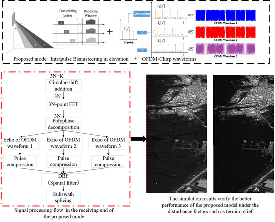
2. Intrapulse Beamsteering in Elevation

2.1. Principles

Intrapulse beamsteering is a typical example of multidimensional waveform encoding (MWE), and a type of DBF in transmitting. The beam irradiates in different directions at different times within the pulse. It is actually a concept of “beam direction control”, through which high-gain beams and a wide swath can be achieved simultaneously.
As we can see in Figure 1 below, the wide swath is separated into several small subswaths. Simultaneously, several narrow beams are transmitted within one transmitting pulse, with each beam corresponding to a subswath. If the beams scan from the far end to the near end of whole swath and emit different waveforms successively, the echoes from different subswaths will be mixed when received, which will result in range ambiguity.
Through the use of DBF in elevation on a receiver, we can separate the mixed echo signal from different subswaths into several independent echoes. During the DBF processing, the differences in the direction of arrival (DOA) of different subswaths are utilized to construct a spatial filter. Therefore, we can obtain the echoes from the useful directions and suppress echoes from the interfering directions.
Due to its special working mode and principle, the intrapulse beamsteering system has many advantages:
  • Echoes from different subswaths overlap at the receiving end, leading to a substantial reduction in the time width of receiving window, so that the duty ratio of the transmitting signal can be increased, thereby improving both the echo SNR (Signal-to-Noise Ratio) and the working distance of the system;
  • Due to the freedom of transmission, signals with different bandwidths can be transmitted for different subpulses, therefore, that different subswaths can have different range resolutions, which can enhance the system’s multi-range-resolution observation ability;
  • It uses array weighting to form narrow beams in the elevation direction, so the gain of each narrow beam is higher and then the transmission power requirements for the transmitter can be reduced;
  • Through phase weighting, the gains of different directions in each subswath are almost uniform, and the gain attenuation at the edge of the swath is alleviated.
Furthermore, the intrapulse beamseering technique can also be combined easily with the azimuth multi-channel mode to improve azimuth performance.

2.2. Signal Model

Here we take three subswaths as examples, assuming that three subpulses are transmitted in a PRI, each one corresponding to a subswath. The echoes of different subpulses will overlap at the receiving end. After waveform modulation, the entire transmitting signal can be written as follows [13]:
s ( t ) = [ p 1 ( t ) k = δ ( t k T r ) + p 2 ( t ) k = δ ( t T d k T r ) + p 3 ( t ) k = δ ( t 2 T d k T r ) ] exp ( j 2 π f c t )
where t is the time variable; p 1 ( t ) , p 2 ( t ) , and p 3 ( t ) are the complex baseband forms of the three transmitting pulses, respectively, which correspond to pulses A, B, and C in Figure 1; T d is the time interval between transmitting sub-pulses; T r is the PRI; and f c is the carrier frequency. It should be noted here that because our research focuses on intrapulse beamsteering in elevation, partial azimuth characteristics in modeling are ignored for the sake of simplicity.
Then, after waveform demodulation and matching filtering, the signal of the i-th subpulse in the k-th pulse repetition period received by the first elevation channel is given by
s k , i ( t ) = g k , i ( τ ) exp ( j 2 π f c τ ) p i , c o m p ( t τ ( i 1 ) T d k T r ) d τ ρ τ 2 ρ τ 2 g k , i ( t τ ( i 1 ) T d k T r ) p i , c o m p ( τ ) d τ
where p i , c o m p ( t ) is the form of p i ( t ) after pulse compression with mainlobe width ρ τ , g k , i ( τ ) is the ground reflectivity functions of the first elevation channel in elevation for different subpulses, and g k , i ( τ ) is the extended forms of g k , i ( τ ) after demodulation, which can be written as
g k , i ( τ ) = g k , i ( τ ) exp ( j 2 π f c τ ) = A T , i ( τ ) A R , i ( τ ) σ i ( τ ) exp ( j 2 π f c τ )
where A T ( τ ) and A R ( τ ) are the transmitting and receiving antenna patterns. A T ( τ ) can be considered to be the same for each channel and A R ( τ ) is determined by the angle θ 1 ( τ ) , which is the angle between the receiving slant range of the first channel and the array antenna, as illustrated in Figure 2; τ is the roundtrip time delay to the first receiving channel in elevation.
Similarly, the echoes of the i-th subpulse in the k-th period received by the m-th elevation channel are given by the following:
s k , i , m ( t ) = g k , i , m ( τ ) exp ( j 2 π f c τ ) p i , c o m p ( t τ ( i 1 ) T d k T r ) d τ ρ τ 2 ρ τ 2 g k , i , m ( t τ ( i 1 ) T d k T r ) p i , c o m p ( τ ) d τ
The brief geometric model is shown in Figure 2; here, we assume that there are M subapertures (receiving channels) in the elevation direction.
R R , 1 is the slant range from the first receiving channel to the scattering point on the ground and R R , m is the slant range from the m-th channel to the scattering point. Under the far-field approximation,
θ m ( τ ) θ 1 ( τ ) = θ ( τ )
R R , m R R , 1 + ( m 1 ) d r sin ( θ ( τ ) θ c )
where dr is the length of antenna sub-aperture, θ ( τ ) is the elevation angle between the receiving slant range of the reference channel (the first receiving channel) and the array antenna, and θ c is the off-nadir angle of the antenna, which is 90 in Figure 2. Therefore, the difference in the roundtrip time delay between the m-th receiving channel and the reference receiving channel (the first receiving channel) is expressed as:
Δ τ m ( θ ( τ ) ) ( m 1 ) d r sin ( θ ( τ ) θ c ) c
Due to the approximation of Equations (5)–(7), we can obtain:
g k , i , m ( τ ) = A T , i , m ( τ ) A R , i , m ( τ ) σ i ( τ ) exp ( j 2 π f c ( τ + Δ τ m ( θ ( τ ) ) ) ) g k , i ( τ ) exp ( Δ τ m ( θ ( τ ) ) )
so that the echoes of the i-th subpulse received by the m-th array element can be rewritten as follows:
s k , i , m ( t ) = ρ τ 2 ρ τ 2 g k , i , m ( t τ ( i 1 ) T d k T r ) p i , c o m p ( τ ) d τ exp ( j 2 π f c Δ τ m ( θ ( t τ ( i 1 ) T d k T r ) ) ) s k , i ( t )
Notice that an approximation is made whereby the trivial variation of Δ τ m ( θ ( t τ ( i 1 ) T d k T r ) ) within one range cell is ignored.
Finally, the echo of all M array elements in matrix form can be written as:
Z ( t ) = k = A k ( t ) s k ( t ) + n ( t ) { Z ( t ) = [ z 1 ( t ) , z 2 ( t ) , , z M ( t ) ] T s k ( t ) = [ s k , 1 ( t ) , s k , 2 ( t ) , s k , 3 ( t ) ] T n ( t ) = [ n 1 ( t ) , n 2 ( t ) , , n M ( t ) ] T
where n ( t ) is the added noise and A k ( t ) is an M*3 matrix; we can call this the steering vector matrix, which is given by:
A k ( t ) = [ A 1 ( t ) , A 2 ( t ) , A 3 ( t ) ] A i ( t ) = [ 1 exp ( j 2 π f c Δ τ 2 ( θ ( t ( i 1 ) T d k T r ) ) ) exp ( j 2 π f c Δ τ M ( θ ( t ( i 1 ) T d k T r ) ) ) ]
For simplicity, here we only focus on the signals within the main lobe; the equations can be simplified to:
Z ( t ) = A 0 ( t ) s 0 ( t ) + n ( t ) t [ 0 , T r ]
At the receiving end, we need to construct a weighting matrix W to separate the mixed echo signal from different subswaths into several unambiguous signals, i.e., the DBF processing:
s ˜ ( t ) = W H Z ( t )
After waveform separation, the echoes of three sub-pulses and three subswaths are obtained so that we can achieve high-resolution and wide-swath observations.
At present, the LFM signal is mainly used in the intrapulse beamsteering system, which means several LFM signals are transmitted successively. Nevertheless, the DBF in elevation uses the difference between the DOA (direction of arrival) among different waveforms, making it extremely susceptible to terrain undulation and height error, which will result in changes to the DOA. Considering this problem, here, a new radar mode is proposed in which the OFDM-Chirp signals are applied to the intrapulse beamsteering system. The specific transmitting and receiving modes and processing flow will be further explored and described in the subsequent sections.

3. Intrapulse Beamsteering Based on OFDM-Chirp Signals

3.1. OFDM-Chirp Signal Modulation

The basic idea behind the OFDM technique is to exploit the orthogonality of discrete frequency components. There are two main methods for the application of multi-channel OFDM-Chirp signals. One is that the transmitting signals of each channel do not overlap at all; the other is that the frequency bands overlap but the frequency points do not overlap, as shown in Figure 3 below.
In this manuscript, we select the second method to generate OFDM-Chirp signals. Here, we take three orthogonal waveforms as an example; the signal used for modulation is the N-points LFM signal. To ensure that the frequency points of the three waveforms do not overlap, both the transmitting and receiving signals need to be 3N points. Therefore, the zero-padding in the frequency domain is necessary to expand the frequency points [20]; the specific operation process is shown below (Figure 4).
In order to ensure the orthogonality in the frequency domain, we need to perform a frequency shift after zero-padding. According to the conditions of OFDM orthogonality, the frequency shift is as follows:
Δ f = 1 N w a v e T p = 1 3 T p
In a similar way, the frequency shift for the third waveform is 2 Δ f . Therefore, here we obtain three sequences that are completely orthogonal in the frequency domain. Finally, three orthogonal waveforms can be obtained through a 3N-points IFFT.
Above are the principle and process of generating OFDM-Chirp waveforms in the frequency domain, which can also be generated in the time domain. First, using the common LFM signal as the original signal for modulation, the formula of the frequency spectrum can be written as follows:
S [ f ¯ ] = D F T { s [ n ] } = D F T { exp ( j π K r ( n T s ) 2 ) }
where s [ n ] is the time domain discrete form of the LFM signal with N sample points, T s is the sampling interval, and K r is the frequency modulation rate of the LFM signal. According to the frequency division multiplexing method mentioned above, and after zero-padding and frequency shift, the frequency spectrum forms of three orthogonal waveforms can be obtained, which is written as follows:
{ S 1 [ f ] = { S [ 0 ] , 0 , 0 , S [ 1 ] , 0 , 0 , , S [ N 1 ] , 0 , 0 } S 2 [ f ] = { 0 , S [ 0 ] , 0 , 0 , S [ 1 ] , 0 , , 0 , S [ N 1 ] , 0 } S 3 [ f ] = { 0 , 0 , S [ 0 ] , 0 , 0 , S [ 1 ] , , 0 , 0 , S [ N 1 ] }
where f = 0,1,2 …, 3N − 1. Each frequency sequence contains 3N points, and they are strictly orthogonal in the frequency domain. The next step is the 3N-points IFFT process. Finally, after D/A conversion we can obtain the form of three orthogonal waveforms in the time domain, given by
s 1 ( t ) = r e c t [ t T p ] s ( t ) + r e c t [ t T p T p ] s ( t T p ) + r e c t [ t 2 T p T p ] s ( t 2 T p )
s 2 ( t ) = ( r e c t [ t T p ] s ( t ) + r e c t [ t T p T p ] s ( t T p ) + r e c t [ t 2 T p T p ] s ( t 2 T p ) ) exp ( j 2 π Δ f t ) = s 1 ( t ) exp ( j 2 π Δ f t )
s 3 ( t ) = ( r e c t [ t T p ] s ( t ) + r e c t [ t T p T p ] s ( t T p ) + r e c t [ t 2 T p T p ] s ( t 2 T p ) ) exp ( j 2 π 2 Δ f t ) = s 1 ( t ) exp ( j 2 π 2 Δ f t ) = s 2 ( t ) exp ( j 2 π Δ f t )
where s ( t ) is the original LFM signal with the pulse width of T p , and Δ f = 1 / ( N w a v e T p ) = 1 / 3 T p is the frequency shift after zero-padding. Through three expressions we can find that s 1 ( t ) is composed of three LFM pulses, and s 2 ( t ) and s 3 ( t ) are formed by adding a different linear phase term to s 1 ( t ) . Therefore, we can also generate the OFDM-Chirp waveforms in the time domain, and the specific steps are as follows (Figure 5):
In summary, we have finished the modulation of OFDM-Chirp signals through two methods in the time domain and frequency domains, respectively.
When applying s 1 ( t ) s 2 ( t ) s 3 ( t ) to pulses A, B, and C in Figure 1, at the receiving end, we can not only use DBF to perform waveform separation but we can also use the orthogonality of the OFDM-Chirp signals. Along with the orthogonality that results from the directivity of the emission, the orthogonality in the time domain of OFDM-Chirp signals, which is unaffected by terrain undulation. So, the mixed echoes can still be separated in the presence of the terrain undulation. This is the rationale behind the use of OFDM-Chirp signals in radar systems to improve robustness against terrain. The specific signal-processing flow chart for the receiving end is given below (Figure 6).
Next, we will introduce each step of the demodulation process in detail. Since OFDM demodulation involves polyphase decomposition and other steps, we will carry out the analysis in the discrete domain later.

3.2. Circular-Shift Addition

Assuming there are three subswaths that meet the orthogonality constraint, the constraint here is that the time delay of the swath should not exceed the LFM signal pulse width, which is T d T p ( K N ) . If this condition is not met, then circular ambiguity will occur and distortionless reconstruction cannot be achieved [20].
The first step is circular-shift addition shown in Figure 7 below. Because the OFDM orthogonality can only be maintained when the FFT/IFFT points are 3N, we must adjust the signal’s points from 3N + K to 3N.
However, if we only intercept part of the signals, it will lead to signal truncation and information loss in the swath. Therefore, in order to ensure the integrity of the swath information and the unification of the FFT/IFFT points numbers, the circular-shift addition is carried out. The figure above illustrates the detailed process.
s t [ < n k > 3 N ] = { s t [ n ] + s t [ n + 3 N ] n [ 0 , K ] s t [ n ] n [ K + 1 , 3 N ]

3.3. Demodulation of 3N-Points

Here, after circular-shift addition, conventional demodulation through FFT with the length 3N-points is now possible for OFDM-Chirp signals.
Considering the principle of OFDM modulation, we can separate the mixed echoes through a 3N-points FFT and polyphase decomposition:
s f [ p ] = F F T { s t [ < n k > 3 N ] } p [ 1 , 3 N ]
{ s t 1 [ n ˜ ] = I F F T { s f 1 [ p ˜ ] } = I F F T { s f [ 3 ( p ˜ 1 ) + 1 ] } s t 2 [ n ˜ ] = I F F T { s f 2 [ p ˜ ] } = I F F T { s f [ 3 ( p ˜ 1 ) + 2 ] } s t 3 [ n ˜ ] = I F F T { s f 3 [ p ˜ ] } = I F F T { s f [ 3 ( p ˜ 1 ) + 3 ] } n ˜ , p ˜ [ 1 , N ]
Here we obtain the three echoes of three subswaths and waveforms, respectively. Then, following the pulse compression, we need to extract the useful information of the swath from the echoes. Due to the circular-shift addition process, the shifted part should be put back accordingly:
x m [ n ¯ ] = { s m , c o m [ N 2 , N 2 + K ] , K < N 2 s m , c o m [ N 2 , N ] [ 1 , K N 2 ] , K > N 2 n ¯ [ 1 , K ]
where s m , c o m [ n ˜ ] is the signal after pulse compression of the m-th subswath in elevation, and x m [ n ¯ ] is the imaging result of the m-th subswath in elevation.
x a l l [ n ] = { x 3 [ n ¯ ] , x 2 [ n ¯ ] , x 1 [ n ¯ ] }
One thing that should be noted is that the match filter for three waveforms should be different due to the different linear phase terms of the OFDM-Chirp waveforms.
So far, waveform separation based on OFDM-Chirp signals has been realized here. However, we still need to perform a DBF process to further improve system performance.

3.4. DBF for Further Processing

Here, the DBF process was performed after waveforms separation for energy accumulation and further interference suppression, such as signal leakage caused by the non-ideal antenna pattern. Although it is assumed here that each beam corresponds to a different subswath, in practical application it is difficult to obtain a completely truncated antenna pattern, and the targets in other subswaths will also be irradiated by the side-lobe of the antenna pattern. This will cause signal leakage to other subswaths and result in range ambiguity, which will significantly degrade the imaging performance.
Nowadays, common DBF methods include non-adaptive DBF methods and adaptive DBF methods. Non-adaptive methods such as the least square method only use the information of the steering vector and do not consider the information of the actual echo signal. Therefore, non-adaptive methods have poor tolerance to interference factors like noise and array errors, which causes problems related to incomplete suppression and self-suppression. However, adaptive methods consider not only the antenna steering vector but also the echo signal, so perform better in the presence of interference factors. Thus, in our research we chose the typical adaptive method based on the Linear Constraint Minimum Variance (LCMV) criterion.
First, under the minimum variance criterion, the output power of the signal is minimized in order to ensure that there is no distortion [16]. Simultaneously, we can add several constraints to obtain the signal we want and suppress the signal we do not want:
{ min W P o u t = E [ | s ˜ ( t ) | 2 ] = W H R x W = W H R s W + W H R i + n W s . t .   W H A = f H
R x is the covariance matrix of the received echo signal that consists of the useful signal part R s and the clutter signal part (including disturbance and noise and so on) R i + n ; A ( θ 0 ) = [ A ( θ 1 ) , A ( θ 2 ) , A ( θ L ) ] is the steering vector matrix, whose each element A ( θ i ) is a steering vector; L is the number of constraints; θ 1 is the direction of the signal we want to obtain; and θ 2 θ L are the directions of the clutter signals we want to suppress. f H = [ 1 , 0 , 0 , 0 , , 0 ] L is the constraint vector. Finally, the optimal spatial filter is given using the Lagrange multiplier method:
w o p t = R x 1 A ( A H R x 1 A ) 1 f
After DBF processing, conventional SAR imaging methods can be performed. Therefore, the imaging result of the entire swath is obtained by splicing the imaging results of the three subswaths together.
Following the above signal processing flow, we have achieved the Earth observation with high azimuth resolution, wide-range swath, low power requirements, low ambiguity, and high fault tolerance to height.

4. Simulations

4.1. Point Targets Simulation

First, a simple point targets simulation is carried out. The used parameters and point targets setting are listed in Table 1 and Table 2. The simulation results are shown in Figure 8 and Figure 9.
As shown in Figure 8, we were able to accurately locate the targets and completely suppress the range ambiguity caused by a non-ideal antenna pattern. Simultaneously, we chose one point target to observe its matching performance in the azimuth profile and range profiles. As shown in Figure 9, the performance is consistent with the theoretical expectation, which further proves the feasibility of the proposed mode. At the same time, we analyse the matching performance of all 15 targets by calculating the PSLR (peak-side-lobe-ratio), ISLR (Integral-side-lobe-ratio), and resolution in both azimuth and range directions, as shown in Table 3, follows.
As we can be seen from the table, the PSLR and ISLR for each target are around −13 dB and −9 dB, which are also the standard values for LFM signal after matching filtering. This also proves that the matching performance of OFDM-Chirp signal is basically the same as that of LFM signal, which can also be reflected by the time-domain form of OFDM-Chirp signal that consists of multiple LFM signals connected front to back. At the same time, both range resolution and azimuth resolution are close to our theoretical estimate ρ r = c / ( 2 B r ) = 1.5   m , ρ a L a / 2 = 2   m . In summary, through detailed quantitative analysis of the matching performance of each target, we further verify the scientificity and feasibility of the proposed radar model.

4.2. Distributed Targets Simulation

As there are currently no actual system or measurement data for the proposed mode, in order to evaluate the performance of the distributed scene, we considered generating the echo signal through an improved inverse chirp-scaling (ICS) algorithm.
As its name implies, the ICS algorithm is the inverse of the common CS imaging algorithm. It employs real radar images and pre-set scene parameters to generate the desired original echo data. However, it should be noted that the traditional inverse CS algorithm is based on LFM signal transmission. Therefore, it becomes a key problem for us to determine how to adjust the transmitting signal into the OFDM-Chirp signal. Here, we consider the characteristics of OFDM-Chirp signals in the time domain, in which multiple LFM signals are connected front to back. Then, different linear phase terms are added, as shown in Equations (17)–(19). Therefore, it is promising to generate the echo of a single LFM signal, and then generate the echo signal through time domain splicing, linear phase superposition, and other steps. The flow chart of the improved ICS algorithm and signal processing at the receiver is shown below in Figure 10.
Using the improved ICS algorithm, we used a SAR image and the set parameter values in Table 4 to generate an echo signal of distributed targets.
Simultaneously, in order to verify the advantages of the proposed mode compared with the intrapulse beamsteering system using the LFM signal, terrain undulation is added through the addition of a random height error in each range gate. Then, the errors of the slant range and DOA caused by the height error can be calculated through a geometric model of the spaceborne radar.
The result is shown in Figure 11 below.
As illustrated in Figure 11, it is evident that employing either the LFM signal or the OFDM-Chirp signal can approximately obtain the expected images. However due to terrain undulation, obvious interference signals can be seen in the image obtained with LFM signal transmitting, especially in the red box, which is unacceptable in practical applications. However, through the orthogonality of OFDM-Chirp signals, which is not affected by the height error, the image performance is better. This simulation result is in accordance with our theoretical expectations, which verifies the better fault tolerance to height error and terrain undulation of the proposed radar mode.
Simultaneously, in order to further exploit the advantage of the proposed mode, we need to do a quantitative analysis. Here, we set a parameter to reflect the distortion degree of the image amplitude:
ζ = E ( | I m a g e h I m a g e 0 | ) E ( | I m a g e 0 | )
where I m a g e h is the image result with random height errors, I m a g e 0 is the image result without random height errors, | I m a g e | is the absolute value matrix given by | I m a g e | i , j = | I m a g e i , j | , that is the signal amplitude value of each pixel of the image, E ( ) refers to the average value of the matrix elements. ζ is called the image distortion degree, which is used to represent the distortion effect on the image quality in the case of random high error. The closer ζ is to 0, the smaller the distortion of the image and the better the fault tolerance rate for height errors. Then, we carried out a series of experiments to observe the image distortion degree of two modes using an OFDM-Chirp signal and LFM signal, respectively. the simulation results are shown in Table 5 below.
When there is no height error and terrain undulation, the image distortion degree ζ is zero for both two modes as we expected. Once there is a height error, the distortion degree starts to increase. Comparing the image distortion degree of two modes, we can find that it can always be controlled below 5% when using OFDM-Chirp signals. For LFM signal, the distortion is still at the acceptable level when the height error is small like 0~100 m. However, as the height error becomes larger, the distortion will increase significantly, and it has reached 20% with the height error 0~800 m, which is unacceptable in practical application. This quantitative analysis experiment further confirms the superiority of the proposed mode to the terrain undulation, which is fully consistent with our previous theoretical analysis and distributed target simulation results.

5. Discussion

An important step in intrapulse beamsteeing systems is the DBF technique in elevation which can separate the echoes from different subswaths without distortion and ambiguity, after which traditional SAR imaging methods can be performed. In Section 4, we first started with a simple point target simulation. We set three groups of 15 targets in total in the scene, which were located in three different subswaths. Then, the signal processing of the mode proposed in this manuscript was carried out successively. We can see from the simulation results that the proposed method can maintain a high level of performance while accurately locating targets are and suppressing beneath an ideal level. At the same time, we analyse the matching performance of all 15 targets by calculating the PSLR (peak-side-lobe-ratio), ISLR (Integral-side-lobe-ratio), and resolution in both azimuth and range directions and all the indicators were in line with our theoretical expectations. These two simple simulations prove the feasibility of the proposed radar mode. Then, a further distributed target simulation was carried out, here, the computation of echo signal generation could be greatly reduced through the improved ICS algorithm proposed above. The next step was to realize radar imaging through the signal processing proposed in Figure 10. Simultaneously, in order to verify the advantages of the proposed mode compared with the conventional intrapulse beamsteering system based on the LFM signal, a random height error was added to each range gate that could simulate the effect of terrain undulation. We can see from Figure 11 that the two modes using LFM and OFDM-Chirp signals can both almost obtain images consistent with the original SAR image used for echo generation; however, due to the presence of the height error, we can see interference in the image when the LFM signal was used. This problem was solved when using OFDM-Chirp signals; this is because in the proposed mode, we can not only use the orthogonality of spatial beams but also the orthogonality of OFDM-Chirp signals, which is not affected by random height errors. Perhaps the advantages of the proposed model cannot be clearly displayed on the image, so we set an image distortion degree indicator ζ for quantitative analysis. And, as illustrated in Table 5, when the height error becomes larger, the distortion of the image with LFM signal transmitting will increase significantly, and it reached 20% with a height error of 0~800 m, while the distortion degree is still controlled under 5% with OFDM-Chirp signal transmitting. These comparison simulations verified the stronger anti-interference ability of the proposed mode.
However, there are also some disadvantages and limitations of the proposed mode Due to the limitations of OFDM orthogonality, the pulse width of the transmitting waveform is larger than the time delay of the subswath, so the transmitting should not only rely on the array in elevation, but also the combination with azimuth multi-beam, scanning mode SAR, and other technologies. Simultaneously, the OFDM technique makes use of the orthogonality in the frequency domain. However, the Doppler effect is a typical characteristic of SAR systems that will result in a Doppler frequency shift. The effect of OFDM orthogonality caused by the Doppler frequency and how to solve it are important areas for further intensive researched.

6. Conclusions

This paper proposes an innovated SAR imaging technique which combines OFDM-Chirp signals and an intrapulse beamsteering system. Through making the most use of these two techniques, system performance can be greatly improved. The point targets simulation results prove the feasibility of this technique. The calculation of imaging performance index including PSLR, ISLR, and resolution for the point target meets the theoretical requirements. Simultaneously, a comparison simulation with the height error was carried out, demonstrating a better fault tolerance to interference factors and the high application potential of the proposed mode. The calculation of distortion degree index for distributed target imaging results further proves the superiority of the proposed model from a quantitatively. Under the random height error of 0~800 m, the image distortion degree of proposed mode can be controlled below 5%, which is far better than 20% when the conventional mode with LFM signal transmitting.
Further research should focus on the design of the system working mode in terms of transmitting to maximize system performance through joint optimization of the transmitter and receiver. Another research point worth studying is the effect of the radar Doppler effect on the performance of the proposed model. At the same time, we also consider the research of the intrapulse beamsteering system in azimuth. The last area where we have innovative ideas is that we can try to combine the intrapulse beamsteering mode with space-time multidimensional coding technology, which can further improve the system freedom and performance.

Author Contributions

S.W. and F.H. discussed and established the theoretical framework; S.W. and F.H. designed the simulation; S.W. carried out the simulation experiment and wrote this manuscript; F.H. and Z.D. reviewed and edited the manuscript; Z.D. gave many constructive suggestions for this work. All authors have read and agreed to the published version of the manuscript.

Funding

This research was funded by the National Natural Science Found of China, grant number 61771478.

Data Availability Statement

No new data were created or analyzed in this study. Data sharing is not applicable to this article.

Acknowledgments

The authors would like to express their gratitude to the editors and the anonymous reviewers for their painstaking efforts and invaluable help, which is of significance to the outcome of this manuscript.

Conflicts of Interest

The authors declare no conflicts of interest.

References

  1. Bliss, D.; Forsythe, K. Environmental issues for MIMO capacity. IEEE Trans. Signal Process. 2002, 50, 2128–2142. [Google Scholar] [CrossRef]
  2. Fishler, E. MIMO RADAR: An idea whose time has come. In Proceedings of the 2004 IEEE Radar Conference (IEEE Cat. No.04CH37509), Philadelphia, PA, USA, 29 April 2004; pp. 71–78. [Google Scholar]
  3. Wang, W. MIMO SAR imaging: Potential and challenges. IEEE Aerosp. Electron. Syst. Mag. 2013, 28, 18–23. [Google Scholar] [CrossRef]
  4. Younis, M.; Krieger, G.; Moreira, A. MIMO SAR techniques and trades. In Proceedings of the 2013 European Radar Conference, Nuremberg, Germany, 9–11 October 2013; pp. 141–144. [Google Scholar]
  5. Kim, J.; Ossowska, A.; Wiesbeck, W. Investigation of MIMO SAR for interferometry. In Proceedings of the European Radar Conference, Munich, Germany, 10–12 October 2007. [Google Scholar]
  6. Krieger, G. MIMO-SAR: Opportunities and Pitfalls. IEEE Trans. Geosci. Remote Sens. 2014, 52, 2628–2645. [Google Scholar] [CrossRef]
  7. Zhang, X.; Wu, H.; Sun, H.; Ying, W. Multireceiver SAS imagery based on monostatic conversion. IEEE J. Sel. Top. Appl. Earth Obs. Remote Sens. 2021, 14, 10835–10853. [Google Scholar] [CrossRef]
  8. Wang, J.; Chen, L.Y.; Liang, X.D. Orthogonal waveform separation based on echo compression for airborne MIMO-SAR systems. J. Eng. 2019, 19, 6336–6340. [Google Scholar] [CrossRef]
  9. Gebert, N.; Krieger, G.; Moreira, A. Digital beamforming on receive: Techniques and optimization strategies for high-resolution wideswath SAR imaging. IEEE Trans. Aerosp. Electron. Syst. 2009, 45, 564–592. [Google Scholar] [CrossRef]
  10. Krieger, G.; Gebert, N.; Moreira, A. Multidimensional Waveform Encoding: A New Digital Beamforming Technique for Synthetic Aperture Radar Remote Sensing. IEEE Trans. Geosci. Remote Sens. 2008, 46, 31–46. [Google Scholar] [CrossRef]
  11. Tang, F.; Ji, Y.; Zhang, Y.; Dong, Z.; Wang, Z.; Zhang, Q.; Zhao, B.; Gao, H. Drifting ionospheric scintillation simulation for L-band geosynchronous SAR. IEEE J. Sel. Top. Appl. Earth Obs. Remote Sens. 2024, 17, 852–854. [Google Scholar] [CrossRef]
  12. Rommel, T.; Younis, M.; Krieger, G. An Orthogonal Waveform for Fully Polarimetric MIMO-SAR. In Proceedings of the IEEE Radar Conference, Cincinnati, OH, USA, 19–23 May 2014; pp. 0887–0891. [Google Scholar]
  13. Wang, S.; Sun, Y.; He, F.; Sun, Z.; Li, P.; Dong, Z. DBF Processing in Range-Doppler Domain for MWE SAR Waveform Separation Based on Digital Array-Fed Reflector Antenna. Remote Sens. 2020, 12, 3161. [Google Scholar] [CrossRef]
  14. He, F.; Ma, X.; Dong, Z.; Liang, D. Digital Beamforming on Receive in Elevation for Multidimensional Waveform Encoding SAR Sensing. IEEE Geosci. Remote Sens. Lett. 2014, 11, 2173–2177. [Google Scholar]
  15. Zhu, J.; Song, Y.; Jiang, N.; Xie, Z.; Fan, C.; Huang, X. Enhanced Doppler Resolution and Sidelobe Suppression Performance for Golay Complementary Waveforms. Remote Sens. 2023, 15, 2452. [Google Scholar] [CrossRef]
  16. Stoica, P.; Wang, Z.; Li, J. Robust Capon beamforming. IEEE Signal Process. Lett. 2003, 10, 172–175. [Google Scholar] [CrossRef]
  17. Liu, W.; Liu, J.; Liu, T.; Chen, H.; Wang, Y. Detector design and performance analysis for target detection in subspace interference. IEEE Signal Process. Lett. 2023, 30, 618–622. [Google Scholar] [CrossRef]
  18. Krieger, G.; Gebert, N.; Younis, M. Advanced Synthetic Aperture Radar Based on Digital Beamforming and Waveform Diversity. In Proceedings of the 2008 IEEE Radar Conference, Rome, Italy, 26–30 May 2008. [Google Scholar]
  19. Lueders, C. Theory and Applications of OFDM and CDMA: Wideband Wireless Communications; John Wiley: Hoboken, NJ, USA, 2005. [Google Scholar]
  20. Kim, J.; Younis, M.; Moreira, A. A Novel OFDM Chirp Waveform Scheme for Use of Multiple Transmitters in SAR. IEEE Geosci. Remote Sens. Lett. 2013, 10, 568–572. [Google Scholar] [CrossRef]
  21. Wang, S.; He, F.; Sun, Z.; Li, P.; Dong, Z. The intrapulse beamsteering radar based on ofdm chirp signals. J. Phys. Conf. Ser. 2020, 1607, 012061. [Google Scholar] [CrossRef]
Figure 1. The schematic diagram of intrapulse beamsteering in elevation. A, B and C represents three subpulses.
Remotesensing 16 00126 g001
Figure 2. A brief geometric model of the antenna.
Remotesensing 16 00126 g002
Figure 3. Two common frequency division multiplexing modulation methods. (a) the transmitting signals of each channel do not overlap at all; (b) the frequency bands overlap but the frequency points do not overlap.
Remotesensing 16 00126 g003
Figure 4. Frequency domain generation method of OFDM-Chirp signals.
Remotesensing 16 00126 g004
Figure 5. Time domain generation method of OFDM-Chirp signals.
Remotesensing 16 00126 g005
Figure 6. The signal processing flow chart for the receiving end. top: proposed intrapulse beamsteering system using OFDM-Chirp signals; bottom: conventional intrapulse beamsteering system using LFM signals.
Remotesensing 16 00126 g006
Figure 7. The schematic diagram of circular-shift addition processing.
Remotesensing 16 00126 g007
Figure 8. The point target simulation results.
Remotesensing 16 00126 g008
Figure 9. The range and azimuth profile of one point target.
Remotesensing 16 00126 g009
Figure 10. Distributed target simulation and processing flow chart of intrapulse beamsteering system based on OFDM-Chirp signals.
Remotesensing 16 00126 g010
Figure 11. Results of distributed target simulation with different transmitting signals: (a) LFM signal; (b) OFDM-Chirp signals; (c) the partial enlargement of the red dotted box on the right.
Remotesensing 16 00126 g011aRemotesensing 16 00126 g011b
Table 1. List of point targets simulation parameters.
ParametersValueParametersValue
Platform height600 KmAntenna length5 m
Platform flight speed7557 m/sAperture angle0.61°
Carrier frequency5.6 GHzAntenna height2.5 m
Chirp bandwidth100 MHzSubaperture number10
Subpulse width60 usSubswath 1(620~623 Km)
Subpulse number3Subswath 2(623~626 Km)
Subswath number3Subswath 3(626~629 Km)
Table 2. List of point targets.
TargetLocationTargetLocation
A1(621.8 Km, 200 m)B1(623.1 Km, 350 m)
A2(621.8 Km, −200 m)B2(623.1 Km, −350 m)
A3(621.4 Km, 200 m)B3(623.5 Km, 350 m)
A4(621.4 Km, −200 m)B4(623.5 Km, −350 m)
A5(621.6 Km, 0 m)B5(623.3 Km, 0 m)
C1(627.5 Km, −500 m)C4(627.9 Km, −500 m)
C2(627.5 Km, 500 m)C5(627.9 Km, 500 m)
C3(627.7 Km, 0 m)------
Table 3. PSLR, ISLR, and resolution of 15 targets.
TargetAzimuth DirectionRange Direction
PSLR (dB)ISLR (dB)Resolution (m)PSLR (dB)ISLR (dB)Resolution (m)
A1−13.115−9.2671.807−13.160−9.3341.315
A2−13.358−9.4191.807−13.239−9.2891.317
A3−13.087−9.1221.806−13.119−9.4201.317
A4−13.156−9.2381.807−12.874−9.0181.315
A5−13.473−9.6821.807−13.012−9.2411.315
B1−13.084−9.3111.805−12.243−8.7031.305
B2−13.073−9.3041.805−12.745−8.6691.313
B3−13.215−9.7481.805−12.264−8.3941.305
B4−13.117−9.5781.805−12.356−8.6371.313
B5−13.070−9.2991.805−12.242−8.7001.305
C1−13.094−9.3891.799−13.228−10.0341.332
C2−13.432−9.6491.793−13.229−10.0401.332
C3−13.221−9.7501.799−13.217−9.7641.324
C4−13.103−9.3951.799−12.997−9.5601.324
C5−13.435−9.6611.799−13.000−9.5691.324
Table 4. List of distributed targets simulation parameters.
ParametersValueParametersValue
Platform height600 KmAntenna length4 m
Platform flight speed7557 m/sAperture angle0.77°
Carrier frequency5.6 GHzAntenna height5 m
Chirp bandwidth100 MHzSubswath 1(620~623 Km)
Subpulse width60 usSubswath 2(623~626 Km)
Subpulse number3Subswath 3(626~629 Km)
Subaperture number5Random height error0~800 m
Table 5. Image quality quantification comparison.
Random Height ζ (LFM) ζ (OFDM-Chirp)
0 m00
0~100 m0.0300.006
0~500 m0.1400.030
0~800 m0.2010.047
Disclaimer/Publisher’s Note: The statements, opinions and data contained in all publications are solely those of the individual author(s) and contributor(s) and not of MDPI and/or the editor(s). MDPI and/or the editor(s) disclaim responsibility for any injury to people or property resulting from any ideas, methods, instructions or products referred to in the content.

