

Radiometric Cross-Calibration of GF6-PMS and WFV Sensors with Sentinel 2-MSI and Landsat 9-OLI2


Abstract
:1. Introduction
2. Materials and Methods
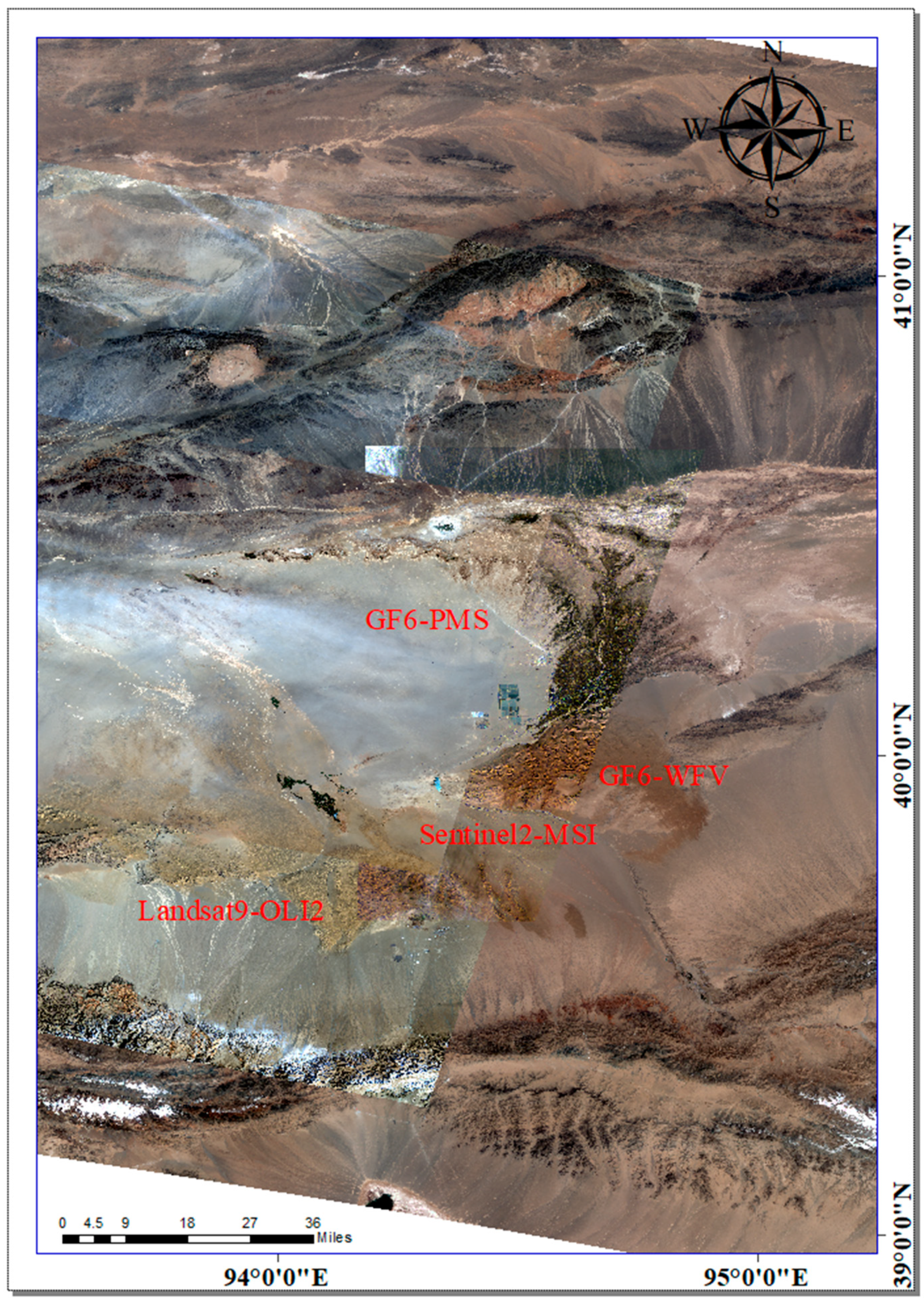
2.1. Test Sites
2.2. Satellites
2.3. Data Set
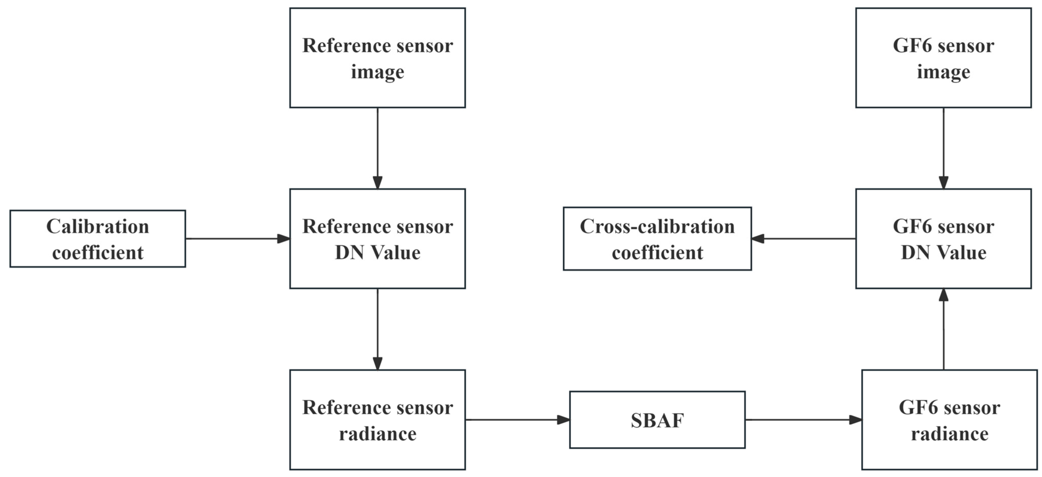
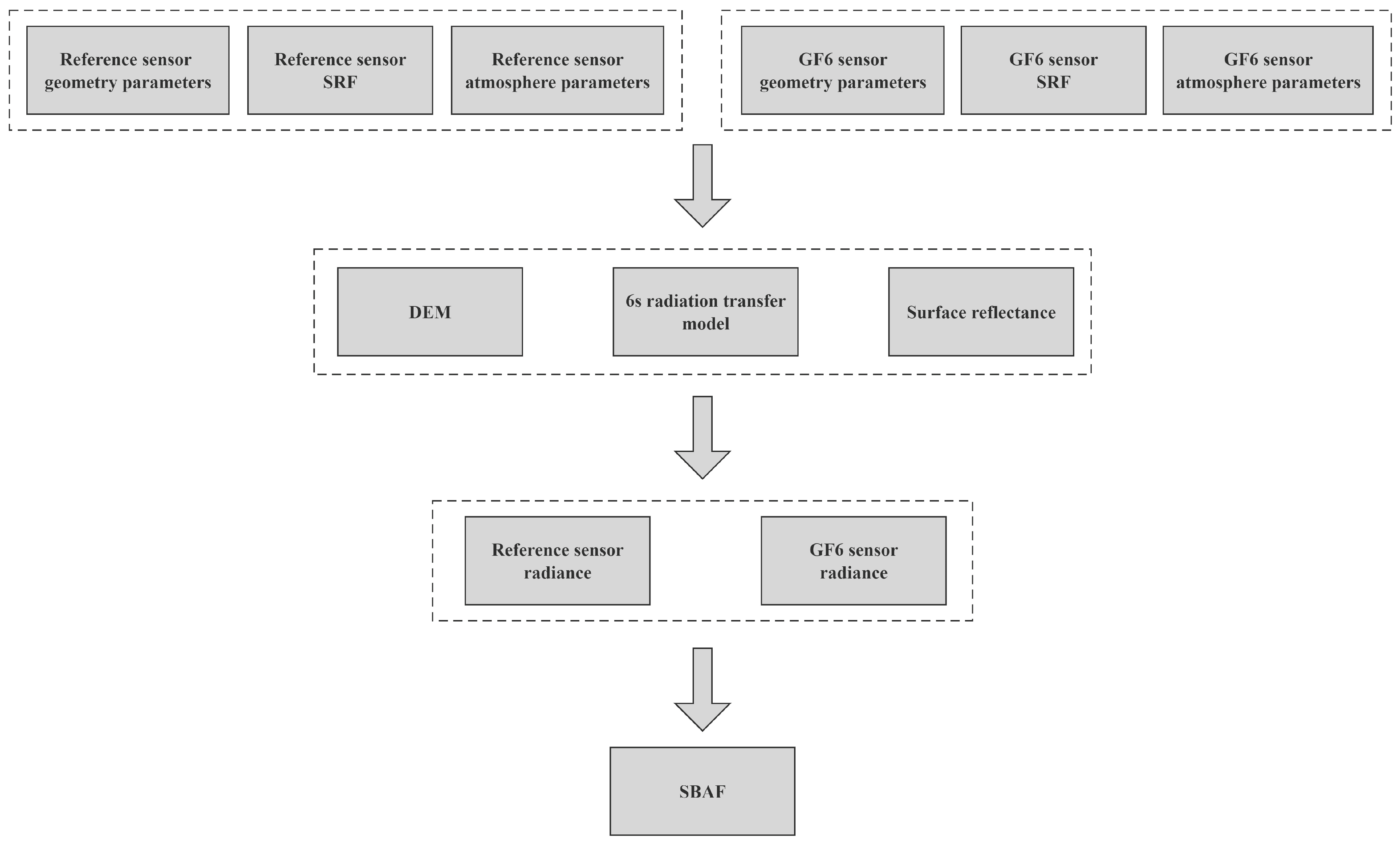
3. Methodology
4. Results
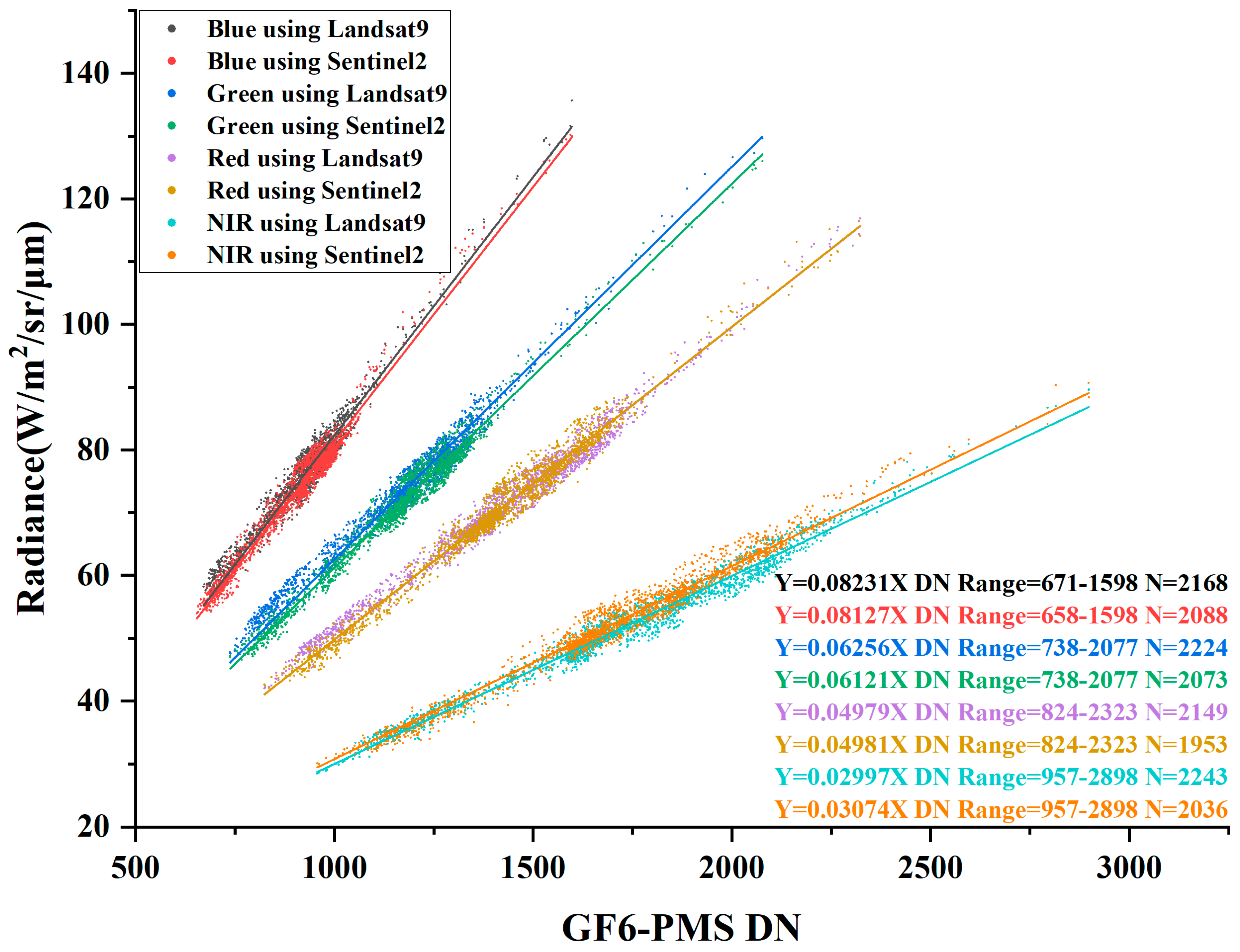
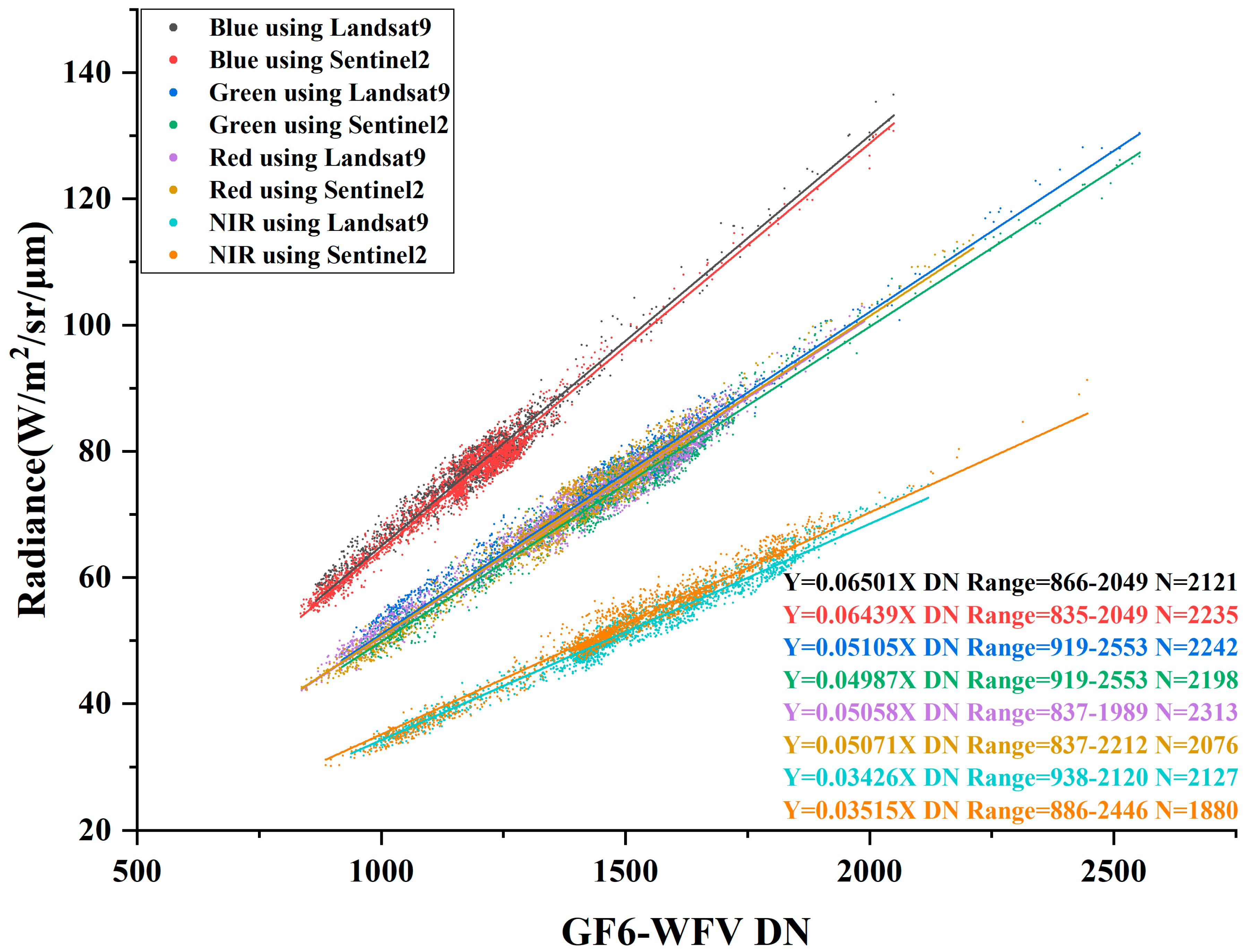
4.1. Comparison of Radiance between Different Reference Sensors
4.2. Calibration Result Using Difference Reference Sensors
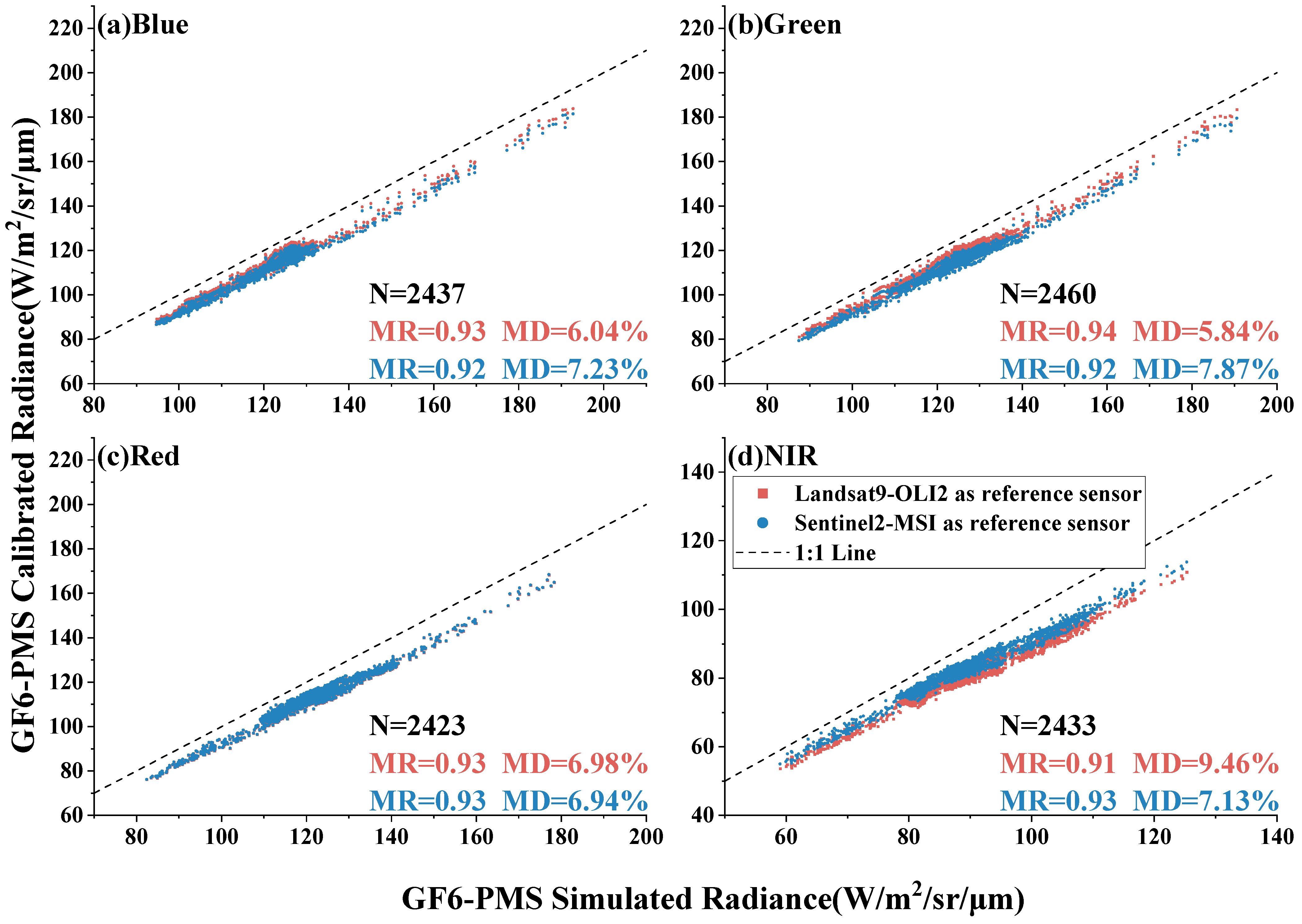
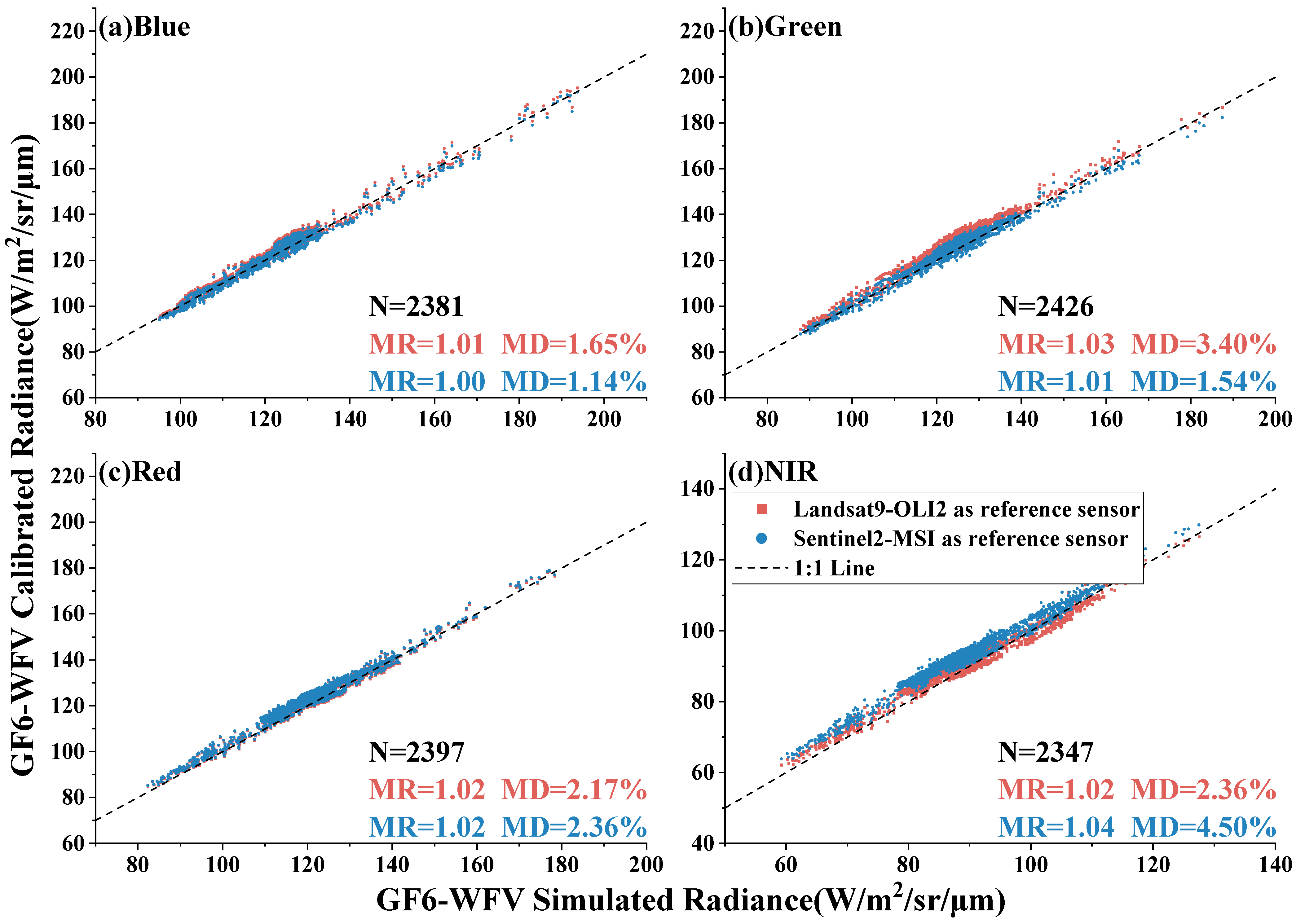
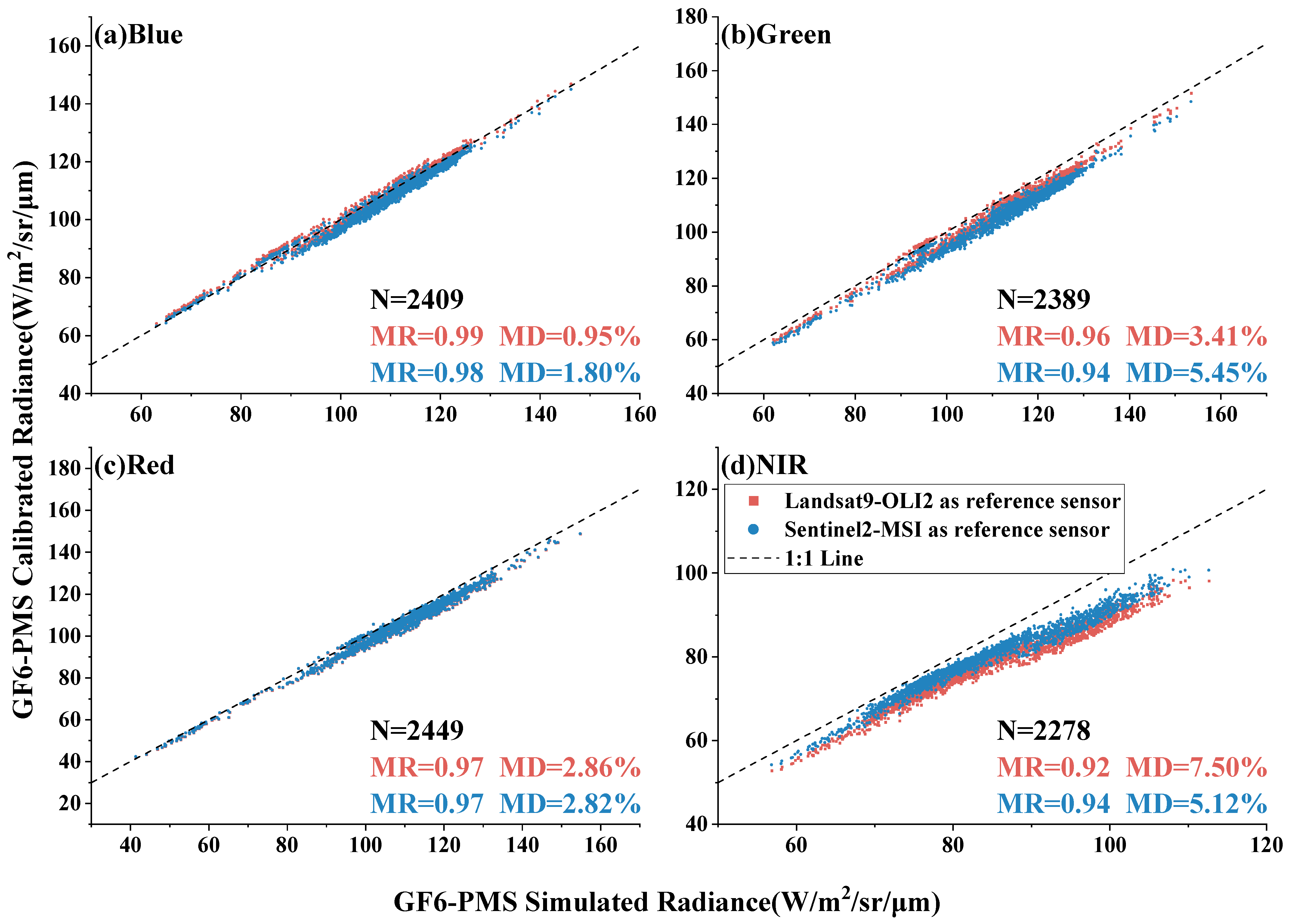
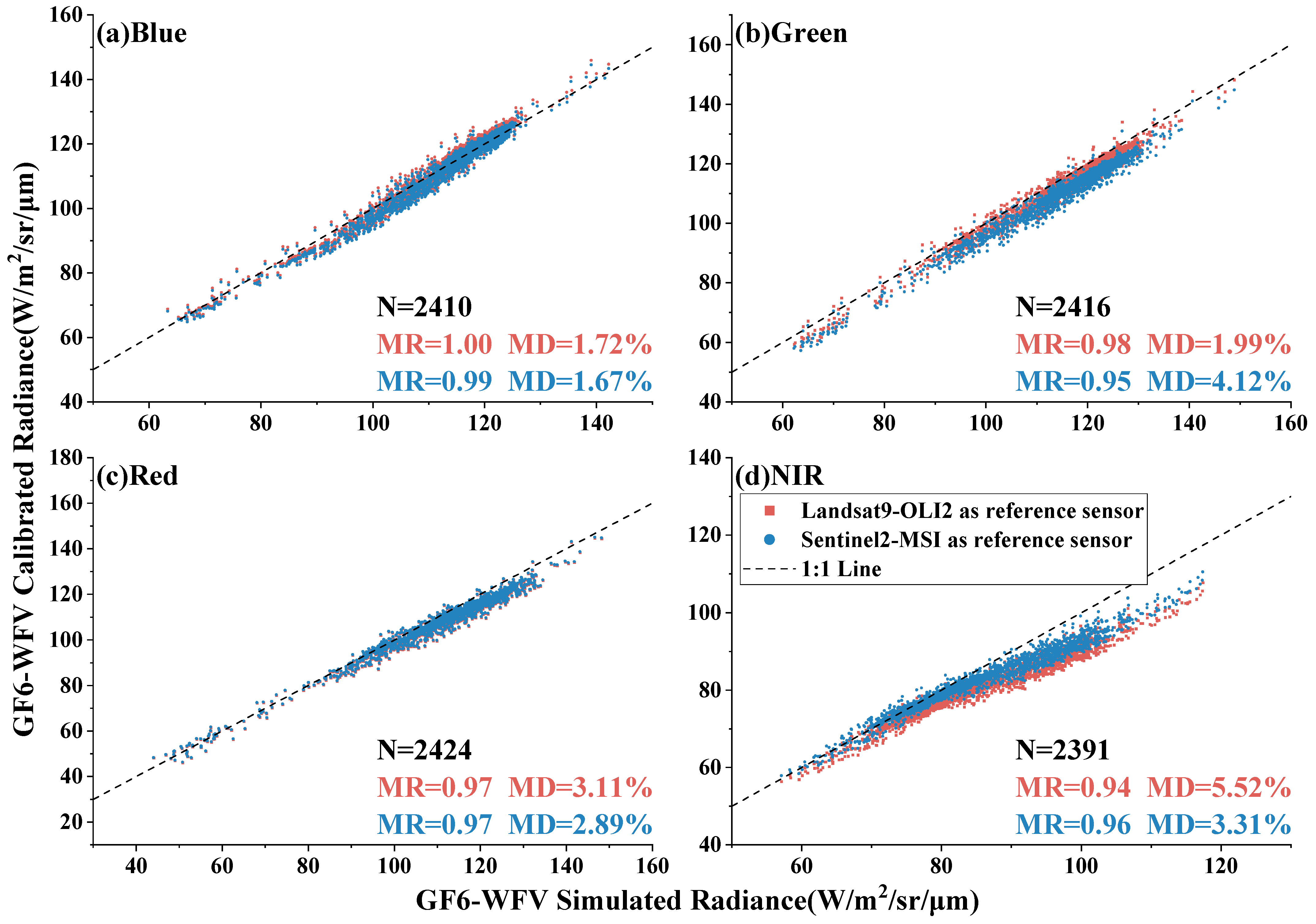
4.3. Verification of Calibration Results
5. Discussion
5.1. Cross-Calibration Results without SBAF Correction
5.2. Comparison of Results from Different Cross-Calibration Methods
5.3. Ground Synchronous Observation Verification and Evaluation
6. Conclusions
Author Contributions
Funding
Data Availability Statement
Conflicts of Interest
References
- Dinguirard, M.; Slater, P.N. Calibration of Space-Multispectral Imaging Sensors: A Review. Remote Sens. Environ. 1999, 68, 194–205. [Google Scholar] [CrossRef]
- Thome, K.J. Absolute radiometric calibration of Landsat 7 ETM+ using the reflectance-based method. Remote Sens. Environ. 2001, 78, 27–38. [Google Scholar] [CrossRef]
- Barsi, J.A.; Markham, B.L.; Helder, D.L.; Chanderd, G. Radiometric calibration status of Landsat-7 and Landsat-5. In Proceedings of the Sensors, Systems, and Next-Generation Satellites XI, Florence, Italy, 17–20 September 2007. [Google Scholar]
- Six, D.; Fily, M.; Alvain, S.; Henry, P.; Benoist, J.-P. Surface characterisation of the Dome Concordia area (Antarctica) as a potential satellite calibration site, using Spot 4/Vegetation instrument. Remote Sens. Environ. 2004, 89, 83–94. [Google Scholar] [CrossRef]
- Vermote, E.F.; Saleous, N.Z. Calibration of NOAA16 AVHRR over a desert site using MODIS data. Remote Sens. Environ. 2006, 105, 214–220. [Google Scholar] [CrossRef]
- Cao, C.; Luccia, F.J.D.; Xiong, X.; Wolfe, R.; Weng, F. Early On-Orbit Performance of the Visible Infrared Imaging Radiometer Suite Onboard the Suomi National Polar-Orbiting Partnership (S-NPP) Satellite. IEEE Trans. Geosci. Remote Sens. 2014, 52, 1142–1156. [Google Scholar] [CrossRef]
- Sun, J.Q.; Xiong, X.; Barnes, W.L.; Guenther, B. MODIS Reflective Solar Bands On-Orbit Lunar Calibration. IEEE Trans. Geosci. Remote Sens. 2007, 45, 2383–2393. [Google Scholar] [CrossRef]
- Markham, B.L.; Thome, K.J.; Barsi, J.A.; Kaita, E.; Helder, D.L.; Barker, J.L.; Scaramuzza, P.L. Landsat-7 ETM+ on-orbit reflective-band radiometric stability and absolute calibration. IEEE Trans. Geosci. Remote Sens. 2004, 42, 2810–2820. [Google Scholar] [CrossRef]
- Chen, L.; Zhang, P.; Lv, J.; Xu, N.; Hu, X. Radiometric calibration evaluation for RSBs of Suomi-NPP/VIIRS and Aqua/MODIS based on the 2015 Dunhuang Chinese Radiometric Calibration Site in situ measurements. Int. J. Remote Sens. 2017, 38, 5640–5656. [Google Scholar] [CrossRef]
- Biggar, S.F.; Slater, P.N.; Gellman, D.I. Uncertainties in the in-flight calibration of sensors with reference to measured ground sites in the 0.4–1.1 μm range. Remote Sens. Environ. 1994, 48, 245–252. [Google Scholar] [CrossRef]
- Slater, P.N.; Biggar, S.F.; Holm, R.G.; Jackson, R.D.; Mao, Y.; Moran, M.S.; Palmer, J.M.; Yuan, B. Reflectance- and radiance-based methods for the in-flight absolute calibration of multispectral sensors. Remote Sens. Environ. 1987, 22, 11–37. [Google Scholar] [CrossRef]
- Biggar, S.; Dinguirard, M.; Gellman, D.; Henry, P.; Jackson, R.; Moran, M.; Slater, P. Radiometric calibration of SPOT 2 HRV—A comparison of three methods. In Proceedings of the SPIE-International Society for Optical Engineering, Orlando, FL, USA, 3–5 April 1991. [Google Scholar]
- Sterckx, S.; Wolters, E. Radiometric Top-of-Atmosphere Reflectance Consistency Assessment for Landsat 8/OLI, Sentinel-2/MSI, PROBA-V, and DEIMOS-1 over Libya-4 and RadCalNet Calibration Sites. Remote Sens. 2019, 11, 2253. [Google Scholar] [CrossRef]
- Gao, H.; Gu, X.; Yu, T.; Sun, Y.; Liu, Q. Cross-Calibration of GF-1 PMS Sensor With Landsat 8 OLI and Terra MODIS. IEEE Trans. Geosci. Remote Sens. 2016, 54, 4847–4854. [Google Scholar] [CrossRef]
- Voskanian, N.; Thome, K.; Wenny, B.N.; Tahersima, M.H.; Yarahmadi, M. Combining RadCalNet Sites for Radiometric Cross Calibration of Landsat 9 and Landsat 8 Operational Land Imagers (OLIs). Remote Sens. 2023, 15, 5752. [Google Scholar] [CrossRef]
- Tang, H.; Xie, J.; Tang, X.; Li, Q. Radiometric Cross-calibration of ZY3 Satellite with GF1 PMS/WFV and Landsat-8 OLI. In Proceedings of the IGARSS 2019—2019 IEEE International Geoscience and Remote Sensing Symposium, Yokohama, Japan, 28 July–2 August 2019. [Google Scholar]
- Han, J.; Tao, Z.; Xie, Y.; Liu, Q.; Huang, Y. Radiometric Cross-Calibration of GF-4/PMS Based on Radiometric Block Adjustment. IEEE Trans. Geosci. Remote Sens. 2021, 59, 4522–4534. [Google Scholar] [CrossRef]
- Shin, D.Y.; Ahn, H.Y.; Lee, S.G.; Choi, C.U.; Kim, J.S. Radiometric Cross-calibration of KOMPSAT-3A with Landsat-8. In Proceedings of the 23rd Congress of the International-Society-for-Photogrammetry-and-Remote-Sensing (ISPRS), Prague, Czech Republic, 12–19 July 2016. [Google Scholar]
- Han, J.; Tao, Z.; Xie, Y.; Li, H.; Liu, Q.; Guan, X. A Novel Radiometric Cross-Calibration of GF-6/WFV With MODIS at the Dunhuang Radiometric Calibration Site. IEEE J. Sel. Top. Appl. Earth Obs. Remote Sens. 2021, 14, 1645–1653. [Google Scholar] [CrossRef]
- Li, X.; Guo, Z.F.; Gao, L.R. Cross-calibration of EO-1 MODIS to SZ-3 CMODIS using Dunhuang test site. In Proceedings of the IGARSS 2005: IEEE International Geoscience And Remote Sensing Symposium, Seoul, Republic of Korea, 25–29 July 2005. [Google Scholar]
- Yang, A.; Zhong, B.; Hu, L.; Wu, S.; Xu, Z.; Wu, H.; Wu, J.; Gong, X.; Wang, H.; Liu, Q. Radiometric Cross-Calibration of the Wide Field View Camera Onboard GaoFen-6 in Multispectral Bands. Remote Sens. 2020, 12, 1037. [Google Scholar] [CrossRef]
- Goward, S.N.; Williams, D.L.; Arvidson, T.; Rocchio, L.E.P.; Irons, J.R.; Russell, C.A.; Johnston, S.S. Landsat’s Enduring Legacy: Pioneering Global Land Observations from Space. Photogramm. Eng. Remote Sens. 2022, 88, 357–358. [Google Scholar] [CrossRef]
- Pla, M.; Bota, G.; Duane, A.; Balagué, J.; Curcó, A.; Gutiérrez, R.; Brotons, L. Calibrating Sentinel-2 Imagery with Multispectral UAV Derived Information to Quantify Damages in Mediterranean Rice Crops Caused by Western Swamphen (Porphyrio porphyrio). Drones 2019, 3, 45. [Google Scholar] [CrossRef]
- Spoto, F.; Sy, O.; Laberinti, P.; Martimort, P.; Fernandez, V.; Colin, O.; Hoersch, B.; Meygret, A. Overview of Sentinel-2. In Proceedings of the 2012 IEEE International Geoscience and Remote Sensing Symposium (IGARSS), Munich, Germany, 22–27 July 2012. [Google Scholar]
- Wang, Y.; Liu, Y.; Zhao, W.; Zeng, J.; Wang, H.; Wang, R.; Xu, Z.; Han, Q. Time-Series Cross-Radiometric Calibration and Validation of GF-6/WFV Using Multi-Site. Remote Sens. 2024, 16, 1287. [Google Scholar] [CrossRef]
- Li, X.; Gu, X.; Min, X.; Yu, T.; Fu, Q.; Zhang, Y.; Li, X. Radiometric cross-calibration of the CBERS-02 CCD camera with the TERRA MODIS. Sci. China Ser. E Technol. Sci. 2005, 48, 44–60. [Google Scholar] [CrossRef]
- Chander, G.; Markham, B.L.; Helder, D.L. Summary of current radiometric calibration coefficients for Landsat MSS, TM, ETM+, and EO-1 ALI sensors. Remote Sens. Environ. 2009, 113, 893–903. [Google Scholar] [CrossRef]
- Kotchenova, S.Y.; Vermote, E.F. Validation of a vector version of the 6S radiative transfer code for atmospheric correction of satellite data. Part II. Homogeneous Lambertian and anisotropic surfaces. Appl. Opt. 2007, 46, 4455–4464. [Google Scholar] [CrossRef] [PubMed]


| Sensor | PMS | WFV | OLI2 | MSI |
|---|---|---|---|---|
| Time (UTC) | 05:01 | 05:01 | 04:26 | 04:28 |
| Solar Zenith (°) | 54.35 | 54.34 | 56.78 | 55.81 |
| Solar Azimuth (°) | 163.90 | 163.71 | 153.47 | 156.99 |
| Sensor Zenith (°) | 6.03 | 6.32 | 7.05 | 4.31 |
| Sensor Azimuth (°) | 14.08 | 24.99 | 286.86 | 106.28 |
| AOD (550 nm) | 0.056 | |||
| Sensor | Band | Reference Sensor | |
|---|---|---|---|
| Landsat9 | Sentinel2 | ||
| GF6-PMS | Blue | 1.0553 | 1.0167 |
| Green | 1.0612 | 1.0133 | |
| Red | 1.0452 | 1.0235 | |
| NIR | 1.1162 | 1.0510 | |
| GF6-WFV | Blue | 1.0613 | 1.0225 |
| Green | 1.0672 | 1.0190 | |
| Red | 1.0460 | 1.0243 | |
| NIR | 1.1233 | 1.0577 | |
| Sensor | Band | Reference Sensor | Official Gain | Gain Difference | |||
|---|---|---|---|---|---|---|---|
| Landsat9-OLI2 | Sentinel2-MSI | Da | Db | Dc | |||
| GF6-PMS | Blue | 0.08231 | 0.08127 | 0.0821 | 1.26% | 0.26% | 1.01% |
| Green | 0.06256 | 0.06121 | 0.0671 | 2.16% | 6.77% | 8.78% | |
| Red | 0.04979 | 0.04981 | 0.0518 | 0.04% | 3.88% | 3.84% | |
| NIR | 0.02997 | 0.03074 | 0.031 | 2.57% | 3.32% | 0.84% | |
| GF6-WFV | Blue | 0.06501 | 0.06439 | 0.0633 | 0.95% | 2.70% | 1.72% |
| Green | 0.05105 | 0.04987 | 0.0532 | 2.31% | 4.04% | 6.26% | |
| Red | 0.05058 | 0.05071 | 0.0508 | 0.26% | 0.43% | 0.18% | |
| NIR | 0.03426 | 0.03515 | 0.0325 | 2.60% | 5.42% | 8.15% | |
| Sensor | PMS | WFV | MSI | PMS | WFV | OLI2 |
|---|---|---|---|---|---|---|
| Time (UTC) | 05:03 | 05:03 | 04:27 | 04:55 | 04:55 | 04:19 |
| Solar Zenith (°) | 19.21 | 19.23 | 21.66 | 22.82 | 22.85 | 27.28 |
| Solar Azimuth (°) | 150.77 | 150.31 | 137.61 | 145.95 | 145.56 | 130.64 |
| Sensor Zenith (°) | 6.05 | 6.34 | 4.23 | 7.95 | 7.33 | 4.63 |
| Sensor Azimuth (°) | 13.89 | 24.78 | 108.95 | 329.53 | 337.19 | 112.89 |
| AOD (550 nm) | 0.223 | 0.145 | ||||
| Sensor | Band | Reference Sensor | Official Gain | Gain Difference | |||
|---|---|---|---|---|---|---|---|
| Landsat9-OLI2 | Sentinel2-MSI | Da | Db | Dc | |||
| GF6-PMS | Blue | 0.0782 | 0.0804 | 0.0821 | 2.81% | 4.75% | 2.07% |
| Green | 0.059 | 0.0608 | 0.0671 | 3.05% | 12.07% | 9.39% | |
| Red | 0.0477 | 0.0492 | 0.0518 | 3.14% | 7.92% | 5.02% | |
| NIR | 0.0269 | 0.0296 | 0.031 | 10.04% | 13.23% | 4.52% | |
| GF6-WFV | Blue | 0.0614 | 0.0632 | 0.0633 | 2.93% | 3.00% | 0.16% |
| Green | 0.0478 | 0.0493 | 0.0532 | 3.14% | 10.15% | 7.33% | |
| Red | 0.0485 | 0.0501 | 0.0508 | 3.30% | 4.53% | 1.38% | |
| NIR | 0.0307 | 0.0337 | 0.0325 | 9.77% | 5.54% | 3.69% | |
| Sensor | SBAF TYPE | Landsat9 as Reference Sensor | Sentinel2 as Reference Sensor | ||||||
|---|---|---|---|---|---|---|---|---|---|
| Band | Band | ||||||||
| Blue | Green | Red | NIR | Blue | Green | Red | NIR | ||
| GF6-PMS | SBAFRef | 0.08283 | 0.06242 | 0.04979 | 0.03024 | 0.08038 | 0.06311 | 0.05134 | 0.03122 |
| SBAFRad | 0.08231 | 0.06256 | 0.04979 | 0.02997 | 0.08127 | 0.06121 | 0.04981 | 0.03074 | |
| (SBAFRef − SBAFRad)/SBAFRad × 100% | 0.63 | −0.22 | 0.00 | 0.90 | −1.10 | 3.10 | 3.07 | 1.56 | |
| GF6-WFV | SBAFRef | 0.06555 | 0.05078 | 0.05078 | 0.03459 | 0.06362 | 0.05134 | 0.05237 | 0.03572 |
| SBAFRad | 0.06501 | 0.05105 | 0.05058 | 0.03426 | 0.06439 | 0.04987 | 0.05071 | 0.03515 | |
| (SBAFRef − SBAFRad)/SBAFRad × 100% | 0.83 | −0.53 | 0.40 | 0.96 | −1.20 | 2.95 | 3.27 | 1.62 | |
| Sensor | PMS | WFV |
|---|---|---|
| Time (UTC) | 04:59 | 04:59 |
| Solar Zenith (°) | 61.37 | 61.35 |
| Solar Azimuth (°) | 171.87 | 171.70 |
| Sensor Zenith (°) | 6.02 | 6.32 |
| Sensor Azimuth (°) | 14.03 | 24.94 |
| AOD (550 nm) | 0.16 | |
| Sensor | Band | 6S Simulated Radiance (W/m2/sr/μm) | Cross-Calibration Coefficient Radiance of Different Reference Sensors (W/m2/sr/μm) | |
|---|---|---|---|---|
| Landsat9 | Sentinel2 | |||
| PMS | Blue | 63.23 | 66.92 | 66.07 |
| Relative Difference | 5.83% | 4.50% | ||
| Green | 59.82 | 61.12 | 59.80 | |
| Relative Difference | 2.17% | 0.03% | ||
| Red | 55.48 | 56.36 | 56.38 | |
| Relative Difference | 1.58% | 1.63% | ||
| NIR | 39.88 | 38.51 | 39.50 | |
| Relative Difference | 3.43% | 0.95% | ||
| WFV | Blue | 63.54 | 66.83 | 66.19 |
| Relative Difference | 5.18% | 4.18% | ||
| Green | 59.64 | 63.40 | 61.94 | |
| Relative Difference | 6.31% | 3.86% | ||
| Red | 55.17 | 60.59 | 60.75 | |
| Relative Difference | 9.82% | 10.11% | ||
| NIR | 41.46 | 43.30 | 44.43 | |
| Relative Difference | 4.45% | 7.16% | ||
Disclaimer/Publisher’s Note: The statements, opinions and data contained in all publications are solely those of the individual author(s) and contributor(s) and not of MDPI and/or the editor(s). MDPI and/or the editor(s) disclaim responsibility for any injury to people or property resulting from any ideas, methods, instructions or products referred to in the content. |
© 2024 by the authors. Licensee MDPI, Basel, Switzerland. This article is an open access article distributed under the terms and conditions of the Creative Commons Attribution (CC BY) license (https://creativecommons.org/licenses/by/4.0/).
Share and Cite
Wang, H.; He, Z.; Wang, S.; Zhang, Y.; Tang, H. Radiometric Cross-Calibration of GF6-PMS and WFV Sensors with Sentinel 2-MSI and Landsat 9-OLI2. Remote Sens. 2024, 16, 1949. https://doi.org/10.3390/rs16111949
Wang H, He Z, Wang S, Zhang Y, Tang H. Radiometric Cross-Calibration of GF6-PMS and WFV Sensors with Sentinel 2-MSI and Landsat 9-OLI2. Remote Sensing. 2024; 16(11):1949. https://doi.org/10.3390/rs16111949
Chicago/Turabian StyleWang, Hengyang, Zhaoning He, Shuang Wang, Yachao Zhang, and Hongzhao Tang. 2024. "Radiometric Cross-Calibration of GF6-PMS and WFV Sensors with Sentinel 2-MSI and Landsat 9-OLI2" Remote Sensing 16, no. 11: 1949. https://doi.org/10.3390/rs16111949
APA StyleWang, H., He, Z., Wang, S., Zhang, Y., & Tang, H. (2024). Radiometric Cross-Calibration of GF6-PMS and WFV Sensors with Sentinel 2-MSI and Landsat 9-OLI2. Remote Sensing, 16(11), 1949. https://doi.org/10.3390/rs16111949