Article

A Comprehensive Signal Quality Assessment for BDS/Galileo/GPS Satellites and Signals

1
Beijing Satellite Navigation Center, Beijing 100094, China
2
Institute of Geospatial Information, Information Engineering University, Zhengzhou 450001, China
*
Author to whom correspondence should be addressed.
Remote Sens. 2024, 16(13), 2277; https://doi.org/10.3390/rs16132277
Submission received: 11 May 2024 / Revised: 11 June 2024 / Accepted: 18 June 2024 / Published: 21 June 2024

Abstract

:
With the modernization of global navigation satellite systems (GNSS), especially the rapid development of the BeiDou Navigation Satellite System (BDS), more observations of satellites and signals have become available. Using data of the globally distributed MGEX stations, a systematic and comprehensive evaluation of signal characteristics for BDS-3, BDS-2, GPS, and Galileo is conducted in terms of carrier-to-noise ratio (C/N0), code noise, and multipath in the contribution. First, a comprehensive signal quality assessment method for BDS/Galileo/GPS satellites and signals is proposed, including C/N0 modeling and MP modeling. For BDS, the BDS-3 satellites apparently have higher signal power than the BDS-2 satellites at the same frequency such as B1I and B3I, and the signal B2a of BDS-3 is superior to other signals in regard to signal power, which is comparable with the superior Galileo E5 signals and GPS L5. Among all the signals, the observation accuracy of E5 is the highest regardless of receiver types, and next highest are BDS-3 B2a and GPS L5. Due to not being affected by the systematic code errors of BDS-2, the observations of BDS-3 satellites contain smaller multipath errors than that of BDS-2 satellites. As for the multipath suppression performance, the BDS-3 signal B2a, GPS L5, and Galileo E5 and E5b perform better than the other signals, which may be related to their wide signal bandwidths.

1. Introduction

As of May 2024, the data of 30 BDS-3 satellites in orbit are available, including 3 GEO satellites, 3 IGSO satellites, and 24 MEO satellites [1,2,3,4], and currently, BDS constellation is composed of BDS-2 and BDS-3 [5,6]. Furthermore, four BDS-3 experimental satellites (BDS-3s) are available, including two IGSO and two MEO satellites [7,8]. BDS-3 added two new signals, B1C and B2a, on the basis of compatibility with BDS-2 B1I and B3I signals [9,10,11,12,13]. Table 1 shows the characteristics of the current BDS-3 public signals. Apparently, the two new signals, B1C and B2a, have higher ranging accuracy, wider bandwidth, and better interoperability. In the signal design, to provide better compatibility and interoperability, the B1C frequency is selected as 1575.42MHz, which is used for frequency multiplexing with Galileo E1 and GPS L1, and B2a is selected as 1176.45 MHz, which is compatible with Galileo E5a and GPS L5.
With the continuous improvement of the GNSS navigation and positioning theory, the research on signal quality evaluation of GPS, Galileo, BDS-2, and other systems has been relatively mature. The contents of the signal quality evaluation include the observed signal-to-noise ratio [14,15,16], pseudorange multipath and noise [17,18,19,20], and pseudorange and carrier observation accuracy [21,22,23]. For the new signal E5 of the Galileo, the research of Zaminpardaz et al. on the four IOV and nine FOC satellites showed that the E5 signal modulated with AltBOC has significantly better signal power and lower noise and multipath biases among the five Galileo signals. The instantaneous ambiguity fixation on the E5 signal can be achieved by correcting the multipath [19]. Similarly, the research by Tian et al. and Simsky et al. indicated that apart from outperforming others in signal powers, the E5 signal has a high level of short delay multipath suppression, which may be related to its advanced signal modulation method [22,23]. As for BDS, the characteristics of the signals B1C, B2a, and B2b were first analyzed by Zhang et al., utilizing the five BDS-3 satellites, and it was found that the elevation-dependent pseudorange biases that appeared in the BDS-2 satellite observations no longer exist in the new-generation BDS-3 satellites [24].
The availability of more BDS-3 satellite observation data has made the evaluation of BDS-3 performance a research hotspot. Fu Zheng et al. studied the receiver pseudorange deviation between BDS-2 and BDS-3 and found that the receiver pseudorange deviation between BDS-3 and BDS-2 varies greatly and is related to the receiver type [25]. By investigating the intrinsic characteristics of receiver-related biases in the combination of BDS-3 and BDS-2, Mi et al. concluded that there exist noticeable differences in the epoch-wise DCB estimates of the same type between BDS-3 and BDS-2 [26]. As for the atomic clock, the drift rate and frequency stability of the clock on the BDS-3 satellite are significantly better than those on BDS-2 [27,28]. Furthermore, when studying the combination positioning of BDS-3 and other systems, the increase in BDS-3 new signals can significantly improve the positioning performance of BDS/GPS/Galileo [29,30]. However, it was found that the inter-system bias (ISB) between BDS-3 and other GNSS systems cannot be ignored. Even ISB exists between BDS-3 and BDS-2 [31,32].
The excellent characteristics of BDS-3 interest us in further evaluating its performance compared to other GNSS systems. In addition, with the completion of BDS-3, the multi-system fusion positioning service with BDS as the core has preliminary conditions. The combination of BDS-3 with other GNSS systems can provide sufficient observations and huge potential for improving the accuracy, reliability, and availability of PNT services [33,34,35], yet the differences in data quality and random characteristics between observations of different types of satellites and signals make it impossible to achieve ideal results in multi-system fusion positioning. In addition, there are currently many brands of receivers for BDS-3 data processing, which also makes the quality and characteristics of the observation data inconsistent. Therefore, conducting a comprehensive evaluation of BDS-3 is of great significance, as compared to other GNSS systems.
Utilizing data from globally distributed MGEX stations that can receive BDS-3 satellite signals, this paper first provides a brief description of the BDS-3 signal regime, then provides a systematic and comprehensive assessment of its data quality, analyzing and comparing it with other GNSS systems.

2. Data and Methods

In order to study the performances of signals and satellites of BDS-3, quality evaluations on C/N0, code noise, and multipath were conducted using data from the MGEX stations that can process the BDS-3 signals.

2.1. Data

Table 2 shows the classification of the MGEX stations that can process BDS-3 signals from 14 May to 20 May 2019 (DOYs 2019, 134–140). The earlier use of data here is because BDS-3 data are just available at this time, and BDS-2 data are also relatively complete, laying a solid foundation for the subsequent BDS performance analysis. In the experiment, as the stations equipped with the same type of receiver showed high consistency, the observations of the representative stations were used for experimental analysis to compare the characteristics of C/N0, code noise, and the multipath between BDS-3 and the other GNSS systems in different types of receivers. All the selected stations were installed in an open sky environment, and data can be found at the IGS official website (http://www.igs.org/mgex/data-products/#data, accessed on 2 April 2024).

2.2. Carrier-to-Noise Density Ratio Evaluation Model

The carrier-to-noise density ratio (C/N0) values are usually used to indicate the signal quality of GNSS observed data. In the experiment, the C/N0 values of all epochs corresponding to a certain satellite s at the frequency j were first extracted, and then the corresponding satellite elevation E L on each epoch was calculated.
E L = a r c s i n   ( e u )
where e u is the transformation coordinate value between the earth-centered fixed coordinate system and the topocentric coordinate system.
Two models with regard to C / N 0 were established in the contribution so as to evaluate the power of different signals in different GNSS systems.
The first model was for comparing the signal power between different satellite types at the same frequency. In the model, the satellite elevations were used as the basis for grouping the C / N 0 values, and the C / N 0 values of a certain satellite at a certain frequency point were divided into groups every 10 degrees. Afterward, an average value of C / N 0 was calculated within each group. The formula is as follows.
C / N 0 j , a v e s ( k ) = i = 1 n C / N 0 j s ( i ) [ k 1 0 , ( k + 1 ) 1 0 ] n        
where k = 0 ~ 8 denotes the k t h elevation group, and n is the number of epochs within the elevation group of [ k · 10 ° ,   ( k + 1 ) · 10 ° ] . C / N 0 j , a v e s ( k ) is the average C / N 0 value of satellite s at the frequency j within the k t h elevation interval.
The second model was for comparing the signal power at different signals. Different from the first model, the C / N 0 values over the same type of satellites at the same frequency were grouped according to their elevations. Then, C / N 0 values in each elevation interval of 10 degrees were averaged, and STDs of C / N 0 were calculated to estimate uncertainties.
C / N 0 j , a v e ( k ) = s = 1 m i = 1 n C / N 0 j s ( i ) [ k 1 0 , ( k + 1 ) 1 0 ] n
where m is the number of satellites that are the same type, and C / N 0 j , a v e s ( k ) is the average C / N 0 value over a certain type of satellite at the frequency j within the k t h elevation interval. STDs can be expressed as:
C / N 0 j , STD ( k ) = s = 1 m i = 1 n ( C / N 0 j s ( i ) [ k 1 0 , ( k + 1 ) 1 0 ] C / N 0 j , a v e ( k ) ) 2 n

2.3. Noise Assessment Model

The BDS, GPS, or Galileo single-system pseudorange and phase-nondifference observation equations are:
P r , j s = ρ r s + ( d t r d t s ) + T r s + β j I r , j s + ( d r , j + d , j s ) + e r , j s
Φ r , j s = ρ r s + ( d t r d t s ) + T r s β j I r , j s + ε r , j s + λ j ( N r , j s + b r , j + b , j s )
P r , j s Φ r , j s = 2 β j I r s + ( d r , j + d , j s ) λ j ( N r , j s + b r , j + b , j s )
Δ ( P r , j s Φ r , j s ) = Δ e r , j s
where P r , j s is the pseudorange observation, and Φ r , j s is the carrier phase observation. ρ r s is the geometry term, and d t r and d t s are the receiver clock error and satellite clock error. T r s is the tropospheric delay, and I r , j s is the ionospheric delay. d r , j and d , j s are the hardware delays of the receiver and satellite in pseudorange observations, respectively. b r , j and b , j s represent the initial phase deviation and hardware delay of the receiver and satellite in the carrier phase observation. N r , j s is the ambiguity term in the carrier phase observation. e r , j s and ε r , j s represent other unmodeled errors, such as observation noise and multipath effects in pseudorange and carrier phase observations, respectively.
Using the pseudorange minus the carrier, the geometric term can be eliminated, and then using the inter-epoch difference, the ambiguity and ionospheric term can be eliminated without circle slips. Apart from this, the phase noise was small and negligible in comparison to the pseudorange noise; thus, the code noise can be evaluated by the above equation.

2.4. Code Multipath Analysis

A GNSS receiver theoretically receives a direct wave signal from the GNSS satellite, but in reality, in addition to the direct wave, there are several indirect waves that reach the receiver’s signal-receiving antenna, including reflected waves from ground or ground objects, reflected waves from the satellite, and scattered waves from the atmospheric propagation medium.
Generally, the code multipath can be evaluated by constructing a combination of multipaths using the pseudorange and carrier phase observations, which is expressed as follows.
M P j s = P r , j s f j 2 + f i 2 f j 2 f i 2 Φ r , j s + 2 f i 2 f j 2 f i 2 Φ r , i s = P r , j s ( f j 2 f j 2 f i 2 Φ r , j s f i 2 f j 2 f i 2 Φ r , j s ) f i 2 f j 2 f i 2 ( Φ r , j s Φ r , i s )
The penultimate term of the multipath combination corresponds to the ionosphere-free combination of the carrier phase so as to eliminate the effect of the first-order ionospheric delay, while the last term is the geometry-free combination so that the effect of the geometry term in the combination can be effectively eliminated.
Substituting the observed value equation into the above equation gives the equation:
M P j s = d M j f i 2 + f j 2 f j 2 f i 2 d m j + 2 f i 2 f j 2 f i 2 d m i B
where the subscripts i and j   ( i j ) denote the frequency, and d M and d m stand for the code multipath error and the carrier phase multipath error. B includes the ambiguity term, as well as the hardware delay deviation, which can be expressed as
B = f i 2 + f j 2 f j 2 f i 2 λ j N j 2 f i 2 f j 2 f i 2 λ i N i d j d s
Theoretically, the carrier phase multipath error and the systematic errors, such as phase noise, were small, making them negligible with respect to the code multipath. When the carrier phase observation does not appear in the cycle slip, the ambiguity parameter can be treated as a constant. The differential code deviation was also stable in the short term. Therefore, in the multipath combination, it was possible to smooth the irrelevant items by taking the average value. Then, the code multipath in a complete arc can be obtained as
M P j , v a r s = M P j s < M P j s >
where the operator < · > indicates smoothing in the time domain.
In addition, considering the fact that the code accuracy of some special signals can reach the centimeter level, it was necessary to try to make the frequency difference between the two signals as large as possible to minimize the effects of phase multipath and phase noise when choosing to build the multipath combination. Therefore, the frequency f j and f i were chosen in the paper, as shown in Table 3.
Similar to the C/N0 model, the multipath values on all epochs corresponding to each satellite at the same frequency were grouped according to the satellite elevations, with each 10° elevation as a split. Then, the multipath values within the same elevation interval were averaged.
M P j , a v e s ( k ) = i = 1 n M P j , v a r s ( i ) ) [ k 1 0 , ( k + 1 ) 1 0 ] n
where M P j , a v e s ( k ) denotes the mean multipath value of satellite s at frequency j in the k t h set of elevation intervals.

3. Experiment Results

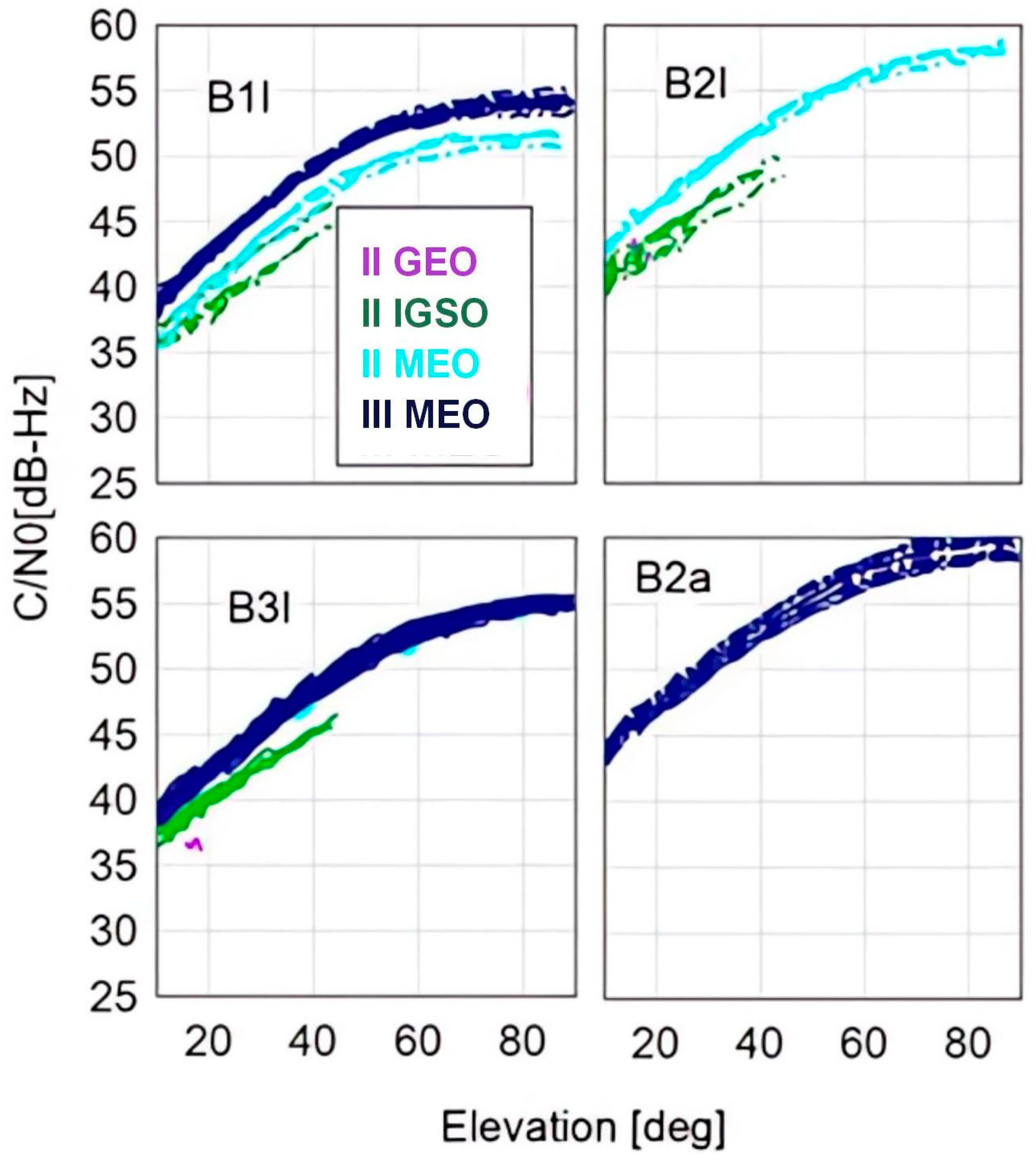
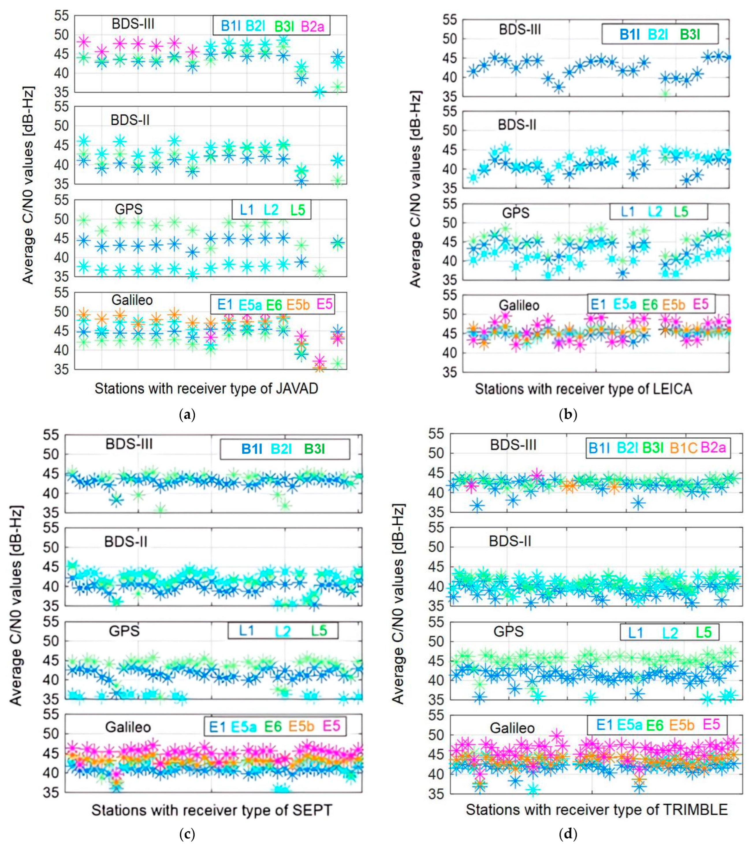
3.1. Experimental Analysis of Signal Power

Using the model given above, the C/N0 values of BDS-3 satellites at different signals are analyzed. For ease of presentation, BDS-2 is represented as capital II, the BDS-3 experimental system is represented as capital IIIs, and BDS-3 is represented as III in the following diagrams.
The average C/N0 values of all satellites for BDS-2, BDS-3s, and BDS-3 at different signals as a function of elevation are depicted in Figure 1, derived from the first model of C/N0. The C/N0 values of the same types of satellites are represented by lines of the same color, indicating that the difference in signal power between satellites of the same type is very small. In terms of B1I and B3I, the average C/N0 values of BDS-3 MEO satellites are all about 1–2 dB higher than that of BDS-2 MEO satellites and 3–4 dB higher than that of BDS-2 GEO and IGSO satellites. The lower signal strength of GEO and IGSO satellites is due to their high satellite orbit altitude, resulting in greater signal attenuation.
Due to the small differences between satellites of the same type, the C/N0 values of satellites of the same type are calculated together according to the second C/N0 model to further analyze and compare the signal performances of different GNSS systems, which are shown in Figure 2. In the experiment, it was found that the experimental results obtained by different types of receivers were basically consistent; therefore, only performances of the receiver type JAVAD TRE_3 3.7.6 are described in the contribution.
The left panel of Figure 2 first shows the comparison of signal powers at various frequency points of BDS-2 and BDS-3. Consistent with the above analysis results, the signal powers of BDS-3 satellites at B1I and B3I show a higher level than BDS-2 satellites. Among all the signals of BDS, B2a performs the best, varying from 46 to 60 dB-Hz.
The right panel of Figure 2 shows the C/N0s comparison of various types of signals for BDS-2, BDS-3, GPS, and Galileo. Among all the signals, the GPS L5, BDS-3 B2a, and Galileo E5b perform slightly better than the other signals, and L2 of GPS always has the lowest signal power.
The average C/N0 values of BDS-2, BDS-3, GPS, and Galileo on different types of receivers at each signal are shown in Figure 3. There is little difference in signal power on different types of receivers. Comparing the C/N0 averages on the first seven stations of JAVAD, which can receive B2a signals, the B2a signal has significantly higher power than the other signals, regardless of station. Among all the BDS-2 signals, the signal power of B1I is always smaller than that of B2I and B3I on the same station, while the order of signal power for GPS is L5 > L1 > L2. For Galileo, the signal power of E5 is the strongest, although on some stations equipped with LEICA-type receivers, the E5 signal is not the best.

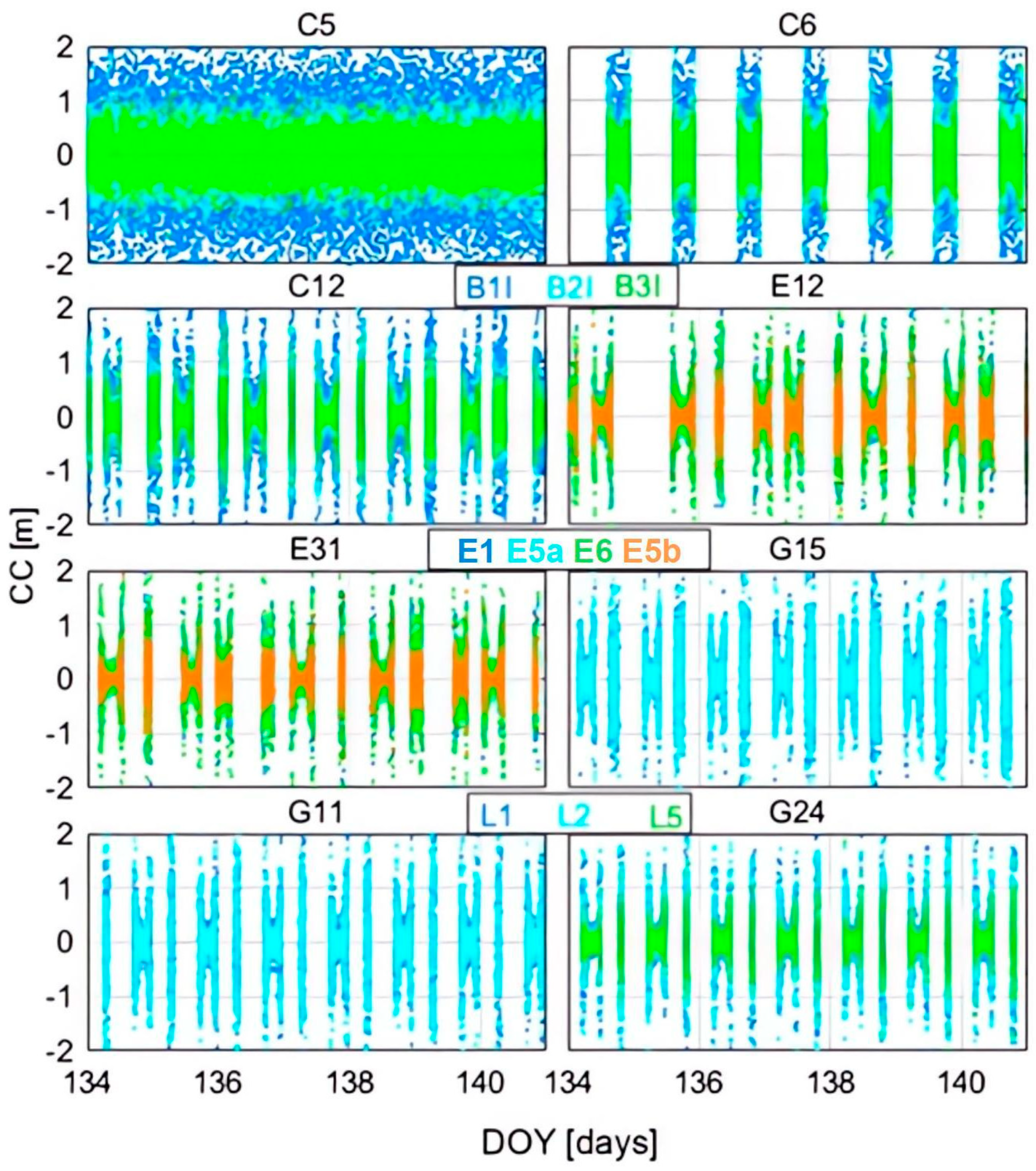
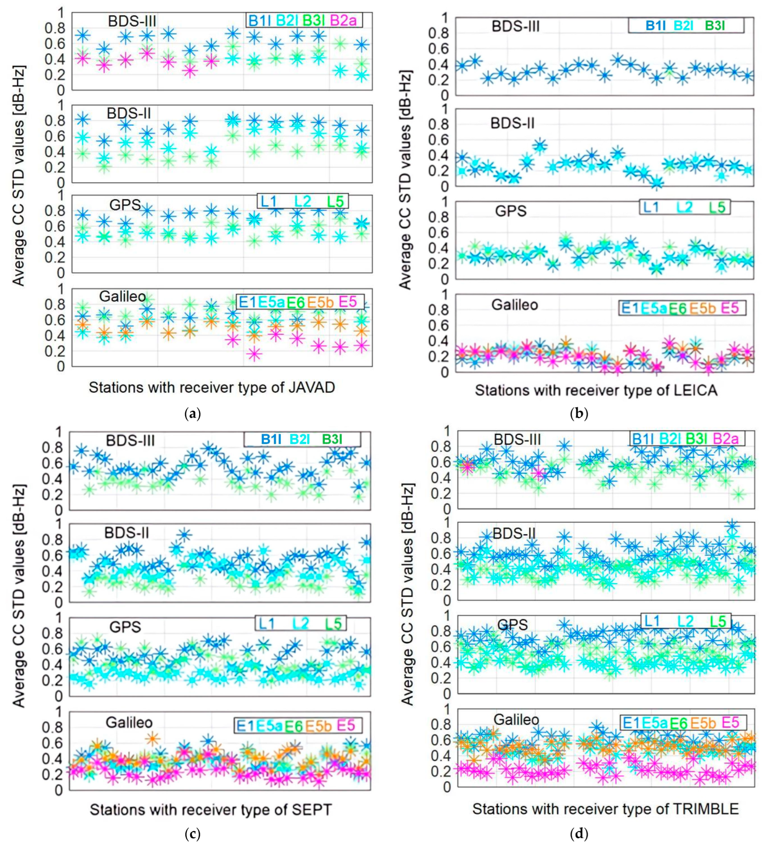
3.2. Experimental Analysis of Pseudorange Noise

Similarly, the experimental data given in Section 2.1 are used to perform the experimental analysis of pseudorange noise according to the Equation (8). CC is represented as the pseudorange noise.
The time series of CC values of BDS-3 C35 at B2a are given in Figure 4. The gray line indicates the satellite elevation. There is a certain correlation between the pseudorange noise and satellite elevation. The higher the satellite elevation, the smaller the noise, and vice versa. In Figure 5, the time series of CC values of four BDS-3 satellites at different signals are depicted. The performances of the four satellites are almost the same, and all of them show elevation-dependent and periodic characteristics. Corresponding to the high signal power, the B2a signal possesses the lowest noise level among the three signals B1I, B3I, and B2a.
Similarly, the time series of CC values for BDS-2, Galileo, and GPS satellites are given in Figure 6. For BDS-2, the GEO and IGSO satellites have larger noise levels than MEO satellites, which can also be related to their higher orbital altitude. Possessing high signal power, BDS-2 B3I, GPS L5, and Galileo E5b show smaller noise than other signals. It is worth noting that although GPS L2 has a low signal power, its noise level is not significantly greater than the other signals, which indicates that the noise level is not only related to the signal power.
Similar to the comparison of C/N0 on each station in Figure 3, STDs of CC values at different signals on each station are depicted in Figure 7, which are used to reflect the code noise level. Comparisons of different signals on different stations have almost identical characteristics, indicating that the pseudorange noise levels of different signals have little relationship with the receiver type. It is worth noting that the Galileo E5 signal exhibits optimal performance due to its high signal power.

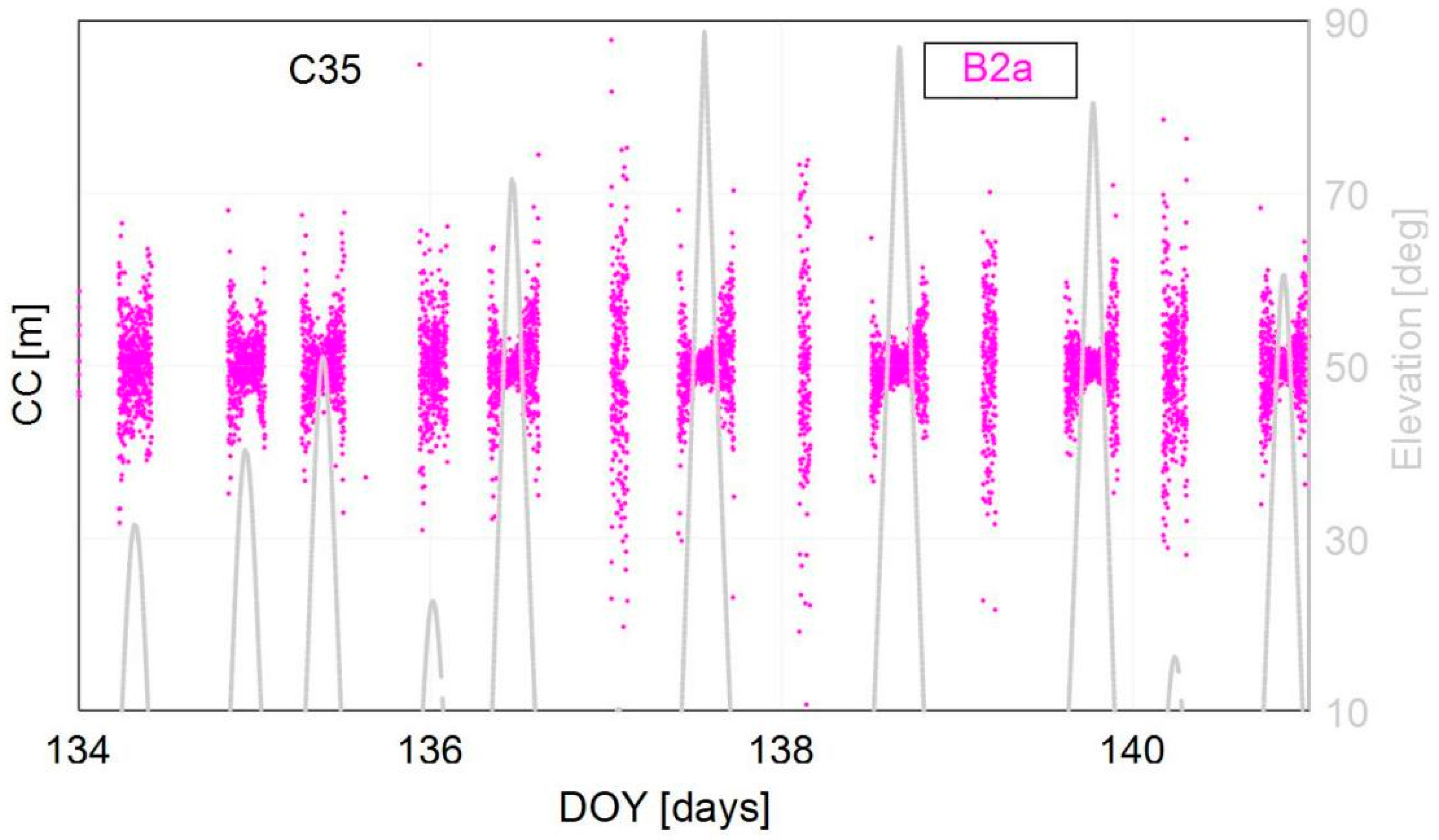
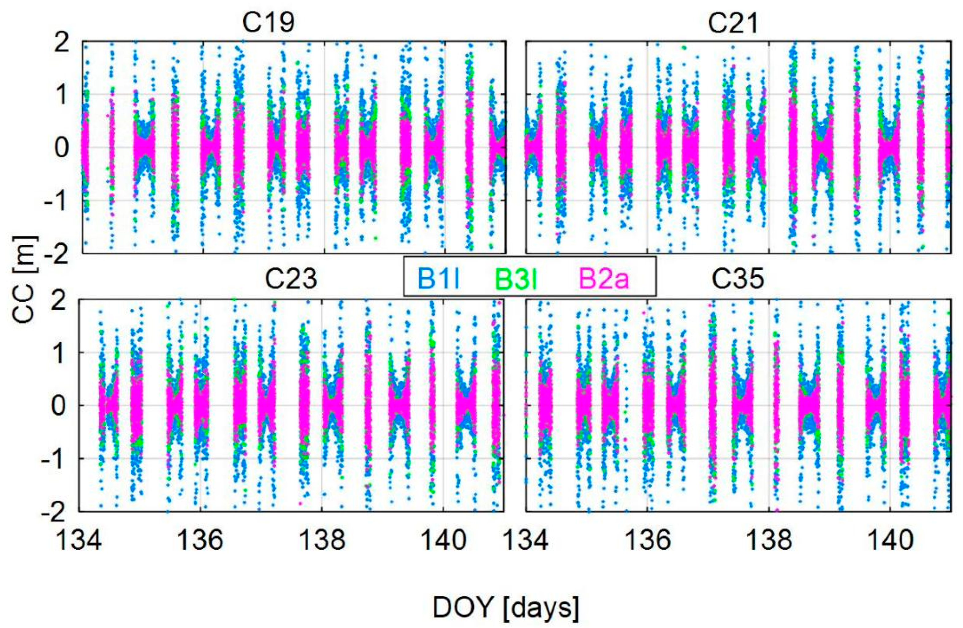
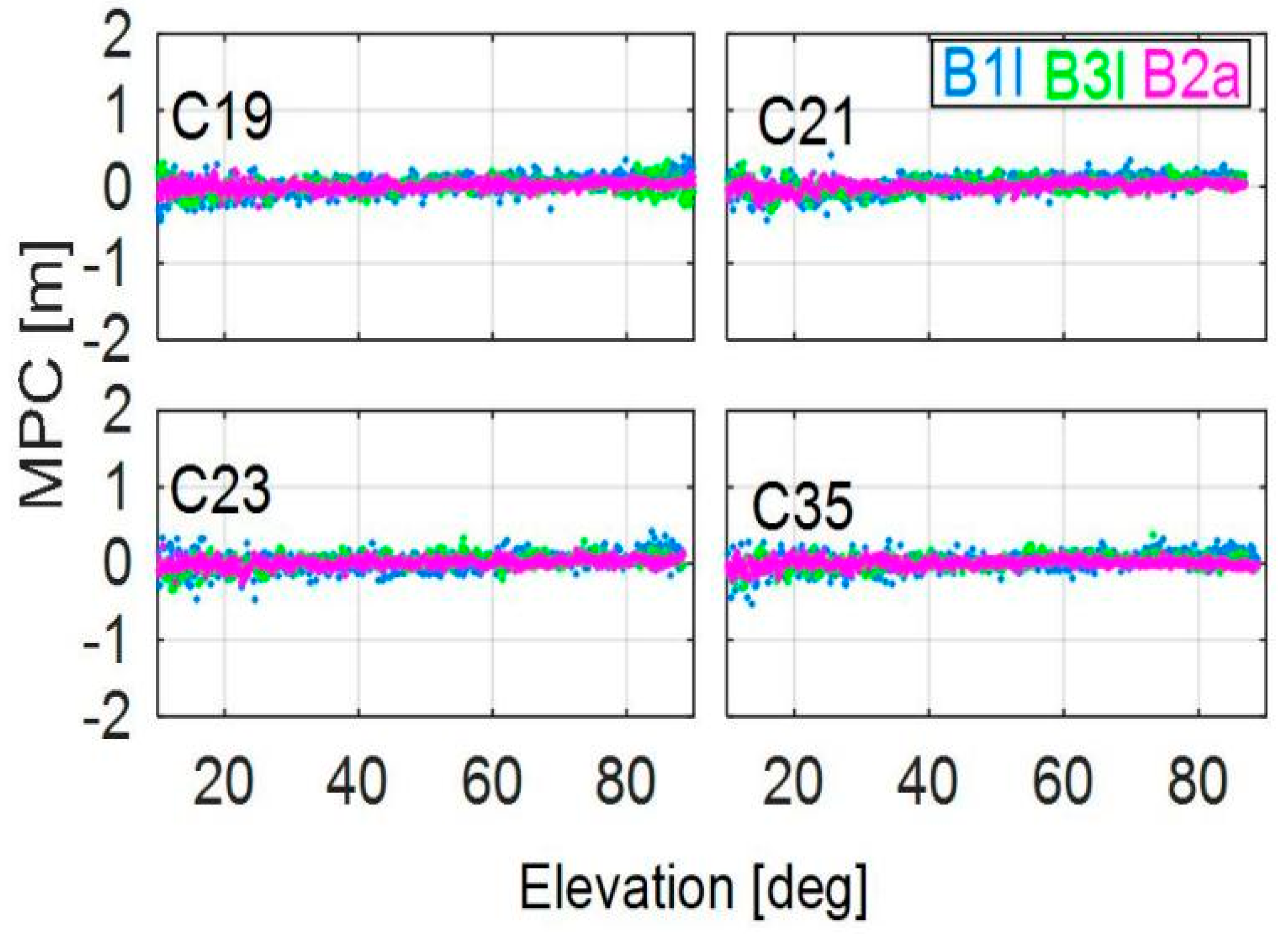
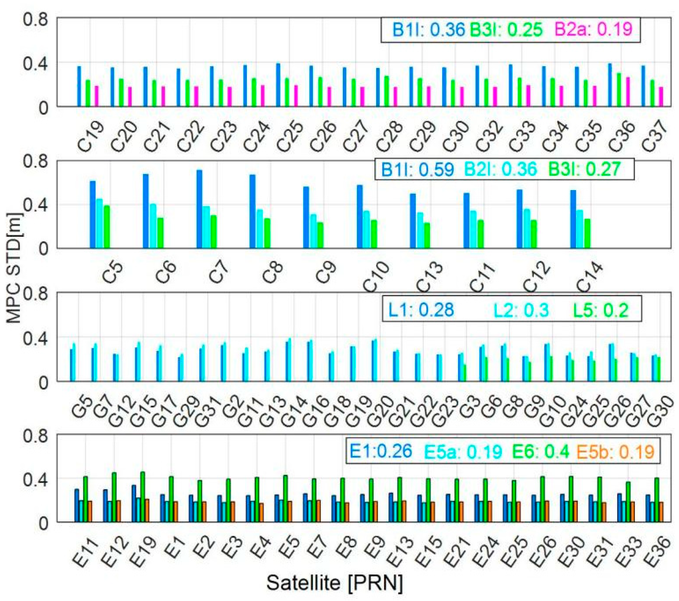
3.3. Experimental Analysis of Multipath

Corresponding to Figure 5 and Figure 6, comparisons of multipath values are presented in Figure 8 and Figure 9, respectively. The BDS-3 satellites perform better than BDS-2, and their multipath values no longer tend to vary with the elevation, which may be related to the better multipath resistance of their new modulated signals. In addition, the on-satellite multipath errors that appeared on BDS-2 satellites are no longer present on the BDS-3 satellites. The BDS-3 B2a, GPS L5, and Galileo E5b have significantly smaller multipath errors than other signals.
In order to more clearly compare the magnitude of multipath values at each signal, the STD values of multipath combinations for each satellite at different signals are shown in Figure 10. The accuracies of BDS-3 B2a, BDS-2 B3I, GPS L5, and Galileo E5b are superior to other signals in their respective systems.
Similar to the comparison of C/N0 and CC values for each station, the STD values of the multipath combinations for each type of receiver at different signals are shown in Figure 11. Similar characteristics can be found, namely that the multipath values have little relationship with the receiver type. Similarly, the Galileo E5 signal exhibits superior performance compared to all other signals, regardless of receiver type.

4. Discussion

By using data from different types of receivers and constructing models to evaluate signal power, code noise, and multipath effects, the satellite and signal performance of BDS and other systems such as GPS, Galileo were analyzed and compared.
The receiver type has little influence on C/N0 values. For BDS, signal powers of BDS-3 satellites are approximate 2–3 dB-Hz higher than those of BDS-2 satellites at the same frequency, which may be related to its advance modulation, and B2a of BDS-3, E5 of Galileo, and L5 of GPS have stronger signal powers.
The pseudorange noise levels of different signals have little relationship with the receiver type. It is worth noting that the Galileo E5 signal exhibits optimal performance due to its high signal power. The observation accuracy of E5 can reach 0.2 m, which is the highest among all the signals, regardless of receiver types, and next highest are BDS-3 B2a and GPS L5.
Similar characteristics can be found, namely that the multipath values have little relationship with the receiver type. Not being affected by the systematic code errors of BDS-2, the observations of BDS-3 satellites contain smaller multipath errors than that of BDS-2 satellites. As for the multipath suppression performance, the BDS-3 signal B2a, GPS L5, and Galileo E5b perform better than the other signals, which may be related to their wide signal bandwidths. The Galileo E5 signal exhibits superior performance compared to all other signals, regardless of receiver type.
In conclusion, the signals B2a, E5, and L5 exhibit advantages over the other signals, which may be attributed to the advanced signal modulation method.

5. Conclusions

A comprehensive evaluation of the signal characteristics of BDS, Galileo, and GPS was conducted using data from four types of receivers of MGEX stations. The following conclusion can be drawn.
In terms of signal power, the BDS-3 satellites have better manifestation than the BDS-2 satellites, and the signal B2a is better than B1I and B3I, while E5 of Galileo and L5 of GPS perform better than the other signals of the respective systems. The pseudorange noise exhibits characteristics of periodicity and variation with satellite elevation. The BDS-3 B2a signal possesses smaller noise than the other signals of BDS. The signal L5 performs better than the other signals of GPS, while the Galileo E5 signal performs best among all the signals of the three systems, regardless of receiver types. The MP error of BDS-3 is on the same level as that of GPS and Galileo, which is apparently smaller than that of BDS-2, and the systematic biases which exist in the pseudorange observations of BDS-2 are absent for BDS-3. Similar to the characteristics of the CC values, the BDS-3 B2a, GPS L5, and Galileo E5b have significantly smaller multipath errors than other signals. In general, the C/N0, CC, and multipath values have little relationship with the receiver type, but they affect each other.
In this paper, although some preliminary conclusions and research results have been achieved, there are still the following studies that need to be further deepened and expanded, due to system development and personal conditions, etc. The paper mainly focuses on the data quality between different types of satellites and different frequency observations of BDS/Galileo/GPS, but it does not conduct a detailed study of the observation stochastic model based on this. With the availability of BDS-3 and more Galileo FOC satellite observations, the establishment of a stochastic model that reflects the differences in the stochastic characteristics of different observations based on the data quality analysis to achieve high-precision-combined multi-GNSS navigation and positioning will become the key of the next research.

Author Contributions

Conceptualization, Y.T. and G.X.; methodology, Y.T. and R.G.; software, Y.T. and D.Z.; validation, L.Z. and J.G.; formal analysis, J.X.; investigation, Y.H.; resources, X.D.; writing—original draft preparation, Y.T.; writing—review and editing, D.H. and Z.Q.; visualization, J.X. and L.Z.; supervision, D.Z.; project administration, G.X.; funding acquisition, R.G. All authors have read and agreed to the published version of the manuscript.

Funding

This work was supported by the National Natural Science Foundation of China (grant nos. 42274045, 42004028 and 41904039), Natural Science Foundation of Henan (grant no. 232300421105) and China Postdoctoral Science Foundation (grant no. 2023M733285).

Data Availability Statement

The raw data supporting the conclusions of this article will be made available by the authors on request. The data can be found at the IGS official website (http://www.igs.org/mgex/data-products/#data, accessed on 2 April 2024).

Acknowledgments

The authors express great gratitude to IGS and iGMAS for providing the GNSS data.

Conflicts of Interest

The authors declare no conflict of interest.

References

  1. ILRS BeiDou (COMPASS) Center of Mass Information. Available online: https://ilrs.gsfc.nasa.gov/missions/satellite_missions/current_missions/bm13_general.html (accessed on 12 April 2024).
  2. Yang, Y.; Yang, Y.; Hu, X.; Tang, C.; Guo, R.; Zhou, Z.; Xu, J.; Pan, J.; Su, M. BeiDou-3 broadcast clock estimation by integration of observations of regional tracking stations and inter-satellite links. GPS Solut. 2021, 25, 57. [Google Scholar] [CrossRef]
  3. CSNO. Report on the Development of BeiDou Navigation Satellite System (Version 2.1). Available online: http://www.beidou.gov.cn/xt/gfxz/201805/P020180509588857259014.pdf (accessed on 10 December 2021).
  4. Gu, S.; Wang, Y.; Zhao, Q.; Zheng, F.; Gong, X. BDS-3 differential code bias estimation with undifferenced uncombined model based on triple-frequency observation. J. Geod. 2020, 94, 45. [Google Scholar] [CrossRef]
  5. CSNO. Development of BeiDou Navigation Satellite System (Version 4.0). Available online: http://www.beidou.gov.cn/xt/gfxz/201912/P020191227430565455478.pdf (accessed on 10 December 2021).
  6. Li, X.; Li, X.; Liu, G.; Yuan, Y.; Freeshah, M.; Zhang, K.; Zhou, F. BDS multi-frequency PPP ambiguity resolution with new B2a/B2b/B2a + b signals and legacy B1I/B3I signals. J. Geod. 2020, 94, 107. [Google Scholar] [CrossRef]
  7. Zhang, X.; Li, X.; Lu, C.; Wu, M.; Pan, L. A comprehensive analysis of satellite-induced code bias for BDS-3 satellites and signals. Adv. Space Res. 2019, 63, 2822–2835. [Google Scholar] [CrossRef]
  8. Zhang, Z.; Li, B.; Nie, L.; Wei, C.; Jia, S.; Jiang, S. Initial assessment of BeiDou-3 global navigation satellite system: Signal quality, RTK and PPP. GPS Solut. 2019, 23, 1–12. [Google Scholar] [CrossRef]
  9. Lu, M.; Li, W.; Yao, Z. Overview of BDS III new signals. Navigation 2019, 66, 19–35. [Google Scholar] [CrossRef]
  10. China Satellite Navigation System Administration Office. BDS Satellite Navigation System Space Signal Interface Control Document Open Service Signal B1C (Version 1.0) [EB/OL][R]. 27 December 2017. Available online: http://www.beidou.gov.cn/xt/gfxz/201712/P020171226741342013031.pdf (accessed on 18 May 2022).
  11. China Satellite Navigation System Administration Office (CSNO). BDS Satellite Navigation System Space Signal Interface Control Document Open Service Signal B2a (Version 1.0) [EB/OL][R]. 27 December 2017. Available online: http://www.beidou.gov.cn/xt/gfxz/201712/P020171226742357364174.pdf (accessed on 18 May 2022).
  12. China Satellite Navigation System Administration Office (CSNO). BDS Satellite Navigation System Space Signal Interface Control Document Open Service Signal B3I (Version 1.0) [EB/OL][R]. 9 February 2018. Available online: http://www.beidou.gov.cn/xt/gfxz/201802/P020180209623601401189.pdf (accessed on 18 May 2022).
  13. China Satellite Navigation System Administration Office (CSNO). BDS Satellite Navigation System Space Signal Interface Control Document Open Service Signal B1I (Version 1.0) [EB/OL][R]. 27 February 2019. Available online: http://www.beidou.gov.cn/xt/gfxz/201902/P020190227593621142475.pdf (accessed on 18 May 2022).
  14. Gaglione, S.; Angrisano, A.; Castaldo, G.; Freda, P.; Gioia, C.; Innac, A. The first Galileo FOC satellites: From useless to essential. In Proceedings of the 2015 IEEE International Geoscience and Remote Sensing Symposium, Milan, Italy, 26–31 July 2015; IEEE: Piscataway, NJ, USA, 2015. [Google Scholar]
  15. Montenbruck, O.; Hauschild, A.; Steigenberger, P.; Hugentobler, U.; Teunissen, P.; Nakamura, S. Initial assessment of the compass/BDS-2 regional navigation satellite system. GPS Solut. 2013, 17, 211–222. [Google Scholar] [CrossRef]
  16. Hauschild, A.; Montenbruck, O.; Sleewaegen, J.; Huisman, L.; Teunissen, P. Characterization of Compass M-1 Signals. GPS Solut. 2012, 16, 117–126. [Google Scholar] [CrossRef]
  17. Wang, G.; Jong, K.; Zhao, Q.; Hu, Z.; Guo, J. Multipath analysis of code measurements for BDS geostationary satellites. GPS Solut. 2015, 19, 129–139. [Google Scholar] [CrossRef]
  18. Wanninger, L.; Beer, S. BDS satellite-induced code pseudorange variations: Diagnosis and therapy. GPS Solut. 2015, 19, 639–648. [Google Scholar] [CrossRef]
  19. Zaminpardaz, S.; Teunissen, P. Analysis of Galileo IOV + FOC signals and E5 RTK performance. GPS Solut. 2017, 21, 1855–1870. [Google Scholar] [CrossRef]
  20. Pan, L.; Zhang, X.; Liu, J.; Li, X.; Li, X. Analysis and correction of the inter-frequency clock bias for BDS satellites. In China Satellite Navigation Conference (CSNC) 2016 Proceedings; Springer: Singapore, 2016; Volume II, pp. 115–128. [Google Scholar]
  21. Yang, Y.; Li, J.; Wang, A.; Xu, J.; He, H.; Guo, H.; Shen, J.; Dai, X. Preliminary assessment of the navigation and positioning performance of BDS regional navigation satellite system. Sci. China Earth Sci. 2014, 57, 144–152. [Google Scholar] [CrossRef]
  22. Tian, Y.; Sui, L.; Xiao, G.; Zhao, D.; Tian, Y. Analysis of BDS/Galileo/GPS signals and RTK performance. GPS Solut. 2019, 23, 37. [Google Scholar] [CrossRef]
  23. Simsky, A.; Sleewaegen, J.; Crisci, M. Performance assessment of Galileo ranging signals transmitted by GSTB-v2 satellites. In Proceedings of the 19th International Technical Meeting of the Satellite Division of the Institute of Navigation (ION GNSS 2006), Fort Worth, TX, USA, 26–29 September 2006; pp. 1547–1559. [Google Scholar]
  24. Zhang, X.; Wu, M.; Liu, W.; Li, X.; Yu, S.; Lu, C. Initial assessment of the COMPASS/BDS-3: New-generation navigation signals. J. Geod. 2017, 91, 1225–1240. [Google Scholar] [CrossRef]
  25. Fu, Z.; Gong, X.; Gu, S.; Lou, Y.; Shi, S. Accounting for biases between BDS-3 and BDS-2 overlapping B1I/B3I signals in BeiDou global ionospheric modeling and DCB determination. Adv. Space Res. 2022, 69, 3677–3691. [Google Scholar]
  26. Mi, X.; Sheng, C.; ElMowafy, A.; Zhang, B. Characteristics of receiver-related biases between BDS-3 and BDS-2 for five frequencies including inter-system biases, differential code biases, and differential phase biases. GPS Solut. 2021, 25, 3. [Google Scholar] [CrossRef]
  27. Liang, Y.; Xu, J.; Wu, M.; Li, F. Analysis of the Long-Term Characteristics of BDS On-Orbit Satellite Atomic Clock: Since BDS-3 Was Officially Commissioned. Remote Sens. 2022, 14, 4535. [Google Scholar] [CrossRef]
  28. Wang, E.; Song, W.; Zhang, Y.; Shi, X.; Wang, Z.; Xu, S.; Shu, W. Evaluation of BDS/GPS Multi-Frequency RTK Positioning Performance under Different Baseline Lengths. Remote Sens. 2022, 14, 3561. [Google Scholar] [CrossRef]
  29. Yang, Y.; Mao, Y.; Sun, B. Basic performance and future developments of BeiDou global navigation satellite system. Satell. Navig. 2020, 1, 1. [Google Scholar] [CrossRef]
  30. Shi, J.; Ouyang, C.; Huang, Y.; Peng, W. Assessment of BDS-3 global positioning service: Ephemeris, SPP, PPP, RTK, and new signal. GPS Solut. 2020, 24, 81. [Google Scholar] [CrossRef]
  31. Gu, S.; Dai, C.; Fang, W.; Zheng, F.; Wang, Y.; Zhang, Q.; Lou, Y.; Niu, X. Multi-GNSS PPP/INS tightly coupled integration with atmospheric augmentation and its application in urban vehicle navigation. J. Geod. 2021, 95, 64. [Google Scholar] [CrossRef]
  32. Ma, Z.; Cui, J.; Liu, Z.; Su, X.; Xiang, Y.; Xu, Y.; Deng, C.; Hui, M.; Li, Q. Influence of Inter-System Biases on Combined Single-Frequency BDS-2 and BDS-3 Pseudorange Positioning of Different Types of Receivers. Remote Sens. 2024, 16, 1710. [Google Scholar] [CrossRef]
  33. Dang, X.; Yin, X.; Zhang, Y.; Gao, C.; Wu, J.; Liu, Y. Improved Medium Baseline RTK Positioning Performance Based on BDS/Galileo/GPS Triple-Frequency only Observations. Remote Sens. 2023, 15, 5198. [Google Scholar] [CrossRef]
  34. Xiao, K.; Sun, F.; Zhu, X.; Zhou, P.; Ma, Y.; Wang, Y. Assessment of overlapping triple-frequency BDS-3/BDS-2/INS tightly coupled integration model in kinematic surveying. GPS Solut. 2024, 28, 2. [Google Scholar] [CrossRef]
  35. Shu, B.; Tian, Y.; Qu, X.; Li, W.; Huang, G.; Du, Y.; Zhang, Q. Estimation of BDS-2/3 phase observable-specific signal bias aided by double-differenced model: An exploration of fast BDS-2/3 real-time PPP. GPS Solut. 2024, 28, 88. [Google Scholar] [CrossRef]
Figure 1. Average C/N0 values against the elevations of all the satellites for BDS B1I/B2I/B3I/B2a based on observations collected from MGEX stations during DOY 134–140 in 2019. Only the results of the representative receiver type JAVAD are plotted. (II: BDS-2; IIIs: BDS-3 experimental system; III: BDS-3).
Remotesensing 16 02277 g001
Figure 2. Average C/N0s against the elevations of different signals. The left panel is only for the BDS signals, while the right panel is for all the signals of BDS-3, Galileo, and GPS.
Remotesensing 16 02277 g002
Figure 3. Comparison of C/N0 values at different signals for different receiver types. The horizontal axis in subfigure (a) represents 15 stations with the receiver type JAVAD, while that in subfigure (b) represents 24 stations with the receiver type LEICA, that in subfigure (c) represents 29 stations with the receiver type SEPT, and that in subfigure (d) represents 40 stations with the receiver type TRIMBLE.
Remotesensing 16 02277 g003
Figure 4. Time series of CC values of the BDS-3 C35 satellite at the B2a signal during DOY 134–140 in 2019. The satellite elevation over time is indicated by the gray line.
Remotesensing 16 02277 g004
Figure 5. Time series of CC values of the four selected BDS-3 satellites at B1I/B3I/B2a during DOY 134–140 in 2019.
Remotesensing 16 02277 g005
Figure 6. Time series of CC values for BDS-2 (C5, C6, and C12), Galileo (E12 and E31), and GPS (G15, G11, and G24) satellites at different signals during DOY 134–140 in 2019. Legends B1I (light green), B2I (bright green), and B3I (light blue) are for BDS satellites C5, C6, and C12. Legends E1 (light blue), E5a (light green), E6 (bright green), and E5b (light yellow) are for Galileo satellites E12 and E31. Legends L1 (light blue), L2 (light green), L5 (bright green) are for GPS satellites G15, G11 and G24.
Remotesensing 16 02277 g006
Figure 7. Comparison of average CC STD values in different stations. The horizontal axis in subfigure (a) represents 15 stations with receiver type JAVAD, while that in subfigure (b) represents 24 stations with receiver type LEICA, that in subfigure (c) represents 29 stations with receiver type SEPT, and that in subfigure (d) represents 40 stations with receiver type TRIMBLE. In each subgraph, the 4 panels are for BDS-3 B1I/B3I/B2a, BDS-2 B1I/B2I/B3I, GPS L1/L2/L5, and Galileo E1/E5a/E6/E5b/E5, respectively.
Remotesensing 16 02277 g007
Figure 8. Multipath values against satellite elevation for BDS-3 C19, C21, C23, and C35 satellites during DOY 134–140 in 2019. MPC stands for Multipath Combination.
Remotesensing 16 02277 g008
Figure 9. Multipath values against satellite elevation for BDS-2 (C5, C21, and C23), Galileo (E12 and E31), and GPS (G15, G11, and G24) satellites during DOY 134–140 in 2019. Legends B1I (light blue), B2I (light green) and B3I (bright green) are for BDS satellites C5, C6, and C12. Legends E1 (light blue), E5a (light green), E6 (bright green), and E5b (light yellow) are for Galileo satellites E12 and E31. Legends L1 (light blue), L2 (light green) and L5 (bright green) are for GPS satellites G15, G11 and G24.
Remotesensing 16 02277 g009
Figure 10. STDs of multipath combinations for different satellites. The four panels from top to bottom are for BDS-3, BDS-2, GPS, and Galileo satellites, respectively.
Remotesensing 16 02277 g010
Figure 11. Comparison of average MPC STD values in different stations. The horizontal axis in subfigure (a) represents 15 stations with receiver type JAVAD, while that in subfigure (b) represents 24 stations with receiver type LEICA, that in subfigure (c) represents 29 stations with receiver type SEPT, and that in subfigure (d) represents 40 stations with receiver type TRIMBLE. In each subgraph, the 4 panels are for BDS-3 B1I/B3I/B2a, BDS-2 B1I/B2I/B3I, GPS L1/L2/L5, and Galileo E1/E5a/E6/E5b/E5, respectively.
Remotesensing 16 02277 g011
Table 1. BDS-3 open service signal system.
Signal ComponentFrequency (MHz)Bandwidth (MHz)Code Rate (Mcps)ModulationBroadcast SatelliteCompatible Frequency
B1I1561.094.0922.046BPSK (2)All
B3I1268.5220.4610.23BPSK (10)All
B1C_data1575.4232.7361.023BOC (1,1)IGSO MEOL1, E1
B1C_pilotQMBOC (6,1,4/33)
B2a_data1176.4520.4610.23BPSK (10)IGSO MEOL5, E5a
B2a_pilot
B2b_I1207.1410.23QPSK (10)IGSO MEOE5b
B2b_Q
Table 2. Classifications of different receiver types in MGEX stations (G: GPS; E: Galileo; C: BDS).
Receiver TypeFirmware VersionObservation SignalSelection of Stations
JAVADTRE_3 3.7.6G: L1, L2, L5
E: E1, E5a, E5b, E5
C: B1I, B2I, B3I, B2a
POTS, SGOC, SUTM, ULAB, URUM, WIND, WUH2
OthersG: L1, L2, L5
E: E1, E5a, E5b, E5
C: B1I, B2I, B3I
9 measuring stations, such as BSHM, KOKV
LEICAGR10, GR25, GR30, GR50G: L1, L2, L5
E: E1, E5a, E5b, E5
C: B1I, B2I
25 measuring stations, such as ALIC, EBRE
TRIMBLENETR9G: L1, L2, L5
E: E1, E5a, E5b, E5
C: B1I, B2I, B3I,
48 measuring stations, such as BOR1, CUT0
SEPTPOLARX5G: L1, L2, L5
E: E1, E5a, E5b, E5, E6
C: B1I, B2I, B3I
40 measuring stations, such as CEBR, HOB2
Table 3. Selection of signals in different multipath combinations.
SystemGalileoBDS-2BDS-3GPS
f j E1E5aE5bE5E6B1IB2IB3IB1IB3IB2aL1L2L5
f i E5aE1E1E1E1B2IB1IB1IB3IB1IB1IL2L1L1
Disclaimer/Publisher’s Note: The statements, opinions and data contained in all publications are solely those of the individual author(s) and contributor(s) and not of MDPI and/or the editor(s). MDPI and/or the editor(s) disclaim responsibility for any injury to people or property resulting from any ideas, methods, instructions or products referred to in the content.

